EP1489896B1 - Faucheuse agricole comportant un vehicule porteur et plusieurs unites de travail - Google Patents
Faucheuse agricole comportant un vehicule porteur et plusieurs unites de travail Download PDFInfo
- Publication number
- EP1489896B1 EP1489896B1 EP03725285A EP03725285A EP1489896B1 EP 1489896 B1 EP1489896 B1 EP 1489896B1 EP 03725285 A EP03725285 A EP 03725285A EP 03725285 A EP03725285 A EP 03725285A EP 1489896 B1 EP1489896 B1 EP 1489896B1
- Authority
- EP
- European Patent Office
- Prior art keywords
- agricultural machine
- work
- work units
- units
- carrying vehicle
- Prior art date
- Legal status (The legal status is an assumption and is not a legal conclusion. Google has not performed a legal analysis and makes no representation as to the accuracy of the status listed.)
- Revoked
Links
- 230000008878 coupling Effects 0.000 description 15
- 238000010168 coupling process Methods 0.000 description 15
- 238000005859 coupling reaction Methods 0.000 description 15
- 239000000725 suspension Substances 0.000 description 5
- 230000005540 biological transmission Effects 0.000 description 4
- 244000025254 Cannabis sativa Species 0.000 description 2
- 230000000694 effects Effects 0.000 description 2
- 210000000056 organ Anatomy 0.000 description 2
- 230000001105 regulatory effect Effects 0.000 description 2
- 230000000284 resting effect Effects 0.000 description 2
- 238000012550 audit Methods 0.000 description 1
- 238000006073 displacement reaction Methods 0.000 description 1
- 238000001035 drying Methods 0.000 description 1
- 230000004048 modification Effects 0.000 description 1
- 238000012986 modification Methods 0.000 description 1
- 230000007704 transition Effects 0.000 description 1
Images



Classifications
-
- A—HUMAN NECESSITIES
- A01—AGRICULTURE; FORESTRY; ANIMAL HUSBANDRY; HUNTING; TRAPPING; FISHING
- A01D—HARVESTING; MOWING
- A01D57/00—Delivering mechanisms for harvesters or mowers
- A01D57/20—Delivering mechanisms for harvesters or mowers with conveyor belts
-
- A—HUMAN NECESSITIES
- A01—AGRICULTURE; FORESTRY; ANIMAL HUSBANDRY; HUNTING; TRAPPING; FISHING
- A01D—HARVESTING; MOWING
- A01D75/00—Accessories for harvesters or mowers
- A01D75/30—Arrangements for trailing two or more mowers
Definitions
- the present invention relates to an agricultural machine comprising a vehicle carrier and several work units intended to cut a standing product, said work units being connected to said carrier vehicle.
- a self-propelled mower with a carrier vehicle and three work units.
- Said carrier vehicle is intended for support and drive said work units.
- said vehicle carrier includes a chassis, a motor, and a cockpit.
- Said work units are intended for cutting a standing product such as grass for example.
- This familiar self-propelled mower has more precisely one frontal work unit and two lateral work units. View in a forward direction, the front work unit is disposed forward of said carrier vehicle.
- the side work units are arranged behind the unit of frontal work, on both sides of the area worked by the latter. So, this known self-propelled mower has a working width of up to 9 meters. In the transport position, the front work unit is moved away from the ground by a movement of translation substantially vertical.
- US Patent 3,563,011 relates to a machine with five units of chopped off. Two of these cutting units are located on the right side of the tractor, two others are on the left side and one is under the tractor. This arrangement with a cutting unit under the tractor is not suitable for a agricultural machinery especially because of the lack of space for the passage of the mass of products at work and for clearing the ground cutter unit for transportation.
- the object of the present invention is to obtain an agricultural machine allowing an increased working width while respecting, in the transport position, the legislation regulating traffic on public roads.
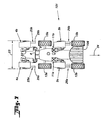
- FIG. 1 represents, in plan view, an agricultural machine (1) moving following a direction and a direction of advance indicated by the arrow (2).
- the following notions "before” and “backwards”, “before” and “behind” are defined in relation to the direction in advance (2) and the notions “right” and “left” are defined by looking at said agricultural machine (1) from the rear in the direction of advance (2).
- Said agricultural machine (1) comprises a carrier vehicle (3) and work (4, 5).
- Said work units (4, 5) are intended to cut a product on foot such as grass for example.
- said carrier vehicle (3) is intended to drive and support at least partially the said work units (4, 5).
- said carrier vehicle (3) has a frame resting on the ground by means of four wheels (15a, 15b). Said four wheels (15a, 15b) are advantageously directed to provide said agricultural machine (1) of remarkable maneuverability. It is also planned a engine and a transmission allowing said carrier vehicle (3) to be autonomous. In a preferred manner, said transmission renders said four wheels (15a, 15b). Also preferentially, said motor is in addition able to animate said work units (4, 5). Power transmission said engine to said work units (4, 5) is done by means of elements of mechanical and / or hydraulic transmission known to those skilled in the art. said carrier vehicle (3) comprises a cockpit (6) allows a driver to directing the assembly of said agricultural machine (1).
- Each work unit (4, 5) has a cutting device resting at least partially on the ground during work.
- said cutting device consists of a multitude cutting members rotated about a respective axis directed towards the high.
- the path described by said rotating cutting members has been represented by dashed circles (16).
- Such a cutting device is known of the man of the art, it will not be described further.
- said agricultural machine (1) has two front work units (4a, 4b) and two units side workpieces (5a, 5b).
- said front work units (4a, 4b) are arranged transversely to said direction of advance (2) and preferably in the extension of one another.
- said front work units (4a, 4b) are arranged in such a way that their respective working areas (17a, 17b) overlap somewhat.
- said standing product will be perfectly cut over the entire work area (18) covered by the said work units frontal (4a, 4b).
- said front working units (4a, 4b) are preferably arranged symmetrically with respect to a vertical plane median of said carrier vehicle (3).
- the width of said working zone (18) is greater than the width (19) on the ground of said carrier vehicle (3). So when working said vehicle carrier (3) does not crush the standing product.
- said lateral working units (5a, 5b) are also arranged transversely to said direction of advance (2) and advantageously in the extension one of the other.
- said lateral work units (5a, 5b) are additionally arranged so that their respective working areas (20a, 20b) overlap somewhat said work area (18).
- said lateral work units (5a, 5b) are preferably arranged behind said front working units (4a, 4b).
- said lateral working units (5a, 5b) are arranged behind said carrier vehicle (3). This gives a good distribution of the masses of said machine agricultural (1) on the different wheels (15a, 15b) of said carrier vehicle (3).
- said work units (4a, 4b, 5a, 5b) thus arranged allow said agricultural machine (1) to have a relatively large total work area (21).
- said agricultural machine (1) has a total working width around 11.5 meters.
- said work (4a, 4b, 5a, 5b) are moved so that said agricultural machine (1) complies with the legislation regulating traffic on public roads.
- this legislation limits in particular the width (23) of the agricultural machine (1) at 3 meters and the height (24) of said agricultural machine (1) at 4 meters.
- each front work unit (4a, 4b) is pivotally linked to said carrier vehicle (3) by means of a respective articulated joint (7a, 7b) following said direction of advance (2). It is also planned to maneuvering, for example cylinders, for pivoting said work units front ends (4a, 4b) about said respective hinge (7a, 7b) of a position substantially horizontal working at a substantially vertical position of transport, and vice versa. In transport position, said work units front ends (4a, 4b) are preferably arranged symmetrically with respect to said vertical median plane of said carrier vehicle (3).
- said respective hinges (7a, 7b) are positioned so that, in transport position, said front work units (4a, 4b) do not exceed the authorized width (23) for driving on public roads. It can be noted that said carrier vehicle (3) also respects said authorized width (23).
- Said front work units (4a, 4b) are linked by means of said respective hinges (7a, 7b) to a hitch structure (8), which coupling structure (8) is in turn connected to a coupling device frontal (9) of said carrier vehicle (3).
- Said front coupling device (9) represented by way of non-limiting example in the form of a coupling device "3 points”, advantageously allows to move in one direction substantially vertical said hitching structure (8) and therefore said front work units (4a, 4b). So when moving from the horizontal position at a substantially vertical transport position, said device coupling (9) allows, if necessary, to facilitate the maneuvering away from the ground said front work units (4a, 4b). Once said position substantially vertical transport reached, said coupling device (9) allows, if necessary, to slightly reduce the height (24) of said agricultural machine (1) by lowering said hitching structure (8).
- each lateral work unit (5a, 5b) is pivotally connected to said carrier vehicle (3) by means of a respective articulation (10a, 10b) of axis directed in said direction of advance (2). It is also planned to actuating means for pivoting said lateral working units (5a, 5b) of a horizontal working position at a substantially vertical transport position, and vice versa. In the transport position, said lateral working units (5a, 5b) are preferably arranged symmetrically with respect to said vertical plane median of said carrier vehicle (3).
- the said respective hinges (10a, 10b) are positioned so that, in transport position, said lateral working units (5a, 5b) do not exceed the authorized width (23) for driving on public roads.
- each lateral working unit (5a, 5b) is additionally connected in a manner sliding to said carrier vehicle (3) by means of a respective hinge (11a, 11b) of axis directed transversely to said direction of advance (2). he is also provided maneuvering devices for translating said work units lateral (5a, 5b) following said respective joints (11a, 11b). Each unit lateral work (5a, 5b) can thus be approached or removed from said vehicle carrier (3).
- the transverse displacement of said work units laterally (5a, 5b) advantageously makes it possible to modify the overlap between said work area (18) of said front work units (4a, 4b) and the areas respective workpieces (20a, 20b) of said lateral working units (5a, 5b).
- a such modification of the overlap may be advantageous when said machine agricultural (1) works in an incline or when working along a curve.
- the translation of each lateral work unit (5a, 5b) following said respective hinge (11a, 11b) can be ordered individually during work.
- the translating said lateral working units (5a, 5b) towards said carrier vehicle (3) in particular facilitates the pivoting of the latter around said joints (10a, 10b).
- said translation along said respective hinges (11a, 11b) also allows to reduce the height (24) of said agricultural machine (1).
- each lateral working unit (5a, 5b) is thus slidably connected to a respective bearing arm (12a, 12b) by means of said respective hinge (11a, 11b).
- each support arm (12a, 12b) is pivotally connected to said carrier vehicle (3) by means of said respective hinge (10a, 10b).
- said support arms (12a, 12b) are connected to the means of said respective hinges (10a, 10b) to a hitching structure (13), which coupling structure (13) is connected to a coupling device rear (14) of said carrier vehicle (3).
- Said rear coupling device (14) represented by way of non-limiting example in the form of a coupling device "3 points”, advantageously allows to move in one direction substantially vertical said hitch structure (13) and therefore said lateral work units (5a, 5b). So when moving from the horizontal position at a substantially vertical transport position, said device rear hitch (14) allows, if necessary, to facilitate the maneuvering away from the ground said lateral working units (5a, 5b).
- Said work units (4a, 4b, 5a, 5b) advantageously comprise a respective suspension device (22).
- each device suspension (22) makes it possible, on the one hand, to carry back at least part of the weight of the corresponding cutting device on said carrier vehicle (3).
- each suspension device (22) allows said cutting device a certain freedom of movement with respect to said carrier vehicle (3).
- Each device cutting can thus evolve individually in a direction substantially vertical and about a median axis of said work unit (4a, 4b, 5a, 5b) directed following said direction of advance (2). This freedom of movement allows advantageously said cutting device to follow the irregularities of the ground independently of said carrier vehicle (3).
- each suspension device (22) allows in addition to advantageously moving away from the ground each cutting device individually for example to perform maneuvers at the end of the field or to avoid an obstacle.
- Such suspension devices (22) are known to those skilled in the art, they will not be described further.
- said cockpit (6) comprises a control device related in particular to the actuators of said joints (7a, 7b, 10a, 10b, 11a, 11b).
- Said control device is intended autonomously managing the movement of said work units (4a, 4b, 5a, 5b) during the transition from the working position to the transport position, and Conversely.
- the driver of said agricultural machine (1) thus advantageously sees its simplified task.
- each work unit (4, 5) comprises also a treatment device for accelerating the drying of the product cut by the corresponding cutting device.
- each treatment device is constituted for example by a rotor or two counter-rotating rollers.
- each work unit (4a, 4b, 5a, 5b) additionally comprises a respective conveying device (25a, 25b, 26a, 26b) intended to move the cut product by the corresponding cutting device before that said cut product does not touch the ground.
- the product cut on said total work area (21) is grouped in two windrows (27a, 27b).
- the driver of said machine agricultural product (1) can pass from said first work configuration to said second working configuration, and conversely, from his cockpit (6).
- each conveying device (25a, 25b) respectively equipping said front work units (4a, 4b) each comprise a conveyor belt (29a, 29b) disposed transversely behind said cutting devices corresponding.
- Each conveying device (25a, 25b) is advantageously linked slidably to said corresponding front work unit (4a, 4b). In the working position, said conveying devices (25a, 25b) can thus be be translated horizontally and transversely to said feed direction (2).
- Operating devices are provided for this purpose.
- each conveyor belt (29a, 29b) comprises a carpet wrapped around two cylinders. At least one of said cylinders is driven by rotation by means of a motor. The direction of scrolling of these bands
- the conveyors (29a, 29b) can advantageously be reversed.
- the said meaning of of said conveyor belts (29a, 29b) has been represented with the aid of arrows in Figures 4 and 5.
- Said conveying devices (26a, 26b) respectively equipping said side working units (5a, 5b) each comprise two conveyor belts (30a, 31a; 30b, 31b) disposed one above the other.
- Said bands conveyors (30a, 31a, 30b, 31b) are arranged transversely behind the corresponding cutting device.
- each conveyor belt (30a, 31a, 30b, 31b) has a belt wrapped around it of two respective cylinders. At least one of said cylinders of each band conveyor (30a, 31a, 30b, 31b) is rotated by means of a motor.
- the lower conveyor belts (31a, 31b) are advantageously slidably connected to said unit of corresponding lateral work (5a, 5b). In working position, said bands lower conveyors (31a, 31b) can thus be translated horizontally and transversely to said feed direction (2). Maneuvering devices are provided for this purpose. Said upper conveyor belts (30a, 30b) and their respective cylinders retain a fixed position relative to said unit corresponding lateral work (5a, 5b). Said direction of scrolling said conveyor belts (30a, 31a, 30b, 31b) has been shown with arrows on Figures 4 and 5.
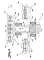
- said conveying devices front ends (25a, 25b) are brought closer to the median vertical plane of said carrier vehicle (3).
- the direction of travel of said conveyor belts (29a, 29b) is such that shown in FIG. 4.
- Said front conveying devices (25a, 25b) are dimensioned and translated so that the product cut by each front working unit (4a, 4b) is deposited next to said carrier vehicle (3) without however, to leave said respective working area (17a, 17b).
- said bands lower conveyors (31a, 31b) of said lateral conveying devices (26a, 26b) remain positioned under said upper conveyor belts respective ones (30a, 30b).
- said lower conveyor belts (31a, 31b) are not in contact with cut product.
- said lower conveyor belts (31a, 31b) are not driven in this work configuration.
- the direction of scrolling of these bands upper conveyors (30a, 30b) is as shown in FIG. 4.
- Said upper conveyor belts (30a, 30b) are dimensioned from so that the product cut by said lateral work unit corresponding (5a, 5b) is deposited immediately next to said half-swath existing (32a, 32b).
- front conveying devices (25a, 25b) are remote from the median vertical plane said carrier vehicle (3).
- the direction of travel of said conveyor belts (29a, 29b) is as shown in FIG. 5.
- the product cut by each unit front workpiece (4a, 4b) is thus deposited in front of said carrier vehicle (3) for form a single half-swath (33).
- said devices front conveying means (25a, 25b) are translated in such a way that front wheels (15a) and both rear wheels (15b) of said carrier vehicle (3) can pass on both sides of said half-swath (33).
- said lower conveyor belts (31a, 31b) of said lateral conveyances (26a, 26b) are translated towards the median vertical plane of said carrier vehicle (3).
- the direction of travel of said conveyor belts (30a, 30b) and lower conveyor belts (31a, 31b) are as shown in Figure 5.
- the product cut by said work unit side (5a, 5b) is thus first displaced by said upper conveyor belt (30a, 30b) then by said lower conveyor belt (31a, 31b).
- said lower conveyor belts (31a, 31b) are dimensioned so that that the product cut by the corresponding lateral working unit (5a, 5b) is deposited immediately next to said half-swath (33).
- Said swath (28) is advantageously arranged along a median longitudinal axis of said agricultural machine (1).
- FIGS 6 to 8 show a second embodiment of a agricultural machine (101) according to the present invention.
- This agricultural machine (101) has a number of elements that have been described previously. These elements will therefore keep the same reference number and will not be described again. It also includes a number of elements which are comparable to elements of the agricultural machine (1) described above. These elements will be assigned the same reference number as these elements comparable to the agricultural machine (1) but increased by 100. They will not be described only if necessary.
- said agricultural machine (101) also comprises two work units front ends (4a, 4b) and two lateral work units (5a, 5b) connected to a vehicle carrier (103). Views according to the direction in advance at work (2), said units of front work (4a, 4b) are arranged in front of said carrier vehicle (103). Said lateral working units (5a, 5b) are disposed behind said units front work (4a, 4b). In working position as shown on the FIGS. 6 and 8, said lateral working units (5a, 5b) are additionally provided with either side of the working area (18) of said front work units (4a, 4b).
- said lateral working units (5a, 5b) are arranged on the sides of said carrier vehicle (103).
- said carrier vehicle (103) includes a cockpit (106) disposed advantageously behind said lateral working units (5a, 5b).
- said work units (4a, 4b, 5a, 5b) are also displaced relative to said carrier vehicle (103) of to reach a transport position as shown in FIG. 7.
- each front work unit (4a, 4b) is pivotally linked said carrier vehicle (103). This connection has been widely described in the first embodiment shown in Figures 1 to 5.
- each lateral work unit (5a, 5b) is pivotally connected to said carrier vehicle (103) by means of a respective articulation (110a, 110b) of axis directed in said direction of advance (2). It is also planned to actuating means for pivoting said lateral working units (5a, 5b) of a horizontal working position at a substantially vertical transport position, and vice versa. In the transport position, said lateral working units (5a, 5b) are preferably also arranged symmetrically with respect to said plane vertical median of said carrier vehicle (103). In the light of FIG.
- the said respective hinges (110a, 110b) are positioned so that, in transport position, said lateral working units (5a, 5b) do not exceed said template (23) authorized to travel on public roads.
- said lateral working units (5a, 5b) are advantageously arranged between the front wheels (15a) and the rear wheels (15b) of said vehicle carrier (103).
- each lateral work unit (5a, 5b) is further slidably connected to said carrier vehicle (103) at means of a respective articulation (11a, 11b) of axis directed transversely to said advance direction (2). There are also maneuvering organs for translating said lateral work units (5a, 5b) according to said respective hinges (11a, 11b). Each lateral work unit (5a, 5b) can thus be closer or further away from said carrier vehicle (103).
- each lateral work unit (5a, 5b) is connected by means of said respective hinge (11a, 11b) to a respective carrier arm (12a, 12b).
- each support arm (12a, 12b) is connected by means of said articulation respective (110a, 110b) to said carrier vehicle (103).
- said agricultural machine (101) moves during transport following a advancing direction (34) in the opposite direction to said advancing direction (102).
- said cockpit (106) is advantageously of the "driving" type. reversed “.
- said work units (4a, 4b, 5a, 5b) arranged vertically do not encumber the field of vision of said driver during transport.
- said agricultural machine (101) can work according to a first working configuration where the product cut on said total working area (21) is grouped into two swaths. This first working configuration of said agricultural machine (101) was not represented because it has been widely described in the first embodiment.
- Said agricultural machine (101) can also work following a second work configuration, as shown in Figure 8, where the cut product on said total work area (21) is grouped into a single swath (28).
- front conveying devices (25a, 25b) are remote from the median vertical plane said carrier vehicle (103).
- the direction of travel of said conveyor belts (29a, 29b) is as shown in FIG. 8.
- the product cut by each unit working work (4a, 4b) is thus deposited in front of said carrier vehicle (103) to form a half-windrow (33).
- said devices front conveying means (25a, 25b) are translated in such a way that front wheels (15a) and both rear wheels (15b) of said carrier vehicle (103) can pass on both sides of said half-swath (33).
- said lower conveyor belts (31a, 31b) of said lateral conveyances (26a, 26b) are translated towards the median vertical plane of said carrier vehicle (103).
- the direction of travel of said conveyor belts (30a, 30b) and lower conveyor belts (31a, 31b) are as shown in Figure 8.
- the product cut by said work unit side (5a, 5b) is thus first displaced by said upper conveyor belt (30a, 30b) then by said lower conveyor belt (31a, 31b).
- said lower conveyor belts (31a, 31b) are dimensioned so that that the product cut by the corresponding lateral working unit (5a, 5b) is deposited immediately next to said half-swath (33).
- Said swath (28) is advantageously arranged along a median longitudinal axis of said agricultural machine (101).
- the product cut by said lateral working units (5a, 5b) is deposited in front of said rear wheels (15b).
- the said single swath (28) thus reaches its final width between said front wheels (15a) and said rear wheels (15b).
- said rear wheels (15b) are connected in a manner sliding to said carrier vehicle (103) by means of a respective hinge defining a substantially horizontal axis and transverse to said direction in advance (2). It is also provided maneuvering organs intended to translate said rear wheels (15b) following said respective hinge.
- said rear wheels (15b) may, if necessary, be removed from said carrier vehicle (103) so as not to roll on said single swath (28).
- said rear wheels (15b) return to their initial positions as shown in Figures 6 and 7 so as not to exceed said template (23) allow to travel on public roads.
- said lateral working units (5a, 5b) are pivotally connected to a respective arm (212a, 212b) by means of a articulation (210a, 210b) of axis directed in said direction of advance (2).
- each arm (212a, 212b) is slidably connected to said vehicle carrier (3) by means of an articulated joint (211a, 211b) transversely to said direction of advance (2).
- said agricultural machine comprises three front work units arranged, during work, in front of said vehicle carrier. At least one of said front work units is pivoting to said carrier vehicle by means of an articulation of axis directed next said direction in advance. In addition, at least one of said work units front end is slidably connected to said carrier vehicle by means of a articulation axis directed transversely to said direction of advance.
- said arm respective is advantageously telescopic.
- the length of said respective arm can be increased or reduced.
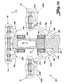
- FIGS 10 to 13 show a fourth embodiment of a agricultural machine (301) according to the present invention.
- This fourth example of realization differs from the previous embodiments described mainly at the level of the conveying devices (326a, 326b) equipping said lateral working units (5a, 5b).
- each device of conveying (326a, 326b) comprises an upper conveyor belt (330a, 330b) and a lower conveyor belt (331a, 331b).
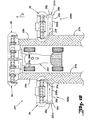
- said lower conveyor belts (331a, 331b) are now pivoting to said corresponding lateral working unit (5a, 5b) by means of a respective articulation (37a, 37b) of axis directed upwards.
- said lower conveyor belts (331a, 331b) can thus be pivoted in a substantially horizontal plane. Maneuvering devices are provided for this purpose. effect.
- Said upper conveyor belts (330a, 330b) of the fourth exemplary embodiment are similar to said upper conveyor belts (30a, 30b) of the first exemplary embodiment, they will therefore not be described more.
- said agricultural machine (301) groups the product cut in two swaths (27a, 27b).
- said lower conveyor belts (331a, 331b) remain positioned beneath said corresponding upper conveyor belts (330a, 330b).
- said lower conveyor belts (331a, 331b) are not not in contact with the cut product.
- said bands lower conveyors (331a, 331b) are not trained in this work configuration.
- the direction of scrolling of these bands conveyors (330a, 330b) is as shown in FIG.
- said agricultural machine (301) groups the cut product into a single swath (28).
- said lower conveyor belts (331a, 331b) are pivoted around said respective hinge (37a, 37b) towards a median vertical plane said carrier vehicle (303).
- the position of said articulation (37a, 37b) is such that said lower conveyor belts (331a, 331b) can, after pivoting, take the cut product from said conveyor belts corresponding upper ones (330a, 330b).
- Said conveyor belts lower (331a, 331b) and said upper conveyor belts (330a, 330b) are driven according to the scrolling direction shown in FIG.
- product cut by said work unit (5a, 5b) is thus first displaced by said upper conveyor belt (330a, 330b) and then by said belt lower conveyor (331a, 331b).
- Said lower conveyor belts (331a, 331b) are dimensioned so that said product cut by said corresponding lateral working unit (5a, 5b) is deposited immediately next to said half-swath (33) formed by said front work units (4a, 4b).
- the product cut by said front work units (4a, 4b) and by said lateral work units (5a, 5b) thus form said single swath (28).
- said lower conveyor belts (331a, 331b) advantageously make it possible to deposit said cut product behind said rear wheels (15b) of said carrier vehicle (303), even when said lateral workpieces (5a, 5b) are arranged in working position next to said vehicle carrier (303).
- each lower conveyor belt (331a, 331b) is in turn composed of a first conveyor belt (35a, 35b) and a second conveyor belt (36a, 36b).
- Said first band conveyor (35a, 35b) and said second conveyor belt (36a, 36b) are arranged in the extension of one another.
- said second band conveyor (36a, 36b) is pivotally connected to said first conveyor belt corresponding conveyor (35a, 35b) by means of a respective hinge (38a, 38b) of axis at least substantially horizontal.
- said first conveyor belt (35a, 35b) is substantially horizontal and said second conveyor belt (36a, 36b) is substantially vertical.
- a such a position makes it possible in particular to reduce the bulk of said device for conveying (326a, 326b).
- Said first conveyor belt (35a, 35b) is disposed at least partially below said conveyor belt corresponding upper part (330a, 330b) so as not to come into contact with said cut product. The cut product is therefore only transported by said upper conveyor belts (330a, 330b).
- said first conveyor belt (35a, 35b) remains substantially horizontal.
- said second conveyor belt (36a, 36b) is now rotated around said articulation (38a, 38b) so as to be substantially horizontal.
- the direction of scrolling of said first and second conveyor belts (35a, 35b, 36a, 36b) is as shown in FIG. 11.
- the cut product is therefore transported by said conveyor belts (330a, 330b) and then by said first conveyor belts (35a, 35b) and finally by said second conveyor belts (36a, 36b).
- the axis of said articulation respective (38a, 38b) coincides with the axis of rotation of one of said cylinders of said second corresponding conveyor belt (36a, 36b).
Landscapes
- Life Sciences & Earth Sciences (AREA)
- Environmental Sciences (AREA)
- Agricultural Machines (AREA)
- Harvester Elements (AREA)
- Harvesting Machines For Specific Crops (AREA)
- Soil Working Implements (AREA)
Description
- au moins deux unités de travail frontales disposées, lors du travail et vues suivant une direction d'avance, en avant dudit véhicule porteur, lesdites unités de travail frontales étant reliées à un dispositif d'attelage frontal du véhicule porteur permettant de les déplacer suivant une direction sensiblement verticale.
- la figure 1 représente, en vue de dessus et en position de travail, un premier exemple de réalisation d'un engin agricole selon la présente invention,
- la figure 2 représente, également en vue de dessus, le premier exemple de réalisation de la figure 1 en position de transport,
- la figure 3 représente, vu de derrière et à une autre échelle, le premier exemple de réalisation de la figure 1 en position de transport,
- la figure 4 représente, en vue de dessus, le premier exemple de réalisation de la figure 1 dans une première configuration de travail,
- la figure 5 représente, en vue de dessus, le premier exemple de réalisation de la figure 1 dans une deuxième configuration de travail,
- la figure 6 représente, en vue de dessus et en position de travail, un deuxième exemple de réalisation d'un engin agricole selon la présente invention,
- la figure 7 représente, en vue de dessus, le deuxième exemple de réalisation de la figure 6 en position de transport,
- la figure 8 représente, en vue de dessus, le deuxième exemple de réalisation de la figure 6 dans une configuration de travail,
- la figure 9 représente une vue partielle d'un troisième exemple de réalisation d'un engin agricole selon la présente invention en position de travail,
- la figure 10 représente, en vue de dessus, un quatrième exemple de réalisation selon la présente invention dans une première configuration de travail,
- la figure 11 représente, en vue de dessus, le quatrième exemple de réalisation de la figure 10 dans une deuxième configuration de travail,
- la figure 12 représente une vue partielle, de derrière et à une autre échelle, du quatrième exemple de réalisation dans la première configuration de travail,
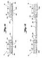
- la figure 13 représente une vue partielle, de derrière et à une autre échelle, du quatrième exemple de réalisation dans la deuxième configuration de travail.
- au moins deux unités de travail frontales (4a, 4b) disposées, lors du travail et vues suivant ladite direction d'avance (2), en avant dudit véhicule porteur (3), et
- au moins deux unités de travail latérales (5a, 5b) disposées, lors du travail, de part et d'autre d'une zone de travail (18) desdites unités de travail frontales (4a, 4b).
Claims (28)
- Engin agricole comportant un véhicule porteur (3 ; 103) et plusieurs unités de travail (4a, 4b, 5a, 5b) destinées à couper un produit sur pied, lesdites unités de travail (4a, 4b, 5a, 5b) étant liées audit véhicule porteur (3 ; 103), ledit engin agricole (1; 101) comportant:lesdites unités de travail frontales (4a, 4b) et lesdites unités de travail latérales (5a, 5b) pouvant être déplacées par rapport audit véhicule porteur (3 ; 103) de manière à occuper une position de transport ou une position de travail, caractérisé par le fait que lesdites unités de travail frontales (4a,4b) sont disposées, lors du travail et vues suivant une direction d'avance (2) dudit véhicule porteur (3 ; 103), en avant dudit véhicule porteur (3 ; 103), lesdites unités de travail frontales (4a, 4b) étant reliées à un dispositif d'attelage frontal (9) du véhicule porteur (3 ; 103) permettant de les déplacer suivant une direction sensiblement verticale.au moins deux unités de travail frontales (4a, 4b)au moins deux unités de travail latérales (5a, 5b) disposées, lors du travail, de part et d'autre d'une zone de travail (18) desdites unités de travail frontales (4a, 4b),
- Engin agricole selon la revendication 1, caractérisé par le fait que lors du travail et vues suivant ladite direction d'avance (2), lesdites unités de travail latérales (5a, 5b) sont disposées en arrière desdites unités de travail frontales (4a, 4b).
- Engin agricole selon la revendication 2, caractérisé par le fait que lors du travail et vues suivant ladite direction d'avance (2), lesdites unités de travail latérales (5a, 5b) sont disposées en arrière dudit véhicule porteur (3 ; 103).
- Engin agricole selon la revendication 2, caractérisé par le fait que lors du travail et vues suivant ladite direction d'avance (2), lesdites unités de travail latérales (5a, 5b) sont disposées sur les cotés dudit véhicule porteur (3 ; 103).
- Engin agricole selon l'une quelconque des revendications 1 à 4, caractérisé par le fait qu 'au moins une desdites unités de travail (4a, 4b, 5a, 5b) est liée de manière pivotante audit véhicule porteur (3 ; 103) au moyen d'une articulation respective (7a, 7b, 10a, 10b; 110a, 110b; 210a, 210b) d'axe dirigé suivant ladite direction d'avance (2) et qu'il est prévu des organes de manoeuvre destinés à pivoter ladite au moins une unité de travail (4a, 4b, 5a, 5b) autour de ladite articulation respective (7a, 7b, 10a, 10b; 110a, 110b; 210a, 210b) de ladite position de travail à ladite position de transport, et inversement.
- Engin agricole selon la revendication 5, caractérisé par le fait que ladite au moins une unité de travail (4a, 4b, 5a, 5b) est disposée :en position de travail, d'une manière au moins sensiblement horizontale, eten position de transport, d'une manière au moins sensiblement verticale.
- Engin agricole selon la revendication 5 ou 6, caractérisé par le fait qu 'au moins une desdites unités de travail frontales (4a, 4b) est liée au moyen de ladite articulation respective (7a, 7b) à une structure d'attelage (8), laquelle structure d'attelage (8) étant à son tour liée audit véhicule porteur (3).
- Engin agricole selon la revendication 7, caractérisé par le fait que ledit véhicule porteur (3 ; 103) comporte un dispositif d'attelage frontal (9) destiné à déplacer ladite structure d'attelage (8) suivant une direction sensiblement verticale.
- Engin agricole selon l'une quelconque des revendications 1 à 8, caractérisé par le fait qu 'au moins une desdites unités de travail (4a, 4b, 5a, 5b) est liée de manière coulissante audit véhicule porteur (3 ; 103) au moyen d'une articulation respective (11a, 11b; 211a, 211b) d'axe dirigé transversalement à ladite direction d'avance (2) et qu'il est prévu des organes de manoeuvre destinés à translater ladite au moins une unité de travail (4a, 4b, 5a, 5b) suivant ladite articulation respective (11a, 11b; 211a, 211b).
- Engin agricole selon l'une quelconque des revendications 5 à 8 pris en combinaison avec la revendication 9, caractérisé par le fait qu 'au moins une desdites unités de travail latérales (5a, 5b) est liée de manière coulissante au moyen de ladite articulation respective (11a, 11b) à un bras porteur respectif (12a, 12b), ledit bras porteur (12a, 12b) étant à son tour lié de manière pivotante au moyen de ladite articulation respective (10a, 10b; 110a, 110b) audit véhicule porteur (3).
- Engin agricole selon l'une quelconque des revendications 5 à 8 pris en combinaison avec la revendication 9, caractérisé par le fait qu' au moins une desdites unités de travail latérales (5a, 5b) est liée de manière pivotante au moyen de ladite articulation respective (210a, 210b) à un bras porteur respectif (212a, 212b), ledit bras porteur (212a, 212b) étant à son tour lié de manière coulissante au moyen de ladite articulation respective (211a, 211b) audit véhicule porteur (3).
- Engin agricole selon la revendication 10 ou 11, caractérisé par le fait que ledit bras porteur (12a, 12b; 212a, 212b) est lié au moyen de ladite articulation respective (10a, 10b; 211a, 211b) à une structure d'attelage (13), laquelle structure d'attelage (13) étant à son tour liée audit véhicule porteur (3).
- Engin agricole selon la revendication 12, caractérisé par le fait que ledit véhicule porteur (3) comporte un dispositif d'attelage arrière (14) destiné à déplacer ladite structure d'attelage (13) suivant une direction sensiblement verticale.
- Engin agricole selon l'une quelconque des revendications 1 à 13, caractérisé par le fait qu 'il comporte deux unités de travail frontales (4a, 4b).
- Engin agricole selon l'une quelconque des revendications 1 à 14, caractérisé par le fait qu 'il comporte deux unités de travail latérales (5a, 5b).
- Engin agricole selon l'une quelconque des revendications 1 à 15, caractérisé par le fait que ledit véhicule porteur (3 ; 103) comporte un dispositif de commande destiné à gérer de manière autonome le mouvement desdites unités de travail (4a, 4b, 5a, 5b) lors du passage de ladite position de transport à ladite position de travail, et inversement.
- Engin agricole selon l'une quelconque des revendications 1 à 16, caractérisé par le fait que chaque unité de travail (4a, 4b, 5a, 5b) comporte un dispositif de coupe respectif destiné à couper un produit sur pied et qu'au moins une desdites unités de travail (4a, 4b, 5a, 5b) comporte un dispositif de convoyage respectif (25a, 25b, 26a, 26b ; 326a, 326b) destiné à déplacer le produit coupé par le dispositif de coupe correspondant avant que ledit produit coupé ne touche le sol.
- Engin agricole selon la revendication 17, caractérisé par le fait qu' au moins une desdites unités de travail frontales (4a, 4b) comporte un dispositif de convoyage respectif (25a, 25b).
- Engin agricole selon la revendication 18, caractérisé par le fait que ledit dispositif de convoyage (25a, 25b) comporte une bande transporteuse (29a, 29b) disposée transversalement derrière ledit dispositif de coupe correspondant.
- Engin agricole selon la revendication 19, caractérisé par le fait qu 'il est prévu un moteur destiné à entraíner ladite bande transporteuse (29a, 29b) suivant deux sens de défilement.
- Engin agricole selon l'une quelconque des revendications 18 à 20, caractérisé par le fait que ledit dispositif de convoyage (25a, 25b) est lié de manière coulissante à ladite unité de travail frontale correspondante (4a, 4b) et qu'il est prévu des organes de manoeuvre destinés à translater ledit dispositif de convoyage (25a, 25b) horizontalement, vu en position de travail, et transversalement à ladite direction d'avance (2).
- Engin agricole selon l'une quelconque des revendications 17 à 21, caractérisé par le fait qu 'au moins une desdites unités de travail latérales (5a, 5b) comporte un dispositif de convoyage respectif (26a, 26b ; 326a, 326b).
- Engin agricole selon la revendication 22, caractérisé par le fait que ledit dispositif de convoyage (26a, 26b ; 326a, 326b) comporte une bande transporteuse supérieure (30a, 30b ; 330a, 330b) et une bande transporteuse inférieure (31a, 31b ; 331a, 331b), lesdites bandes transporteuses (30a, 31a; 30b, 31b; 330a, 331a ; 330b, 331b) étant disposées, au moins dans une position, l'une au-dessus de l'autre et transversalement derrière le dispositif de coupe correspondant.
- Engin agricole selon la revendication 23, caractérisé par le fait que ladite bande transporteuse inférieure (31a, 31b) est liée de manière coulissante à ladite unité de travail latérale correspondante (5a, 5b) et qu'il est prévu des organes de manoeuvre destinés à translater ladite bande transporteuse inférieure (31a, 31b) horizontalement, vu en position de travail, et transversalement à ladite direction d'avance (2).
- Engin agricole selon la revendication 23, caractérisé par le fait que ladite bande transporteuse inférieure (331a, 331b) est liée de manière pivotante à ladite unité de travail latérale correspondante (5a, 5b) au moyen d'une articulation (37a, 37b) d'axe dirigé vers le haut.
- Engin agricole selon la revendication 25, caractérisé par le fait que ladite bande transporteuse inférieure (331a, 331b) comporte une première bande transporteuse (35a, 35b) et une deuxième bande transporteuse (36a, 36b).
- Engin agricole selon la revendication 26, caractérisé par le fait que ladite deuxième bande transporteuse (36a, 36b) est liée de manière pivotante à ladite première bande transporteuse correspondante (35a, 35b) au moyen d'une articulation respective (38a, 38b) d'axe sensiblement horizontal.
- Engin agricole selon l'une quelconque des revendications 1 à 27, caractérisé par le fait que ledit véhicule porteur (3 ; 103) comporte deux roues arrières (15b), lesdites roues arrières (15b) étant liées de manière coulissante audit véhicule porteur (103) au moyen d'une articulation respective d'axe sensiblement horizontal et transversal à ladite direction d'avance (2), et qu'il est prévu des organes de manoeuvre destinés à translater chaque roue arrière (15b) suivant ladite articulation respective.
Applications Claiming Priority (3)
| Application Number | Priority Date | Filing Date | Title |
|---|---|---|---|
| FR0203893 | 2002-03-21 | ||
| FR0203893A FR2837347B1 (fr) | 2002-03-21 | 2002-03-21 | Faucheuse agricole comportant un vehicule porteur et plusieurs unites de travail |
| PCT/FR2003/000801 WO2003079761A1 (fr) | 2002-03-21 | 2003-03-13 | Faucheuse agricole comportant un vehicule porteur et plusieurs unites de travail |
Publications (2)
| Publication Number | Publication Date |
|---|---|
| EP1489896A1 EP1489896A1 (fr) | 2004-12-29 |
| EP1489896B1 true EP1489896B1 (fr) | 2005-09-07 |
Family
ID=27799278
Family Applications (1)
| Application Number | Title | Priority Date | Filing Date |
|---|---|---|---|
| EP03725285A Revoked EP1489896B1 (fr) | 2002-03-21 | 2003-03-13 | Faucheuse agricole comportant un vehicule porteur et plusieurs unites de travail |
Country Status (13)
| Country | Link |
|---|---|
| US (4) | US7500341B2 (fr) |
| EP (1) | EP1489896B1 (fr) |
| CN (2) | CN100405891C (fr) |
| AT (1) | ATE303716T1 (fr) |
| AU (1) | AU2003227831B2 (fr) |
| CA (1) | CA2479370C (fr) |
| DE (1) | DE60301566T2 (fr) |
| DK (1) | DK1489896T3 (fr) |
| FR (1) | FR2837347B1 (fr) |
| PL (1) | PL370592A1 (fr) |
| RU (1) | RU2305397C2 (fr) |
| UA (1) | UA77776C2 (fr) |
| WO (1) | WO2003079761A1 (fr) |
Cited By (1)
| Publication number | Priority date | Publication date | Assignee | Title |
|---|---|---|---|---|
| EP3666057A1 (fr) | 2018-12-14 | 2020-06-17 | Kverneland Group Kerteminde AS | Mécanisme de couplage de transporteur de récolte |
Families Citing this family (30)
| Publication number | Priority date | Publication date | Assignee | Title |
|---|---|---|---|---|
| FR2837347B1 (fr) * | 2002-03-21 | 2004-07-30 | Kuhn Sa | Faucheuse agricole comportant un vehicule porteur et plusieurs unites de travail |
| US7310929B2 (en) | 2003-03-31 | 2007-12-25 | Oxbo International Corporation | Windrow merging apparatus |
| FR2881609B1 (fr) | 2005-02-09 | 2007-03-09 | Kuhn Sa Sa | Engin agricole pour la coupe de produits comportant un vehicule porteur et des unites de travail |
| FR2885484B1 (fr) * | 2005-05-10 | 2007-06-15 | Kuhn Sa Sa | Engin agricole comportant un vehicule moteur et plusieurs unites de travail destinees a couper des produits vegetaux |
| DE102005050157A1 (de) * | 2005-10-19 | 2007-05-31 | Alois Pöttinger Maschinenfabrik Gmbh | Erntemaschine |
| EP2661169B1 (fr) * | 2011-01-03 | 2016-07-27 | Oxbo International Corporation | Andaineur automotrice |
| FR2974270B1 (fr) * | 2011-04-21 | 2014-04-04 | Kuhn Sa | Machine agricole avec un dispositif de repliage perfectionne |
| US8522517B2 (en) * | 2011-12-23 | 2013-09-03 | The Toro Company | Reel gang mower having different width front and rear cutting units |
| DK2789224T4 (en) | 2013-04-11 | 2018-10-08 | Kverneland Group Kerteminde As | Mower and mower unit |
| DE102013105073A1 (de) | 2013-05-17 | 2014-11-20 | Andreas Fröber | Mähwerksanordnung sowie Verfahren zur Erzeugung von Schwaden beim Mähen einer Fläche |
| SE537796C2 (sv) * | 2013-05-23 | 2015-10-20 | Imsson Natur Teknik Ab | Apparat och metod för att behandla en gröda |
| EP2829168B2 (fr) * | 2013-07-22 | 2024-06-12 | Kverneland Group Kerteminde AS | Tondeuse |
| FR3013557B1 (fr) * | 2013-11-22 | 2016-01-01 | Kuhn Sa | Machine agricole, notamment machine pour la recolte de vegetaux, comportant deux unites de travail animees articulees a un meme bras lateral |
| EP3329760B1 (fr) | 2013-12-23 | 2021-02-03 | Kverneland Group Kerteminde AS | Machine agricole |
| CA2890534C (fr) | 2014-05-08 | 2022-07-12 | Roc S.R.L. | Dispositif de recolte de produits agricoles longs et accessoire agricole autopropulse destine a la recolte de produits agricoles comportant ledit dispositif |
| DE102014114514A1 (de) | 2014-10-07 | 2016-04-07 | Claas Saulgau Gmbh | Landwirtschaftliches Arbeitsgerät und Verfahren zum Betreiben eines landwirtschaftlichen Arbeitsgeräts |
| DE102015002236A1 (de) * | 2015-02-20 | 2016-08-25 | Alois Pöttinger Maschinenfabrik Ges.m.b.H. | Heuwerbungsmaschine |
| US9999178B2 (en) | 2015-06-12 | 2018-06-19 | Oxbo International Corporation | Cam for a windrow merger and pickup head having a variable radius |
| US10356980B2 (en) * | 2016-10-28 | 2019-07-23 | Deere & Company | Work vehicle with wheel/track crop swath avoidance |
| US10085373B2 (en) | 2017-01-28 | 2018-10-02 | Neal Nuss | Harvester combine header assembly |
| US11382263B2 (en) * | 2018-02-19 | 2022-07-12 | Exmark Manufacturing Company, Incorporated | Articulating cutting deck |
| CN109168596B (zh) * | 2018-08-30 | 2021-04-30 | 绩溪袁稻农业产业科技有限公司 | 一种可收缩的玉米收割机 |
| NL2021519B1 (nl) * | 2018-08-30 | 2020-04-24 | Ploeger Oxbo Europe B V | Zelfrijdende landbouwmachine, bijvoorbeeld een zelfrijdende bandhark |
| GB2580976A (en) * | 2019-02-04 | 2020-08-05 | Kverneland Group Kerteminde As | A mower for an agricultural machine |
| GB201918841D0 (en) * | 2019-12-19 | 2020-02-05 | Agco Int Gmbh | Mower combination |
| GB201918845D0 (en) * | 2019-12-19 | 2020-02-05 | Agco Int Gmbh | Mower combination |
| GB201918843D0 (en) * | 2019-12-19 | 2020-02-05 | Agco Int Gmbh | Mower combination |
| GB202003486D0 (en) * | 2020-03-11 | 2020-04-29 | Agco Int Gmbh | Agricultural apparatus |
| GB202003487D0 (en) * | 2020-03-11 | 2020-04-29 | Agco Int Gmbh | Agricultural apparatus |
| GB202003488D0 (en) * | 2020-03-11 | 2020-04-29 | Agco Int Gmbh | Agricultural apparatus |
Family Cites Families (77)
| Publication number | Priority date | Publication date | Assignee | Title |
|---|---|---|---|---|
| US356311A (en) | 1887-01-18 | fosbery | ||
| US2099902A (en) * | 1931-08-05 | 1937-11-23 | Toro Mfg Corp | Tractor propelled gang lawn mower |
| US1961710A (en) * | 1932-03-02 | 1934-06-05 | Pol John Baptiste | Gang lawn mower |
| US3040502A (en) * | 1959-03-13 | 1962-06-26 | Smith Alexander | Tractor mower |
| US3070938A (en) * | 1960-06-20 | 1963-01-01 | Shunk Mfg Company | Grass mowers |
| US3177638A (en) * | 1960-09-30 | 1965-04-13 | Arthur L Johnson | Wide swath mower convertible for highway travel |
| US3371459A (en) * | 1963-11-26 | 1968-03-05 | Thomas | Mortar joint placement device |
| US3429109A (en) * | 1965-05-19 | 1969-02-25 | Jacobsen Mfg Co | Gang lawnmower |
| US3472005A (en) * | 1966-11-21 | 1969-10-14 | Jacobsen Mfg Co | Articularly mounted gang mowers on a tractor |
| GB1245092A (en) * | 1967-09-15 | 1971-09-02 | Ransomes Sims & Jefferies Ltd | Improvements in or relating to gang mower machines |
| NL6716443A (fr) * | 1967-12-04 | 1969-06-06 | ||
| US3616626A (en) * | 1968-02-14 | 1971-11-02 | Hahn Inc | Mower |
| US3563001A (en) | 1968-02-14 | 1971-02-16 | Cloud Machine Corp | Filling head for strip stock packaging machine |
| US3563011A (en) * | 1969-04-21 | 1971-02-16 | Kearney National Inc | Mower machine |
| US3608284A (en) * | 1970-04-09 | 1971-09-28 | Deere & Co | Gang mower |
| US3731469A (en) * | 1972-01-24 | 1973-05-08 | Jacobsen Mfg Co | Convertible gang lawn mower |
| US3808778A (en) | 1973-01-08 | 1974-05-07 | Jacobsen Mfg Co | Lawn mowers articularly supported on a tractor |
| NL7604451A (nl) * | 1976-04-27 | 1977-10-31 | Texas Industries Inc | Maaimachine. |
| US4304086A (en) * | 1979-08-27 | 1981-12-08 | Stuchl Ronald J | Lawn mower attachment for small tractors |
| CA1141177A (fr) * | 1980-10-17 | 1983-02-15 | William T. Arnold | Tondeuse seriees a mecanismes de relevage commun |
| US4395865A (en) * | 1981-01-28 | 1983-08-02 | Davis Jr Robert D | Self propelled lawn mower |
| US4497160A (en) * | 1983-04-29 | 1985-02-05 | Excel Industries, Inc. | Mower with lateral extension wings |
| DE3423410A1 (de) | 1983-06-23 | 1985-01-03 | Klaus 7964 Kißlegg Merk | Frontmaeher |
| US4512140A (en) * | 1983-09-16 | 1985-04-23 | Sperry Corporation | Stub draper drive for draper header |
| DE8433157U1 (de) | 1984-11-13 | 1986-10-02 | Niedermeier, Erwin, 8091 Emmering | Mähwerk |
| GB8501264D0 (en) * | 1985-01-18 | 1985-02-20 | Ransomes Sims & Jefferies Plc | Grass cutting attachment |
| CA1248763A (fr) * | 1985-01-23 | 1989-01-17 | Donald J.S. Wallis | Accessoire andaineur |
| CA1269848A (fr) * | 1986-04-30 | 1990-06-05 | William T. Arnold | Systeme collecteur de gazon pour tondeuse de pelouse |
| SU1436920A1 (ru) * | 1986-07-14 | 1988-11-15 | Ярославский моторный завод | Широкозахватный уборочный комплекс |
| US4769976A (en) * | 1987-02-11 | 1988-09-13 | The Toro Company | Method and apparatus for supporting a reel unit |
| US4854112A (en) * | 1987-09-04 | 1989-08-08 | The Toro Company | Turf maintenance apparatus |
| US4926621A (en) * | 1988-05-20 | 1990-05-22 | Torras Robert M | Mowing tractor with towed mower |
| US5042236A (en) * | 1990-02-08 | 1991-08-27 | The Toro Company | Cutting reel suspension with adjustable spring downloading |
| US5069022A (en) * | 1990-09-28 | 1991-12-03 | Befco, Inc. | Gang mower apparatus |
| DK283390A (da) | 1990-11-29 | 1992-05-30 | Taarup As Maskinfab | Skaarlaegger |
| US5133174A (en) * | 1991-01-28 | 1992-07-28 | Parsons Jr Ralph L | Hydraulically driven mowing unit |
| US5280695A (en) * | 1992-02-07 | 1994-01-25 | Nunes Manufacturing, Inc. | Wide area lawnmower |
| US5297378A (en) * | 1992-05-13 | 1994-03-29 | Deere & Company | Suspension mechanism for reel mowers |
| DE4322263C5 (de) | 1992-07-31 | 2009-04-23 | Claas Saulgau Gmbh | Verfahren zur Vorbereitung eines auf einer Bodenfläche fahrenden Arbeitsfahrzeuges mit einem Arbeitsgerät für den Straßenbetrieb und Arbeitsgerät zur Anordnung an einem solchen Arbeitsfahrzeug |
| DE9320343U1 (de) | 1992-07-31 | 1994-12-01 | Hans Wittrock GmbH, 26899 Rhede | Zur Anordnung an einem Arbeitsfahrzeug vorgesehenes Arbeitsgerät |
| US5343680A (en) * | 1992-09-03 | 1994-09-06 | Deere & Company | Suspension mechanism for reel mowers |
| DE4405858C1 (de) * | 1994-02-23 | 1995-06-01 | Fortschritt Erntemaschinen | Aufhängung für ein- oder beidseitig an einem Trägerfahrzeug angebrachte Arbeitsaggregate |
| DE4409113C1 (de) | 1994-03-17 | 1995-09-07 | Fortschritt Erntemaschinen | Lenkbewegliche Arbeitsaggregatekombination an einem frontgelenkten Trägerfahrzeug |
| US6082084A (en) * | 1995-11-13 | 2000-07-04 | Ransomes America Corporation | Electric riding mower with electric steering system |
| US5794422A (en) * | 1995-11-13 | 1998-08-18 | Ransomes America Corporation | Electric drive mower with motor generator set |
| US5813202A (en) * | 1996-05-13 | 1998-09-29 | Deere & Company | Impact absorbing mower deck mounting mechanism |
| US5715667A (en) * | 1996-05-13 | 1998-02-10 | Deere & Company | Wing deck mounting and lift mechanism |
| DE19620063C2 (de) | 1996-05-20 | 1999-10-14 | Krone Bernhard Gmbh Maschf | Aufhängung und Antriebsanordnung für ein- oder beidseitig an einem Trägerfahrzeug angebrachte Arbeitsaggregate |
| US5771669A (en) * | 1996-06-27 | 1998-06-30 | The Toro Company | Method and apparatus for mowing irregular turf areas |
| US5822960A (en) * | 1996-07-09 | 1998-10-20 | Kubota Corporation | Reel mower |
| US6336312B1 (en) * | 1997-02-03 | 2002-01-08 | Textron Inc. | Gang-Type rotary lawn mower with multiple rear rollers |
| US6047530A (en) * | 1997-02-03 | 2000-04-11 | Textron, Inc. | Gang-type rotary lawn mower |
| US6082086A (en) * | 1997-07-31 | 2000-07-04 | Kubota Corporation | Reel mower apparatus |
| US6032441A (en) * | 1997-11-13 | 2000-03-07 | The Toro Company | Triplex trim mower with laterally adjustable cutting units |
| SG80620A1 (en) | 1998-09-18 | 2001-05-22 | Samsung Electronics Co Ltd | Near-field optical storage medium and optical data storage system therefor |
| CN2362269Y (zh) * | 1998-12-17 | 2000-02-09 | 绥化市农机化技术推广站 | 大豆联合收割机仿形低割机构 |
| US6257357B1 (en) * | 1999-03-26 | 2001-07-10 | Deere & Company | Steering device for drive and steer transmission |
| DE19953380A1 (de) | 1999-03-31 | 2000-10-05 | Niemeyer Landmasch Gmbh | Selbstfahrende Mäheinheit |
| EP1040751A3 (fr) * | 1999-03-31 | 2002-04-10 | NIEMEYER Landmaschinen GmbH | Faucheuse automotrice |
| FR2792163B1 (fr) * | 1999-04-19 | 2001-06-29 | Ouest Agri | Perfectionnement aux faucheuses munies de moyens qui permettent le transfert lateral des andains de fourrage |
| DE19921957A1 (de) | 1999-05-14 | 2000-11-16 | Claas Saulgau Gmbh | Steuerung für landwirtschaftliche Arbeitsmaschine |
| DE19931684C1 (de) * | 1999-07-08 | 2000-09-07 | Krone Bernhard Gmbh Maschf | Gerätekombination zum Ernten von landwirtschaftlichem Halmgut |
| DE19932285A1 (de) * | 1999-07-10 | 2001-04-26 | Deere & Co | Selbstfahrendes Mähfahrzeug und Förderer |
| DE19951080A1 (de) * | 1999-10-23 | 2001-04-26 | Deere & Co | Selbstfahrendes landwirtschaftliches Fahrzeug |
| DE19959484A1 (de) * | 1999-12-10 | 2001-06-13 | Deere & Co | Mähgerät |
| US6389786B1 (en) * | 2000-02-18 | 2002-05-21 | The Toro Company | Belt drive system having a single drive motor for multi-bladed rotary cutting unit for mower |
| DE10121014A1 (de) * | 2001-04-28 | 2002-11-21 | Deere & Co | Mähvorrichtung |
| DE20108319U1 (de) * | 2001-05-17 | 2001-08-16 | Maschinenfabrik Bernard Krone GmbH, 48480 Spelle | Arbeitsaggregatekombination |
| DE10138445A1 (de) * | 2001-08-04 | 2003-02-13 | Deere & Co | Vorrichtung mit einem Aufnehmer, einem Förderer und einem Anschlussmittel zur Verbindung mit einem Fahrzeug |
| DE10151571A1 (de) | 2001-10-23 | 2003-04-30 | Claas Saulgau Gmbh | Verfahren zur Optimierung der Erzeugung von qualitativ hochwertigem Futter |
| DE10206507A1 (de) * | 2002-02-16 | 2003-08-28 | Deere & Co | Einrichtung zum Bewegen einer Arbeitseinheit |
| FR2837347B1 (fr) | 2002-03-21 | 2004-07-30 | Kuhn Sa | Faucheuse agricole comportant un vehicule porteur et plusieurs unites de travail |
| DE10234741A1 (de) * | 2002-07-30 | 2004-02-19 | Claas Saulgau Gmbh | Anlenkung eines Seitenmähwerks und seiner Zusatzeinrichtungen an ein Tragwerk zur Ankopplung an einen Traktor oder an ein Trägerfahrzeug |
| ATE413092T1 (de) * | 2002-10-06 | 2008-11-15 | Claas Saulgau Gmbh | Selbstfahrendes grossflächenmähwerk |
| US6860335B2 (en) * | 2002-12-19 | 2005-03-01 | Great Plains Manufacturing, Incorporated | Front folding agricultural implement |
| DE10317816A1 (de) * | 2003-04-16 | 2004-11-04 | Claas Selbstfahrende Erntemaschinen Gmbh | Feldhäcksler mit positionierbarer Fahrerkabine |
| FR2881609B1 (fr) * | 2005-02-09 | 2007-03-09 | Kuhn Sa Sa | Engin agricole pour la coupe de produits comportant un vehicule porteur et des unites de travail |
-
2002
- 2002-03-21 FR FR0203893A patent/FR2837347B1/fr not_active Expired - Fee Related
-
2003
- 2003-03-13 EP EP03725285A patent/EP1489896B1/fr not_active Revoked
- 2003-03-13 US US10/506,675 patent/US7500341B2/en not_active Expired - Fee Related
- 2003-03-13 CN CNB038066076A patent/CN100405891C/zh not_active Expired - Fee Related
- 2003-03-13 DK DK03725285T patent/DK1489896T3/da active
- 2003-03-13 UA UA20041008454A patent/UA77776C2/uk unknown
- 2003-03-13 AT AT03725285T patent/ATE303716T1/de active
- 2003-03-13 WO PCT/FR2003/000801 patent/WO2003079761A1/fr not_active Ceased
- 2003-03-13 RU RU2004131192/12A patent/RU2305397C2/ru not_active IP Right Cessation
- 2003-03-13 DE DE60301566T patent/DE60301566T2/de not_active Revoked
- 2003-03-13 AU AU2003227831A patent/AU2003227831B2/en not_active Ceased
- 2003-03-13 CN CN2008101358691A patent/CN101310583B/zh not_active Expired - Fee Related
- 2003-03-13 CA CA2479370A patent/CA2479370C/fr not_active Expired - Fee Related
- 2003-03-13 PL PL03370592A patent/PL370592A1/xx unknown
-
2009
- 2009-01-27 US US12/360,185 patent/US8074432B2/en not_active Expired - Fee Related
-
2011
- 2011-09-23 US US13/243,720 patent/US8225588B2/en not_active Expired - Fee Related
- 2011-09-23 US US13/243,830 patent/US8220233B2/en not_active Expired - Fee Related
Cited By (2)
| Publication number | Priority date | Publication date | Assignee | Title |
|---|---|---|---|---|
| EP3666057A1 (fr) | 2018-12-14 | 2020-06-17 | Kverneland Group Kerteminde AS | Mécanisme de couplage de transporteur de récolte |
| WO2020120680A1 (fr) | 2018-12-14 | 2020-06-18 | Kverneland Kerteminde A/S | Mécanisme d'accouplement de transporteur de récolte |
Also Published As
| Publication number | Publication date |
|---|---|
| CN1642408A (zh) | 2005-07-20 |
| RU2305397C2 (ru) | 2007-09-10 |
| CN101310583A (zh) | 2008-11-26 |
| WO2003079761A1 (fr) | 2003-10-02 |
| US8225588B2 (en) | 2012-07-24 |
| ATE303716T1 (de) | 2005-09-15 |
| US20120060458A1 (en) | 2012-03-15 |
| CA2479370C (fr) | 2011-07-12 |
| CN101310583B (zh) | 2010-11-03 |
| US20090133372A1 (en) | 2009-05-28 |
| FR2837347A1 (fr) | 2003-09-26 |
| DE60301566D1 (de) | 2005-10-13 |
| DK1489896T3 (da) | 2006-01-16 |
| CN100405891C (zh) | 2008-07-30 |
| UA77776C2 (uk) | 2007-01-15 |
| RU2004131192A (ru) | 2005-05-20 |
| AU2003227831A1 (en) | 2003-10-08 |
| PL370592A1 (en) | 2005-05-30 |
| DE60301566T2 (de) | 2006-06-14 |
| US20120060459A1 (en) | 2012-03-15 |
| US20050252183A1 (en) | 2005-11-17 |
| US8074432B2 (en) | 2011-12-13 |
| EP1489896A1 (fr) | 2004-12-29 |
| FR2837347B1 (fr) | 2004-07-30 |
| AU2003227831B2 (en) | 2009-10-08 |
| US8220233B2 (en) | 2012-07-17 |
| CA2479370A1 (fr) | 2003-10-02 |
| US7500341B2 (en) | 2009-03-10 |
Similar Documents
| Publication | Publication Date | Title |
|---|---|---|
| CA2479370C (fr) | Faucheuse agricole comportant un vehicule porteur et plusieurs unites de travail | |
| EP1690446B1 (fr) | Engin agricole pour la coupe de produits | |
| EP1366650B1 (fr) | Machine agricole comportant un dispositif de mise en transport | |
| BE1028807B1 (nl) | Verwerkingsmachine en werkwijze voor het verwerken van vezelplanten | |
| EP1615490B1 (fr) | Faucheuse agricole | |
| FR2696898A1 (fr) | Faucheuse avec un entraînement perfectionné des rouleaux de traitement. | |
| CA2284379C (fr) | Machine agricole comportant un timon pivotable et des organes de transmission comprenant un accouplement a joints universels | |
| FR2458420A1 (fr) | Tracteur a transmission hydraulique | |
| EP0861581A1 (fr) | Machine agricole de coupe comportant un dispositif de suspension perfectionné du mécanisme de coupe | |
| FR2860386A1 (fr) | Appareil collecteur d'herbe et tondeuse le comportant | |
| CA2380681C (fr) | Machine de fenaison | |
| CA3248092A1 (fr) | Machine de fenaison avec convoyeurs et procede de fonctionnement | |
| EP1554921B1 (fr) | Machine de coupe | |
| EP1434476B1 (fr) | Machine agricole, notamment du type faucheuse rotative, comportant un dispositif de coupe amelioree | |
| CA2543190C (fr) | Engin agricole comportant un vehicule moteur et plusieurs unites de travail destinees a couper des produits vegetaux | |
| EP1250833B1 (fr) | Faucheuse agricole comportant un mécanisme de regroupement d'andains | |
| NL8901717A (nl) | Rooier. | |
| NL2011697C2 (en) | Agricultural vehicle adapted for curve driving. | |
| EP2659766B1 (fr) | Taille haie à conducteur marchant | |
| FR2504351A1 (fr) | Machine automotrice pour recolter des tomates ou d'autres legumes analogues | |
| JPH10113034A (ja) | 農産物収穫機 |
Legal Events
| Date | Code | Title | Description |
|---|---|---|---|
| PUAI | Public reference made under article 153(3) epc to a published international application that has entered the european phase |
Free format text: ORIGINAL CODE: 0009012 |
|
| 17P | Request for examination filed |
Effective date: 20041021 |
|
| AK | Designated contracting states |
Kind code of ref document: A1 Designated state(s): AT BE BG CH CY CZ DE DK EE ES FI FR GB GR HU IE IT LI LU MC NL PT RO SE SI SK TR |
|
| GRAP | Despatch of communication of intention to grant a patent |
Free format text: ORIGINAL CODE: EPIDOSNIGR1 |
|
| 17Q | First examination report despatched |
Effective date: 20050119 |
|
| RIN1 | Information on inventor provided before grant (corrected) |
Inventor name: STUTZMANN, OLIVIER Inventor name: HIRONIMUS, JEANNOT Inventor name: BONNIN, DAVID Inventor name: NEUERBURG, HORST |
|
| GRAS | Grant fee paid |
Free format text: ORIGINAL CODE: EPIDOSNIGR3 |
|
| GRAA | (expected) grant |
Free format text: ORIGINAL CODE: 0009210 |
|
| AK | Designated contracting states |
Kind code of ref document: B1 Designated state(s): AT BE BG CH CY CZ DE DK EE ES FI FR GB GR HU IE IT LI LU MC NL PT RO SE SI SK TR |
|
| PG25 | Lapsed in a contracting state [announced via postgrant information from national office to epo] |
Ref country code: SI Free format text: LAPSE BECAUSE OF FAILURE TO SUBMIT A TRANSLATION OF THE DESCRIPTION OR TO PAY THE FEE WITHIN THE PRESCRIBED TIME-LIMIT Effective date: 20050907 Ref country code: FI Free format text: LAPSE BECAUSE OF FAILURE TO SUBMIT A TRANSLATION OF THE DESCRIPTION OR TO PAY THE FEE WITHIN THE PRESCRIBED TIME-LIMIT Effective date: 20050907 Ref country code: RO Free format text: LAPSE BECAUSE OF FAILURE TO SUBMIT A TRANSLATION OF THE DESCRIPTION OR TO PAY THE FEE WITHIN THE PRESCRIBED TIME-LIMIT Effective date: 20050907 Ref country code: IE Free format text: LAPSE BECAUSE OF FAILURE TO SUBMIT A TRANSLATION OF THE DESCRIPTION OR TO PAY THE FEE WITHIN THE PRESCRIBED TIME-LIMIT Effective date: 20050907 Ref country code: SK Free format text: LAPSE BECAUSE OF FAILURE TO SUBMIT A TRANSLATION OF THE DESCRIPTION OR TO PAY THE FEE WITHIN THE PRESCRIBED TIME-LIMIT Effective date: 20050907 |
|
| REG | Reference to a national code |
Ref country code: GB Ref legal event code: FG4D Free format text: NOT ENGLISH |
|
| REG | Reference to a national code |
Ref country code: CH Ref legal event code: EP |
|
| REG | Reference to a national code |
Ref country code: IE Ref legal event code: FG4D Free format text: LANGUAGE OF EP DOCUMENT: FRENCH |
|
| REF | Corresponds to: |
Ref document number: 60301566 Country of ref document: DE Date of ref document: 20051013 Kind code of ref document: P |
|
| PG25 | Lapsed in a contracting state [announced via postgrant information from national office to epo] |
Ref country code: SE Free format text: LAPSE BECAUSE OF FAILURE TO SUBMIT A TRANSLATION OF THE DESCRIPTION OR TO PAY THE FEE WITHIN THE PRESCRIBED TIME-LIMIT Effective date: 20051207 Ref country code: GR Free format text: LAPSE BECAUSE OF FAILURE TO SUBMIT A TRANSLATION OF THE DESCRIPTION OR TO PAY THE FEE WITHIN THE PRESCRIBED TIME-LIMIT Effective date: 20051207 Ref country code: BG Free format text: LAPSE BECAUSE OF FAILURE TO SUBMIT A TRANSLATION OF THE DESCRIPTION OR TO PAY THE FEE WITHIN THE PRESCRIBED TIME-LIMIT Effective date: 20051207 |
|
| PG25 | Lapsed in a contracting state [announced via postgrant information from national office to epo] |
Ref country code: ES Free format text: LAPSE BECAUSE OF FAILURE TO SUBMIT A TRANSLATION OF THE DESCRIPTION OR TO PAY THE FEE WITHIN THE PRESCRIBED TIME-LIMIT Effective date: 20051218 |
|
| GBT | Gb: translation of ep patent filed (gb section 77(6)(a)/1977) |
Effective date: 20051128 |
|
| REG | Reference to a national code |
Ref country code: DK Ref legal event code: T3 |
|
| PG25 | Lapsed in a contracting state [announced via postgrant information from national office to epo] |
Ref country code: PT Free format text: LAPSE BECAUSE OF FAILURE TO SUBMIT A TRANSLATION OF THE DESCRIPTION OR TO PAY THE FEE WITHIN THE PRESCRIBED TIME-LIMIT Effective date: 20060207 |
|
| PG25 | Lapsed in a contracting state [announced via postgrant information from national office to epo] |
Ref country code: HU Free format text: LAPSE BECAUSE OF FAILURE TO SUBMIT A TRANSLATION OF THE DESCRIPTION OR TO PAY THE FEE WITHIN THE PRESCRIBED TIME-LIMIT Effective date: 20060308 |
|
| PG25 | Lapsed in a contracting state [announced via postgrant information from national office to epo] |
Ref country code: LU Free format text: LAPSE BECAUSE OF NON-PAYMENT OF DUE FEES Effective date: 20060331 Ref country code: BE Free format text: LAPSE BECAUSE OF NON-PAYMENT OF DUE FEES Effective date: 20060331 Ref country code: MC Free format text: LAPSE BECAUSE OF NON-PAYMENT OF DUE FEES Effective date: 20060331 |
|
| REG | Reference to a national code |
Ref country code: IE Ref legal event code: FD4D |
|
| PLBI | Opposition filed |
Free format text: ORIGINAL CODE: 0009260 |
|
| PLBI | Opposition filed |
Free format text: ORIGINAL CODE: 0009260 |
|
| 26 | Opposition filed |
Opponent name: OCTROOIBUREAU VAN DER LELY N.V. Effective date: 20060519 |
|
| PLAX | Notice of opposition and request to file observation + time limit sent |
Free format text: ORIGINAL CODE: EPIDOSNOBS2 |
|
| 26 | Opposition filed |
Opponent name: OCTROOIBUREAU VAN DER LELY N.V. Effective date: 20060519 Opponent name: CLAAS SAULGAU GMBH Effective date: 20060607 Opponent name: MASCHINENFABRIK BERNARD KRONE GMBH Effective date: 20060607 |
|
| NLR1 | Nl: opposition has been filed with the epo |
Opponent name: OCTROOIBUREAU VAN DER LELY N.V. Opponent name: MASCHINENFABRIK BERNARD KRONE GMBH Opponent name: CLAAS SAULGAU GMBH |
|
| PLAF | Information modified related to communication of a notice of opposition and request to file observations + time limit |
Free format text: ORIGINAL CODE: EPIDOSCOBS2 |
|
| PLBB | Reply of patent proprietor to notice(s) of opposition received |
Free format text: ORIGINAL CODE: EPIDOSNOBS3 |
|
| REG | Reference to a national code |
Ref country code: CH Ref legal event code: PL |
|
| BERE | Be: lapsed |
Owner name: KUHN S.A. Effective date: 20060331 |
|
| PG25 | Lapsed in a contracting state [announced via postgrant information from national office to epo] |
Ref country code: LI Free format text: LAPSE BECAUSE OF NON-PAYMENT OF DUE FEES Effective date: 20070331 Ref country code: CH Free format text: LAPSE BECAUSE OF NON-PAYMENT OF DUE FEES Effective date: 20070331 |
|
| APBP | Date of receipt of notice of appeal recorded |
Free format text: ORIGINAL CODE: EPIDOSNNOA2O |
|
| APAH | Appeal reference modified |
Free format text: ORIGINAL CODE: EPIDOSCREFNO |
|
| PG25 | Lapsed in a contracting state [announced via postgrant information from national office to epo] |
Ref country code: EE Free format text: LAPSE BECAUSE OF FAILURE TO SUBMIT A TRANSLATION OF THE DESCRIPTION OR TO PAY THE FEE WITHIN THE PRESCRIBED TIME-LIMIT Effective date: 20050907 |
|
| APAJ | Date of receipt of notice of appeal modified |
Free format text: ORIGINAL CODE: EPIDOSCNOA2O |
|
| APBP | Date of receipt of notice of appeal recorded |
Free format text: ORIGINAL CODE: EPIDOSNNOA2O |
|
| PG25 | Lapsed in a contracting state [announced via postgrant information from national office to epo] |
Ref country code: TR Free format text: LAPSE BECAUSE OF FAILURE TO SUBMIT A TRANSLATION OF THE DESCRIPTION OR TO PAY THE FEE WITHIN THE PRESCRIBED TIME-LIMIT Effective date: 20050907 |
|
| APBQ | Date of receipt of statement of grounds of appeal recorded |
Free format text: ORIGINAL CODE: EPIDOSNNOA3O |
|
| APBQ | Date of receipt of statement of grounds of appeal recorded |
Free format text: ORIGINAL CODE: EPIDOSNNOA3O |
|
| PLAB | Opposition data, opponent's data or that of the opponent's representative modified |
Free format text: ORIGINAL CODE: 0009299OPPO |
|
| PG25 | Lapsed in a contracting state [announced via postgrant information from national office to epo] |
Ref country code: CY Free format text: LAPSE BECAUSE OF FAILURE TO SUBMIT A TRANSLATION OF THE DESCRIPTION OR TO PAY THE FEE WITHIN THE PRESCRIBED TIME-LIMIT Effective date: 20050907 |
|
| PGFP | Annual fee paid to national office [announced via postgrant information from national office to epo] |
Ref country code: AT Payment date: 20090220 Year of fee payment: 7 Ref country code: DK Payment date: 20090224 Year of fee payment: 7 |
|
| PGFP | Annual fee paid to national office [announced via postgrant information from national office to epo] |
Ref country code: CZ Payment date: 20090224 Year of fee payment: 7 Ref country code: NL Payment date: 20090223 Year of fee payment: 7 |
|
| PGFP | Annual fee paid to national office [announced via postgrant information from national office to epo] |
Ref country code: GB Payment date: 20090225 Year of fee payment: 7 |
|
| PGFP | Annual fee paid to national office [announced via postgrant information from national office to epo] |
Ref country code: DE Payment date: 20090327 Year of fee payment: 7 Ref country code: FR Payment date: 20090327 Year of fee payment: 7 Ref country code: IT Payment date: 20090314 Year of fee payment: 7 |
|
| APBU | Appeal procedure closed |
Free format text: ORIGINAL CODE: EPIDOSNNOA9O |
|
| RDAF | Communication despatched that patent is revoked |
Free format text: ORIGINAL CODE: EPIDOSNREV1 |
|
| RDAG | Patent revoked |
Free format text: ORIGINAL CODE: 0009271 |
|
| STAA | Information on the status of an ep patent application or granted ep patent |
Free format text: STATUS: PATENT REVOKED |
|
| 27W | Patent revoked |
Effective date: 20100112 |
|
| GBPR | Gb: patent revoked under art. 102 of the ep convention designating the uk as contracting state |
Effective date: 20100112 |