EP1489679B1 - Sekundärbatterie - Google Patents
Sekundärbatterie Download PDFInfo
- Publication number
- EP1489679B1 EP1489679B1 EP04002241.0A EP04002241A EP1489679B1 EP 1489679 B1 EP1489679 B1 EP 1489679B1 EP 04002241 A EP04002241 A EP 04002241A EP 1489679 B1 EP1489679 B1 EP 1489679B1
- Authority
- EP
- European Patent Office
- Prior art keywords
- cell
- electrode
- secondary battery
- shaft
- edge portion
- Prior art date
- Legal status (The legal status is an assumption and is not a legal conclusion. Google has not performed a legal analysis and makes no representation as to the accuracy of the status listed.)
- Expired - Lifetime
Links
- 238000002788 crimping Methods 0.000 claims description 17
- 238000003466 welding Methods 0.000 claims description 16
- 238000004519 manufacturing process Methods 0.000 description 73
- 238000004804 winding Methods 0.000 description 53
- 238000000034 method Methods 0.000 description 41
- 239000008151 electrolyte solution Substances 0.000 description 29
- 238000009413 insulation Methods 0.000 description 29
- 238000010276 construction Methods 0.000 description 15
- 238000007789 sealing Methods 0.000 description 10
- 239000000853 adhesive Substances 0.000 description 8
- 230000001070 adhesive effect Effects 0.000 description 8
- 238000010586 diagram Methods 0.000 description 7
- 238000005304 joining Methods 0.000 description 5
- 239000002826 coolant Substances 0.000 description 4
- 239000007773 negative electrode material Substances 0.000 description 4
- 239000007774 positive electrode material Substances 0.000 description 4
- KWYUFKZDYYNOTN-UHFFFAOYSA-M Potassium hydroxide Chemical compound [OH-].[K+] KWYUFKZDYYNOTN-UHFFFAOYSA-M 0.000 description 3
- 238000001816 cooling Methods 0.000 description 3
- 239000000463 material Substances 0.000 description 3
- PXHVJJICTQNCMI-UHFFFAOYSA-N nickel Substances [Ni] PXHVJJICTQNCMI-UHFFFAOYSA-N 0.000 description 3
- 238000003825 pressing Methods 0.000 description 3
- 239000011347 resin Substances 0.000 description 3
- 229920005989 resin Polymers 0.000 description 3
- 239000007787 solid Substances 0.000 description 3
- HBBGRARXTFLTSG-UHFFFAOYSA-N Lithium ion Chemical compound [Li+] HBBGRARXTFLTSG-UHFFFAOYSA-N 0.000 description 2
- QAOWNCQODCNURD-UHFFFAOYSA-N Sulfuric acid Chemical compound OS(O)(=O)=O QAOWNCQODCNURD-UHFFFAOYSA-N 0.000 description 2
- 230000015556 catabolic process Effects 0.000 description 2
- 230000007423 decrease Effects 0.000 description 2
- 238000006731 degradation reaction Methods 0.000 description 2
- 239000011888 foil Substances 0.000 description 2
- 238000002347 injection Methods 0.000 description 2
- 239000007924 injection Substances 0.000 description 2
- 150000002500 ions Chemical class 0.000 description 2
- 229910001416 lithium ion Inorganic materials 0.000 description 2
- 229910052759 nickel Inorganic materials 0.000 description 2
- 238000002360 preparation method Methods 0.000 description 2
- 229910000878 H alloy Inorganic materials 0.000 description 1
- WHXSMMKQMYFTQS-UHFFFAOYSA-N Lithium Chemical compound [Li] WHXSMMKQMYFTQS-UHFFFAOYSA-N 0.000 description 1
- 239000011149 active material Substances 0.000 description 1
- 239000011248 coating agent Substances 0.000 description 1
- 238000000576 coating method Methods 0.000 description 1
- 239000004020 conductor Substances 0.000 description 1
- 239000003792 electrolyte Substances 0.000 description 1
- 230000020169 heat generation Effects 0.000 description 1
- 229910052739 hydrogen Inorganic materials 0.000 description 1
- 239000001257 hydrogen Substances 0.000 description 1
- 238000007689 inspection Methods 0.000 description 1
- 239000007788 liquid Substances 0.000 description 1
- 229910052744 lithium Inorganic materials 0.000 description 1
- 229910052751 metal Inorganic materials 0.000 description 1
- 239000002184 metal Substances 0.000 description 1
- -1 nickel hydrogen Chemical class 0.000 description 1
- 239000004745 nonwoven fabric Substances 0.000 description 1
- 230000002093 peripheral effect Effects 0.000 description 1
- 229920003023 plastic Polymers 0.000 description 1
- 229920000747 poly(lactic acid) Polymers 0.000 description 1
- 229920000642 polymer Polymers 0.000 description 1
- 239000005518 polymer electrolyte Substances 0.000 description 1
- 238000004549 pulsed laser deposition Methods 0.000 description 1
- 230000001105 regulatory effect Effects 0.000 description 1
- 238000007665 sagging Methods 0.000 description 1
- 238000000926 separation method Methods 0.000 description 1
Images








Classifications
-
- F—MECHANICAL ENGINEERING; LIGHTING; HEATING; WEAPONS; BLASTING
- F16—ENGINEERING ELEMENTS AND UNITS; GENERAL MEASURES FOR PRODUCING AND MAINTAINING EFFECTIVE FUNCTIONING OF MACHINES OR INSTALLATIONS; THERMAL INSULATION IN GENERAL
- F16K—VALVES; TAPS; COCKS; ACTUATING-FLOATS; DEVICES FOR VENTING OR AERATING
- F16K31/00—Actuating devices; Operating means; Releasing devices
- F16K31/12—Actuating devices; Operating means; Releasing devices actuated by fluid
- F16K31/18—Actuating devices; Operating means; Releasing devices actuated by fluid actuated by a float
-
- H—ELECTRICITY
- H01—ELECTRIC ELEMENTS
- H01M—PROCESSES OR MEANS, e.g. BATTERIES, FOR THE DIRECT CONVERSION OF CHEMICAL ENERGY INTO ELECTRICAL ENERGY
- H01M10/00—Secondary cells; Manufacture thereof
- H01M10/04—Construction or manufacture in general
- H01M10/0404—Machines for assembling batteries
-
- F—MECHANICAL ENGINEERING; LIGHTING; HEATING; WEAPONS; BLASTING
- F16—ENGINEERING ELEMENTS AND UNITS; GENERAL MEASURES FOR PRODUCING AND MAINTAINING EFFECTIVE FUNCTIONING OF MACHINES OR INSTALLATIONS; THERMAL INSULATION IN GENERAL
- F16K—VALVES; TAPS; COCKS; ACTUATING-FLOATS; DEVICES FOR VENTING OR AERATING
- F16K24/00—Devices, e.g. valves, for venting or aerating enclosures
-
- F—MECHANICAL ENGINEERING; LIGHTING; HEATING; WEAPONS; BLASTING
- F16—ENGINEERING ELEMENTS AND UNITS; GENERAL MEASURES FOR PRODUCING AND MAINTAINING EFFECTIVE FUNCTIONING OF MACHINES OR INSTALLATIONS; THERMAL INSULATION IN GENERAL
- F16K—VALVES; TAPS; COCKS; ACTUATING-FLOATS; DEVICES FOR VENTING OR AERATING
- F16K47/00—Means in valves for absorbing fluid energy
- F16K47/02—Means in valves for absorbing fluid energy for preventing water-hammer or noise
- F16K47/023—Means in valves for absorbing fluid energy for preventing water-hammer or noise for preventing water-hammer, e.g. damping of the valve movement
-
- H—ELECTRICITY
- H01—ELECTRIC ELEMENTS
- H01M—PROCESSES OR MEANS, e.g. BATTERIES, FOR THE DIRECT CONVERSION OF CHEMICAL ENERGY INTO ELECTRICAL ENERGY
- H01M10/00—Secondary cells; Manufacture thereof
- H01M10/04—Construction or manufacture in general
- H01M10/0431—Cells with wound or folded electrodes
-
- H—ELECTRICITY
- H01—ELECTRIC ELEMENTS
- H01M—PROCESSES OR MEANS, e.g. BATTERIES, FOR THE DIRECT CONVERSION OF CHEMICAL ENERGY INTO ELECTRICAL ENERGY
- H01M4/00—Electrodes
- H01M4/02—Electrodes composed of, or comprising, active material
- H01M4/04—Processes of manufacture in general
- H01M4/043—Processes of manufacture in general involving compressing or compaction
- H01M4/0435—Rolling or calendering
-
- Y—GENERAL TAGGING OF NEW TECHNOLOGICAL DEVELOPMENTS; GENERAL TAGGING OF CROSS-SECTIONAL TECHNOLOGIES SPANNING OVER SEVERAL SECTIONS OF THE IPC; TECHNICAL SUBJECTS COVERED BY FORMER USPC CROSS-REFERENCE ART COLLECTIONS [XRACs] AND DIGESTS
- Y02—TECHNOLOGIES OR APPLICATIONS FOR MITIGATION OR ADAPTATION AGAINST CLIMATE CHANGE
- Y02E—REDUCTION OF GREENHOUSE GAS [GHG] EMISSIONS, RELATED TO ENERGY GENERATION, TRANSMISSION OR DISTRIBUTION
- Y02E60/00—Enabling technologies; Technologies with a potential or indirect contribution to GHG emissions mitigation
- Y02E60/10—Energy storage using batteries
-
- Y—GENERAL TAGGING OF NEW TECHNOLOGICAL DEVELOPMENTS; GENERAL TAGGING OF CROSS-SECTIONAL TECHNOLOGIES SPANNING OVER SEVERAL SECTIONS OF THE IPC; TECHNICAL SUBJECTS COVERED BY FORMER USPC CROSS-REFERENCE ART COLLECTIONS [XRACs] AND DIGESTS
- Y02—TECHNOLOGIES OR APPLICATIONS FOR MITIGATION OR ADAPTATION AGAINST CLIMATE CHANGE
- Y02P—CLIMATE CHANGE MITIGATION TECHNOLOGIES IN THE PRODUCTION OR PROCESSING OF GOODS
- Y02P70/00—Climate change mitigation technologies in the production process for final industrial or consumer products
- Y02P70/50—Manufacturing or production processes characterised by the final manufactured product
Definitions
- the invention relates to a secondary battery and a manufacturing system and method therefor. More particularly, the invention relates to a secondary battery in which a plurality of cells are connected together in one direction, and a manufacturing system and method therefor.
- a cylindrical, sealed nickel hydrogen secondary battery having a construction such as that shown in FIG. 14 is known, for example ( Electric Vehicle Handbook (2001), Electric Vehicle Handbook, pp. 261-262, Maruzen ).
- a secondary battery 1400 includes a case 1410, a positive electrode collector 1420, a positive electrode plate 1422, a negative electrode collector 1430, a negative electrode plate 1432, a separator 1440, an insulation gasket 1450, a cap 1460, a safety valve 1470, a sealing plate 1480, and an insulation ring 1490.
- the cap 1460 is the positive electrode and the case 1410 is the negative electrode.
- JP(A) 4-341766 discloses a wound multiple-cell, sealed secondary battery that improves the efficiency of the secondary battery by reducing voltage loss between cells and inhibits the active material utilization rate from falling at the outer periphery of the battery.
- This secondary battery is provided with a bipolar electrode plate, a first cell electrode plate and an end electrode plate.
- the bipolar electrode plate includes positive and negative electrode active material to the left and right of a single band-shaped collector.
- the bipolar electrode plate also has a protruding member that separates the cells at the center portion of the collector.
- the first cell electrode plate and the end cell electrode plate include a positive or negative electrode active material provided on either the left or the right of a predetermined portion of the single band-shaped collector.
- US 6,287,719 B1 that includes a housing and a spiral-wound electrode assembly disposed in the housing and defining at least two electrochemical cells that are electrically connected in series.
- the cells include wound layers of a positive electrode, a negative electrode, and a polymer electrolyte provided between the positive and negative electrode layers.
- the layers of each successive electrochemical cell are wound around the layers of the previous cell and are preferably separated therefrom by an insulating layer.
- a charging element device comprising columnar charging element modules arranged by serially connecting cylindrical cells via an insulating ring is disclosed in US 6,340,877 B1 .
- the module having a terminal at opposite ends thereof; charging element module groups arranged by laterally aligning the modules in parallel; a built-up construction of the modules arranged by building-up the modules groups in several stages; bus bar plates disposed at the opposite ends of the built-up construction and fitted to the terminals; bus bars disposed outside the bus bar plate and serially connecting the terminals; a housing in which cooling air flows and the built-up construction is contained; and mounting plates having a securing ring for holding and securing the insulating ring, the mounting plate being provided below the lowermost modules group, above the uppermost modules group, and between the intermediate modules groups.
- the mounting plates are integrally bound so as to hold and secure the insulating ring by the securing ribs, a restriction arrangement for rotation of the insulating ring is provided to the insulating ring and the securing rib
- a lithium secondary battery is further known from EP 0 949 699 A2 that includes a battery case, an internal electrode body contained in the battery case and including a positive electrode, a negative electrode and a separator made of porous polymer.
- the positive electrode and the negative electrode are wound or laminated so that the positive electrode and negative electrode are not brought into direct contact with each other via the separator.
- a battery comprising a plurality of photoelectrochemical cells arranged in series in an envelope is further known from US 4,288,502 .
- Each of the cells comprises a photoelectrode, a counterelectrode, and an electrolyte.
- the photoelectrode and counterelectrode of each cell is attached to and forms an electrical contact with conductive means.
- the battery further comprises at least one separation means for separating each of the cells from one another so as to form a liquid-tight fit within the envelope whereby each of the cells is liquid tight.
- a method of assembling a battery comprising a plurality of photoelectrochemical cells in an envelope is also disclosed in said piece of art.
- Document JP 2000-30747 discloses a bipolar type lithium ion secondary battery in which a positive active material is formed on a positive current collecting foil and a negative active material is formed on a negative current collecting foil.
- the positive active material and the negative active material are faced through a separator, then they are spirally wound to form a battery constitution body.
- the same other battery constitution body is wound on the outside of the battery constitution body through an insulating container, and the specified numbers of battery constitution bodies are wound in the same way, then electrically connected in series from the inside battery constitution body to the outside other battery constitution body to obtain this bipolar type lithium ion secondary battery.
- this invention thus provides a secondary battery and manufacturing system and method therefor, capable of improving output and battery life, reducing the number of parts used, and reducing the number of man-hours necessary for manufacturing the secondary battery.
- a first aspect of the invention relates to a secondary battery that includes a plurality of cells aligned in one direction.
- Each cell of the plurality of cells includes a flat sheet-shaped first electrode of one polarity and a flat sheet-shaped second electrode of another polarity layered on top of one another with a separator disposed therebetween.
- An edge portion of the first electrode in a first cell of the plurality of cells is overlapped and joined with an edge portion of the second electrode in a second cell, which is adjacent to the first cell, of the plurality of cells.
- the secondary battery further includes a shaft-shaped member around which the layered electrodes can be wound.
- the layered electrodes are wound around the shaft-shaped member such that the edge portion of the first electrode in the first cell of the plurality of cells is wound around the edge portion of the second electrode in the second cell, which is adjacent to the first cell, of the plurality of cells.
- the polarity of the edge portion of the first electrode in the first cell is different from the polarity of the edge portion of the second electrode in the second cell.
- Each cell of the plurality of cells in the secondary battery includes the layered first and second electrodes.
- the edge portion of the first electrode of the first cell in the secondary battery overlaps with the edge portion of the second electrode of the adjacent second cell. Accordingly, one of the electrodes in one cell is directly connected to one of the electrodes in another cell so internal resistance from connecting the cells is able to be reduced. As a result, output from the secondary battery improves. Also, the parts to connect the cells, in addition to the processes for incorporating those parts, become unnecessary. As a result, it is possible to provide a secondary battery able to improve output and which reduces the number of parts and manufacturing processes. Further, winding the layered electrodes ensures the connection of the edge portions of the cells.
- the internal resistance in the secondary battery can be reduced, and further, it is possible to prevent a short circuit via the electrolytic solution in the secondary battery.
- the layered electrodes are wound around the shaft-shaped member (such as a hollow or solid shaft), they are able to be wound precisely such that the electrodes are not loose and do not sag in the cell, thus improving winding efficiency.
- the first electrode and the second electrode may also be layered in a manner in which they are offset from one another in one direction. Further, the first and second electrodes may have the same flat sheet-like shape.
- the edge portions of the layered electrodes are made either negative or positive, they can be used to connect adjacent cells, which reduces internal resistance generated by connecting the cells.
- the shaft-shaped member may also be hollow.
- At least the surface of the shaft-shaped member may be made of resin.
- the inside of the shaft-shaped member can be insulated from the outside thereof.
- the edge portion of the first electrode in the first cell and the edge portion of the second electrode in the adjacent second cell may be joined by crimping.
- the first and second cells which are adjacent to each other, are able to be reliably connected to each other via the edge portions of their electrodes, internal resistance in the secondary battery is reduced and output of the secondary battery can be improved.
- the edge portion of the first electrode in the first cell and the edge portion of the second electrode in the second cell may be joined by pressure from a ring member.
- the secondary battery may also further include a case for enclosing the plurality of cells.
- the edge portion of the first electrode in the first cell and the edge portion of the second electrode in the second cell may be joined by being pressed together by pressure applied to the case from the outside.
- the layered electrodes are protected from the outside by the case, degradation of the electrodes is suppressed and insulation from the outside is able to be ensured. Also, because the overlapping edge portions of the electrodes are reliably connected by being pressed together, internal resistance from connecting the cells is reduced, thereby improving output from the secondary battery.
- FIGS. 1 to 7B A first exemplary embodiment will now be described with reference to FIGS. 1 to 7B .
- FIG 1 shows a secondary battery 100 according to the first exemplary embodiment.
- This secondary battery 100 has a plurality of cells aligned in one direction.
- the battery may, for example, be used to supply power to an electric motor (not shown) to be mounted in a hybrid vehicle, or as a power source for a household electrical appliance or the like.
- the secondary battery 100 includes a hollow shaft 110, a battery case 120, a positive electrode sheet 202, a negative electrode sheet 206, separator sheets 204 and 208, an insulation sheet (not shown), and an electrolytic solution (also not shown).
- the insulation sheet is wound on the inside of the battery case 120.
- the positive electrode sheet 202, the negative electrode sheet 206, and the separator sheets 204 and 208 are wound on the shaft 110 to the inside of the insulation sheet.
- the secondary battery 100 is then crimped at a predetermined crimping portion 130.
- a coolant (not shown) is injected into the shaft 110 so as to cool the shaft 110 which inhibits, for example, degradation of performance (e.g., shortened life) due to heat generation.
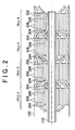
- FIG 2 is a cross-sectional view of the secondary battery 100 shown in FIG 1 cut length-wise along the shaft 110.
- the secondary battery 100 includes a plurality of cells A and B. These cells A and B are arranged alternately. In each of the cells A and B, the positive electrode sheet 202, the separator sheet 204, the negative electrode sheet 206, and the separator 208 are wound.
- the positive electrode sheet 202 and the negative electrode sheet 206 form edge portions of each cell (i.e., portions which protrude from the portion of the cell where the sheets are layered on top of one another) so that when two of the cells are connected, the positive electrode sheet 202 of one cell faces the negative electrode sheet 206 of the other cell.
- the width of the edge portions i.e., the length in the axial direction
- the positive electrode sheet 202 and the negative electrode sheet 206 are both made of electrical conductive material.
- the positive electrode sheet 202 is coated with sintered nickel, for example, and the negative electrode sheet 206 is coated with a hydrogen alloy in a paste form, for example, but the invention is not limited to this.
- the separators 204 and 208 are sheets for separating the positive electrode sheet 202 from the negative electrode sheet 206.
- these separators 204 and 208 are made of a non-woven fabric or a finely perforated film, for example, but the invention is not limited to this. Any material may be used as long as it is stable with respect to the electrolytic solution and has a saturation rate for the electrolytic solution that fulfills a predetermined condition.
- Cell B is formed after cell A.
- the edge portion of the electrode in cell B is wound around so as to overlap the edge portion of the electrode in cell A. Accordingly, the edge portion of the electrode in cell A is pressed toward the shaft 110 by the edge portion of the electrode in the adjacent cell B. This ensures the connection between cell A and cell B.
- This construction obviates the need for a collector which is necessary in a typical secondary battery. As a result, even if a plurality of cells are connected to obtain a predetermined voltage, the internal resistance from connecting the cells can be reduced. Accordingly, output from the secondary battery can be improved and the number of parts can be reduced.
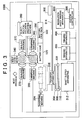
- This manufacturing system 1000 includes manufacturing equipment that carries out various manufacturing processes, from introducing the structural materials of the secondary battery (i.e., shaft, electrode sheets, separator sheets, insulation sheets, electrolytic solution, battery case, and the like) to sealing the battery case.
- structural materials of the secondary battery i.e., shaft, electrode sheets, separator sheets, insulation sheets, electrolytic solution, battery case, and the like
- the manufacturing system 1000 includes a system controller 300, a linear guide controller 302, a transfer apparatus 306, a shaft supply apparatus 312, an inserting machine 334, a battery case rack 332, a belt conveyer 340, two crimping machines 350, an electrolytic solution injecting machine 360 which is provided with a nozzle 362, two sealing machines 370, two winding apparatuses 400, and an insulation sheet winding apparatus 600.
- the linear guide controller 302 controls the operation of the transfer apparatus 306 based on a command from the system controller 300.
- the transfer apparatus 306 moves on a transfer rail 314 and rotates around to a predetermined location (illustrated by the dotted lines in FIG 3 ) to supply the shaft 110, around which the sheets have already been wound, to the inserting machine 334.
- the transfer apparatus 306 is provided with a loader 304, which in turn is provided with chucks 308.
- the loader 304 grabs the shaft 110 with the chucks 308 based on a command from the linear guide controller 302.
- the chucks 308 release the shaft 110 so as to supply it to a predetermined location.
- the chucks 308 take the shaft 110 from the shaft supply apparatus 312 and holds it until supplying it to the inserting machine 334.
- the shaft 110 is a hollow shaft such as a tube, for example, but it may also be a solid shaft.
- a coolant medium can be injected into the shaft.
- the coolant medium can be injected into the shaft at the time the secondary battery is mounted (in a vehicle, for example), for example.
- the shaft 110 may be a rigid metal body, for example, as long as it has a coating of insulation on the outside (the outside may be coated with resin, for example). This enables the inside of the shaft 110 to be insulated from the outside of the shaft 110.
- the winding apparatus 400 winds the positive electrode sheet 202, the negative electrode sheet 206, and the separators 204 and 208 on the shaft 110, as will be described later.
- the manufacturing system 1000 is provided with two of the winding apparatuses 400, but the invention is not limited to this. That is, more or fewer of the winding apparatuses 400 may be provided depending on, for example, the size of the secondary battery (i.e., the length in the axial direction) or conditions such as production rate.
- the shaft supply apparatus 312 supplies the shaft 110, which is part of the secondary battery, to the transfer apparatus 306 every predetermined cycle time according to a command from the system controller 300.
- the inserting machine 334 inserts the shaft 110, onto which the positive electrode sheet 202, the separators 204 and 208, the negative electrode sheet 206, and the insulation sheet 210 have been wound, into the battery case 120 according to a command from the system controller 300.
- the battery case 120 is supplied from the batter case rack 332 toward the wound shaft 110 according to a command from the system controller 300.
- the crimping machine crimps the battery case 120 at predetermined locations so as to join the cells ( FIG 2 ).
- the predetermined locations are at portions at which one cell is connected to another (i.e., portions at which the edge portions (offset portions) of the electrodes of each cell overlap). This ensures connection between the cells. Further, using the crimping method it is possible to reliably connect the overlapping edge portions of two adjacent cells in cases where two adjacent cells are unable to be connected by, for example, metallurgical bonding such as welding or pressing with a ring member or the like.
- the electrolytic solution injecting machine 360 supplies electrolytic solution to inside the battery case 120.
- This electrolytic solution may be, for example, diluted sulfuric acid or an aqueous potassium hydroxide, but it is not limited to this as long as the electrolytic solution has i) good ion solubility and ion conductivity, ii) no electron conductivity, and iii) a high stability temperature zone or a high break down voltage by which the solute in the electrolytic solution breaks down.
- the sealing machine 370 seals the secondary battery after the electrolytic solution has been injected so as to prevent the electrolytic solution from leaking out.
- There are various methods for sealing including, but not limited to, pressing or inserting a sealing plate or a seal.
- Assembly of the secondary battery is complete when the shaft 110 wound with the sheets and the electrolytic solution are sealed in the battery case 120 and adjacent cells are joined through predetermined processes with the manufacturing equipment described above.
- the secondary battery is then transferred on the conveyer belt 340 to the next process (such as an inspection process).
- the winding apparatus 400 includes a pressure roller 402, a hydraulic piston 406, two sheet cutters 408, two sheet holders 412, an adhesive applying portion 416, two feed rollers 404, and four sheet rollers 410, 420, 430, and 440.
- the pressure roller 402 presses the sheets onto the shaft 110 with the pressure applied by the hydraulic piston 406. Once the winding of the sheets starts, the pressure roller 402 continues to press the sheets onto the shaft 110 with regulated hydraulic pressure.
- the positive electrode sheet 202 is originally wound on the sheet roller 410; the separator sheet 204 is originally wound on the sheet roller 420; the negative electrode sheet 206 is originally wound on the sheet roller 430; and the separator sheet 208 is originally wound on the sheet roller 440.
- a predetermined amount of tension is applied to these sheets so as to prevent them from sagging.
- the sheets supplied from the sheet rollers are arranged in a predetermined location with the feed rollers 404 and supplied to the shaft 110 while passing between the sheet holders 412.
- the adhesive applying portion 416 applies an adhesive to the ends of the sheets to prevent the ends from coming away from the shaft 110.
- the end portions of the sheets are then feed to the shaft 110.
- the pressure roller 402 is pressed by the hydraulic piston 406 so as to press the sheets to the shaft 110. As a result, the ends of the sheets adhere to the shaft 110.
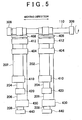
- FIG 5 is a top view of the winding apparatus 400 with the sheets arranged in the predetermined location.
- the sheets wound around the shaft 110 are wound in the following order from the inside (nearest the shaft 110) to the outside (farthest away from the shaft 110) in the radial direction of the cell: the positive electrode sheet 202, the separator sheet 204, the negative electrode sheet 206, and the separator sheet 208.
- the positive secondary battery 202 and the negative electrode sheet 206 are arranged so their edge portions are offset from one another.
- the cells A and B are thus formed by winding the sheets arranged in this way on the shaft 110, as shown in FIG 2 .
- any one edge portion of each cell is formed of sheets all having one polarity, and the other edge portion of each cell is formed of sheets all having another polarity, such that each cell A and B has both a positive pole (electrode) and a negative pole (electrode).
- This construction enables the edge portions to be used to connect adjacent cells together.
- FIG. 6 is a side view of the insulation sheet winging apparatus 600 shown in FIG. 3 .
- the insulation sheet winding apparatus 600 includes a pressure roller 602, two feed rollers 604, a hydraulic piston 606, two sheet cutters 608, a sheet roller 610, and a sheet holder 612.
- the insulation sheet 210 is originally wound on the sheet roller 610 and a predetermined amount of tension is applied to the insulation sheet 210 so that it does not sag.
- rollers The respective functions of the rollers, hydraulic piston 606, sheet cutters 608, sheet holders 612, and adhesive applying portion 616 are essentially the same as those of the rollers, the hydraulic piston 406, the sheet cutters 408, the sheet holder 412, and the adhesive applying portion 416 so they will not be repeated.
- the insulation sheet winding apparatus 600 winds the insulation sheet 210 around the outer periphery of the shaft 110 so that the positive electrode sheet 202 or the negative electrode sheet 206 wound by the winding apparatus 400 can be insulated from the outside.
- the manufacturing method of the secondary battery 100 according to the exemplary embodiment will now be described with reference to the flowchart of FIGS. 7A and 7B .
- the manufacturing method may be used, for example, in the manufacturing system 1000 shown in FIG. 3 .
- step S702 the system controller 300 initializes control data.
- This control data includes a counter p indicative of the number of windings of the sheets, the number of cells in the secondary battery, and the like.
- step S704 the shaft supply apparatus 312 supplies the shaft 110 to a predetermined location according to a command from the system controller 300.
- This predetermined location is a location from which the chucks 308 are able to grab the shaft 110. This location can be changed depending particular characteristics of the shaft, such as the length of the shaft 110 and whether the shaft is hollow or solid.
- step S706 the loader 304 sets the shaft 110 in a predetermined initial state, in which both ends of the shaft 110 are grabbed by the chucks 308 provided on the loader 304.
- step S712 the winding apparatus 400 sets the sheets against the shaft 110. Accordingly, the ends of the positive electrode sheet 202, the negative electrode sheet 206, and the separator sheets 204 and 208 adhere to the shaft 110. Pressure is then applied to the ends by the pressure roller 402 so that they do not come away from the shaft 110.
- step S718 the system controller 300 increases the counter p by 1, thus recording the completion of one winding process with respect to the shaft 110.
- step S720 the system controller 300 determines whether the counter p is equal to 1. If the determination indicates that the counter p is 1 (i.e., YES in step S720), the routine proceeds on to step S722. If the determination does not indicate that the counter p is 1 (i.e., NO in step S720), the routine proceeds on to step S724.
- step S722 the system controller 300 moves the transfer apparatus 306 a predetermined interval with the linear guide controller 302. This predetermined interval is the width of the positive electrode sheet 202 or the negative electrode sheet 206. Moving the transfer apparatus 306 in this way enables the shaft 110 to be put in position for the next winding. The routine then returns to step S710.
- step S724 the insulation sheet winding apparatus 600 winds the insulation sheet onto the shaft 110. This winding process is executed after the positive electrode sheet 202, the negative electrode sheet 206, and the separator sheets 204 and 208 have finished being wound.
- step S726 the inserting machine 334 inserts the shaft 110, around which the insulation sheet has been wound, into the battery case 120. This is done after it has been confirmed that the insulation sheet is wound around the shaft 110 so as to prevent a shaft without the insulation sheet from being inserted into the battery case 120.
- step S728 the electrolytic solution injecting machine 360 injects a predetermined amount of electrolytic solution into the battery case 120 through the nozzle 362 according to a command from the system controller 300.
- the battery case 120 is then transferred to the crimping machine 350.
- step S730 the crimping machine 350 crimps the battery case 120 in a predetermined location on the outside according to a command from the system controller 300.
- This predetermined location is preset based on the size (length in the axial direction) of the cell in the secondary battery.
- the battery case 120 is then transferred to the sealing machine 370.
- step S732 the sealing machine 370 seals an open portion of the battery case 120 according to a command from the system controller 300 so as to prevent the electrolytic solution that has been injected into the battery case 120 from leaking out.
- the control data of the system controller 300 is initialized (step S702) and the shaft 110 is supplied to a predetermined location by the shaft supply apparatus 312 (step S704).
- the chucks 308 then grab the shaft 110 according to a command from the linear guide controller 302 and set the shaft 110 in an initial state (step S706). After confirming that the chucks 308 have grabbed the shaft 110, the transfer apparatus 306 then moves to the winding apparatus 400 (step S708).
- the adhesive is applied to the ends of the positive electrode sheet 202, the negative electrode sheet 206, and the separator sheets 204 and 208 (step S710).
- the loader 304 rotates holding the shaft 110 with the chucks 308 and the sheets start to be wound with the edge portions of the positive electrode sheet 202 and the negative electrode sheet 206 offset (step S714).
- the sheets Once the sheets have been wound a predetermined number of times, they are then cut with the sheet cutters 408 and the winding process ends (step S716). The sheets are then held in a predetermined location by the sheet holders 412.
- step S718 The control data of the system controller 300 is then increased by 1 (step S718). If it is confirmed at this time that the first winding process has just been completed (i.e., YES in step S720), the linear guide controller 302 moves the transfer apparatus 306 a predetermined interval (step S722) where the adhesive is applied to the sheets so that they are set in the initial state again (step S710). The sheets are then adhered to the shaft 110 (step S712) and the winding process is performed again (step S714 and 716).
- step S718 when the counter of the system controller 300 is increased by 1 (step S718), it is determined that the second winding process has just been completed (i.e., NO in step S720), the linear guide controller 302 moves the transfer apparatus 306 to a predetermined location with respect to the insulation sheet winding apparatus 600. After the insulation sheet 210 has been wound on the sheet 110 (step S724), the transfer apparatus 306 moves to a predetermined location and rotates so that it is facing the opposite direction that it was previously facing. The chucks 308 then release the shaft 110 in a predetermined location for the inserting machine 334.
- the battery case 120 is then rotated so that an open portion thereof faces upward.
- the electrolytic solution injecting machine 360 then injects electrolytic solution into the open portion (step S728) and the battery case 120 is then transferred to the crimping machine 350.
- the crimping machine 350 then crimps the battery case 120 at a predetermined location, thus joining the cells at the connecting portion (step S730).
- the battery case 120 is transferred on a belt conveyer 340 to a predetermined location with respect to the sealing machine 370.
- the sealing machine 370 then seals the open portion of the battery case 120 (step S732), after which the battery case 120 is transferred on to the next process.
- the positive electrode sheet 202 and the negative electrode sheet 206 are wound, with the separator sheets 204 and 208 alternately interspersed in between, around the shaft 110 of the secondary battery in such a way that the edge portion of the positive electrode sheet 202 is offset from the edge portion of the negative electrode sheet 206 in the direction in which the cells connect. Accordingly, the edge portion of the positive electrode sheet 202 and the edge portion of the negative electrode sheet 206 can be used to connect adjacent cells, which obviates the need for a separate connecting member and process. As a result, internal resistance from the connection between the cells is reduced so output of the secondary battery can be improved. Therefore, it is possible to provide a secondary battery, a manufacturing system, and manufacturing method for that secondary battery that can improve output and reduce the number of parts and manufacturing processes.
- a first forming step (step S714) is performed by the winding apparatus 400 to form a cell in which the edge portion of the positive electrode sheet 202 and the edge portion of the negative electrode sheet 206 are offset in the direction in which the cells are connected.
- a second forming step (step S714 which is executed again after step S722) is also performed in the same way by the winding apparatus 400 to form another cell in which the edge portion of an electrode having a different polarity from the electrode of the cell formed in the first forming step overlaps with the edge portion of the electrode of the cell formed in the first forming step.
- step S714 After the winding of the sheets in the first forming step (step S714) is complete, the transfer apparatus holding the shaft 110 is moved (step S722) and the winding of sheets in the second forming step is performed (step S714).
- the second forming step may be performed without changing the position of the shaft 110.
- the second forming step (step S714 after step S722 is performed) can be performed by providing another winding apparatus having the same function as the winding apparatus 400 next to the location where the sheets are wound by the winding apparatus 400. This eliminates the time it takes to move the shaft 110, thereby improving efficiency in the winding process.
- FIGS. 8 to 10B A second exemplary embodiment will hereinafter be described with reference to FIGS. 8 to 10B .
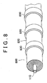
- the secondary battery 800 includes the shaft 110, positive and negative electrode sheets and separator sheets wound around the shaft 110, an insulation sheet (not shown), a battery case 820, rings 830 fit around the battery case 820 at predetermined intervals, and electrolytic solution (not shown) filled inside the battery case 820.
- the positive and negative electrode sheets, separator sheets, and insulation sheet are wound around the shaft 110 in the same manner as in the secondary battery 100 according to the first exemplary embodiment so descriptions thereof will not be repeated.
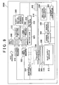
- a manufacturing system 2000 for manufacturing the secondary battery 800 according to the second exemplary embodiment will now be described with reference to FIG 9 .
- This manufacturing system 2000 differs from the manufacturing system 1000 according to the first exemplary embodiment in that it includes a ring supplying machine 950 and a ring press machine 952 instead of the crimping machine 350 ( FIG 3 ).
- the other manufacturing equipment is the same as that used in the manufacturing system 1000 so descriptions thereof will be omitted.
- the ring supplying machine 950 supplies the rings 830 to predetermined locations on the secondary battery 800 ( FIG. 8 ).
- the ring press machine 952 then presses the rings 830 from the outside toward the secondary battery 800 so as to join adjacent cells at the connecting portion.
- the rings 830 at the joining portion of the cells, it is possible to reinforce the joined state of the connecting portion of the cells. Further, even in cases where joining by crimping (at the crimping portion 130 in FIG 1 ) is not possible, the pressed rings enable internal resistance to be reduced, thereby suppressing a reduction in output voltage.
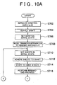
- the manufacturing method of the secondary battery 800 according to this exemplary embodiment will now be described with reference to the flowchart of FIGS. 10A and 10B .
- This manufacturing method may be used with the manufacturing system 2000 shown in FIG 9 , for example.
- the method for manufacturing the secondary battery according to this exemplary embodiment differs from the method for manufacturing the secondary battery according to the first exemplary embodiment ( FIGS. 7A and 7B ) in that after injection of electrolytic solution (step S728), a process is performed to join adjacent cells at the connecting portion using rings (step S1030).
- the other processes are the same as the those in the manufacturing method according to the first exemplary embodiment so descriptions thereof will be omitted.
- step S1030 the ring press machine 952 presses the rings 830 supplied to a predetermined location by the ring supply machine 950.
- This predetermined location is the connecting portion between adjacent cells in the secondary battery 800.
- the rings 830 are then pressed, for example, in a direction from a closed portion (not shown) of the secondary battery 800 toward an open portion (also not shown) of the secondary battery 800 at each connecting portion so as to release the stress in a secondary battery case 820 from the open portion.
- the belt conveyer 340 transfers the secondary battery 800 with the injected electrolytic solution to the ring press machine 952.
- One of the rings 830 is then supplied to the secondary battery 800 by the ring supply machine 950, and the ring press machine 952 presses the ring 830 onto the secondary battery 800 at a predetermined location so as to join the cells at the connecting portion (step S1030).
- the open portion of the battery case 820 is then sealed and the secondary battery 800 is transferred to the next process.
- a plurality of cells in the secondary battery 800 are joined at connecting portions by pressing the rings 830 provided around the outside of the cells.
- the rings 830 deform from the pressure so even after the pressure is released from the rings 830, adjacent cells are maintained in a joined state at the connecting portions. Accordingly, even in a case where the material of the battery case 120 is not suitable for plastic deformation (such as a resin film), adjacent cells can be reliably connected so internal resistance in the secondary battery 800 can be reduced.
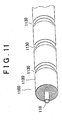
- a third exemplary embodiment will hereinafter be described with reference to FIGS. 11 to 13B .
- the secondary battery 1100 includes the shaft 110, positive and negative electrode sheets and separator sheets, and an insulation sheet (not shown), all of which are wound around the shaft 110, a battery case 1120, and electrolytic solution (not shown) filled inside the battery case 1120.
- the secondary battery 1100 is welded at weld zones 1130 spaced at predetermined intervals.
- the positive and negative electrode sheets, separator sheets, and insulation sheet are wound around the shaft 110 in the same manner as with the secondary battery 100 according to the first exemplary embodiment so descriptions thereof will not be repeated.
- a manufacturing system 3000 for manufacturing the secondary battery 1100 according to the third exemplary embodiment will now be described with reference to FIG 12 .
- This manufacturing system 3000 differs from the manufacturing system 1000 according to the first exemplary embodiment in that it includes two welding machines 1250 instead of the crimping machine 350 ( FIG 3 ).
- the other manufacturing equipment is the same as that used in the manufacturing system 1000 so descriptions thereof will be omitted.
- the welding machine 1250 welds the secondary battery 1100 in predetermined locations. Any of various welding methods may be used, including, but not limited to, ultrasonic welding and laser welding.
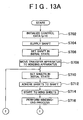
- the manufacturing method of the secondary battery 1100 according to this exemplary embodiment will now be described with reference to the flowchart of FIGS. 13A and 13B .
- This manufacturing method may be used with the manufacturing system 3000 shown in FIG. 12 , for example.
- the method for manufacturing the secondary battery according to this exemplary embodiment differs from the method for manufacturing the secondary battery according to the first exemplary embodiment ( FIGS. 7A and 7B ) in that after the injection of electrolytic solution (step S728), a process is performed to join adjacent cells at the connecting portion by welding (step S1330).
- the other processes are the same as the those in the manufacturing method according to the first exemplary embodiment so descriptions thereof will be omitted.
- step S1330 the welding machine 1250 welds the secondary battery 1100 in a predetermined location.
- This predetermined location is a portion where adjacent cells in the secondary battery 1100 are to be connected.
- the belt conveyer 340 transfers the secondary battery 1100 with the injected electrolytic solution to the welding machine 1250.
- the welding machine 1250 then welds the secondary battery 1100 at predetermined locations (step S1330), thus joining the cells at the connecting portions.
- the portions where adjacent cells in the secondary battery 1100 are to be connected are joined by welding, thus enabling a reliable connection. Accordingly, internal resistance is reduced so output from the secondary battery 1100 can be improved. Also, because there is no need for a connecting member, the process of attaching such a connecting member is also unnecessary. As a result, it is possible to provide a secondary battery, a manufacturing system, and manufacturing method for that secondary battery which can improve output and reduce the number of parts and manufacturing processes.
- the controllers are implemented with general purpose processors. It will be appreciated by those skilled in the art that the controllers can be implemented using a single special purpose integrated circuit (e.g., ASIC) having a main or central processor section for overall, system-level control, and separate sections dedicated to performing various different specific computations, functions and other processes under control of the central processor section.
- the controllers can be a plurality of separate dedicated or programmable integrated or other electronic circuits or devices (e.g., hardwired electronic or logic circuits such as discrete element circuits, or programmable logic devices such as PLDs, PLAs, PALs or the like).
- the controllers can be suitably programmed for use with a general purpose computer, e.g., a microprocessor, microcontroller or other processor device (CPU or MPU), either alone or in conjunction with one or more peripheral (e.g., integrated circuit) data and signal processing devices.
- a general purpose computer e.g., a microprocessor, microcontroller or other processor device (CPU or MPU)
- CPU or MPU processor device
- peripheral e.g., integrated circuit
- any device or assembly of devices on which a finite state machine capable of implementing the procedures described herein can be used as the controllers.
- a distributed processing architecture can be used for maximum data/signal processing capability and speed.
Landscapes
- Engineering & Computer Science (AREA)
- General Engineering & Computer Science (AREA)
- Manufacturing & Machinery (AREA)
- Chemical & Material Sciences (AREA)
- Chemical Kinetics & Catalysis (AREA)
- Electrochemistry (AREA)
- General Chemical & Material Sciences (AREA)
- Mechanical Engineering (AREA)
- Secondary Cells (AREA)
- Connection Of Batteries Or Terminals (AREA)
Claims (10)
- Sekundärbatterie mit einer Mehrzahl an Zellen, die in einer Richtung ausgerichtet sind, wobei jede Zelle aus der Mehrzahl an Zellen eine flache tafelförmige erste Elektrode mit einer Polarität (202) und eine flache tafelförmige zweite Elektrode mit einer anderen Polarität (206) aufweist, die aufeinander geschichtet sind und wobei sich ein Separator (204, 208) dazwischen befindet; und
einem wellenförmigen Element (110), um das die geschichteten Elektroden gewickelt sind, dadurch gekennzeichnet, dass:sich ein Randabschnitt der ersten Elektrode in einer ersten Zelle aus der Mehrzahl an Zellen mit einem Randabschnitt der zweiten Elektrode in einer zweiten Zelle aus der Mehrzahl an Zellen, die sich neben der ersten Zelle befindet, überlappt und verbindet, wobeidie geschichteten Elektroden so um das wellenförmige Element (110) gewickelt sind, dass der Randabschnitt der ersten Elektrode in der ersten Zelle aus der Mehrzahl an Zellen um den Randabschnitt der zweiten Elektrode in der zweiten Zelle aus der Mehrzahl an Zellen, die sich neben der ersten Zelle befindet, gewickelt ist, und wobeisich die Polarität des Randabschnitts der ersten Elektrode in der ersten Zelle von der Polarität des Randabschnitts der zweiten Elektrode in der zweiten Zelle unterscheidet, und die Mehrzahl an Zellen in einer axialen Richtung des wellenförmigen Elements (110) ausgerichtet ist. - Sekundärbatterie nach Anspruch 1, wobei die Oberfläche des wellenförmigen Elements (110) isoliert ist.
- Sekundärbatterie nach Anspruch 1, wobei die Form der ersten Elektrode (202) und die Form der zweiten Elektrode (206) gleich sind, und die erste Elektrode (202) und die zweite Elektrode (206) in der einen Richtung versetzt zueinander angeordnet sind.
- Sekundärbatterie nach Anspruch 1, wobei das wellenförmige Element (110) hohl ist.
- Sekundärbatterie nach einem der Ansprüche 1 bis 4, wobei der Randabschnitt der ersten Elektrode in der ersten Zelle und der Randabschnitt der zweiten Elektrode in der zweiten Zelle durch Einfalzen verbunden werden.
- Sekundärbatterie nach einem der Ansprüche 1 bis 4, wobei die Sekundärbatterie ferner ein Ringelement (830) aufweist und der Randabschnitt der ersten Elektrode in der ersten Zelle und der Randabschnitt der zweiten Elektrode in der zweiten Zelle durch Druck des Ringelements (830) verbunden werden.
- Sekundärbatterie nach einem der Ansprüche 1 bis 4, wobei der Randabschnitt der ersten Elektrode in der ersten Zelle und der Randabschnitt der zweiten Elektrode in der zweiten Zelle durch Schweißen verbunden werden.
- Sekundärbatterie nach einem der Ansprüche 1 bis 4, wobei die Sekundärbatterie ferner ein Gehäuse (120; 820; 1120) aufweist, das die Mehrzahl an Zellen umschließt, und der Randabschnitt der ersten Elektrode in der ersten Zelle und der Randabschnitt der zweiten Elektrode in der zweiten Zelle verbunden werden, indem sie durch Druck zusammengedrückt werden, der von außen auf das Gehäuse (120; 820; 1120) ausgeübt wird.
- Sekundärbatterie nach Anspruch 1, wobei die Mehrzahl an Zellen erste und zweite Zellen (A, B) beinhaltet, die in einer axialen Richtung des wellenförmigen Elements (110) ausgerichtet sind, wobei jede Zelle aufweist:eine erste im Wesentlichen zylindrische Elektrode, die durch die flache tafelförmige erste Elektrodenschicht (202), die um das wellenförmige Element (110) gewickelt ist, ausgebildet wird, und die die erste Polarität aufweist; und eine zweite im Wesentlichen zylindrische Elektrode, die durch die flache tafelförmige zweite Elektrodenschicht (206), die um das wellenförmige Element (110) gewickelt ist, ausgebildet wird, und die die zweite Polarität aufweist;wobei der Randabschnitt der ersten im Wesentlichen zylindrischen Elektrode der ersten Polarität in der ersten Zelle (A) von einem ersten Ende der ersten Zelle (A) aus verläuft und in einer ersten Richtung gebogen ist, und der Randabschnitt der zweiten im Wesentlichen zylindrischen Elektrode der zweiten Polarität in der zweiten Zelle (B) von einem zweiten Ende der zweiten Zelle (B) neben der ersten Zelle (A) aus verläuft und in einer zweiten Richtung entgegengesetzt zu der ersten Richtung gebogen ist, so dass sich die Randabschnitte der ersten und zweiten im Wesentlichen zylindrischen Elektroden überlappen und miteinander elektrisch verbunden sind.
- Sekundärbatterie nach Anspruch 1, wobei die Mehrzahl an Zellen erste und zweite Zellen (A, B) beinhaltet, die in einer axialen Richtung des wellenförmigen Elements (110) ausgerichtet sind, wobei jede Zelle aufweist:eine erste im Wesentlichen zylindrische Elektrode, die durch die flache tafelförmige erste Elektrodenschicht (202), die um das wellenförmige Element (110) gewickelt ist, ausgebildet wird, und die die erste Polarität aufweist;eine zweite im Wesentlichen zylindrische Elektrode, die durch die flache tafelförmige erste Elektrodenschicht (202), die um das wellenförmige Element (110) gewickelt ist, ausgebildet wird, und die die erste Polarität aufweist;eine dritte im Wesentlichen zylindrische Elektrode, die durch die flache tafelförmige zweite Elektrodenschicht (206), die um das wellenförmige Element (110) gewickelt ist, ausgebildet wird, und die die zweite Polarität aufweist;eine vierte im Wesentlichen zylindrische Elektrode, die durch die flache tafelförmige zweite Elektrodenschicht (206), die um das wellenförmige Element (110) gewickelt ist, ausgebildet wird, und die die zweite Polarität aufweist;wobei sich eine Mehrzahl an Separatoren (204, 208) zwischen den im Wesentlichen zylindrischen Elektroden befindet, um die erste, zweite, dritte und vierte im Wesentlichen zylindrische Elektrode jeweils voneinander zu trennen; undwobei der Randabschnitt zumindest einer im Wesentlichen zylindrischen Elektrode der ersten Polarität in der ersten Zelle (A) von einem Ende der ersten Zelle (A) aus verläuft und in einer ersten Richtung gebogen ist und der Randabschnitt zumindest einer im Wesentlichen zylindrischen Elektrode der zweiten Polarität in der zweiten Zelle (B) von einem angrenzenden Ende der zweiten Zelle (B) aus verläuft und in einer zweiten Richtung entgegengesetzt zu der ersten Richtung gebogen ist, so dass sich die Randabschnitte der ersten und zweiten im Wesentlichen zylindrischen Elektroden überlappen und miteinander elektrisch verbunden sind.
Applications Claiming Priority (2)
| Application Number | Priority Date | Filing Date | Title |
|---|---|---|---|
| JP2003035272A JP4461686B2 (ja) | 2003-02-13 | 2003-02-13 | 二次電池、その製造装置および製造方法 |
| JP2003035272 | 2003-02-13 |
Publications (3)
| Publication Number | Publication Date |
|---|---|
| EP1489679A2 EP1489679A2 (de) | 2004-12-22 |
| EP1489679A3 EP1489679A3 (de) | 2005-05-11 |
| EP1489679B1 true EP1489679B1 (de) | 2014-03-26 |
Family
ID=32844391
Family Applications (1)
| Application Number | Title | Priority Date | Filing Date |
|---|---|---|---|
| EP04002241.0A Expired - Lifetime EP1489679B1 (de) | 2003-02-13 | 2004-02-02 | Sekundärbatterie |
Country Status (5)
| Country | Link |
|---|---|
| US (1) | US20040161663A1 (de) |
| EP (1) | EP1489679B1 (de) |
| JP (1) | JP4461686B2 (de) |
| KR (1) | KR100586472B1 (de) |
| CN (1) | CN1277328C (de) |
Families Citing this family (11)
| Publication number | Priority date | Publication date | Assignee | Title |
|---|---|---|---|---|
| JP4293247B2 (ja) * | 2007-02-19 | 2009-07-08 | ソニー株式会社 | 積層型非水電解質電池およびその製造方法 |
| KR100953890B1 (ko) * | 2007-10-12 | 2010-04-22 | 킴스테크날리지 주식회사 | 쿼지바이폴라 구조를 갖는 전기화학셀 |
| KR100983047B1 (ko) * | 2008-07-01 | 2010-09-17 | 킴스테크날리지 주식회사 | 보조전극을 갖는 쿼지 바이폴라 전기화학셀 |
| JP4775668B2 (ja) * | 2008-08-28 | 2011-09-21 | トヨタ自動車株式会社 | 捲回電極体の製造方法およびその装置、および、電池の製造方法 |
| CN102576849B (zh) * | 2009-09-28 | 2015-01-14 | 丰田自动车株式会社 | 电池的制造方法 |
| DE102011105040A1 (de) * | 2011-05-06 | 2012-11-08 | Klaus Ebert | Lithiumsenkundärzellenanordnung |
| JP5838073B2 (ja) * | 2011-11-04 | 2015-12-24 | 株式会社日立製作所 | 円筒捲回型電池 |
| KR101809142B1 (ko) | 2015-05-12 | 2017-12-14 | 주식회사 엘지화학 | 상호 연결된 전극을 포함하는 전극조립체 |
| KR101769687B1 (ko) * | 2015-12-09 | 2017-08-21 | 숭실대학교산학협력단 | 연속형 전기전자 소자 및 그 제조 방법 |
| IT202000026593A1 (it) * | 2020-11-06 | 2022-05-06 | Ferrari Spa | Metodo di assemblaggio celle, unita' di accumulo e relativo pacco batteria veicolare |
| CN115911763A (zh) * | 2022-12-16 | 2023-04-04 | 天津动力电池再生技术有限公司 | 一种快速拆装的动力电池 |
Family Cites Families (19)
| Publication number | Priority date | Publication date | Assignee | Title |
|---|---|---|---|---|
| GB1096686A (en) * | 1964-10-27 | 1967-12-29 | Oldham & Son Ltd | Improvements in or relating to multi-cell electric storage batteries |
| US4119772A (en) * | 1974-10-31 | 1978-10-10 | Chloride Group Limited | Lead acid cells and batteries |
| IL57109A (en) * | 1979-04-22 | 1982-04-30 | Yeda Res & Dev | System of electrochemical cells |
| US4521498A (en) * | 1982-07-22 | 1985-06-04 | Gates Energy Products, Inc. | Through-the-partition intercell connection and method |
| US4583286A (en) * | 1983-03-28 | 1986-04-22 | Gnb Batteries Inc. | Apparatus and method for processing and transferring battery cell elements |
| FI77747C (fi) * | 1986-03-25 | 1989-04-10 | Neste Oy | Foerfarande och anordning foer framstaellning av skivsystem foer en ackumulator. |
| US5106708A (en) * | 1990-09-12 | 1992-04-21 | General Motors Corporation | Bipolar battery and assembly method |
| JPH06349460A (ja) * | 1993-04-15 | 1994-12-22 | Sony Corp | 電 池 |
| US5370711A (en) * | 1993-07-21 | 1994-12-06 | Ev Energy Systems, Inc. | Method for making an electrical energy storage device |
| JPH09231993A (ja) * | 1996-02-22 | 1997-09-05 | Toyota Motor Corp | 円筒型電池 |
| US6379840B2 (en) * | 1998-03-18 | 2002-04-30 | Ngk Insulators, Ltd. | Lithium secondary battery |
| US6287719B1 (en) * | 1998-06-15 | 2001-09-11 | Eveready Battery Company, Inc. | Battery including a non-aqueous multi-cell spiral-wound electrode assembly |
| JP3419311B2 (ja) * | 1998-07-15 | 2003-06-23 | トヨタ自動車株式会社 | バイポーラ型リチウムイオン2次電池 |
| DE19857638A1 (de) * | 1998-12-14 | 2000-06-15 | Varta Geraetebatterie Gmbh | Elektrischer Akkumulator in Form einer Knopfzelle |
| DE10064648C2 (de) * | 1999-12-28 | 2003-09-18 | Honda Motor Co Ltd | Batterieeinheit |
| JP3608047B2 (ja) * | 2001-01-23 | 2005-01-05 | トヨタ自動車株式会社 | バイポーラ型二次電池の製造方法およびバイポーラ型二次電池 |
| JP3736746B2 (ja) * | 2001-06-04 | 2006-01-18 | ソニー株式会社 | 光充電式二次電池 |
| JP4428905B2 (ja) * | 2002-02-01 | 2010-03-10 | 日本電気株式会社 | 扁平型電池およびそれを用いた組電池 |
| US6923837B2 (en) * | 2002-02-26 | 2005-08-02 | Lithium Power Technologies, Inc. | Consecutively wound or stacked battery cells |
-
2003
- 2003-02-13 JP JP2003035272A patent/JP4461686B2/ja not_active Expired - Fee Related
-
2004
- 2004-01-23 US US10/762,525 patent/US20040161663A1/en not_active Abandoned
- 2004-02-02 EP EP04002241.0A patent/EP1489679B1/de not_active Expired - Lifetime
- 2004-02-11 CN CNB200410039295XA patent/CN1277328C/zh not_active Expired - Fee Related
- 2004-02-12 KR KR1020040009220A patent/KR100586472B1/ko not_active Expired - Fee Related
Also Published As
| Publication number | Publication date |
|---|---|
| CN1277328C (zh) | 2006-09-27 |
| EP1489679A3 (de) | 2005-05-11 |
| KR20040073374A (ko) | 2004-08-19 |
| CN1521880A (zh) | 2004-08-18 |
| JP4461686B2 (ja) | 2010-05-12 |
| US20040161663A1 (en) | 2004-08-19 |
| EP1489679A2 (de) | 2004-12-22 |
| KR100586472B1 (ko) | 2006-06-07 |
| JP2004247153A (ja) | 2004-09-02 |
Similar Documents
| Publication | Publication Date | Title |
|---|---|---|
| US20230369734A1 (en) | Battery cell, battery, and electric apparatus | |
| US11923564B2 (en) | Method for producing battery module | |
| US8252457B2 (en) | Battery cell and power supply | |
| US20140186671A1 (en) | Secondary cell | |
| EP3550635B1 (de) | Batteriemodul und batteriepack damit | |
| US11031650B2 (en) | Battery module and battery pack comprising same | |
| JP2020513148A (ja) | 電極タブの溶接特性を改善した電極及びこれを含む二次電池 | |
| US9095924B2 (en) | Welded construction and resistance welding method | |
| EP1489679B1 (de) | Sekundärbatterie | |
| EP4080644B1 (de) | Elektrodenanordnung mit einer schicht zur verhinderung von verbindungsabbrüchenund verfahren zu deren herstellung | |
| CN102195080A (zh) | 锂离子二次电池 | |
| CN119404367A (zh) | 电池单体、电池和用电装置 | |
| JP3221324B2 (ja) | 薄型電池およびその製造法 | |
| KR20220092101A (ko) | 이차전지 및 이의 제조 방법 | |
| JP3829080B2 (ja) | 角形電池およびこれの電極群の製造方法 | |
| JP2022554115A (ja) | 電極リードの製造方法及び加圧機 | |
| JP3594481B2 (ja) | 密閉型電池及びその製造方法 | |
| CN111653812A (zh) | 一种可模块化的新型钒电池电堆 | |
| CN115579590B (zh) | 电芯、电池模组及电芯的制作方法 | |
| EP4712252A1 (de) | Elektrodenanordnung und verfahren zur herstellung einer sekundärbatterie mit der elektrodenanordnung | |
| US20240088448A1 (en) | Method of manufacturing battery | |
| EP4712220A2 (de) | Beutelartige sekundärbatterien, pressvorrichtungen dafür und herstellungsverfahren dafür | |
| CN121769452A (zh) | 电池及电池装置 | |
| CN121790697A (zh) | 电池装置及用电设备 | |
| CN117317529A (zh) | 一种电芯与集流体的连接方法以及电池的制备方法 |
Legal Events
| Date | Code | Title | Description |
|---|---|---|---|
| PUAI | Public reference made under article 153(3) epc to a published international application that has entered the european phase |
Free format text: ORIGINAL CODE: 0009012 |
|
| 17P | Request for examination filed |
Effective date: 20040202 |
|
| AK | Designated contracting states |
Kind code of ref document: A2 Designated state(s): AT BE BG CH CY CZ DE DK EE ES FI FR GB GR HU IE IT LI LU MC NL PT RO SE SI SK TR |
|
| AX | Request for extension of the european patent |
Extension state: AL LT LV MK |
|
| PUAL | Search report despatched |
Free format text: ORIGINAL CODE: 0009013 |
|
| RTI1 | Title (correction) |
Free format text: SEKUNDAERBATTERIE, VERFAHREN UND SYSTEM ZU IHRER HERSTELLUNG |
|
| AK | Designated contracting states |
Kind code of ref document: A3 Designated state(s): AT BE BG CH CY CZ DE DK EE ES FI FR GB GR HU IE IT LI LU MC NL PT RO SE SI SK TR |
|
| AX | Request for extension of the european patent |
Extension state: AL LT LV MK |
|
| 17Q | First examination report despatched |
Effective date: 20050705 |
|
| AKX | Designation fees paid |
Designated state(s): DE FR |
|
| 17Q | First examination report despatched |
Effective date: 20050705 |
|
| RAP1 | Party data changed (applicant data changed or rights of an application transferred) |
Owner name: TOYOTA JIDOSHA KABUSHIKI KAISHA |
|
| GRAP | Despatch of communication of intention to grant a patent |
Free format text: ORIGINAL CODE: EPIDOSNIGR1 |
|
| INTG | Intention to grant announced |
Effective date: 20131004 |
|
| GRAS | Grant fee paid |
Free format text: ORIGINAL CODE: EPIDOSNIGR3 |
|
| GRAA | (expected) grant |
Free format text: ORIGINAL CODE: 0009210 |
|
| RIN1 | Information on inventor provided before grant (corrected) |
Inventor name: NISHIDE, YUKIMASA |
|
| AK | Designated contracting states |
Kind code of ref document: B1 Designated state(s): DE FR |
|
| REG | Reference to a national code |
Ref country code: DE Ref legal event code: R096 Ref document number: 602004044662 Country of ref document: DE Effective date: 20140508 |
|
| RIN2 | Information on inventor provided after grant (corrected) |
Inventor name: NISHIDE, YUKIMASA |
|
| REG | Reference to a national code |
Ref country code: DE Ref legal event code: R084 Ref document number: 602004044662 Country of ref document: DE |
|
| REG | Reference to a national code |
Ref country code: DE Ref legal event code: R084 Ref document number: 602004044662 Country of ref document: DE Effective date: 20141117 |
|
| REG | Reference to a national code |
Ref country code: DE Ref legal event code: R097 Ref document number: 602004044662 Country of ref document: DE |
|
| PLBE | No opposition filed within time limit |
Free format text: ORIGINAL CODE: 0009261 |
|
| STAA | Information on the status of an ep patent application or granted ep patent |
Free format text: STATUS: NO OPPOSITION FILED WITHIN TIME LIMIT |
|
| 26N | No opposition filed |
Effective date: 20150106 |
|
| REG | Reference to a national code |
Ref country code: DE Ref legal event code: R097 Ref document number: 602004044662 Country of ref document: DE Effective date: 20150106 |
|
| PGFP | Annual fee paid to national office [announced via postgrant information from national office to epo] |
Ref country code: DE Payment date: 20150127 Year of fee payment: 12 |
|
| REG | Reference to a national code |
Ref country code: FR Ref legal event code: ST Effective date: 20151030 |
|
| PG25 | Lapsed in a contracting state [announced via postgrant information from national office to epo] |
Ref country code: FR Free format text: LAPSE BECAUSE OF NON-PAYMENT OF DUE FEES Effective date: 20150302 |
|
| REG | Reference to a national code |
Ref country code: DE Ref legal event code: R119 Ref document number: 602004044662 Country of ref document: DE |
|
| PG25 | Lapsed in a contracting state [announced via postgrant information from national office to epo] |
Ref country code: DE Free format text: LAPSE BECAUSE OF NON-PAYMENT OF DUE FEES Effective date: 20160901 |