EP1488974A2 - Système de régulation de la tenue de route d'un véhicule avec procédé pour éstimer la stabilité de conduite - Google Patents
Système de régulation de la tenue de route d'un véhicule avec procédé pour éstimer la stabilité de conduite Download PDFInfo
- Publication number
- EP1488974A2 EP1488974A2 EP04014405A EP04014405A EP1488974A2 EP 1488974 A2 EP1488974 A2 EP 1488974A2 EP 04014405 A EP04014405 A EP 04014405A EP 04014405 A EP04014405 A EP 04014405A EP 1488974 A2 EP1488974 A2 EP 1488974A2
- Authority
- EP
- European Patent Office
- Prior art keywords
- vehicle
- driving condition
- axle assembly
- power
- unstable
- Prior art date
- Legal status (The legal status is an assumption and is not a legal conclusion. Google has not performed a legal analysis and makes no representation as to the accuracy of the status listed.)
- Granted
Links
Images


Classifications
-
- B—PERFORMING OPERATIONS; TRANSPORTING
- B60—VEHICLES IN GENERAL
- B60K—ARRANGEMENT OR MOUNTING OF PROPULSION UNITS OR OF TRANSMISSIONS IN VEHICLES; ARRANGEMENT OR MOUNTING OF PLURAL DIVERSE PRIME-MOVERS IN VEHICLES; AUXILIARY DRIVES FOR VEHICLES; INSTRUMENTATION OR DASHBOARDS FOR VEHICLES; ARRANGEMENTS IN CONNECTION WITH COOLING, AIR INTAKE, GAS EXHAUST OR FUEL SUPPLY OF PROPULSION UNITS IN VEHICLES
- B60K28/00—Safety devices for propulsion-unit control, specially adapted for, or arranged in, vehicles, e.g. preventing fuel supply or ignition in the event of potentially dangerous conditions
- B60K28/10—Safety devices for propulsion-unit control, specially adapted for, or arranged in, vehicles, e.g. preventing fuel supply or ignition in the event of potentially dangerous conditions responsive to conditions relating to the vehicle
- B60K28/16—Safety devices for propulsion-unit control, specially adapted for, or arranged in, vehicles, e.g. preventing fuel supply or ignition in the event of potentially dangerous conditions responsive to conditions relating to the vehicle responsive to, or preventing, skidding of wheels
- B60K28/165—Safety devices for propulsion-unit control, specially adapted for, or arranged in, vehicles, e.g. preventing fuel supply or ignition in the event of potentially dangerous conditions responsive to conditions relating to the vehicle responsive to, or preventing, skidding of wheels acting on elements of the vehicle drive train other than the propulsion unit and brakes, e.g. transmission, clutch, differential
-
- B—PERFORMING OPERATIONS; TRANSPORTING
- B60—VEHICLES IN GENERAL
- B60K—ARRANGEMENT OR MOUNTING OF PROPULSION UNITS OR OF TRANSMISSIONS IN VEHICLES; ARRANGEMENT OR MOUNTING OF PLURAL DIVERSE PRIME-MOVERS IN VEHICLES; AUXILIARY DRIVES FOR VEHICLES; INSTRUMENTATION OR DASHBOARDS FOR VEHICLES; ARRANGEMENTS IN CONNECTION WITH COOLING, AIR INTAKE, GAS EXHAUST OR FUEL SUPPLY OF PROPULSION UNITS IN VEHICLES
- B60K28/00—Safety devices for propulsion-unit control, specially adapted for, or arranged in, vehicles, e.g. preventing fuel supply or ignition in the event of potentially dangerous conditions
- B60K28/10—Safety devices for propulsion-unit control, specially adapted for, or arranged in, vehicles, e.g. preventing fuel supply or ignition in the event of potentially dangerous conditions responsive to conditions relating to the vehicle
- B60K28/16—Safety devices for propulsion-unit control, specially adapted for, or arranged in, vehicles, e.g. preventing fuel supply or ignition in the event of potentially dangerous conditions responsive to conditions relating to the vehicle responsive to, or preventing, skidding of wheels
-
- B—PERFORMING OPERATIONS; TRANSPORTING
- B60—VEHICLES IN GENERAL
- B60T—VEHICLE BRAKE CONTROL SYSTEMS OR PARTS THEREOF; BRAKE CONTROL SYSTEMS OR PARTS THEREOF, IN GENERAL; ARRANGEMENT OF BRAKING ELEMENTS ON VEHICLES IN GENERAL; PORTABLE DEVICES FOR PREVENTING UNWANTED MOVEMENT OF VEHICLES; VEHICLE MODIFICATIONS TO FACILITATE COOLING OF BRAKES
- B60T8/00—Arrangements for adjusting wheel-braking force to meet varying vehicular or ground-surface conditions, e.g. limiting or varying distribution of braking force
- B60T8/17—Using electrical or electronic regulation means to control braking
- B60T8/1755—Brake regulation specially adapted to control the stability of the vehicle, e.g. taking into account yaw rate or transverse acceleration in a curve
-
- B—PERFORMING OPERATIONS; TRANSPORTING
- B60—VEHICLES IN GENERAL
- B60T—VEHICLE BRAKE CONTROL SYSTEMS OR PARTS THEREOF; BRAKE CONTROL SYSTEMS OR PARTS THEREOF, IN GENERAL; ARRANGEMENT OF BRAKING ELEMENTS ON VEHICLES IN GENERAL; PORTABLE DEVICES FOR PREVENTING UNWANTED MOVEMENT OF VEHICLES; VEHICLE MODIFICATIONS TO FACILITATE COOLING OF BRAKES
- B60T8/00—Arrangements for adjusting wheel-braking force to meet varying vehicular or ground-surface conditions, e.g. limiting or varying distribution of braking force
- B60T8/17—Using electrical or electronic regulation means to control braking
- B60T8/176—Brake regulation specially adapted to prevent excessive wheel slip during vehicle deceleration, e.g. ABS
- B60T8/1766—Proportioning of brake forces according to vehicle axle loads, e.g. front to rear of vehicle
-
- B—PERFORMING OPERATIONS; TRANSPORTING
- B60—VEHICLES IN GENERAL
- B60W—CONJOINT CONTROL OF VEHICLE SUB-UNITS OF DIFFERENT TYPE OR DIFFERENT FUNCTION; CONTROL SYSTEMS SPECIALLY ADAPTED FOR HYBRID VEHICLES; ROAD VEHICLE DRIVE CONTROL SYSTEMS FOR PURPOSES NOT RELATED TO THE CONTROL OF A PARTICULAR SUB-UNIT
- B60W10/00—Conjoint control of vehicle sub-units of different type or different function
- B60W10/04—Conjoint control of vehicle sub-units of different type or different function including control of propulsion units
- B60W10/06—Conjoint control of vehicle sub-units of different type or different function including control of propulsion units including control of combustion engines
-
- B—PERFORMING OPERATIONS; TRANSPORTING
- B60—VEHICLES IN GENERAL
- B60W—CONJOINT CONTROL OF VEHICLE SUB-UNITS OF DIFFERENT TYPE OR DIFFERENT FUNCTION; CONTROL SYSTEMS SPECIALLY ADAPTED FOR HYBRID VEHICLES; ROAD VEHICLE DRIVE CONTROL SYSTEMS FOR PURPOSES NOT RELATED TO THE CONTROL OF A PARTICULAR SUB-UNIT
- B60W10/00—Conjoint control of vehicle sub-units of different type or different function
- B60W10/10—Conjoint control of vehicle sub-units of different type or different function including control of change-speed gearings
-
- B—PERFORMING OPERATIONS; TRANSPORTING
- B60—VEHICLES IN GENERAL
- B60W—CONJOINT CONTROL OF VEHICLE SUB-UNITS OF DIFFERENT TYPE OR DIFFERENT FUNCTION; CONTROL SYSTEMS SPECIALLY ADAPTED FOR HYBRID VEHICLES; ROAD VEHICLE DRIVE CONTROL SYSTEMS FOR PURPOSES NOT RELATED TO THE CONTROL OF A PARTICULAR SUB-UNIT
- B60W10/00—Conjoint control of vehicle sub-units of different type or different function
- B60W10/18—Conjoint control of vehicle sub-units of different type or different function including control of braking systems
- B60W10/184—Conjoint control of vehicle sub-units of different type or different function including control of braking systems with wheel brakes
-
- B—PERFORMING OPERATIONS; TRANSPORTING
- B60—VEHICLES IN GENERAL
- B60W—CONJOINT CONTROL OF VEHICLE SUB-UNITS OF DIFFERENT TYPE OR DIFFERENT FUNCTION; CONTROL SYSTEMS SPECIALLY ADAPTED FOR HYBRID VEHICLES; ROAD VEHICLE DRIVE CONTROL SYSTEMS FOR PURPOSES NOT RELATED TO THE CONTROL OF A PARTICULAR SUB-UNIT
- B60W2520/00—Input parameters relating to overall vehicle dynamics
- B60W2520/26—Wheel slip
- B60W2520/263—Slip values between front and rear axle
-
- B—PERFORMING OPERATIONS; TRANSPORTING
- B60—VEHICLES IN GENERAL
- B60W—CONJOINT CONTROL OF VEHICLE SUB-UNITS OF DIFFERENT TYPE OR DIFFERENT FUNCTION; CONTROL SYSTEMS SPECIALLY ADAPTED FOR HYBRID VEHICLES; ROAD VEHICLE DRIVE CONTROL SYSTEMS FOR PURPOSES NOT RELATED TO THE CONTROL OF A PARTICULAR SUB-UNIT
- B60W2520/00—Input parameters relating to overall vehicle dynamics
- B60W2520/28—Wheel speed
Definitions
- the present invention relates to a driving condition control method and system installed in a vehicle, which are capable of controlling the driving conditions of the vehicle.
- the driving condition control system disclosed in the former publication when the vehicle runs over a road surface and a yaw sensor attached to the front portion of the vehicle body senses large amount of yaw moment, determines that the vehicle is experiencing understeer.
- the understeer means that a condition where the front of the vehicle tends to break out and slide toward the outside of an intended turn.
- the driving condition control apparatus determines that the vehicle is experiencing oversteer.
- the oversteer means that a condition in comering when the rear wheels of a vehicle tend to break loose and slide outward so that the front turns the inside of an intended turn.
- the driving condition control apparatus performs a front-rear torque distribution control for restraining the oversteer or the understeer, and/or performs a steering control for avoiding the oversteer or the understeer.
- the driving condition control apparatus disclosed in the later publication is equipped with a variable torque transmission.
- the variable torque transmission distributes torque between the right and left wheels on at least one of the axel to be satisfied with the driver's steering angle, the running speed of the vehicle, and so on.
- the apparatus disclosed in the former publication controls the driving conditions of the vehicle according to the amount of yaw moment. It is noted that the yaw moment indicates angular motion of the vehicle body about vertical axis through its center of gravity. The angular motion of the vehicle body is caused after the driving torque produced by the engine is transmitted to the wheels so that the tires are subjected to traction force from the road surface.
- the apparatus disclosed in the former publication only carries out the driving condition control after the yaw moment of the vehicle body is produced, which may delay the detection of the vehicle's driving conditions.
- the apparatus disclosed in the later publication only performs the torque distribution so that it is difficult to rapidly detect that the vehicle's driving conditions are different from driver's intended driving conditions.
- the present invention is made on the background.
- a driving condition control system is installed in a vehicle.
- the vehicle has a source of power for generating power, a first rotatable axle assembly to which a front wheel is attached, and a second rotatable axle assembly to which a rear wheel is attached, said power being transferred to the second rotatable axle assembly so that the second rotatable axle assembly is rotated.
- the driving condition control system comprises a sensing unit configured to sense a first physical quantity indicative of a rotation of the first rotatable axle assembly and a second physical quantity indicative of a rotation of the second rotatable axle assembly.
- the driving condition control system also comprises a determining unit configured to compare the first and second physical quantities of the rotations of the first and second rotational axle assemblies and to determine whether a driving condition of the vehicle is unstable according to the compared result.
- a program product having a computer-readable medium of an electronic control unit.
- the computer-readable medium stores therein a program.
- the electronic control unit is installed in a vehicle.
- the vehicle has a source of power for generating power, a first rotatable axle assembly to which a front wheel is attached, and a second rotatable axle assembly to which a rear wheel is attached.
- the power is transferred to the second rotatable axle assembly as torque so that the second rotatable axle assembly is rotated.
- the vehicle also has a sensing unit that senses a first physical quantity indicative of a rotation of the first rotatable axle assembly and a second physical quantity indicative of a rotation of the second rotatable axle assembly.
- the program causes a electronic control unit to receive the first physical quantity indicative of the rotation of the first rotatable axle assembly and the second physical quantity indicative of the rotation of the second rotatable axle assembly from the sensing unit.
- the program causes a electronic control unit to compare the first and second physical quantities of the rotations of the first and second rotational axle assemblies.
- the program causes a electronic control unit to determine whether a driving condition of the vehicle is unstable according to the compared result.
- the program causes a electronic control unit to, when the determining unit determines that the vehicle becomes one of the first and second unstable conditions, adjust the torque transferred to the second axle assembly.
- a method of controlling a driving condition of a vehicle has a source of power for generating power, a first rotatable axle assembly to which a front wheel is attached, and a second rotatable axle assembly to which a rear wheel is attached.
- the power is transferred to the second rotatable axle assembly so that the second rotatable axle assembly is rotated.
- the method comprises sensing a first physical quantity indicative of a rotation of the first rotatable axle assembly and a second physical quantity indicative of a rotation of the second rotatable axle assembly.
- the method also comprises comparing the first and second physical quantities of the rotations of the first and second rotational axle assemblies to determine whether a driving condition of the vehicle is unstable according to the compared result.
- Fig. 1 is a schematic structural view of a driving condition control system according to a first embodiment of the present invention.
- the driving condition control system CS is installed in a vehicle, such as four-wheel automobile, V that is a type of front-engine-rear-drive vehicles.
- the vehicle V is provided with an engine 5, a drive shaft 20, and an automatic transmission (AT) 7 having a gear box and mechanically connected between the engine 5 and one end of the drive shaft 20.
- the AT 7 changes the gear ratios of the gear box independently of the driver to convert the engine's power output to torque based on the gear ratios, thereby transferring the torque to the drive shaft 20.
- the vehicle V is also provided with a front axle assembly (rolling axle assembly) 11a and a rear axle assembly (drive axle assembly) 11b.
- the front axle assembly 11a has a supporting member, a right-front axle 11a1, and a left-front axle 11a2 that are individually rotatably supported therewith.
- Front left and right wheels FL and FR are fixed to the right-front axle 11a1 and the left-front axle 11a2, respectively.
- the rear axle assembly 11b has a center differential 21 with right-rear axle assembly 11b1 and left-rear axle 11b2 (half shafts) coupling right and left rear wheels RR and RL to the differential 21, respectively.
- the differential 21 is mechanically coupled to the other end of the drive shaft 20.
- the left-rear axle 11b2 is supported at its one end with the differential 21 to be rotatable around its axial direction orthogonal to the axial direction of the drive shaft 20.
- the right-rear axle 11 is supported at its one end with the differential 21 to be rotatable around its axial direction orthogonal to the drive shaft's axial direction.
- the differential 21 converts the rotation of the drive shaft DF to each rotation of each of the right and left rear wheels (right and left rear axles 11b1 and 11b2), and allows the right and left rear wheels RR and Rl to revolve at different speeds during turns.
- drum brakes (not shown) are attached, respectively.
- Each of the drum brakes has a drum attached to each of the wheels and rotatable together therewith.
- Each of the drum brakes has brake shoes fit inside thereof.
- the vehicle V has a steering wheel 12 that the driver can operate and a steering mechanism 25 mechanically connected to the steering wheel 12 and the front right and left wheels FR and FF.
- the driver's steering operation of the steering wheel 12 allows the front right and left wheels FR and FL to steer, thereby turning (steering) the vehicle V.
- the driving condition control system CS is equipped with a plurality of sensors 1a-1d, 2, and 3, a manager ECU (Electronic Control Unit) 4, an engine ECU 6, a transmission ECU 8, brake ECU 9, and braking force generating units 10a-10d.
- a manager ECU Electronic Control Unit 4
- an engine ECU 6 a transmission ECU 8
- brake ECU 9 a brake ECU 9
- braking force generating units 10a-10d is equipped with a plurality of sensors 1a-1d, 2, and 3, a manager ECU (Electronic Control Unit) 4, an engine ECU 6, a transmission ECU 8, brake ECU 9, and braking force generating units 10a-10d.
- the sensors include wheel speed sensors 1a-1d, an engine revolution sensor 2, and an intake air mass sensor 3.
- the wheel speed sensors 1a, 1b, 1c, and 1d are disposed close to the wheels FR, FL, RR, and RL, respectively.
- the wheel speed sensors 1a-1d are electrically connected to, for example, each of the ECUs 4, 6, 8, and 9.
- the wheel speed sensors 1a-1d sense the wheel speeds of the wheels FR-RL to output the sensed wheel speeds as wheel speed signals of the wheels FR-FL to the brake ECU 9.
- Each of the wheel speed signals can be used for calculating the wheel speed of each of the wheels FR-RL, the speed Vso of the vehicle body, the slip ratio indicative of how much slipping is occurring between the wheels FR-RL and the road surface, and the like.
- each of the wheel speed signals can be used for calculating rotational state of each of the front and rear axle assemblies 11a and 11b to which the wheels are attached. That is, the wheel speed signals allow physical quantity indicative of the rotation of each of the front and rear axle assemblies 11a and 11b.
- the rotational speeds Vd and Vr of the driving axle assembly (rear axle assembly) 11b and the front axle assembly 11a are used.
- the revolutions of the rear axle assembly 11b and the front axle assembly 11a may be used.
- the engine revolution sensor 2 is electrically connected to the engine ECU 6 and operative to output an engine revolution signal indicative of the revolution of the engine 5 that is served as power source for generating power (torque), thereby outputting the engine revolution signal to the engine ECU 6.
- the intake air mass sensor 3 senses intake air mass of the engine 5 to output the sensed intake air mass as intake air mass signal to the engine ECU 6.
- the driving condition control system CS includes the engine revolution sensor 2 and the intake air mass sensor 3, but they can be omitted from the structure of the system CS.
- the engine revolution and the intake air mass can be estimated according to an engine control signal outputted from the engine ECU 6.
- the manager ECU 4 receives the engine control signal outputted from the engine ECU 6 and a transmission control signal outputted from the transmission ECU 8.
- the manager ECU 4 also receives a brake control signal outputted from the brake ECU 9 and the wheel speed signals outputted from the wheel speed sensors 1a-1d.
- the manager ECU 4 performs various operations including any one of an engine control operation, a brake control operation, and a transmission control operation, for controlling the driving conditions of the vehicle V according to the received signals.
- the manager ECU 4 outputs at least one control signal based on the operation result. At least one of the engine ECU 6, the brake ECU 9, and the transmission ECU 8 receives the at least one control signal to perform at least one of the control operations corresponding to the at least one control signal.
- the engine ECU 6, which corresponds to, for example, a power control unit, is operative to control the power of the engine 5 according to the position of an accelerator pedal 30 that is operated by the drier and sensed by an accelerator pedal sensor 31.
- the accelerator pedal 30 determines to control the flow of fuel into the engine 5.
- the engine ECU 6 determines the engine control signal including a command that makes the engine 5 output predetermined engine power according to the position of the accelerator pedal 30, and the engine ECU 6 outputs the engine control signal to the engine 5.
- the engine ECU 6 adjusts the predetermined power according to the received engine revolution signal, the received intake air mass signal, the control signal outputted from the manager ECU 4.
- the engine ECU 6 normally determines the engine power that corresponds to the position of the accelerator pedal 30 to generate the engine control signal indicative of the determined engine power.
- the engine ECU 6 calculates power control parameters, such as the torque of the engine and the engine revolution, which are required to reduce the amount of engine power.
- the engine ECU 6 outputs the engine control signal indicative of the calculated power control parameters to the engine 5.
- the torque of the engine 5 and the engine revolution are adjusted according to the engine control signal, thereby reducing the amount of engine power.
- the transmission ECU 8 is operative to change the gear ratios of the AT 7 according to the position of a shift lever (not shown). Namely, the transmission ECU 8 determines the transmission control signal indicative the predetermined gear ratios that correspond to the position of the shift lever, thereby outputting the transmission control signal to the AT 7.
- the transmission control signal allows the AT 7 to change its current gear ratios to the predetermined gear ratios that correspond to the position of the shift lever.
- the transmission ECU 8 adjusts the predetermined gear ratios according to the received wheel speed signals outputted from the sensors 1a-1d, the control signal indicative of the torque calculated by the engine ECU 6, and so on.
- the transmission ECU 8 outputs the transmission control signal that allows the AT 7 to adjust the gear ratios to correspond to the engine torque and the wheel speeds. In the AT 7, the gear ratios are adjusted according to the transmission control signal.
- each of the brake force generating units 10a-10d is electrically connected to each of the brakes and the brake ECU 9 described hereinafter.
- Each of the brake force generating units 10a-10d is provided with, for example, a wheel cylinder (W/C) that is mechanically connected to each of the brake shoes.
- W/C wheel cylinder
- Each of the wheel cylinders is operative to convert hydraulic pressure to mechanical force as the brake force, thereby applying it on each of the brake shoes.
- each brake shoe causes each brake shoe to press against the inside of each of the brake drums, thereby stopping the rotation of each wheel by friction between each of the brake drums and each of the brake shoes.
- the brake ECU 9 which corresponds to, for example, a brake control unit, is operative to control the brakes according to the position of a brake pedal 32 operated by the drier and sensed by a brake pedal sensor 33.
- the brake ECU 9 determines the brake control signal that allows each of the brake force generating units 10a-10d to generate predetermined brake force according to the position of the brake pedal 32, and the brake ECU 9 outputs the brake control signal to each of the brake force generating units 10a-10d.
- the brake ECU 9 adjusts the predetermined brake force according to the received wheel speed signals outputted from the sensors 1a-1d and the control signal outputted from the manager ECU 4.
- the brake ECU 9 calculates the wheel speeds Vw and the vehicle body speed Vso of the vehicle body according to the wheel speed signals so as to calculate the slip ratio based on the calculated wheel speeds Vw and the vehicle body speed Vso. Subsequently, the brake ECU 9 detects a locking tendency in the wheels FR-RL according to the calculated slip ratio, thereby outputting to each of the brake force generating units 10a-10d the brake control signal for ABS (Anti Lock Braking System) control.
- ABS Anti Lock Braking System
- the brake control signal can prevent an event representing a rapid reduction in speed where one or more wheels begin to lock-up from occurring.
- Each of the brake force generating units 10a-10d adjusts the generated brake force according to the brake control signal.
- the driving condition control system CS when the vehicle V becomes unstable, in other word, the driving condition of the vehicle V is unstable, performs control to avoid the unstable driving condition of the vehicle V.
- the "unstable driving condition” represents vehicle's driving conditions that are different from the driver's intended driving conditions. For example, when turning at a corner, the behaviors of the vehicle V shift from a driver's intended behavior, as shown in Figs. 2A and 2B.
- Fig. 2A shows a condition that, when turning at the comer, the front portion of the vehicle V turns or likely turns towards inside more than the steady turning condition corresponding to the driver's intended (inputted) steering by the steering wheel 12.
- the approximately circular broken line around a predetermined turning center represents the turning track based on the steady (stable) turning condition.
- This driving condition shown in Fig. 2A is referred to as "unstable condition of inside turning", such as oversteer.
- Fig. 2B shows a condition that, when turning at the comer, the front portion of the vehicle V slides or likely slides towards outside with respect to the steady turning track corresponding to the driver's intended (inputted) steering by the steering wheel 12.
- This driving condition shown in Fig. 2B is referred to as "unstable condition of outside turning", such as understeer.
- the rotational speed of the front axle assembly 11a to which the front wheels FR and FL are attached is defined as “rolling axle speed Vr”.
- the rotational speed of the rear axle assembly 11b to which the rear wheels RR and RL are attached is defined as “drive axle speed Vd”.
- the drive axle speed Vd is faster than the rolling axle speed Vr, which is represented as Vr ⁇ Vd.
- Vr ⁇ Vd the rolling axle speed
- This relationship causes the turning radius Lr1 of the front right wheel FR around the turning center to be shorter than the turning radius Ld1 of the rear right wheel RR therearound, which is represented as Lr1 1 ⁇ Ld1.
- This relationship is effected between the front left wheel FL and rear left wheel RL.
- the unstable condition of the inside turning during, for example, acceleration occurs because excess acceleration energy to drive the rear wheels RR and RL is given to the drive axle, as compared with the steady turning condition.
- the unstable condition of the outside turning during, for example, acceleration occurs because of excess energy transfer from the rear wheels RR and RL to the road surface, as compared with the steady turning condition.
- the unstable condition of the inside turning during, for example, braking occurs because the tire lateral forces acting on the front wheels FR and FL are excessively larger than those on the rear wheels RR and RL, as compared with the steady turning condition.
- the braking causes the vehicle's load to shift on the front wheels FR and FL so that the tire longitudinal forces acting on the rear wheels RR and RL are excessively large, and the tire lateral forces acting on the rear wheels RR and RL are smaller than those on the front wheels FR and FR.
- the unstable condition of the outside turning during, for example, braking occurs because the tire lateral forces acting on the front wheels FR and FL are smaller than the corner forces that are required for balancing the centrifugal forces, as compared with the steady turning condition.
- the tire lateral forces acting on the rear wheels RR and RL are larger than those on the front wheels FR and FL.
- the driving condition control system CS performs the following processes on the basis of the above concept.
- Fig. 3 shows a flowchart of processes that the manager ECU 4 executes, explaining the processes of the driving condition control system CS in detail based on the flowchart.
- the manager ECU 4 performs these processes based on a program P previously installed in a computer-readable medium, such as ROM (Read Only Memory), RAM (Random Access Memory), a semiconductor memory and so on, which is installed in the manager ECU 4.
- ROM Read Only Memory
- RAM Random Access Memory
- step 110 the manager ECU 4 calculates the wheel speed Vw** of each of the wheels FR, FL, RR, and RL according to the wheel speed signals outputted from the wheel speed sensors 1a-1d.
- This reference character "Vw**" collectively represents each of the wheel speeds of each of the wheels FR, FL, RR, and RL.
- an identifier of the front wheel FR such as "FR”
- this process obtains each of the wheel speeds VwFR, VwFL, VwRR, and VwRL of each of the wheels FR, FL, RR, and RL.
- step 120 the manager ECU 4 calculates, as the drive axle speed Vd representing physical quantity of the rotation of the drive axle assembly (rear axle assembly) 11b, an average value of the wheel speeds VwRR and VwRL of the rear wheels RR and RL.
- step 130 the manager ECU 4 calculates, as the rolling axle speed Vr representing physical quantity of the rotation of the rolling axle assembly (front axle assembly) 11a, an average value of the wheel speeds VwFR and VwFL of the front wheels FR and FL.
- the manager ECU 4 calculates (estimates) the speed Vso of the vehicle body according to each of the wheel speeds VwFR, VwFL, VwRR, and VwRL, and differentiates the estimated vehicle body speed Vso to obtain a vehicle body acceleration dVso.
- One of known techniques in the ABS control can be used for calculating the vehicle body speed Vso. For example, an average value of all of the wheel speeds VwFR, VwFL, VwRR, and VwRL is utilized as the vehicle body speed Vso.
- step 150 the manager ECU 4 determines whether the vehicle body acceleration dVso exceeds zero (0), that is, whether the vehicle V is being accelerated or being braked.
- the manager ECU 4 shifts to step 160.
- step 160 the manager ECU 4 calculates the absolute value of the difference between the rolling axle speed Vr and the drive axle speed Vd, and determines whether the absolute value of the difference
- the threshold value K determines the permitted limit of the vehicle driving control so that the threshold value K is set to an extremely small value to distinct noise values.
- the manager ECU 4 shifts to step 170.
- the determination is NO, that is, the absolute value of the difference
- step 170 the manager ECU 4 performs torque-decreasing process.
- the manager ECU 4 sets the condition for decreasing the torque. That is, this torque-decreasing process corresponds to a process for decreasing the torque that is transferred to the drive axle assembly 11b from the engine 5 according to the driver's intention.
- this torque-decreasing process decreases the acceleration energy during acceleration to permits the vehicle V from being excessively accelerated.
- the manager ECU 4 controls the engine ECU 6 to decrease the power of the engine 5 (engine power), thereby decreasing the torque transferred to the drive axle assembly 11b.
- the engine control signal outputted from the engine ECU 6 including a command that causes the engine 5 to output predetermined engine power corresponding to the position of the accelerator pedal 30 (driver's intention).
- the manager ECU 4 therefore, outputs to the engine ECU 6 the control signal requesting the engine ECU 6 to decrease the predetermined engine power determined by the engine control signal.
- the engine ECU 6 adjusts the command torque corresponding to the predetermined engine power of the engine control signal independently of the position of the accelerator pedal 30.
- step 170 of Fig. 3 a temporal characteristic of the command torque transferred to the drive axle assembly 1 1b in response to the change of the accelerator pedal's position by the driver's operation is illustrated in step 170 of Fig. 3. This characteristic is obtained in a case where no driving condition control processes shown in Fig. 3 are performed (see solid curved line in step 170).
- the manager ECU 4 when determining that the absolute value of the difference
- the control signal requests the engine ECU 6 to decrease the predetermined engine power (command torque) determined by the engine control signal since the time t1.
- the engine ECU 6 adjusts the predetermined engine power (command torque) of the engine control signal independently of the position of the accelerator pedal 30.
- the manager ECU 4 may make the engine ECU 6 keep the predetermined engine power (command torque CT1), which is previously set at the time t1, since the time t1 (see the dashed line DL1 in step 170).
- command torque CT1 the predetermined engine power
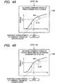
- the manager ECU 4 may cause the engine ECU 6 to set the engine power to be smaller than the predetermined engine power (command torque) at a predetermined ratio of the command torque since the time t1 (see the dashed line DL1A in step 170A of Fig. 4A).
- the manager ECU 4 may cause the engine ECU 6 to set the engine power to be smaller than the predetermined engine power (command torque) by predetermined amount since the time t1.
- the predetermined amount may be set depending on the magnitude of the absolute value of the difference
- This torque decreasing process allows, when the vehicle V becomes or tends to become the unstable condition of outside turning, the vehicle's load to shift to the front wheel side.
- This load shift permits the tire lateral forces acting on the front wheels FR and FL to increase, making it possible to overcome the unstable condition.
- this torque decreasing process allows, when the vehicle V becomes or tends to become the unstable condition of inside turning, to sufficiently keep the tire lateral forces acting on the rear wheels RR and RL. These sufficient tire lateral forces permit the slips of the rear wheels RR and RL to be avoided, making it possible to overcome the unstable condition.
- step 150 determines whether the vehicle body acceleration dVso is not more than zero. If the determination in step 150 is NO, that is, the vehicle body acceleration dVso is not more than zero, the manager ECU 4 shifts to step 180.
- step 180 the manager ECU 4 calculates the absolute value of the difference between the rolling axle speed Vr and the drive axle speed Vd, and determines whether the absolute value of the difference
- step 180 When the determination in step 180 is YES, that is, the absolute value of the difference
- the determination is NO, that is, the absolute value of the difference
- step 185 the manager ECU 4 determines whether the drive axle speed Vd is faster than the rolling axle speed Vr.
- the determination in step 185 is YES, that is, the drive axle speed Vd is faster than the rolling axle speed Vr, the manager ECU 4 determines that the vehicle V becomes the unstable condition of inward turning, shifting to step 190.
- the determination in step 185 is NO, that is, the drive axle speed Vd is not faster than the rolling axle speed Vr, the manager ECU 4 determines that the vehicle V becomes the unstable condition of outward turning, shifting to step 170 and performing the above torque decreasing process shown in step 170 (170A, 170B).
- step 190 the manager ECU 4 performs torque-increasing process.
- the manager ECU 4 sets the condition for increasing the torque. That is, this torque-increasing process corresponds to a process for increasing the torque that is transferred to the drive axle assembly 11b from the engine 5 according to the driver's intention.
- this torque-increasing process increases the acceleration energy during acceleration to permits the vehicle V from being excessively braked.
- the manager ECU 4 controls the engine ECU 6 to increase the power of the engine 5 (engine power), thereby increasing the torque transferred to the drive axle assembly 11b.
- the engine control signal outputted from the engine ECU 6 including a command that causes the engine 5 to output predetermined engine power corresponding to the position of the accelerator pedal 30.
- the manager ECU 4 therefore, outputs to the engine ECU 6 the control signal requesting the engine ECU 6 to increase the predetermined engine power determined by the engine control signal.
- the engine ECU 6 adjusts the command torque corresponding to the predetermined engine power of the engine control signal independently of the position of the accelerator pedal 30.
- step 190 of Fig. 3 a temporal characteristic of the command torque transferred to the drive axle assembly 11b in response to the change of the accelerator pedal's position by the driver's operation is illustrated in step 190 of Fig. 3. This characteristic is obtained in a case where no driving condition control processes shown in Fig. 3 are performed (see solid curved line in step 190).
- the manager ECU 4 when determining that the vehicle V becomes the unstable condition of inward turning at an arbitrary time t2, the manager ECU 4 outputs to the engine ECU 6 the control signal requesting the engine ECU 6 to increase the predetermined engine power (command torque) determined by the engine control signal since the time t2.
- the engine ECU 6 adjusts the predetermined engine power (command torque) of the engine control signal independently of the position of the accelerator pedal 30.
- the manager ECU 4 may make the engine ECU 6 keep the predetermined engine power (command torque CT2), which is previously set at the time t2, since the time t2 (see the dashed line DL2 in step 190).
- command torque CT2 the predetermined engine power
- the manager ECU 4 may cause the engine ECU 6 to set the engine power to be larger than the predetermined engine power (command torque) at a predetermined ratio of the command torque since the time t2 (see the dashed line DL2A in step 190A of Fig. 5A).
- the manager ECU 4 may cause the engine ECU 6 to set the engine power to be larger than the predetermined engine power (command torque) by predetermined amount since the time t2.
- the predetermined amount may be set depending on the magnitude of the absolute value of the difference
- This torque increasing process prevents, when the vehicle V becomes or tends to become the unstable condition of inside turning, the braking forces to the rear wheels RR and RL from excessively increasing. This allows the tire lateral forces acting on the rear wheels RR and RL to increase, making it possible to overcome the unstable condition.
- step 170 allows the vehicle's load to shift to the front wheel side. This load shift permits the tire lateral forces acting on the front wheels FR and FL to increase, making it possible to overcome the unstable condition.
- the manager ECU 4 similarly performs the above processes shown in steps 180, 185, and 190, thereby overcoming the unstable condition of inside turning or that of outside turning.
- this first embodiment it is possible to detect the unstable condition of the vehicle V according to the rotational speeds of the rolling axle (front axle) 11a and the rear axle (drive axle) 11 b. That is, using the rotational conditions of the front and rear axle assemblies 11a and 11b, which cause the yaw moment, permits the unstable conditions of the vehicle V to be detected. As a result, if the driving condition of the vehicle V is different from the driver's intended condition, such as, the vehicle V turns in oversteer or understeer, it is possible to rapidly precisely detect the unstable driving condition of the vehicle V.
- Executing the feedback controls, such as the torque adjusting operations, based on rapidly and precisely detecting the unstable conditions of the vehicle V allows the unstable conditions to be rapidly precisely overcome.
- the manager ECU 4 carries out the increasing and decreasing of the engine power to adjust the torque transferred to the drive axle assembly 11b, thereby overcoming the unstable conditions of the vehicle V.
- the manager ECU 4 of the driving condition control system adjusts the torque based on another processes.
- the manager ECU 4 carries out the adjustment of the torque based on the braking force.
- Processes executed by the manager ECU 4 according to the second embodiment are partially different from those executed by the manager ECU 4 according to the first embodiment so that these partially different processes of the management ECU 4 according to the second embodiment will be explained hereinafter.
- the remaining processes and the structure of the driving condition control system according to the second embodiment are substantially identical with those of the driving condition control system according to the first embodiment, so that explanations thereabout are omitted.
- the manager ECU 4 makes the brake ECU 9 perform the brake force generation process through each of the brake force generating units 10a-10d without adjusting the command torque included in the engine control signal.
- the management ECU 4 for decreasing the torque, outputs to the brake ECU 9 the control signal requesting the brake ECU 9 to generate the brake force (step 170C).
- the brake ECU 9 produces the brake control signal in response to the reception of the control signal outputted form the manager ECU 4, thereby outputting the brake control signal to each of the brake force generating units 10a-10d.
- Each of the brake force generating units 10a-10d applies the brake force (mechanical force) on each of the brake shoes, thereby braking each of the wheels FR, FL, RR, and RL.
- the brake forces applied on the front and rear wheels FR, FL, RR, and RL may be approximately constant, or may be differently distributed between the front wheels FR, FL and the rear wheels RR, RL.
- the brake forces applied on the front and rear wheels FR, FL, RR, and RL may also be differently distributed between the inside wheels and the outside wheels during turning.
- This structure allows the torque transferred to the drive axle assembly 11b to be smaller than predetermined torque.
- the predetermined torque corresponds to the position of the accelerator pedal 30 (driver's intention) when the driving condition of the vehicle V is stable.
- the manager ECU 4 makes the brake ECU 9 adjust the brake forces, which have already been generated during braking, through the brake force generating units 10a-10d without adjusting the command torque included in the engine control signal.
- the management ECU 4 for increasing the torque, outputs to the brake ECU 9 the control signal requesting the brake ECU 9 to adjust the brake forces which have already been generated during braking (step 190C).
- the brake ECU 9 produces the brake control signal that requests each of the brake force generating units 10a-10d to weak each of the brake forces generated thereby according to the driver's operated position of the brake pedal 32 in response to the reception of the control signal outputted form the manager ECU 4.
- the brake ECU 9 outputs the brake control signal to each of the brake force generating units 10a-10d.
- Each of the brake force generating units 10a-10d weaken the brake force (mechanical force) on each of the brake shoes independently of the driver's intention, thereby braking each of the wheels FR, FL, RR, and RL with the weakened brake force.
- the brake forces applied on the front and rear wheels FR, FL, RR, and RL may be approximately constant, or may be differently distributed between the front wheels FR, FL and the rear wheels RR, RL.
- the brake forces applied on the front and rear wheels FR, FL, RR, and RL may also be differently distributed between the inside wheels and the outside wheels during turning.
- the management ECU 4 may make the brake ECU 9 control to distribute that the magnitude of brake forces to the front wheels FR and FL is smaller than that of brake forces to the rear wheels RR and RL.
- the management ECU 4 may make the brake ECU 9 control to distribute that the magnitude of brake forces to the front wheels FR and FL is larger than that of brake forces to the rear wheels RR and RL.
- This structure allows the torque transferred to the drive axle assembly 11b to be larger than predetermined torque.
- the predetermined torque corresponds to the position of the accelerator pedal 30 (driver's intention) when the driving condition of the vehicle V is stable.
- These vehicle driving condition control processes according to the first and second embodiments can be performed at any time during the running of the vehicle.
- the turning centers of the front wheels FR, FL and the rear wheels RR, RL may be different from each other. This may cause that the criterion in that "the drive axle speed Vd is faster than the rolling axle speed Vr" for determining whether the driving condition of the vehicle is the unstable condition of inside turning or the unstable condition of outside turning is changed.
- the manager ECU 4 therefore, may pause the driving condition control processes shown in Figs. 3-5 When the vehicle 5 runs at very low speed, starts moving, or slows down just before stopping.
- the manager ECU 4 when performing the process in step 185, may correct the criterion in that "the drive axle speed Vd is faster than the rolling axle speed Vr" according to the differences of the turning centers of the wheels, and performs the determining process based on the amended criterion.
- the adjustment of the torque is performed by adjusting the engine power or the brake force.
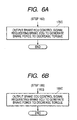
- the management ECU 4 for decreasing the torque, may output to the transmission ECU 8 the control signal requesting the transmission ECU 8 to generate the transmission signal for changing the gear ratios to decrease the engine power corresponding to the driver's intention (Fig. 7A; step 170D), or to increase the engine power corresponding to the driver's intension (Fig. 7B; step 190D).
- These controls of the gear ratios allow the torque transferred to the drive axle assembly 11b to be adjusted.
- the driving condition control system can overcome the unstable condition of the vehicle V at any time during the running of the vehicle V.
- the manager ECU 4 when determining the driver's operation of the steering wheel 12 (Fig. 8; step 108), shifts to step 110 (step 109) to perform these processes in steps 110-190 according to the flowcharts shown in Figs. 3-8. That is, in this modification, it is possible to perform the driving condition control processes only when the vehicle V is turning.
- these steps (processes) shown in Figs. 3-8 are performed by the manager ECU 4, but they may be performed by at least two of the ECUs in combination, or other one of the ECUs. These steps (processes) shown in Figs. 3-8 in combination or alone correspond to processing units of the present invention.
- the driving condition control system according to the present invention may provide a plurality of hard-wired logic circuits that perform these processes in place of the manager ECU 4.
- each of the driving condition control systems according to the first and second embodiments and modifications thereof may be installed in another vehicle, such as two-wheel automobile.
Landscapes
- Engineering & Computer Science (AREA)
- Transportation (AREA)
- Mechanical Engineering (AREA)
- Chemical & Material Sciences (AREA)
- Combustion & Propulsion (AREA)
- Regulating Braking Force (AREA)
- Control Of Driving Devices And Active Controlling Of Vehicle (AREA)
- Control Of Vehicle Engines Or Engines For Specific Uses (AREA)
- Controls For Constant Speed Travelling (AREA)
- Arrangement And Driving Of Transmission Devices (AREA)
- Arrangement And Mounting Of Devices That Control Transmission Of Motive Force (AREA)
Applications Claiming Priority (2)
| Application Number | Priority Date | Filing Date | Title |
|---|---|---|---|
| JP2003173854 | 2003-06-18 | ||
| JP2003173854A JP4148038B2 (ja) | 2003-06-18 | 2003-06-18 | 車両走行状態制御システムおよび車両走行状態制御方法 |
Publications (3)
| Publication Number | Publication Date |
|---|---|
| EP1488974A2 true EP1488974A2 (fr) | 2004-12-22 |
| EP1488974A3 EP1488974A3 (fr) | 2009-12-23 |
| EP1488974B1 EP1488974B1 (fr) | 2012-11-21 |
Family
ID=33410958
Family Applications (1)
| Application Number | Title | Priority Date | Filing Date |
|---|---|---|---|
| EP04014405A Expired - Fee Related EP1488974B1 (fr) | 2003-06-18 | 2004-06-18 | Système et procédé de commande d'entraînement pour detecter une instabilité d'un véhicule |
Country Status (3)
| Country | Link |
|---|---|
| US (1) | US7169083B2 (fr) |
| EP (1) | EP1488974B1 (fr) |
| JP (1) | JP4148038B2 (fr) |
Cited By (2)
| Publication number | Priority date | Publication date | Assignee | Title |
|---|---|---|---|---|
| WO2014009033A1 (fr) * | 2012-07-10 | 2014-01-16 | Robert Bosch Gmbh | Procédé de stabilisation d'un deux roues en conduite en virage |
| WO2014206642A1 (fr) * | 2013-06-28 | 2014-12-31 | Robert Bosch Gmbh | Procédé permettant la stabilisation dynamique transversale d'un véhicule automobile à deux roues |
Families Citing this family (9)
| Publication number | Priority date | Publication date | Assignee | Title |
|---|---|---|---|---|
| JP2005008019A (ja) * | 2003-06-18 | 2005-01-13 | Denso Corp | 車両走行状態制御システムおよび車両走行状態制御方法 |
| AT7181U1 (de) * | 2003-10-31 | 2004-11-25 | Magna Steyr Fahrzeugtechnik Ag | Verfahren zur schadensbegrenzung bei teilüberdeckter frontalkollision und kraftfahrzeug mit einer dazu dienenden vorrichtung |
| US7966113B2 (en) * | 2005-08-25 | 2011-06-21 | Robert Bosch Gmbh | Vehicle stability control system |
| DE102005053864A1 (de) * | 2005-11-11 | 2007-05-16 | Bosch Gmbh Robert | Fahrdynamikregelungssystem mit erweiterter Bremsfunktion |
| JP4938598B2 (ja) * | 2007-09-06 | 2012-05-23 | トヨタ自動車株式会社 | 車両制御装置 |
| US8868281B2 (en) * | 2010-10-28 | 2014-10-21 | GM Global Technology Operations LLC | Understeer assessment for vehicles |
| DE102011079149A1 (de) * | 2011-07-14 | 2013-01-17 | Robert Bosch Gmbh | Verfahren zur Motormomenteneinstellung |
| JP5974458B2 (ja) * | 2011-11-24 | 2016-08-23 | 株式会社ジェイテクト | 車両姿勢制御装置 |
| KR20210148635A (ko) * | 2020-06-01 | 2021-12-08 | 현대모비스 주식회사 | 차량의 제동장치 및 방법 |
Citations (3)
| Publication number | Priority date | Publication date | Assignee | Title |
|---|---|---|---|---|
| JPH03116686A (ja) | 1989-09-29 | 1991-05-17 | Toshiba Lighting & Technol Corp | 放電灯点灯装置 |
| JPH08207542A (ja) | 1995-02-02 | 1996-08-13 | Honda Motor Co Ltd | 車両の旋回運動制御装置 |
| JP2003173854A (ja) | 2001-12-05 | 2003-06-20 | Yazaki Corp | 端子圧着型およびそれを有する端子圧着機 |
Family Cites Families (19)
| Publication number | Priority date | Publication date | Assignee | Title |
|---|---|---|---|---|
| DE3505455A1 (de) * | 1985-02-16 | 1986-08-28 | Daimler-Benz Ag, 7000 Stuttgart | Vorrichtung zum automatischen zu- und abschalten von antriebselementen eines kraftfahrzeuges |
| US5151861A (en) * | 1989-02-22 | 1992-09-29 | Mitsubishi Jidosha Kogyo Kabushiki Kaisha | Vehicle engine output control method and vehicle engine |
| US5172319A (en) * | 1989-11-13 | 1992-12-15 | Honda Giken Kogyo Kabushiki Kaisha | Drive wheel slip control system for vehicle |
| DE3939069C2 (de) * | 1989-11-25 | 2002-07-04 | Bosch Gmbh Robert | Kraftfahrzeug |
| US5141071A (en) * | 1990-03-13 | 1992-08-25 | Mazda Motor Corporation | Four-wheel-steered vehicle control system |
| JP3393654B2 (ja) * | 1991-12-25 | 2003-04-07 | マツダ株式会社 | 車両のスリップ制御装置 |
| DE4201675C1 (fr) * | 1992-01-23 | 1993-05-19 | Mercedes-Benz Aktiengesellschaft, 7000 Stuttgart, De | |
| US5332060A (en) * | 1993-03-10 | 1994-07-26 | New Venture Gear, Inc. | Linear actuation mechanism for electronically-controlled torque modulated transfer case |
| JP3116686B2 (ja) | 1993-10-14 | 2000-12-11 | 三菱自動車工業株式会社 | 車両用左右駆動力調整装置 |
| JP3116738B2 (ja) * | 1994-07-28 | 2000-12-11 | トヨタ自動車株式会社 | 車輌の挙動制御装置 |
| DE19607185A1 (de) * | 1996-02-27 | 1997-08-28 | Bayerische Motoren Werke Ag | Verfahren zur Sicherstellung eines neutralen Fahrverhaltens bei Kurvenfahrten und gleichzeitigem Lastwechsel |
| DE19733674A1 (de) * | 1997-08-04 | 1999-02-11 | Itt Mfg Enterprises Inc | Verfahren zur Erhöhung der Fahrstabilität eines Kraftfahrzeugs |
| JP3972431B2 (ja) * | 1997-11-05 | 2007-09-05 | トヨタ自動車株式会社 | 四輪駆動車のトラクション制御装置 |
| DE19913825A1 (de) * | 1999-03-26 | 2000-09-28 | Bosch Gmbh Robert | Regelsystem für ein Fahrzeug |
| US6644428B2 (en) * | 2001-06-04 | 2003-11-11 | Meritor Heavy Vehicle Technology, Llc | Automatic axle traction control |
| US6466857B1 (en) * | 2001-12-05 | 2002-10-15 | Delphi Technologies, Inc. | Drive wheel traction control during vehicle stability enhancement events |
| US20030230933A1 (en) * | 2002-06-17 | 2003-12-18 | Ford Motor Company | Control of regenerative braking during a yaw stability control event |
| US6691013B1 (en) * | 2002-09-06 | 2004-02-10 | Ford Motor Company | Braking and controllability control method and system for a vehicle with regenerative braking |
| US6923514B1 (en) * | 2003-03-12 | 2005-08-02 | Kelsey-Hayes Company | Electronic brake control system |
-
2003
- 2003-06-18 JP JP2003173854A patent/JP4148038B2/ja not_active Expired - Fee Related
-
2004
- 2004-06-17 US US10/869,033 patent/US7169083B2/en not_active Expired - Fee Related
- 2004-06-18 EP EP04014405A patent/EP1488974B1/fr not_active Expired - Fee Related
Patent Citations (3)
| Publication number | Priority date | Publication date | Assignee | Title |
|---|---|---|---|---|
| JPH03116686A (ja) | 1989-09-29 | 1991-05-17 | Toshiba Lighting & Technol Corp | 放電灯点灯装置 |
| JPH08207542A (ja) | 1995-02-02 | 1996-08-13 | Honda Motor Co Ltd | 車両の旋回運動制御装置 |
| JP2003173854A (ja) | 2001-12-05 | 2003-06-20 | Yazaki Corp | 端子圧着型およびそれを有する端子圧着機 |
Cited By (4)
| Publication number | Priority date | Publication date | Assignee | Title |
|---|---|---|---|---|
| WO2014009033A1 (fr) * | 2012-07-10 | 2014-01-16 | Robert Bosch Gmbh | Procédé de stabilisation d'un deux roues en conduite en virage |
| US9573590B2 (en) | 2012-07-10 | 2017-02-21 | Robert Bosch Gmbh | Method for stabilizing a two-wheeled vehicle during cornering |
| WO2014206642A1 (fr) * | 2013-06-28 | 2014-12-31 | Robert Bosch Gmbh | Procédé permettant la stabilisation dynamique transversale d'un véhicule automobile à deux roues |
| US9937967B2 (en) | 2013-06-28 | 2018-04-10 | Robert Bosch Gmbh | Method for lateral dynamic stabilization of a single-track motor vehicle |
Also Published As
| Publication number | Publication date |
|---|---|
| JP2005009390A (ja) | 2005-01-13 |
| US20040262067A1 (en) | 2004-12-30 |
| JP4148038B2 (ja) | 2008-09-10 |
| EP1488974A3 (fr) | 2009-12-23 |
| US7169083B2 (en) | 2007-01-30 |
| EP1488974B1 (fr) | 2012-11-21 |
Similar Documents
| Publication | Publication Date | Title |
|---|---|---|
| JP3937524B2 (ja) | 車輌の制駆動力制御装置 | |
| US5850616A (en) | Traction control system for four wheel drive vehicle and the method thereof | |
| CN108466611B (zh) | 四轮驱动车辆的控制装置 | |
| US6453228B1 (en) | Vehicle drive force control system and method | |
| JP4285902B2 (ja) | 横転を回避するための車両の安定化方法および装置 | |
| US7640081B2 (en) | Roll stability control using four-wheel drive | |
| US5701247A (en) | Integrated control system for 4WD vehicles for controlling driving torque distribution | |
| EP2014530B1 (fr) | Dispositif pour le contrôle de rotation d'un véhicule | |
| CN100343108C (zh) | 车辆稳定性控制设备 | |
| JP4886848B2 (ja) | 車両制御に基づく制動減速の補償方法 | |
| US20020014799A1 (en) | Vehicular brake control apparatus and vehicular brake control method | |
| US5471390A (en) | Differential limiting torque control system for automotive vehicles | |
| JP2009505886A (ja) | 車両安定性制御システム | |
| JPH0729557B2 (ja) | 四輪駆動車の駆動力配分制御装置 | |
| US20080208427A1 (en) | Vehicle braking-force control device | |
| US20180281760A1 (en) | Control device for four-wheel drive vehicle | |
| US11285809B2 (en) | Travel control apparatus for four-wheel drive vehicle | |
| JPH10295004A (ja) | 電気自動車用駆動制御装置 | |
| EP1488974B1 (fr) | Système et procédé de commande d'entraînement pour detecter une instabilité d'un véhicule | |
| JP3607985B2 (ja) | 車輌の車体速度推定装置及び制御装置 | |
| JP4114065B2 (ja) | 四輪駆動車の挙動制御装置 | |
| JP6520890B2 (ja) | 四輪駆動車の挙動制御装置 | |
| CN108025709B (zh) | 机动车牵引力控制系统和方法 | |
| US7241249B2 (en) | Driving condition control method and system | |
| JP4019925B2 (ja) | ロール状態判断装置 |
Legal Events
| Date | Code | Title | Description |
|---|---|---|---|
| PUAI | Public reference made under article 153(3) epc to a published international application that has entered the european phase |
Free format text: ORIGINAL CODE: 0009012 |
|
| AK | Designated contracting states |
Kind code of ref document: A2 Designated state(s): AT BE BG CH CY CZ DE DK EE ES FI FR GB GR HU IE IT LI LU MC NL PL PT RO SE SI SK TR |
|
| AX | Request for extension of the european patent |
Extension state: AL HR LT LV MK |
|
| PUAL | Search report despatched |
Free format text: ORIGINAL CODE: 0009013 |
|
| AK | Designated contracting states |
Kind code of ref document: A3 Designated state(s): AT BE BG CH CY CZ DE DK EE ES FI FR GB GR HU IE IT LI LU MC NL PL PT RO SE SI SK TR |
|
| AX | Request for extension of the european patent |
Extension state: AL HR LT LV MK |
|
| 17P | Request for examination filed |
Effective date: 20100616 |
|
| AKX | Designation fees paid |
Designated state(s): DE FR GB |
|
| 17Q | First examination report despatched |
Effective date: 20110222 |
|
| GRAP | Despatch of communication of intention to grant a patent |
Free format text: ORIGINAL CODE: EPIDOSNIGR1 |
|
| RIC1 | Information provided on ipc code assigned before grant |
Ipc: B60W 30/045 20120101ALI20120419BHEP Ipc: B60K 28/16 20060101ALI20120419BHEP Ipc: B60W 10/184 20120101ALI20120419BHEP Ipc: B60W 10/06 20060101ALI20120419BHEP Ipc: B60T 8/00 20060101AFI20120419BHEP Ipc: B60K 23/08 20060101ALI20120419BHEP |
|
| GRAS | Grant fee paid |
Free format text: ORIGINAL CODE: EPIDOSNIGR3 |
|
| GRAA | (expected) grant |
Free format text: ORIGINAL CODE: 0009210 |
|
| AK | Designated contracting states |
Kind code of ref document: B1 Designated state(s): DE FR GB |
|
| REG | Reference to a national code |
Ref country code: GB Ref legal event code: FG4D |
|
| REG | Reference to a national code |
Ref country code: DE Ref legal event code: R096 Ref document number: 602004040095 Country of ref document: DE Effective date: 20130117 |
|
| PLBE | No opposition filed within time limit |
Free format text: ORIGINAL CODE: 0009261 |
|
| STAA | Information on the status of an ep patent application or granted ep patent |
Free format text: STATUS: NO OPPOSITION FILED WITHIN TIME LIMIT |
|
| 26N | No opposition filed |
Effective date: 20130822 |
|
| REG | Reference to a national code |
Ref country code: DE Ref legal event code: R084 Ref document number: 602004040095 Country of ref document: DE Effective date: 20130917 |
|
| REG | Reference to a national code |
Ref country code: GB Ref legal event code: 746 Effective date: 20131106 |
|
| REG | Reference to a national code |
Ref country code: DE Ref legal event code: R097 Ref document number: 602004040095 Country of ref document: DE Effective date: 20130822 |
|
| REG | Reference to a national code |
Ref country code: FR Ref legal event code: PLFP Year of fee payment: 12 |
|
| REG | Reference to a national code |
Ref country code: FR Ref legal event code: PLFP Year of fee payment: 13 |
|
| PGFP | Annual fee paid to national office [announced via postgrant information from national office to epo] |
Ref country code: GB Payment date: 20160621 Year of fee payment: 13 Ref country code: DE Payment date: 20160621 Year of fee payment: 13 |
|
| PGFP | Annual fee paid to national office [announced via postgrant information from national office to epo] |
Ref country code: FR Payment date: 20160627 Year of fee payment: 13 |
|
| REG | Reference to a national code |
Ref country code: DE Ref legal event code: R119 Ref document number: 602004040095 Country of ref document: DE |
|
| GBPC | Gb: european patent ceased through non-payment of renewal fee |
Effective date: 20170618 |
|
| REG | Reference to a national code |
Ref country code: FR Ref legal event code: ST Effective date: 20180228 |
|
| PG25 | Lapsed in a contracting state [announced via postgrant information from national office to epo] |
Ref country code: GB Free format text: LAPSE BECAUSE OF NON-PAYMENT OF DUE FEES Effective date: 20170618 Ref country code: DE Free format text: LAPSE BECAUSE OF NON-PAYMENT OF DUE FEES Effective date: 20180103 |
|
| PG25 | Lapsed in a contracting state [announced via postgrant information from national office to epo] |
Ref country code: FR Free format text: LAPSE BECAUSE OF NON-PAYMENT OF DUE FEES Effective date: 20170630 |