EP1486739A2 - Verfahren und Vorrichtung zum geruchsfreien Betrieb einer Klimaanlage - Google Patents
Verfahren und Vorrichtung zum geruchsfreien Betrieb einer Klimaanlage Download PDFInfo
- Publication number
- EP1486739A2 EP1486739A2 EP04076560A EP04076560A EP1486739A2 EP 1486739 A2 EP1486739 A2 EP 1486739A2 EP 04076560 A EP04076560 A EP 04076560A EP 04076560 A EP04076560 A EP 04076560A EP 1486739 A2 EP1486739 A2 EP 1486739A2
- Authority
- EP
- European Patent Office
- Prior art keywords
- evaporator
- temperature
- condensate
- temperature sensor
- air
- Prior art date
- Legal status (The legal status is an assumption and is not a legal conclusion. Google has not performed a legal analysis and makes no representation as to the accuracy of the status listed.)
- Withdrawn
Links
Images
Classifications
-
- F—MECHANICAL ENGINEERING; LIGHTING; HEATING; WEAPONS; BLASTING
- F24—HEATING; RANGES; VENTILATING
- F24F—AIR-CONDITIONING; AIR-HUMIDIFICATION; VENTILATION; USE OF AIR CURRENTS FOR SCREENING
- F24F11/00—Control or safety arrangements
- F24F11/30—Control or safety arrangements for purposes related to the operation of the system, e.g. for safety or monitoring
-
- F—MECHANICAL ENGINEERING; LIGHTING; HEATING; WEAPONS; BLASTING
- F24—HEATING; RANGES; VENTILATING
- F24F—AIR-CONDITIONING; AIR-HUMIDIFICATION; VENTILATION; USE OF AIR CURRENTS FOR SCREENING
- F24F11/00—Control or safety arrangements
- F24F11/62—Control or safety arrangements characterised by the type of control or by internal processing, e.g. using fuzzy logic, adaptive control or estimation of values
- F24F11/63—Electronic processing
- F24F11/65—Electronic processing for selecting an operating mode
- F24F11/66—Sleep mode
-
- F—MECHANICAL ENGINEERING; LIGHTING; HEATING; WEAPONS; BLASTING
- F24—HEATING; RANGES; VENTILATING
- F24F—AIR-CONDITIONING; AIR-HUMIDIFICATION; VENTILATION; USE OF AIR CURRENTS FOR SCREENING
- F24F2110/00—Control inputs relating to air properties
Definitions
- This invention relates to a vehicle air conditioning or climate control system, and more particularly to a method and apparatus for biasing the operating point of the system as required to prevent the build-up of odor producing microorganisms.
- the present invention is directed to an improved air conditioning method and apparatus including an evaporator that is chilled by refrigerant, where the presence of sufficient condensate flow for odor-free operation is detected based on the surface temperature of a thermistor or other electrically activated temperature sensor disposed in a condensate drainpipe of the evaporator.
- the surface temperature of the drainpipe sensor is used to calculate the temperature of a stagnant fluid (air or water) in the drainpipe based on the power supplied to the sensor and the convective heat transfer characteristics of air and water. If the calculated temperature of stagnant air is approximately equal to the evaporator temperature, it is deduced that there is little or no condensate flow through the drainpipe; in this case, the evaporator is too dry and the operating point of the air conditioning system is lowered to reduce the surface temperature of the evaporator. If the calculated temperature of stagnant water is approximately equal to the evaporator temperature, it is deduced that the drainpipe is plugged; in this case, the refrigerant compressor is disabled and the operator is advised to have the air conditioning system serviced. Otherwise, the evaporator is deemed to be generating sufficient condensate to cleanse the evaporator surface of odor causing microorganisms, and there is no adjustment of the operating point of the air conditioning system.
- a constant power is supplied to the drainpipe sensor, and the state of the evaporator is deduced by comparing the surface temperature of the sensor to a set of predefined reference temperatures.
- the predefined reference temperatures are experimentally determined for different operating conditions of the evaporator, including at least a condition for which the evaporator is too dry, and a condition for which the evaporator drainpipe is plugged. If it is deduced that the evaporator is too dry, the operating point of the air conditioning system is lowered to reduce the surface temperature of the evaporator. If it is deduced that the drainpipe is plugged, the refrigerant compressor is disabled and the operator is advised to have the air conditioning system serviced.
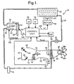
- the present invention is described in the context of an automatic climate control system 10 for a motor vehicle, including a refrigerant compressor 12 coupled to a rotary shaft of the vehicle engine (not shown) via drive pulley 14, electrically activated clutch 16, and drive belt 18.
- the compressor 12 has a variable stroke for adjusting its capacity and an electrically activated stroke control valve 17 for controlling the compressor capacity.
- the valve 17 may be pneumatically controlled, or the compressor 12 may have a fixed displacement, in which cases the compressor capacity can be controlled through selective activation and deactivation of the clutch 16.
- a condenser 20, an orifice tube 22, an evaporator 24, and an accumulator/dehydrator 26 are arranged in order between the compressor discharge port 28 and suction port 30 of compressor 12.
- a cooling fan 32 operated by an electric drive motor 34, is controlled to provide supplemental air flow through the condenser 20 for removing heat from the high pressure refrigerant in condenser 20.
- the orifice tube 22 allows the cooled high pressure refrigerant in line 38 to expand in an isenthalpic fashion before passing through the evaporator 24.
- the accumulator/dehydrator 26 separates low pressure gaseous and liquid refrigerant, directs gaseous refrigerant to the compressor suction port 30, and stores excess refrigerant that is not in circulation.
- the orifice tube 22 is replaced with a thermostatic expansion valve (TXV); in this case, the accumulator/ dehydrator 26 is omitted, and a receiver/drier (R/D) is inserted in line 38 upstream of the TXV to ensure that sub-cooled liquid refrigerant is available at the TXV inlet.
- TXV thermostatic expansion valve
- R/D receiver/drier
- the evaporator 24 is formed as an array of finned refrigerant conducting tubes, and an air intake duct 40 disposed on one side of evaporator 24 houses a motor driven ventilation blower 42 driven by an electric blower motor 43 for forcing air past the evaporator tubes.
- the duct 40 is bifurcated upstream of the blower 42, and an inlet air control door 44 is adjustable as shown to control inlet air mixing; depending on the door position, outside air may enter blower 42 through duct leg 44a, and passenger compartment air may enter blower 42 through duct leg 44b.
- An air outlet duct 52 disposed on the downstream side of blower 42 and evaporator 24 houses a heater core 54 formed as an array of finned tubes through which flows engine coolant.
- the heater core 54 effectively bifurcates the outlet duct 52, and a temperature door 56 is adjustable as shown to control how much of the air must pass through the heater core 54.
- the heated and unheated air portions are mixed in a plenum portion 62 of outlet duct 52 downstream of temperature door 56, and a pair of mode control doors 64, 66 direct the mixed air through one or more outlets, including a defrost outlet 68, a panel outlet 70, and a heater outlet 72.
- the inlet air drawn through duct legs 44a, 44b passing the finned tubes of evaporator 24 is chilled, causing water vapor in the air to condense on the cold evaporator surface. If the surface temperature of the evaporator 24 is below the dewpoint temperature of the inlet air, the evaporator surface collects copious amounts of condensate which cleanses the evaporator surface of odor-causing microorganisms. In any event, the condensate collects near the bottom of evaporator 24, and is exhausted beneath the vehicle via the drainpipe 80.
- the above-described system 10 is controlled by the microprocessor-based control unit 90 based on various input signals, including those generated by ambient air temperature (AT) sensor 92, in-car (IC) temperature sensor 94, and evaporator outlet air temperature (T eoat ) sensor 96.
- the temperature sensor 96 is disposed in the outlet airstream of evaporator 24 so that the signal T eoat closely approximates the surface temperature of evaporator 24.
- Other inputs not shown in Figure 1 include the usual operator demand inputs generated by the driver interface panel (DIP) 98, such as a desired cabin air temperature, and override controls for fan and mode.
- DIP driver interface panel
- a further input according to this invention is provided by a thermistor 82 located in the evaporator condensate drainpipe 80. As explained below, thermistor 82 is used to deduce the state of the evaporator 24 for purposes of ensuring odor-free operation of the system 10.
- the control unit 90 develops output signals for controlling the compressor clutch 16, the capacity control valve 17, the fan motor 34, the blower motor 43, and the air control doors 44, 56, 64 and 66.
- the output signal CL for the clutch 16 appears on line 100
- the output signal STROKE for valve 17 appears on line 102
- the output signal FC for condenser fan motor 34 appears on line 104.
- output signals and actuators for the air control doors 44, 56, 64, 66 have been omitted.
- the control unit 90 has the capability of generating output signals to the driver interface panel 98, such as for alerting the driver of conditions that require servicing of the system 10.
- the control unit 90 may be programmed to carry out a number of different control strategies or algorithms for controlling the capacity of compressor 12.
- Traditional control strategies attempt to maximize evaporator cooling while preventing the formation of ice on the evaporator surface.
- Other control strategies such as described in the U.S. Patent No. 6,293,116 to Forrest et al., provide increased energy efficiency by controlling the compressor capacity to a level that achieves a desired humidity level in the vehicle cabin while minimizing re-heating of the conditioned air.
- Any control strategy, but particularly the high efficiency control strategies can result in an evaporator condition favorable to the build-up of odor-causing microorganisms.
- this invention provides a cost effective method and apparatus for detecting a dry or low-condensate-flow condition of the evaporator 24, in which case the capacity of the compressor can be increased to increase condensate flow for odor-free operation of the system 10.
- the thermistor 82 may be mounted in the condensate drainpipe 80 substantially as shown.
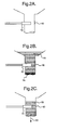
- Figure 2A illustrates a condition where there is little or no condensate flow, and the thermistor 82 is surrounded by essentially stagnant air; the air flow is considered to be stagnant since the amount of evaporator-conditioned air escaping through the drainpipe 80 is negligible compared with the amount of air flowing through the outlets 68, 70, 72.
- Figure 2B illustrates a condition where the drainpipe 80 is blocked by foreign matter 84, and the thermistor 82 is surrounded by essentially stagnant water 86.
- Figure 2C illustrates a condition where there is a continuous flow of condensate 88 (indicated by arrow 89), as occurs when the evaporator surface temperature is below the dewpoint temperature of the inlet air.
- the thermistor 82 may be partially or fully contacted by flowing
- the relationship between the surface temperature T s of thermistor 82 and its electric resistance R t for commonly used thermistor materials in which R t decreases with increasing T s is expressible as: where R o is the electrical resistance of thermistor 82 at reference temperature T o and ⁇ is the temperature coefficient of the thermistor material in °R.
- R o is the electrical resistance of thermistor 82 at reference temperature T o
- ⁇ is the temperature coefficient of the thermistor material in °R.
- the surface temperature T s is used to calculate the temperature of a stagnant fluid (air or water) in the drainpipe based on the power supplied to thermistor 82 and the convective heat transfer characteristics of air and water. If the calculated temperature for air T fa is approximately equal to the evaporator temperature T eoat , the thermistor 82 is surrounded primarily by stagnant air, and it is deduced that there is little or no condensate flow through the drainpipe 80. In this case, the evaporator 24 is too dry and the operating point of the air conditioning system 10 is lowered to reduce the surface temperature of the evaporator 24.
- the thermistor 82 is surrounded primarily by stagnant condensate, and it is deduced that the drainpipe 80 is plugged. In this case, the compressor clutch 16 is turned off and the operator is advised via driver interface panel 98 to have the air conditioning system 10 serviced. Otherwise, the evaporator 24 is deemed to be generating sufficient condensate to cleanse the evaporator surface of odor causing microorganisms, and there is no adjustment of the operating point of the air conditioning system 10.
- the temperature T f of a circumambient fluid in drainpipe 80 may be expressed in terms of the thermistor surface temperature T s as follows: where W is the electrical power in Watts supplied to the thermistor 82, d and ⁇ are the thermistor diameter and length dimensions in feet, and h is the convective heat transfer coefficient from the thermistor surface in Btu/ft 2 hr°R.
- W is the electrical power in Watts supplied to the thermistor 82
- d and ⁇ are the thermistor diameter and length dimensions in feet
- h the convective heat transfer coefficient from the thermistor surface in Btu/ft 2 hr°R.
- the fluid surrounding the thermistor 82 is essentially stagnant, and the convective heat transfer coefficient h can be determined using the following natural convection relation for a circular cylinder presented by H.J. Merk and J.A.
- ⁇ , ⁇ , k and ⁇ appearing in equation (6) are specific to the fluid in drainpipe 80.
- the expansion coefficient ⁇ is 0.001887 °R -1 for air, and 0.000176 °R -1 for condensate (water).
- the transport properties ⁇ , ⁇ and k for air and condensate (water) are as follows: Property Air Water ⁇ , 1b m /ft hr 0.0438 2.394 p, 1b m /ft 3 0.0749 62.3 k, Btu/ft hr °R 0.0147 0.347
- T fa T s - 3.4822 W 4/5 d 3/5 ⁇ 4/5 for air
- T fw T s - 0.0766W 4/5 d 3/5 ⁇ 4/5 for water
- control unit 90 compares T fa and T fw to the surface temperature T eoat of the evaporator 24. If T eoat is approximately equal to T fa , the evaporator core is too dry and the operating point of the air conditioning system 10 is lowered to reduce the surface temperature of the evaporator 24.
- T eoat is approximately equal to T fw , the drainpipe 80 is plugged, and the compressor 12 is disabled and the operator is advised via driver interface panel 98 to have the air conditioning system 10 serviced. If T eoat is a value other than T fa or T fw , the evaporator 24 is deemed to be generating sufficient condensate to cleanse the evaporator surface of odor causing microorganisms, and there is no adjustment of the operating point of the air conditioning system 10.
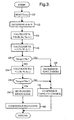
- Figure 3 depicts a flow diagram representative of a software routine periodically executed by the control unit 90 according to the first embodiment of this invention.
- the control is illustrated in the context of a compressor capacity control designated by block 132 which activates stroke control valve 17 as required to achieve a target evaporator outlet air temperature, referred to herein as EOAT_TARGET.
- the activation of stroke control valve 17 is adjusted based on the measured deviation of T eoat from EOAT_TARGET, so as to increase the compressor capacity if T eoat is higher than EOAT_TARGET, and decrease the compressor capacity if T eoat is lower than EOAT_TARGET.
- the control unit 90 adjusts the position of temperature door 56 as required to achieve a desired outlet air temperature, as discussed above.
- T eoat , R t and W are determined at blocks 120 and 122. Thereafter, the thermistor surface temperature T s is calculated at block 124 using equation (6), and the corresponding temperature T fa of stagnant air surrounding the thermistor 82 is calculated at block 126 using equation (7). If T eoat is approximately equal to T fa , as determined at block 128, the evaporator core is too dry and block 130 is executed to lower the operating point of the air conditioning system 10 by decrementing EOAT_TARGET, whereafter the capacity control block 132 is executed. Otherwise, the temperature T fw of stagnant water surrounding the thermistor 82 is calculated at block 134 using equation (8).
- T eoat is approximately equal to T fw , as determined at block 136, the drainpipe 80 is plugged; in this case, blocks 138 and 140 are executed to set a "plugged drain” alert to signal the operator via driver interface panel 98 to have the air conditioning system 10 serviced, and to execute a compressor shutdown routine for disabling further operation of compressor 12 by disengaging the compressor clutch 16. If blocks 128 and 136 are both answered in the negative, the evaporator 24 is deemed to be generating sufficient condensate to cleanse the evaporator surface of odor causing microorganisms, and the system 10 is allowed to continue operating normally.
- the control unit 90 supplies constant power to the thermistor 82, and its surface temperature T s is compared to a set of predefined reference temperatures to deduce the operating state of evaporator 24.
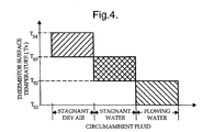
- Figure 4 graphically depicts a set of reference temperatures T s1 , T s2 , T s3 , T s4 determined experimentally under operating conditions of the evaporator 24 that result in three different types of circumambient drainpipe fluid.
- the reference temperatures T s1 and T s2 define a first range of thermistor surface temperatures observed when the surface of evaporator 24 is too dry and the circumambient fluid is stagnant air.
- the thermistor surface temperature T s falls within the first range, the operating point of the system 10 is lowered to reduce the surface temperature of the evaporator 24.
- the reference temperatures T s2 and T s3 define a second range of thermistor surface temperatures observed when the drainpipe 80 is plugged and the circumambient fluid is stagnant water/condensate. If T s falls within the second range, the compressor 12 is disabled and the operator is advised to have the system serviced.
- the reference temperatures T s3 and T s4 define a third range of thermistor surface temperatures observed when the evaporator 24 is generating sufficient condensate to cleanse the evaporator surface of odor causing microorganisms and the circumambient fluid is flowing water/condensate. If T s falls within the third range, the system 10 is allowed to continue operating normally.
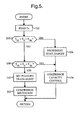
- control method outlined in the preceding paragraph is illustrated by the flow diagram of Figure 5, which represents a software routine periodically executed by the control unit 90 according to the second embodiment of this invention. Similar to the first embodiment, the control according to the second embodiment is illustrated in the context of a compressor capacity control (designated by block 156) which activates stroke control valve 17 as required to achieve a target evaporator outlet air temperature EOAT_TARGET.
- the thermistor surface temperature T s is calculated at block 150 using equation (1).
- T s falls within the temperature range defined by reference temperatures T s3 and T s4 , as determined at block 152, the evaporator core is too dry and block 154 is executed to lower the operating point of the air conditioning system 10 by decrementing EOAT_TARGET, whereafter the capacity control block 156 is executed. If the block 152 is answered in the negative, the block 158 is executed to determine if T s falls within the temperature range defined by reference temperatures T s2 and T s3 .
- the drainpipe 80 is plugged, and the blocks 160 and 162 are executed to set a "plugged drain” alert to signal the operator via driver interface panel 98 to have the air conditioning system 10 serviced, and to execute a compressor shutdown routine for disabling further operation of compressor 12 by disengaging the compressor clutch 16.
- T s is presumed to be lower than the reference temperatures T s2 , which means that the evaporator 24 is generating sufficient condensate to cleanse the evaporator surface of odor causing microorganisms.
- the block 156 is executed to perform the usual compressor capacity control, and the system 10 is allowed to continue operating normally.
- the present invention ensures odor-free operation of an air conditioning system without the use of expensive sensors, and additionally provides detection of a plugged condensate drainpipe. While described in reference to the illustrated embodiment, it is expected that various modifications in addition to those mentioned above will occur to those skilled in the art.
- a hot wire anemometer or other electrically activated temperature sensor may be used instead of the thermistor 82.
- the evaporator surface temperature T eoat may be determined from the evaporator inlet refrigerant pressure, if desired, by calculating the saturation refrigerant temperature in the evaporator to provide a close first order estimate of the discharge air temperature T eoat .
Landscapes
- Engineering & Computer Science (AREA)
- Signal Processing (AREA)
- Chemical & Material Sciences (AREA)
- Combustion & Propulsion (AREA)
- Mechanical Engineering (AREA)
- General Engineering & Computer Science (AREA)
- Physics & Mathematics (AREA)
- Fuzzy Systems (AREA)
- Mathematical Physics (AREA)
- Air Conditioning Control Device (AREA)
- Air-Conditioning For Vehicles (AREA)
Applications Claiming Priority (2)
| Application Number | Priority Date | Filing Date | Title |
|---|---|---|---|
| US460381 | 2003-06-12 | ||
| US10/460,381 US6796135B1 (en) | 2003-06-12 | 2003-06-12 | Method and apparatus for odor-free operation of an air conditioning system |
Publications (2)
| Publication Number | Publication Date |
|---|---|
| EP1486739A2 true EP1486739A2 (de) | 2004-12-15 |
| EP1486739A3 EP1486739A3 (de) | 2010-03-17 |
Family
ID=32990959
Family Applications (1)
| Application Number | Title | Priority Date | Filing Date |
|---|---|---|---|
| EP04076560A Withdrawn EP1486739A3 (de) | 2003-06-12 | 2004-05-27 | Verfahren und Vorrichtung zum geruchsfreien Betrieb einer Klimaanlage |
Country Status (2)
| Country | Link |
|---|---|
| US (1) | US6796135B1 (de) |
| EP (1) | EP1486739A3 (de) |
Cited By (3)
| Publication number | Priority date | Publication date | Assignee | Title |
|---|---|---|---|---|
| WO2009093010A1 (en) * | 2008-01-21 | 2009-07-30 | Charles Austen Pumps Limited | Conduit for a condensate removal pump |
| CN110749049A (zh) * | 2018-07-05 | 2020-02-04 | 青岛海尔空调电子有限公司 | 水冷式空调机组的控制方法 |
| CN112556116A (zh) * | 2020-12-10 | 2021-03-26 | 青岛海尔空调器有限总公司 | 用于空调器的控制方法及装置、空调器 |
Families Citing this family (5)
| Publication number | Priority date | Publication date | Assignee | Title |
|---|---|---|---|---|
| US7779643B2 (en) * | 2005-07-13 | 2010-08-24 | Everett Simons | Refrigeration cycle dehumidifier |
| US8484985B2 (en) * | 2009-03-31 | 2013-07-16 | Delphi Technologies, Inc. | Air conditioner system having an externally controlled variable displacement compressor and a clutch and method of operating the same |
| US8209073B2 (en) * | 2009-05-06 | 2012-06-26 | Ford Global Technologies, Llc | Climate control system and method for optimizing energy consumption of a vehicle |
| CA2736085C (en) * | 2011-03-28 | 2013-05-14 | Fakieh Research & Development Center | Combined air conditioning and water generating system |
| CN115507496B (zh) * | 2022-09-29 | 2024-07-23 | 珠海格力电器股份有限公司 | 空调电加热器的功率补偿控制方法、空调器以及存储介质 |
Citations (2)
| Publication number | Priority date | Publication date | Assignee | Title |
|---|---|---|---|---|
| US6035649A (en) | 1997-07-04 | 2000-03-14 | Daimlerchrysler Ag | Method for controlling the evaporator temperature of an air conditioner as a function of the outside dew point |
| US6293116B1 (en) | 2000-04-10 | 2001-09-25 | Delphi Technologies, Inc. | Humidity control method for a variable capacity vehicle climate control system |
Family Cites Families (6)
| Publication number | Priority date | Publication date | Assignee | Title |
|---|---|---|---|---|
| JP3321857B2 (ja) * | 1992-11-25 | 2002-09-09 | 株式会社デンソー | 空調装置 |
| FR2720340B1 (fr) * | 1994-05-30 | 1996-07-05 | Valeo Thermique Habitacle | Installation de climatisation pour véhicule automobile. |
| US5899082A (en) * | 1997-09-18 | 1999-05-04 | Stein; Myron | Method and apparatus for odor elimination in vehicle air conditioning systems |
| US6470697B2 (en) | 2000-04-27 | 2002-10-29 | Denso Corporation | Air-conditioning system for vehicles |
| JP4654529B2 (ja) | 2000-04-27 | 2011-03-23 | 株式会社デンソー | 車両用空調装置 |
| US6658871B1 (en) * | 2001-04-23 | 2003-12-09 | Airsept, Inc. | Electronic evaporator dryer for eliminating odors in vehicle air conditioning systems |
-
2003
- 2003-06-12 US US10/460,381 patent/US6796135B1/en not_active Expired - Fee Related
-
2004
- 2004-05-27 EP EP04076560A patent/EP1486739A3/de not_active Withdrawn
Patent Citations (2)
| Publication number | Priority date | Publication date | Assignee | Title |
|---|---|---|---|---|
| US6035649A (en) | 1997-07-04 | 2000-03-14 | Daimlerchrysler Ag | Method for controlling the evaporator temperature of an air conditioner as a function of the outside dew point |
| US6293116B1 (en) | 2000-04-10 | 2001-09-25 | Delphi Technologies, Inc. | Humidity control method for a variable capacity vehicle climate control system |
Non-Patent Citations (2)
| Title |
|---|
| H.J.MERK AND J.A.PRINS: "THERMAL CONVECTION IN LAMINAR BOUNDARY LAYERS I,II AND III", APPLIED SCIENTIFIC RESEARCH, vol. A4, pages 11 - 24, 195-221, 1953-1954 |
| M.S.BHATTI: "Enhancement of R-134a Automotive Air Conditioning System", SAE CONFERENCE PAPER, no. 1999-01-0870, 1999, DETROIT |
Cited By (6)
| Publication number | Priority date | Publication date | Assignee | Title |
|---|---|---|---|---|
| WO2009093010A1 (en) * | 2008-01-21 | 2009-07-30 | Charles Austen Pumps Limited | Conduit for a condensate removal pump |
| JP2011510253A (ja) * | 2008-01-21 | 2011-03-31 | チャールズ・オーステン・パンプス・リミテッド | 凝縮水除去ポンプ用導管 |
| RU2488045C2 (ru) * | 2008-01-21 | 2013-07-20 | Чарльз Остен Пампс Лимитед | Трубка для насоса для удаления конденсата |
| US8798449B2 (en) | 2008-01-21 | 2014-08-05 | Charles Austen Pumps Limited | Conduit for a condensation removal pump |
| CN110749049A (zh) * | 2018-07-05 | 2020-02-04 | 青岛海尔空调电子有限公司 | 水冷式空调机组的控制方法 |
| CN112556116A (zh) * | 2020-12-10 | 2021-03-26 | 青岛海尔空调器有限总公司 | 用于空调器的控制方法及装置、空调器 |
Also Published As
| Publication number | Publication date |
|---|---|
| EP1486739A3 (de) | 2010-03-17 |
| US6796135B1 (en) | 2004-09-28 |
Similar Documents
| Publication | Publication Date | Title |
|---|---|---|
| US7434415B2 (en) | System and method for using hot gas reheat for humidity control | |
| US6293116B1 (en) | Humidity control method for a variable capacity vehicle climate control system | |
| US20040079096A1 (en) | Vehicle air conditioning system | |
| US5904052A (en) | Brine type air conditioning apparatus | |
| JP3596345B2 (ja) | 冷凍サイクル装置および車両用空調装置 | |
| US5493870A (en) | Air conditioning apparatus for vehicle | |
| US5560217A (en) | Air conditioning system of heat pump type | |
| JP2003166764A (ja) | 冷凍サイクル装置 | |
| US20040089004A1 (en) | Vehicle air-conditioning system | |
| JP2000219034A (ja) | 空調装置 | |
| JP3651453B2 (ja) | 車両用空調装置 | |
| US6796135B1 (en) | Method and apparatus for odor-free operation of an air conditioning system | |
| JP3799768B2 (ja) | 車両用冷凍サイクル装置 | |
| JP2003336944A (ja) | 輸送車温度制御装置の蒸発器コイルの除霜方法 | |
| JP2008261603A (ja) | 冷凍サイクル装置および車両用空調装置 | |
| JP2001121952A (ja) | 車両用空調装置 | |
| EP1544556A1 (de) | Klimaanlage | |
| JP2004230988A (ja) | 車両用空調装置 | |
| JP2000177368A (ja) | 車両用空調装置 | |
| JP4258217B2 (ja) | 冷凍サイクル装置 | |
| JP3480141B2 (ja) | 車両用空気調和装置 | |
| JP2007269217A (ja) | 冷凍サイクル装置 | |
| JP3478148B2 (ja) | 車両用空調装置 | |
| JP3716459B2 (ja) | 車両用空気調和機 | |
| JPH11342725A (ja) | 車両用空調装置 |
Legal Events
| Date | Code | Title | Description |
|---|---|---|---|
| PUAI | Public reference made under article 153(3) epc to a published international application that has entered the european phase |
Free format text: ORIGINAL CODE: 0009012 |
|
| AK | Designated contracting states |
Kind code of ref document: A2 Designated state(s): AT BE BG CH CY CZ DE DK EE ES FI FR GB GR HU IE IT LI LU MC NL PL PT RO SE SI SK TR |
|
| AX | Request for extension of the european patent |
Extension state: AL HR LT LV MK |
|
| PUAL | Search report despatched |
Free format text: ORIGINAL CODE: 0009013 |
|
| AK | Designated contracting states |
Kind code of ref document: A3 Designated state(s): AT BE BG CH CY CZ DE DK EE ES FI FR GB GR HU IE IT LI LU MC NL PL PT RO SE SI SK TR |
|
| AX | Request for extension of the european patent |
Extension state: AL HR LT LV MK |
|
| AKY | No designation fees paid | ||
| REG | Reference to a national code |
Ref country code: DE Ref legal event code: 8566 |
|
| STAA | Information on the status of an ep patent application or granted ep patent |
Free format text: STATUS: THE APPLICATION IS DEEMED TO BE WITHDRAWN |
|
| 18D | Application deemed to be withdrawn |
Effective date: 20100918 |