EP1484707A2 - Système d'images médicales et procédé de traitement d'images médicales - Google Patents
Système d'images médicales et procédé de traitement d'images médicales Download PDFInfo
- Publication number
- EP1484707A2 EP1484707A2 EP04253198A EP04253198A EP1484707A2 EP 1484707 A2 EP1484707 A2 EP 1484707A2 EP 04253198 A EP04253198 A EP 04253198A EP 04253198 A EP04253198 A EP 04253198A EP 1484707 A2 EP1484707 A2 EP 1484707A2
- Authority
- EP
- European Patent Office
- Prior art keywords
- medical image
- setting
- information
- image
- section
- Prior art date
- Legal status (The legal status is an assumption and is not a legal conclusion. Google has not performed a legal analysis and makes no representation as to the accuracy of the status listed.)
- Withdrawn
Links
Images


Classifications
-
- H—ELECTRICITY
- H04—ELECTRIC COMMUNICATION TECHNIQUE
- H04N—PICTORIAL COMMUNICATION, e.g. TELEVISION
- H04N1/00—Scanning, transmission or reproduction of documents or the like, e.g. facsimile transmission; Details thereof
- H04N1/23—Reproducing arrangements
- H04N1/2307—Circuits or arrangements for the control thereof, e.g. using a programmed control device, according to a measured quantity
- H04N1/2361—Selecting a particular reproducing device from amongst a plurality of devices, e.g. high or low resolution devices
-
- H—ELECTRICITY
- H04—ELECTRIC COMMUNICATION TECHNIQUE
- H04N—PICTORIAL COMMUNICATION, e.g. TELEVISION
- H04N1/00—Scanning, transmission or reproduction of documents or the like, e.g. facsimile transmission; Details thereof
- H04N1/32—Circuits or arrangements for control or supervision between transmitter and receiver or between image input and image output device, e.g. between a still-image camera and its memory or between a still-image camera and a printer device
- H04N1/32502—Circuits or arrangements for control or supervision between transmitter and receiver or between image input and image output device, e.g. between a still-image camera and its memory or between a still-image camera and a printer device in systems having a plurality of input or output devices
- H04N1/32507—Circuits or arrangements for control or supervision between transmitter and receiver or between image input and image output device, e.g. between a still-image camera and its memory or between a still-image camera and a printer device in systems having a plurality of input or output devices a plurality of input devices
- H04N1/32512—Circuits or arrangements for control or supervision between transmitter and receiver or between image input and image output device, e.g. between a still-image camera and its memory or between a still-image camera and a printer device in systems having a plurality of input or output devices a plurality of input devices of different type, e.g. internal and external devices
-
- H—ELECTRICITY
- H04—ELECTRIC COMMUNICATION TECHNIQUE
- H04N—PICTORIAL COMMUNICATION, e.g. TELEVISION
- H04N1/00—Scanning, transmission or reproduction of documents or the like, e.g. facsimile transmission; Details thereof
- H04N1/32—Circuits or arrangements for control or supervision between transmitter and receiver or between image input and image output device, e.g. between a still-image camera and its memory or between a still-image camera and a printer device
- H04N1/32502—Circuits or arrangements for control or supervision between transmitter and receiver or between image input and image output device, e.g. between a still-image camera and its memory or between a still-image camera and a printer device in systems having a plurality of input or output devices
- H04N1/32523—Circuits or arrangements for control or supervision between transmitter and receiver or between image input and image output device, e.g. between a still-image camera and its memory or between a still-image camera and a printer device in systems having a plurality of input or output devices a plurality of output devices
- H04N1/32529—Circuits or arrangements for control or supervision between transmitter and receiver or between image input and image output device, e.g. between a still-image camera and its memory or between a still-image camera and a printer device in systems having a plurality of input or output devices a plurality of output devices of different type, e.g. internal and external devices
-
- H—ELECTRICITY
- H04—ELECTRIC COMMUNICATION TECHNIQUE
- H04N—PICTORIAL COMMUNICATION, e.g. TELEVISION
- H04N1/00—Scanning, transmission or reproduction of documents or the like, e.g. facsimile transmission; Details thereof
- H04N1/32—Circuits or arrangements for control or supervision between transmitter and receiver or between image input and image output device, e.g. between a still-image camera and its memory or between a still-image camera and a printer device
- H04N1/333—Mode signalling or mode changing; Handshaking therefor
- H04N1/33376—Mode signalling or mode changing; Handshaking therefor according to characteristics or state of one of the communicating parties, e.g. available memory capacity
-
- G—PHYSICS
- G16—INFORMATION AND COMMUNICATION TECHNOLOGY [ICT] SPECIALLY ADAPTED FOR SPECIFIC APPLICATION FIELDS
- G16H—HEALTHCARE INFORMATICS, i.e. INFORMATION AND COMMUNICATION TECHNOLOGY [ICT] SPECIALLY ADAPTED FOR THE HANDLING OR PROCESSING OF MEDICAL OR HEALTHCARE DATA
- G16H30/00—ICT specially adapted for the handling or processing of medical images
- G16H30/20—ICT specially adapted for the handling or processing of medical images for handling medical images, e.g. DICOM, HL7 or PACS
-
- G—PHYSICS
- G16—INFORMATION AND COMMUNICATION TECHNOLOGY [ICT] SPECIALLY ADAPTED FOR SPECIFIC APPLICATION FIELDS
- G16H—HEALTHCARE INFORMATICS, i.e. INFORMATION AND COMMUNICATION TECHNOLOGY [ICT] SPECIALLY ADAPTED FOR THE HANDLING OR PROCESSING OF MEDICAL OR HEALTHCARE DATA
- G16H30/00—ICT specially adapted for the handling or processing of medical images
- G16H30/40—ICT specially adapted for the handling or processing of medical images for processing medical images, e.g. editing
-
- H—ELECTRICITY
- H04—ELECTRIC COMMUNICATION TECHNIQUE
- H04N—PICTORIAL COMMUNICATION, e.g. TELEVISION
- H04N2201/00—Indexing scheme relating to scanning, transmission or reproduction of documents or the like, and to details thereof
- H04N2201/0077—Types of the still picture apparatus
- H04N2201/0079—Medical imaging device
-
- H—ELECTRICITY
- H04—ELECTRIC COMMUNICATION TECHNIQUE
- H04N—PICTORIAL COMMUNICATION, e.g. TELEVISION
- H04N2201/00—Indexing scheme relating to scanning, transmission or reproduction of documents or the like, and to details thereof
- H04N2201/0077—Types of the still picture apparatus
- H04N2201/0082—Image hardcopy reproducer
-
- H—ELECTRICITY
- H04—ELECTRIC COMMUNICATION TECHNIQUE
- H04N—PICTORIAL COMMUNICATION, e.g. TELEVISION
- H04N2201/00—Indexing scheme relating to scanning, transmission or reproduction of documents or the like, and to details thereof
- H04N2201/32—Circuits or arrangements for control or supervision between transmitter and receiver or between image input and image output device, e.g. between a still-image camera and its memory or between a still-image camera and a printer device
- H04N2201/3201—Display, printing, storage or transmission of additional information, e.g. ID code, date and time or title
- H04N2201/3225—Display, printing, storage or transmission of additional information, e.g. ID code, date and time or title of data relating to an image, a page or a document
- H04N2201/3242—Display, printing, storage or transmission of additional information, e.g. ID code, date and time or title of data relating to an image, a page or a document of processing required or performed, e.g. for reproduction or before recording
-
- H—ELECTRICITY
- H04—ELECTRIC COMMUNICATION TECHNIQUE
- H04N—PICTORIAL COMMUNICATION, e.g. TELEVISION
- H04N2201/00—Indexing scheme relating to scanning, transmission or reproduction of documents or the like, and to details thereof
- H04N2201/32—Circuits or arrangements for control or supervision between transmitter and receiver or between image input and image output device, e.g. between a still-image camera and its memory or between a still-image camera and a printer device
- H04N2201/333—Mode signalling or mode changing; Handshaking therefor
- H04N2201/33307—Mode signalling or mode changing; Handshaking therefor of a particular mode
Definitions
- the present invention relates to a medical image system for outputting a medical image by converting the image signal inputted from a plurality of types of image signal sources into the image signal corresponding to the image signal source.
- CR Computed Radiography apparatus
- FPD Flat Panel Detector
- a radiographic phosphor for reading radiographic image information by a combination of a radiographic phosphor, a radiographic conductor and a two-dimensional semiconducting detector such as a TFT switching device.
- CT computed tomography apparatus
- MRI magnetic resonance imaging apparatus
- mammographic apparatus these apparatuses will be collectively called “medical image generation apparatus” hereinafter
- a medical image recording apparatus for recording medical image information on the recording medium includes the well known method of recording an image by laser exposure on a transmission recording medium using a silver halide recording material. This method permits a monochromatic image to be rendered in excellent gradations. At the same time, it provides an advanced level of diagnostic capacity by recording it on a transmission recording medium and observing under transmitted light.
- Various types of medical image recording apparatuses have been developed.
- a photosensitive heat development recording apparatus using a thermal head and heat mode laser and a photosensitive thermal development image recording apparatus using a photosensitive thermal development recording medium are also known, in addition to the method of using a silver halide recording medium requiring the prior art wet type processing.
- the aforementioned medical image generation apparatus and medical image recording apparatus are linked to a system (hereinafter referred to as "HIS” (Hospital Information System)) where the aforementioned medical image generation apparatus and medical image recording apparatus manage the information within a hospital and a system (hereinafter referred to as "RIS" (Radiology Information System)) for managing information in a radiology department, via the communications network such as LAN (Local Area Network).
- HIS Hospital Information System
- RIS Radiology Information System
- the radiographed medical image is transferred through the network, and is used in each apparatus.
- the medical image generated in various types of medical image generation apparatuses is sent to the medical image recording apparatus, where the medical image is recorded on a recording medium and is outputted for use in diagnosis.
- a recording medium of a different density is used in conformity to each radiographed part of an object.
- Dmax 4.0
- a higher possibility of early-stage cancer is present if there is a cluster of micro culcification.
- contrast of the background of the recording medium and micro culcification image will be blurred, and diagnostic accuracy will be reduced in some cases.
- the background image of the recording medium and subject image are outputted in high contrast. This requires the medical image to be recorded on a recording medium of high density.
- a specifically high-resolution medical image is required for the very nature of diagnosis; hence the medical image must be recorded at a write pitch for smaller pixel size than that of other general medical images.
- an operator manually selects a medical image recording apparatus having a write pitch in response to the characteristics of each medical image.
- the operator selects a recording medium having the density in conformity to the characteristics of each medical image, whereby the medical image is recorded, according to the prior art method.
- the image recording apparatus for controlling a laser scanning means in response to the density of the recording medium includes an apparatus wherein the wedge patterns (test patterns) of a plurality of densities on the recording medium are exposed at every loading of a recording medium or a every predetermined interval, and the density of the obtained image is measured by a densitometer. According to the result of this measurement, the relationship between the input image signal and the amount of laser exposure is adjusted, and the variation of the photoconduction characteristics of a film and the fluctuation of development characteristics are automatically corrected, according to this disclosed technology (disclosed in Patent Document 1, for example).
- Patent Document 1 discloses a method of calibration for the variation of the film used, but fails to disclose the relationship between image information and output film when there are a plurality of films varying in the scope of density used.
- the maximum brightness of the display monitor is often used in order to minimize the eye fatigue or glare of light. Further, there is a difference in the dynamic range, depending on the subject (part of an object). For example, a wider dynamic range than that of other part is used for the diagnosis of a breast, but the brightness is reduced; hence, the hardware capacity is not fully utilized in some cases.
- the object of the present invention is to provide a medical image system capable of capturing an image in response to the characteristics of a medical image, particularly to an medical image system for forming high quality medical image on a recording medium having the density corresponding. to the diagnosis of a subject's part to be examined, and a program for such a medical image system.
- the present invention provides:
- the invention described in (1) determines the density of the recording medium for recording the medical image, based on the supplementary information accompanying the medical image; selects the tray to be loaded with the recording medium having the density corresponding to the determined density, transports the recording medium from the tray, and records the medical image on the recording medium having the density corresponding to the characteristics of the medical image.
- the medical image is a mammograph, for example, this arrangement allows a medical image of high contrast to be formed on a high-density recording medium, and enhances diagnostic performances.
- the invention described in (2) makes it possible to set the write pitch for recording a medical image, based on the supplementary information accompanying the medical image, and to record the medical image on the recording medium at the set write pitch.
- This arrangement provides high-definition medical image, for example, in the mammography requiring a high degree of sharpness, and allows a medical image to be formed in the general medical image, with a high priority given to processing efficiency.
- the invention described in (3) makes it possible to use the recording media having different sizes, in addition to the recording media having different densities. This arrangement allows a medical image to be outputted, using a suitable recording medium corresponding to the type of the medical image.
- the invention of (4) allows a medical image to be recorded on the recording medium without wet type processing.
- the invention of (5) permits the controller to determine the density of the recording medium, based on the supplementary information, for example, when a recording medium of a different density is loaded for each of multiple image recording apparatuses.
- the medical image is sent to the medical image recording medium loaded with the recording medium corresponding to the determined density, whereby the medical image can be sent to the recording medium of a desired density with high accuracy and efficiency.
- the invention of (6) makes it possible to set the write pitch for recording a medical image, based on the supplementary information accompanying the medical image, and allows the medical image to be recorded at the preset write pitch on the recording medium.
- This arrangement provides a medical image of high definition in the mammography requiring a high degree of sharpness, for example, and allows a medical image to be formed in the general medical image, with a high priority given to processing efficiency.
- the invention of (7) is capable of setting the drive level range (density range) on the display apparatus based on the subject examination information acquired, and allows the output to be displayed on the display apparatus having the maximum brightness corresponding to the drive level (density range). This arrangement permits the image suitable for diagnosis of the subject to be displayed on the display apparatus.
- Fig. 1 is a conceptual diagram representing the system configuration of a medical image system 100 in the present embodiment.
- the medical image system 100 is linked with medical image generation apparatuses 1a through 1e, medical image recording apparatuses 2a and 2b, HIS/RIS3, JOB manger 4, WS (Work Station) 5 and others through the network so that data can be transferred among them.
- medical image generation apparatuses 1d and 1e, JOB manager 4 and WS5 constitute the CR network 10.
- LAN Local Area Network
- WAN Wide Area Network
- the Internet and various forms of lines can be applied as the network N.
- Radio communications and infrared communications can be used if authorized by a medical institution such as a hospital. Since important patient information is contained, it is preferred that the information to be transmitted and received be encrypted.
- DICOM Digital Image and Communications in Medicine
- DICOM MWM Mode Worklist Management
- DICOM MPPS Mode Performed Procedure Step
- the medical image generation apparatuses (hereinafter referred to as "image generation apparatuses") 1a through 1e consists of a CR, FPD, CT, MRI, mammographic X-ray apparatus, etc., for example. It is used to radiograph a subject, applies digital conversion to the radiographed image, and generates a digital medical image.
- image generation apparatus 1a is the CT
- image generation apparatus 1b the MRI
- image generation apparatus 1c the mammographic X-ray apparatus
- the image generation apparatus 1d the upright CR
- the image generation apparatus 1e the cassette CR.
- the image generation apparatuses 1a through 1e conform to the aforementioned DAICOM standard, and are provided with the supplementary information in conformity to the DICOM standard.
- the DICOM converter (not illustrated) is used, and DICOM supplementary information is entered. It is also possible to arrange such a configuration that supplementary information is generated by the Job Manager 4 or WS5 to be described later, and is attached to the medical image.
- the medical image recording apparatuses (image recording apparatuses) 2a and 2b output the hard copy wherein the image data inputted from the image generation apparatuses 1a through 1e is reproduced as a visible image.
- They are composed of various types of dry printers using an X-ray laser, heat mode laser, thermal head, etc., for example.
- Fig. 2 is a block diagram representing the functional configuration of an image recording apparatus 2a.
- the image recording apparatus 2a comprises an image data input section 21, image data storage section 22, image processing section 23, input section 24, display section 25, control section 26, film transport section 27, film accommodation section 28, image recording section 29, etc.
- the image data input section 21 acquires the digitally converted medical image from the image generation apparatuses 1a through 1c through the network N. It is also possible to arrange such a configuration that the image data input section 21 reads medical image from various storage medium such as the CD-ROM (Compact Disk-Read Only Memory), floppy registered trademark), and storage of PACS system.
- CD-ROM Compact Disk-Read Only Memory
- floppy registered trademark Storage of PACS system.
- the image data input section 21 is a laser digitalizer or the like composed separately from the image recording apparatus 2, and the film containing the medical image of a patient is scanned by a laser beam. The amount of transmitted light is measured and the measurement is subjected to analog-to-digital conversion, whereby the medical image is inputted into the image recording apparatus 2 as a digital image data.
- the image data input section 21 can also be configured in such a way that the light detecting device such as CCD (charge coupled device) is used to scan the film with medical image recorded thereon by the beam, and the reflected light is subjected to photoelectric conversion by the CCD. Then the digital image data is inputted.
- CCD charge coupled device
- the image data input section 21 can be connected to the radiographic apparatus where the medical image radiographed by a stimulable phosphor is subjected to digital conversion, and the medical image data is generated. From this radiographic apparatus, the digital image data is inputted into the CR system network. In this case, there is no need of using a film, and this will contribute to cost reduction.
- the image data input section 21 can also be configured in such a way that it can be linked with an FPD that captures a radiographic image and outputs it in the form of an electric signal. Then the digital image data can be inputted from this FPD.
- the FPD consists of two-dimensional arrangement of the radiation detecting device for generating electric charge in conformity to the intensity of the applied radiation, and the capacitor that accumulates the electric charge generated by this radiation detecting device, as disclosed in the Official Gazette of Japanese Patent Tokkaihei 6-342098.
- the image data input section 21 is provided with a light detector which is equipped, for each of pixels, with a light detecting device for detecting the intensity of fluorescent light such as a photodiode, CCD, CMOS (Complementary Metal Oxide Semiconductor) sensors. Radiation is absorbed by the phosphor layer such as X-ray intensifying screen so that fluorescent light is emitted, and the intensity of this fluorescent light is detected by the light detector. The result is subjected to photoelectric conversion and digital medical image data is inputted. It is also possible to use a combination of a radiation a scintillator for emitting visible light in response to application of radiation and a lens eye with an area sensor corresponding to each lens eye.
- a radiation a scintillator for emitting visible light in response to application of radiation and a lens eye with an area sensor corresponding to each lens eye.
- the medical image inputted from the image data input section 21 contains a header area.
- the header area is filled with information on the medical image according to the DICOM standard. This information consists of:
- the image data storage section 22 consists of a magnetic, optical recording medium or semiconductor memory, and stores the medical image inputted by means of the image data input section 21.
- the data is compressed, as required.
- the data can be compressed in reversible or irreversible mode according to the known JPEG, DPCM or Weblet compression techniques. Irreversible compression is preferred because deterioration of image data does not occur as a result of compression.
- the image processing section 23 applies various type of image processing to the medical image data inputted from the image data storage section 22, and outputs the result to the image recording section 29.
- These various type of image processing includes gradation processing for adjusting the image contrast, contrast correction, frequency enhancement for adjusting the sharpness of the image, dynamic range compression for keeping an image of wide dynamic range within easy-to-see range of density, without reducing the contrast on the details of a subject, and correction for same size (same size of a subject) outputting of the medical image having different read pixel size and recording image size.
- the input section 24 consists of a keyboard, mouse and others, and generates the instruction signal corresponding to the inputted instruction. This signal is outputted to the control section 26.
- the recording medium size to be described later, recording image size and tray as an output destination are inputted, and are outputted to the control section 26.
- the display section 25 is a display means consisting of a CRT (cathode ray tube), LCD (liquid crystal display) and plasma display, and outputs the display information inputted from the control section 26.
- the control section 26 acquires the DICOM supplementary information accompanying the header of the medical image read by the image data storage section 22 and determines the preferable density of the recording medium for recording a medical image. To put it more specifically, it determines the preferred density of the recording medium for recording the medical image, based on the read pitch contained in the supplementary information and/or part information. To put it another way, in addition to the case where high-resolution reading is restricted to mammography, when high-resolution reading is applied to other than radiographing of a breast, the part information (radiographed part of an object) is also taken in account in determining the density used for outputting.
- Dmax 4.0
- Dmax 3.0
- the supplementary information for determining the preferred density of the recording medium for recording the medical image includes the maximum density (Dmax) information at the time of recording, the type of the image generation apparatus (identification information), recording medium size, reading pixel size (read pitch) and the part of an object to be radiographed.
- Dmax maximum density
- identification information the type of the image generation apparatus
- recording medium size the size of the recording medium is determined based on this Dmax information.
- the image is regarded as a general medical image if the apparatus is a CT, MRI and upright CR.
- the image is regarded as a mammographic image if the apparatus is a mammographic apparatus. In this manner, density suitable for each image is determined. If the apparatus is a cassette CR, decision is made according to other information since the type of the medical image cannot be determined according to the type of the apparatus.
- the supplementary information includes the information on the size of the recording medium
- the image regarded as a general medical image if the recording medium size is 14" x 17". It is regarded as a mammographic image if the size is 8" x 10". In this manner, density suitable for each image is determined. If the recording medium size is 11" x 14", decision is made according to other information since the type of the medical image cannot be determined according to the recording medium size. Further, various pieces of information contained in the supplementary information and combinations thereof are used to determine the type of the medical image.
- the control section 26 acquires the read pitch of the medical image contained in the supplementary information accompanying the medical image, and evaluates if the medical image is a mammographic image or general medical image, based on the read pitch, thereby determining the density of the recording medium suitable for each medical image.
- the read pitch of the mammographic image is 50 microns and that of the general medical image is 87.5 microns. Based on this example, the following describes the present embodiment:
- the control section 26 obtains the density information of the film loaded in the trays T1 and T2.
- control section 26 When the control section 26 has determined, based on the read pitch or supplementary information, that the medical image is a mammographic image, it outputs the control signal for setting the write at high-resolution 25 microns, to the image recording section 29. When the control section 26 has determined that the medical image is a general image, it outputs the control signal for setting the write at 50 microns to the image recording section 29.
- the general medical image is to be recorded on the recording medium, a high-resolution medical image can be formed if the write pitch is on the order of 50 microns.
- the write pitch is prefer to be set at a fine level of about 25 microns. It is also possible to set the write pitch for general medical image at 25 microns to form an image, but this will take more time in image processing and will reduce the entire performance. This is not preferred from the practical viewpoint.
- the film transport section 27 is composed of a film pickup for picking up a film form the film accommodation section 28, a transfer roller and others. It selects a specified tray T1 or T2 in response to the selection signal sent from the control section 26, and transports the recording medium loaded in the selected tray, to the image recording section 29.
- the number of the trays provided on the film accommodation section 28, and the density or size of the recording medium to be accommodated therein, can be determined as desired, without being restricted to the aforementioned values.
- the recording medium stored in the trays 1 through 4 is made of a photosensitive development recording medium or photosensitive thermal development recording medium, for example.
- a photocatalyst such as photosensitive silver halide forms a latent image when exposed to light, and the silver of the organic silver salt ionized by the action of a reducing agent migrates to bond with photosensitive silver halide, thereby creating crystalline silver and forming an image.
- the film accommodation section 28 is equipped with a density information acquiring section 28a to get the density information of the loaded film.
- the density information acquiring section 28a has a barcode reader and reads the barcode of the film package loaded in the film accommodation section 28. It acquires film information including the density and type of the film obtained from the barcode, and outputs the film density information to the control section 26. It is also possible to arrange such a configuration that the density information acquiring section 28a has a densitometer to measure the density of the film developed at the time of calibration and to determine the maximum density, thereby getting density information of the loaded film.
- the recording medium is exposed to a laser beam modulated in response to the medical image data inputted from the image processing section 23, whereby a latent image is formed. After thermal developing, the latent image becomes visible. Further, the image recording section 29 adjusts the diameter of the laser beam produced under the control of the control section 26, whereby the write pitch (pixel size) is switched between 50 microns (for general medical image) and 25 microns (for mammographic image), and the medical image is recorded.
- the write pitch pixel size
- the image recording apparatus 2b has the same configuration as that of the image recording apparatus 2a. Accordingly, the same numerals will be assigned to the same components, and illustration and detailed description will be omitted.
- the film accommodation section 28 is equipped with trays T3 and T4. Trays T3 and T4 are loaded with the recording media having the same size but different densities. To put it more specifically, the tray T3 accommodates a 11 x 14-inch sized recording medium having a density of Dmax of 4.0, while the tray T4 accommodates a 11 x 14-inch sized recording medium having a density of Dmax of 3.0. That a mammographic image is to be outputted on the 11 x 14-inch sized recording medium means that a right/left breast image is outputted onto one recording medium so that right and left breasts are diagnosed at the same time.
- the image recording section 29 adjusts the diameter of the laser beam produced under the control of the control section 26.
- the write pitch is switched to 25 microns (for mammographic image), and the medical image is recorded.
- the write pitch is switched to 50 microns (for general medical image), and the medical image is recorded.
- the HIS/RIS3 is an information system configured in a hospital through the network, and is composed of a server for the management of the overall system, a terminal and a database. To put it more specifically, the HIS/RIS3 generates or accepts an order of radiographing a medical image and manages the examination data and radiographed medical image.
- the Job Manager 4 manages the medical image among the image generation apparatuses 1a through 1e, image recording apparatuses 2 and database (not illustrated), based on the DICOM supplementary information. For example, when there is an input of the medical image generated by an image generation apparatus not corresponding to the DICOM standard, the Job Manager 4 generates the supplementary information corresponding to the DICOM standard and manages the medical image. When the medical image generated by the image generation apparatuses 1a through 1e is to be recorded on the recording medium, the Job Manager 4 selects the image recording apparatus 2a or 2b, based on the supplementary information, and outputs the medical image to the corresponding image recording apparatus, whereby the medical image is recorded.
- the WS5 is a network server for configuring the CR network and administers the image generation apparatuses 1d and 1e, Job Manager 4 and others.
- Fig. 3 is a flowchart showing the process of medical image recording carried out by the image recording apparatuses 2a and 2b. The following describes the operations of the image recording apparatuses 2a and 2b with reference to Fig. 3:
- Step S1 When a medical image is inputted from the image data input section 21 (Step S1), the medical image is recorded in the image data storage section 22. At the same time, the medical image is outputted to the image processing section 23 and control section 26 (Step S2). Then the supplementary information accompanying the medical image is acquired by the control section 26 (Step S3), and the density of the recording medium is determined based on the acquired supplementary information (Step S4).
- control section 26 of the image recording apparatus 2a determines the density suitable for the recording medium for recording the medical image, based on the Dmax information at the time of recording, the type of the apparatus and the part of an object to be radiographed, contained in the supplementary information.
- control section 26 of the image recording apparatus 2b determines the density suitable for the recording medium for recording the medical image, based on the Dmax information at the time of recording, the type of the apparatus and the part of an object to be radiographed, contained in the supplementary information, since the loaded recording media have the same size.
- the density information of the film loaded in each of the trays T1, T2 (or T3 and T4) is acquired (Step S5). Then the tray for supplying the recording medium is selected by the control section 26, based on the determined density of the recording medium and the density information of the film loaded on the tray T1 or T2 (tray T3 or T4), and the tray selection signal is outputted to the film transport section 27 (Step S6).
- the recording medium loaded on the tray T1 or T2 (tray T3 or T4) is transported to the image recording section 29 by the film transport section 27 (Step 36).
- the write pitch of the image recording section 29 is switched according to the types of the medical image or read pitch of the medical image, and the recording medium is exposed to the laser beam having modulated the medical image data, by the image recording section 29 (Step S8).
- the write pitch is switched according to the control signal outputted from the control section 26.
- the write pitch is set to 25 microns by the control section 26 since a high definition is required.
- the write pitch is set to 50 microns by the control section 26 in order to improve processing efficiency.
- the read pitch is 50 microns, it is estimated that high definition is required and the rite pitch is set at 25 microns. If the read pitch is 87.5 microns, the write pitch is set at 50 microns.
- the image recording apparatus 2 determines the density of the recording medium for recording the medical image, based on the supplementary information accompanying the medical image (including the read pitch at the time of photographing the medical image). It selects the tray loaded with the recording medium having the density corresponding to the type of the medical image, and transports the recording medium from that tray. It also switches the write pitch of the image recording section 29 over to the write pitch corresponding to the characteristics (including the read pitch) of the medical image, and records the medical image on the recording medium having the suited density.
- the image recording apparatus connected to a plurality of image generation apparatuses 1a through 1e, where general medical image and mammographic image are inputted in fixed form, it is possible to determined the density of the recording medium for recording the medical image according to the supplementary information accompanying the medical image, and to select a tray for loading the recording medium having the density corresponding to the determined density. Then the recording medium is transported from that tray and the medical image is recorded in the recording medium corresponding to the characteristics of the medical image.
- This arrangement allows a sharp medical image to be formed, with the result that diagnostic performances are upgraded.
- the write pitch is switched and the medical image is recorded.
- high-definition medical image can be provided.
- a higher priority can be given to the processing efficiency when forming a medical image.
- the density of the recording medium and preferred write pitch can be determined. Even if the supplementary information is not completely standardized, requirements can be realized, and a highly versatile system can be provided.
- the image recording apparatuses 2a and 2b are provided with a plurality of trays, which are loaded with recording media having different densities.
- the optimum tray is selected in conformity to the type of the medical image and the recording medium loaded in that tray is transported to the image recording section 29.
- this arrangement prevents a wrong tray from being selected by an operator, and the medical image from being recorded onto the recording medium having different density. This arrangement also eliminates wasteful use of a recording medium.
- the film accommodation section 28 contains a density information acquiring section 28a, which acquires the density information of the film loaded on the tray T1 or T3.
- a tray loaded with the recording medium having a density corresponding to the medical image is selected and the medical image is transported from that tray.
- This arrangement prevents a tray having a wrong density from being recorded onto the recording medium, and eliminates wasteful use of a recording medium.
- the density information is outputted to the control section 26 by the density information acquiring section 28a. Based on this density information, the recording medium is transported. Because of this control, replacement of the loaded film does not require much time, and this provides an extra convenience. Especially in the case of a film package that does not allow replacement of the film once the film package has been loaded on the tray, the entire film package may be waste if the tray is loaded with a recording medium of a different density. In the present embodiment, however, the film transport control is carried out in response to the density of the film actually loaded into the tray, and this arrangement eliminates the wasteful use of an expensive recording medium. This arrangement also provides an image recording apparatus of high versatility since the recording medium of any density can be loaded, without its density being fixed for each tray.
- the image recording apparatus 2a has two trays, T1 and T2, for accommodating two types of recording media having different densities and sizes. Two types of write pitches are switched according to the type of the medical image, whereby the medical image is recorded.
- the present invention is not restricted to this description. It goes without saying that it is possible to change, as desired, the density and size of the recording medium, number of trays and type of the write pitches that can be switched.
- the image recording apparatus 2b is equipped with two types of trays, T3 and T4, for loading the recording media of the same size and different densities, and two write pitches are switched to conform to the each type of the medical image, whereby the medical image is recorded, according to the aforementioned description.
- the present invention is not restricted to this arrangement. It goes without saying that it is possible to change, as desired, the density and size of the recording medium, number of trays and type of the write pitches that can be switched.
- the medical image outputted from the image generation apparatuses 1a through 1e is obtained by the Job Manager 4.
- the Job Manager 4 determines the density of the recording medium for recording the medical image, based on the information on the density of the recording medium and type of the medical image, contained in the supplementary information of the medical image.
- the medical image is assigned to the image generation apparatus 2a or 2b loaded with the recording medium having the corresponding density, based on the determined density, and is transmitted.
- the density information of the recording medium loaded in the tray is sent to the Job Manager in advance by the transmission section (not illustrated).
- the Job Manager 4 receives this density information and stores the density information of the recording medium loaded in each of the image recording apparatuses 2a and 2b.
- the image recording apparatuses 2a and 2b having received the medical image, acquire the information on the size of the recording medium from the supplementary information of the medical image, select the tray corresponding to the size of the acquired recording medium size and sends the recording medium to the image recording section 29. At the same time, they selects the write pitch corresponding to the type of the medical image and record the medical image.
- the Job Manager 4 determines the density of the recording medium, based on the supplementary information of the medical image and assigns the medical image to the image recording apparatuses 2a and 2b.
- This allows the medical image system 200 to provide comprehensive administration of the density of the recording medium. For example, even if there is a change in the specification of the medical image system, approximate action can be taken quickly in response to the change. Thus, effective system configuration is ensured.
- the type of the recording medium densities is not restricted to the aforementioned description.
- Dmax 3.6 through 4.0 is satisfactory.
- Dmax 3.0 is satisfactory for the general medical image.
- the size of the recording medium may include a 14 x 14-inch size, 14 x 17-inch life size, 14 x 14-inch life size, 11 x 14-inch life size and 8 x 10-inch reduced size, in addition to the aforementioned a 14 x 17-inch size, 8 x 10-inch size and 11 x 14-inch size. It is also possible to arrange such a configuration that trays are provided in the number corresponding to the number of densities or sizes of the recording media, and the type of the write pitches that can be switched is set in conformity to the density of the recording medium.
- the greater number of the write pitches that can be switched permits reproduction of a more preferred medical image in conformity to the particular type of the image generation apparatuses 1a through 1e.
- three or more write pitches can be set, although two write pitches have been described above.
- the greater number of the write pitches that can be switched means less processing efficiency, it is also possible to provide two modes; one mode wherein the medical image is recorded by switching the write pitch in response to the type of the medical image pitch, and the other mode wherein recording the medical image at one write pitch for all medical images. According to the user requirements, these modes are switched to record the medical image.
- the image recording section 29 records the medical image based on the image signal outputted from the image processing section 23, and the write pitch is recorded. This arrangement allows the engineer to quickly find out the medical image that has been recorded at a wrong pitch, and permits the doctor to use the medical image as a reference at the time of diagnosis.
- Fig. 6 is a block diagram representing the configuration of the medical image processing apparatus 102.
- the medical image processing apparatus 102 shown in Fig. 6 includes:
- the medical image processing apparatus 102 further consists of:
- the information handled by the medical image processing apparatus 102 can be classified into the following five categories:
- the condition information receives an image file and outputs it to an external apparatus such as an image server 105 as a processed image file. It contains the following:
- the position of the overlay on the screen can be changed as desired.
- Pending information This information suspend transfer of the image data. This information is designated when the image is to be transferred after it has been reviewed later.
- Priority information (emergency information): This is designated when urgent outputting is needed in the case of emergency radiographing.
- the file handled in the medical image processing apparatus 102 is stored in the storage section 141 and can be classified into the following seven categories:
- the condition key is used to set the image processing conditions and outputting conditions for the image file in advance.
- a condition file is provided for each condition key.
- the condition file is formed of the aforementioned condition information. It is classified according to the part of an object to be radiographed (abdomen, lung field, head), patient position for radiographing (upright, lying position), direction for radiographing (front, side etc.), patient characteristics (gender, age, physical size), name of disease, name of the engineer in charge, etc. Corresponding names and information for radiographing are inputted in advance.
- the main control apparatus 121 sets a condition file group for each of multiple categories classified, sets multiple condition files for the set condition file group, stores them in the storage section 141, and selects one condition best suited to image reception.
- an image header file is created.
- the image header is made up of a reserved file for the radiographing (i.e. radiographing information, patent information) and radiographing implementation information. Reference is made to the image header file when a user wishes to make modification by reference to the radiographing information, patient information and radiographing implementation information.
- This reduced image for display is used as the data displayed on the image display section 122 shown in Fig. 6.
- the reduction rate is determined in such a way that the one pixel subsequent to reduction will be equal to the length specified in advance. This arrangement allows the difference in the read pixel size to be corrected using the reduced image.
- the image processing parameter is calculated using the reduced image for image processing. The image data is not used.
- the system file is created by forming the aforementioned system information into a file.
- Image files can be displayed as a list.
- Utility function is restricted for each general user, manager and manufacturer by the password. Modification of the information on image in particular requires manager's password to ensure security.
- the screen and maneuverability can be customized for each user.
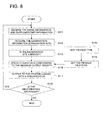
- the following describes the first operation wherein the maximum density setting (density range) of the output film is changed according to the examination information of the subject (information on examination part of an object), with reference to the flowchart shown in Fig. 7.
- the medical image processing apparatus 102 shown in Figs. 5 and 6 receive the image information and image supplementary information including the patient and examination information of that image from the medical image generation apparatus 101 (Step S101).
- Predetermined image processing is applied to the image information as described above, on the one hand, and acquires information on the examination part of an object (e.g. information on the part of an object at the time of radiographing), out of the examination information of the patient from the supplementary information, on the other (Step S102).
- Step S103 the evaluation is made to determine whether the part of an object examined is the breast (mammography) or not (Step S103). If it is the breast, the setting of the maximum output density is changed to 3.6 (Step S104). Further, if the examined part of an object is not a breast but a head, for example, then the setting of the maximum output density is changed to 3.0 (Step S105). This is followed by the step of outputted the processed image information to the printers 106 and 107 (Step S106). When the next printing is carried out (Step S107), the system goes back to the Step S101.
- the main control apparatus 121 rewrites the lookup table (LUT) for conversion between the pixel value and density in the range of the density so that maximum output density will be changed.
- LUT lookup table
- This rewritten LUT is put into the supplementary information and is outputted to the printer together with the image information, whereby the aforementioned change of the setting of the machining output density is implemented.
- the maximum density can be changed by adjusting the amount of laser beam at the time of exposure of the film.
- the maximum output film density can be automatically set to the maximum level (3.6) which is higher than that of other part of an object, depending on the examination information of the patient and information on the examination part of an object. Further, when the examination part is a head, the maximum output film density can be set to 3.0 and can be outputted. As described above, automatic switching of the setting of the maximum output film density reduces user operation error.
- the medical image processing apparatus 102 shown in Figs. 5 and 6 receives the image supplementary information including the patient/examination information from the medical image generation apparatus 101 (Step S111). Predetermined image processing is applied to image information, and the examination part information (e.g. information of the part at the time of radiographing) of the patient examination information is obtained from the supplementary information (Step S112).
- the examination part information e.g. information of the part at the time of radiographing
- the maximum output film density suitable for the image is set according to the examination part information (Step S113). Similarly to the case Fig. 7, this setting can be made by determining whether the examination part of an object is a breast or not, for example.
- the type of the film corresponding to the maximum output density is set (Step S114), and the type of the film in the printers 106 and 107 in Fig. 5 is set (Step S115).
- the film A corresponding to the maximum output density of 3.6 suitable for the case of the examination part of an object being the breast is set.
- This film A being loaded on the printer 106 is also set and is stored in the storage section 141 shown in Fig. 6.
- the film B corresponding to the maximum output density of 3.0 is set.
- this film B being loaded on the printer 107 is also set and is stored in the storage section 141 shown in Fig. 6.
- Step S116 The film A or B corresponding to the maximum output film density having been set as described above is specified (Step S116), and the image information is outputted to the printer 106 or 107 where the specified film is set (Step S117).
- Step S118 the system returns to Step S111.
- the setting of the maximum film density can be changed according to at least one of the obtained examination information and examination part of an object information of the patient, and the image can be outputted to the film specified according to this maximum output film density.
- it can be outputted to the printer 106 or 107 loaded with the film A or B suitable for the image where the setting of the maximum film density has been changed.
- This arrangement provides an image suitable for the diagnosis of a subject. For example, the image where mammographic examination part is the breast can be outputted to the film A on the printer 106 corresponding to the maximum density of 3.6. Further, the image where the examination part is a head can be outputted to the film B on the printer 107 corresponding to the maximum density of 3.0.
- automatic switching of the setting of the maximum film density reduces user operation error.
- Step S117 for example, when one printer 106 has two film trays for accommodating films A and B, the film tray loaded with the film A or B suitable for the image where the setting of the maximum film density is changed is selected and the image is outputted, thereby getting the image suitable for the diagnosis of the subject, in the similar manner.
- the following describes the structure of the medical image processing apparatus 102 shown in Figs. 5 and 6, where the setting of the maximum brightness of the display (monitor) of the image display apparatus 103 shown in Fig. 5 is changed according to the information on the subject.
- Fig. 9 schematically represents the setting of the maximum brightness of the monitor with respect to the examination part of the image, in the medical image processing apparatus 102 shown in Figs. 5 and 6.
- Fig. 10 is a flowchart representing the operation of changing the setting of the maximum brightness of the monitor based on the subject information, in the medical image processing apparatus 102 shown in Figs. 5 and 6.
- the medical image processing apparatus 102 shown in Figs. 5 and 6 it is possible to change the maximum brightness setting of the monitor when the diagnostic image is displayed on the image display apparatus 103, based on the subject information (e.g. part information and specific condition key at the time of radiographing).
- subject information e.g. part information and specific condition key at the time of radiographing.
- the maximum density can be changed on the imager side by adjusting the amount of laser light.
- the maximum density is fixed at the minimum brightness, so this adjustment is made by expanding the entire dynamic range by changing the brightness and the minimum density (maximum brightness).
- the setting of the maximum brightness of the monitor is changed to 700 cd/m 2 .
- the setting of the maximum brightness of the monitor is changed to 420 cd/m 2 .
- the maximum brightness setting can be obtained by changing the JND range (Just-Noticeable Difference, the minimum brightness difference perceptible to human sense) - the maximum brightness on the monitor -, for example, in response to the maximum density of the mammographic image set at 3.6 in the case of a film and the maximum density of the image for other parts set at 3.0.
- JND range Just-Noticeable Difference, the minimum brightness difference perceptible to human sense
- the maximum brightness is set at 700 cd/m 2 for the mammographic image and 420 cd/m 2 for the image of other parts.
- the user can determine the set value by taking glare and other factors into account, if the brightness is 420 cd/m 2 or more. For example, it is possible to select 600 cd/m 2 .
- the medical image processing apparatus 102 shown in Figs. 5 and 6 the following describes the operation of display the image by changing the maximum brightness setting of the monitor is determined, depending on the examination information of the subject (examination part information).
- the medical image processing apparatus 102 shown in Figs. 5 and 6 receives the image information and the image supplementary information including the patient/examination information of the image from the medical image generation apparatus 101 (Step S121).
- predetermined processing is applied to the image information, and the examination part information (e.g. part information at the time of radiographing) out of the patient examination information is acquired from the supplementary information (Step S122).
- Step S123 the evaluation is made to determine whether the part examined is the breast (mammography) or not (Step S123). If it is the breast, the maximum brightness of the monitor of the image display apparatus 103 shown in Fig. 5 is set at 700 cd/m 2 (Step S124). Further, if the examined part is not a breast but a pectoral region, for example, then the maximum brightness of the monitor is set at 420 cd/cm 2 (Step S125).
- Step S126 the image information having been subjected to image processing is outputted to the image display apparatus 103 shown in Fig. 5 (Step S126). If there is the next screen (Step S127), the system goes back to Step S121.
- the maximum brightness in the aforementioned Step S124 or 125 is set by putting the maximum brightness information into the supplementary information and by sending it to the image display apparatus 103 of Fig. 5 as an image file. To put it another way, the command for setting the maximum brightness and the LookUp Table (LUT) for conversion between the pixel value and brightness are sent together with the image information.
- LUT LookUp Table
- the further optimized image display can be ensured for diagnosis corresponding to the examination part, by setting the maximum brightness of the display apparatus at the output destination, based on the examination part of the object. For example, if the image where mammographic examination part is the breast in mammography is to be displayed on the display monitor, the image suitable for the breast can be displayed and observed, by setting the maximum brightness to a higher level and by expanding the dynamic range. Further, this arrangement reduces the user fatigue and allows him or her to observe the diagnostic image by ensuring the feel of making an effective use. Further, this arrangement provides the information on the subject and permits automatic selection of the maximum brightness setting, thereby minimizing both the user operation and operation errors.
- the display monitor has been often used with maximum brightness reduced, according to the prior art. Further, there is a difference in the required dynamic range, depending on the part of the subject. The diagnosis of breasts requires a wider dynamic range than that of other parts.
- the monitor brightness is reduced, hardware capability has not been utilized, in the prior art.
- the hardware capability is fully utilized by using the dynamic range widened by setting the maximum brightness at a higher level. This method ensures easy observation of a mammographic image at the time of image diagnosis.
- the operations of the medical image processing apparatus 102 in the present embodiment are controlled by the main control apparatus 121 of Fig. 6, according to the program stored in the storage section 141, and required information processing is applied.
- the medical image generation apparatus includes, in addition to the CR apparatus where radiographic image is read from the stimulable phosphor panel with the radiographic image information of a patent recorded thereon, a radiographic imaging apparatus using an X-flat panel detector, a CR apparatus (computed radiography), a MRI apparatus (magnetic resonance imaging apparatus), a DR apparatus (digital radiography), a US apparatus (ultrasound) and others. Further, these medical image generation apparatuses can be linked to the network system according to the present invention.
- the medical image generation apparatus, medical network system and the program for the medical image processing apparatus of the present invention provides an image suitable for diagnosis of the examination part of a subject by changing the setting of the output density range and setting of the maximum brightness for display, based on the examination information, when image processing is applied to the received medical image information and the result is sent to other apparatuses.
Landscapes
- Engineering & Computer Science (AREA)
- Multimedia (AREA)
- Signal Processing (AREA)
- Image Processing (AREA)
- Measuring And Recording Apparatus For Diagnosis (AREA)
Applications Claiming Priority (6)
| Application Number | Priority Date | Filing Date | Title |
|---|---|---|---|
| JP2003157872 | 2003-06-03 | ||
| JP2003157872A JP2004363766A (ja) | 2003-06-03 | 2003-06-03 | 医用画像処理装置、医用ネットワークシステム及び医用画像処理装置のためのプログラム |
| JP2003324680 | 2003-09-17 | ||
| JP2003324722A JP2005094331A (ja) | 2003-09-17 | 2003-09-17 | 医用画像システム |
| JP2003324722 | 2003-09-17 | ||
| JP2003324680A JP2005088353A (ja) | 2003-09-17 | 2003-09-17 | 医用画像システム |
Publications (2)
| Publication Number | Publication Date |
|---|---|
| EP1484707A2 true EP1484707A2 (fr) | 2004-12-08 |
| EP1484707A3 EP1484707A3 (fr) | 2006-05-17 |
Family
ID=33162794
Family Applications (1)
| Application Number | Title | Priority Date | Filing Date |
|---|---|---|---|
| EP04253198A Withdrawn EP1484707A3 (fr) | 2003-06-03 | 2004-05-28 | Système d'images médicales et procédé de traitement d'images médicales |
Country Status (2)
| Country | Link |
|---|---|
| US (1) | US20050008262A1 (fr) |
| EP (1) | EP1484707A3 (fr) |
Cited By (1)
| Publication number | Priority date | Publication date | Assignee | Title |
|---|---|---|---|---|
| EP1953660A1 (fr) * | 2006-12-11 | 2008-08-06 | Konica Minolta Medical & Graphic, Inc. | Système radiographique et dispositif de détection d'image à rayonnement |
Families Citing this family (11)
| Publication number | Priority date | Publication date | Assignee | Title |
|---|---|---|---|---|
| US7439996B2 (en) * | 2003-08-25 | 2008-10-21 | Konica Minolta Medical & Graphic, Inc. | Medical image recording system and medical image recording apparatus |
| US7664299B2 (en) * | 2004-04-02 | 2010-02-16 | Kabushiki Kaisha Toshiba | Apparatus that prepares information relating to image data |
| US20060028462A1 (en) * | 2004-08-04 | 2006-02-09 | Konica Minolta Medical & Graphic, Inc. | Calibration method |
| JP2006078652A (ja) * | 2004-09-08 | 2006-03-23 | Fuji Photo Film Co Ltd | 熱現像装置 |
| US20070140536A1 (en) * | 2005-12-19 | 2007-06-21 | Eastman Kodak Company | Medical image processing method and apparatus |
| JP4690204B2 (ja) * | 2006-01-16 | 2011-06-01 | 富士フイルム株式会社 | 画像再生装置およびそのプログラム |
| US20080123929A1 (en) * | 2006-07-03 | 2008-05-29 | Fujifilm Corporation | Apparatus, method and program for image type judgment |
| US20090077556A1 (en) * | 2007-09-19 | 2009-03-19 | Martin Kay Nohr | Image media modifier |
| JP5908248B2 (ja) * | 2010-10-25 | 2016-04-26 | 株式会社東芝 | 医用画像管理システム |
| JP5921511B2 (ja) * | 2013-09-30 | 2016-05-24 | 富士フイルム株式会社 | 放射線画像読取装置、放射線画像読取プログラム、及び放射線画像読取方法 |
| EP3284037A1 (fr) * | 2015-04-16 | 2018-02-21 | United Parcel Service Of America, Inc. | Système d'inspection de cargaison multi-couche amélioré, produit de programme informatique, et son procédé d'utilisation |
Citations (2)
| Publication number | Priority date | Publication date | Assignee | Title |
|---|---|---|---|---|
| JPH06342098A (ja) | 1992-12-16 | 1994-12-13 | E I Du Pont De Nemours & Co | ソリッド・ステート・デバイスを用いたx線イメージ捕獲エレメントおよび方法 |
| JPH0990048A (ja) | 1995-09-28 | 1997-04-04 | Canon Inc | 放射線検出装置 |
Family Cites Families (20)
| Publication number | Priority date | Publication date | Assignee | Title |
|---|---|---|---|---|
| US4918534A (en) * | 1988-04-22 | 1990-04-17 | The University Of Chicago | Optical image processing method and system to perform unsharp masking on images detected by an I.I./TV system |
| SG43270A1 (en) * | 1989-03-15 | 1997-10-17 | Canon Kk | Output apparatus |
| JPH04271564A (ja) * | 1991-02-26 | 1992-09-28 | Fujitsu Ltd | 画像記録装置及び画像記録方法 |
| US5803082A (en) * | 1993-11-09 | 1998-09-08 | Staplevision Inc. | Omnispectramammography |
| EP0679013B1 (fr) * | 1994-04-18 | 1999-06-23 | Canon Kabushiki Kaisha | Appareil, procédé et système de communication de données |
| JPH07323608A (ja) * | 1994-06-01 | 1995-12-12 | Fujitsu Ltd | プリンタ装置 |
| EP0712092A1 (fr) * | 1994-11-10 | 1996-05-15 | Agfa-Gevaert N.V. | Procédé d'amélioration d'images |
| DE69531743D1 (de) * | 1994-11-25 | 2003-10-16 | Sophisview Technologies Ltd | System und verfahren zur diagnose von krankheiten an lebendem gewebe |
| US5774599A (en) * | 1995-03-14 | 1998-06-30 | Eastman Kodak Company | Method for precompensation of digital images for enhanced presentation on digital displays with limited capabilities |
| JP3562019B2 (ja) * | 1995-03-24 | 2004-09-08 | セイコーエプソン株式会社 | インクジェット記録装置 |
| US6941323B1 (en) * | 1999-08-09 | 2005-09-06 | Almen Laboratories, Inc. | System and method for image comparison and retrieval by enhancing, defining, and parameterizing objects in images |
| JP2001092621A (ja) * | 1999-09-21 | 2001-04-06 | Fuji Photo Film Co Ltd | 印刷制御方式 |
| US7221464B2 (en) * | 2000-12-01 | 2007-05-22 | Konica Corporation | Image recording apparatus and test pattern for evaluating recorded image |
| JP2002199197A (ja) * | 2000-12-22 | 2002-07-12 | Murata Mach Ltd | ファクシミリ装置 |
| US7023580B2 (en) * | 2001-04-20 | 2006-04-04 | Agilent Technologies, Inc. | System and method for digital image tone mapping using an adaptive sigmoidal function based on perceptual preference guidelines |
| US7002533B2 (en) * | 2001-08-17 | 2006-02-21 | Michel Sayag | Dual-stage high-contrast electronic image display |
| US7065257B2 (en) * | 2001-09-03 | 2006-06-20 | Kabushiki Kaisha Toyota Chuo Kenkyusho | Image processing method and apparatus |
| CA2412703C (fr) * | 2001-11-23 | 2008-02-05 | Imaging Dynamics Company Ltd. | Equilibrage des aires de densite differente d'une image numerique |
| JP4120209B2 (ja) * | 2001-11-26 | 2008-07-16 | コニカミノルタホールディングス株式会社 | 画像記録装置および医用画像記録装置ならびに医用画像システム |
| EP1461645A4 (fr) * | 2001-12-14 | 2006-09-06 | Digital Optics Internat Corp | Systeme d'eclairage uniforme |
-
2004
- 2004-05-28 EP EP04253198A patent/EP1484707A3/fr not_active Withdrawn
- 2004-05-28 US US10/855,404 patent/US20050008262A1/en not_active Abandoned
Patent Citations (2)
| Publication number | Priority date | Publication date | Assignee | Title |
|---|---|---|---|---|
| JPH06342098A (ja) | 1992-12-16 | 1994-12-13 | E I Du Pont De Nemours & Co | ソリッド・ステート・デバイスを用いたx線イメージ捕獲エレメントおよび方法 |
| JPH0990048A (ja) | 1995-09-28 | 1997-04-04 | Canon Inc | 放射線検出装置 |
Cited By (2)
| Publication number | Priority date | Publication date | Assignee | Title |
|---|---|---|---|---|
| EP1953660A1 (fr) * | 2006-12-11 | 2008-08-06 | Konica Minolta Medical & Graphic, Inc. | Système radiographique et dispositif de détection d'image à rayonnement |
| US7508915B2 (en) | 2006-12-11 | 2009-03-24 | Konica Minolta Medical & Graphic Inc. | Radiographying system and radiation image detecting device |
Also Published As
| Publication number | Publication date |
|---|---|
| EP1484707A3 (fr) | 2006-05-17 |
| US20050008262A1 (en) | 2005-01-13 |
Similar Documents
| Publication | Publication Date | Title |
|---|---|---|
| JP3312975B2 (ja) | 放射線画像ネットワークにおける階調一貫性保証方法及びシステム | |
| US5270530A (en) | Digital radiographic image quality control workstation operable in manual or pass-through modes | |
| US5551428A (en) | Automatic routing to selected destinations of storage phosphor images | |
| US20040186371A1 (en) | Medical image processing apparatus and medical network system | |
| US20090016580A1 (en) | Breast image processing system and breast image processing method | |
| EP1484707A2 (fr) | Système d'images médicales et procédé de traitement d'images médicales | |
| US20040111299A1 (en) | Image information processing apparatus and medical network system | |
| US20040071369A1 (en) | Image management apparatus and medical network system | |
| US20090080609A1 (en) | Digital radiation image imaging system | |
| JP2007286802A (ja) | 医用画像処理装置及びプログラム | |
| EP0599098B1 (fr) | Versions multiples d'une image à substance fluorescente de stockage | |
| US20020131628A1 (en) | Medical image generating apparatus, medical image processing apparatus and medical network system | |
| US7171612B2 (en) | Medical image processing apparatus and medical network system | |
| US20020131627A1 (en) | Medical image generating apparatus, medical image processing apparatus and medical network system | |
| US6381348B2 (en) | Network system for medical images | |
| US7439996B2 (en) | Medical image recording system and medical image recording apparatus | |
| JP2004290225A (ja) | 医用画像処理装置、医用ネットワークシステム及び医用画像処理装置のためのプログラム | |
| US20020133313A1 (en) | Medical image generating apparatus, medical image processing apparatus and medical network system | |
| JP2004073340A (ja) | 医用画像処理装置、医用ネットワークシステム及び医用画像処理装置のためのプログラム | |
| JP2004073341A (ja) | 医用画像処理装置、医用ネットワークシステム及び医用画像処理装置のためのプログラム | |
| JP3965684B2 (ja) | 医用画像処理装置、医用ネットワークシステム及び医用画像処理装置のためのプログラム | |
| JP2005088353A (ja) | 医用画像システム | |
| US20050046879A1 (en) | Medical image recorder | |
| JP2005094331A (ja) | 医用画像システム | |
| JP2004363766A (ja) | 医用画像処理装置、医用ネットワークシステム及び医用画像処理装置のためのプログラム |
Legal Events
| Date | Code | Title | Description |
|---|---|---|---|
| PUAI | Public reference made under article 153(3) epc to a published international application that has entered the european phase |
Free format text: ORIGINAL CODE: 0009012 |
|
| AK | Designated contracting states |
Kind code of ref document: A2 Designated state(s): AT BE BG CH CY CZ DE DK EE ES FI FR GB GR HU IE IT LI LU MC NL PL PT RO SE SI SK TR |
|
| AX | Request for extension of the european patent |
Extension state: AL HR LT LV MK |
|
| RIN1 | Information on inventor provided before grant (corrected) |
Inventor name: TODA, HARUYUKI,KONICA MINOLTA Inventor name: NAKAZAWA, MASAYUKI,KONICA MINOLTA Inventor name: UMEKI, MAMORU,KONICA MINOLTA Inventor name: KOMIYA, YUJI,KONICA MINOLTA |
|
| PUAL | Search report despatched |
Free format text: ORIGINAL CODE: 0009013 |
|
| AK | Designated contracting states |
Kind code of ref document: A3 Designated state(s): AT BE BG CH CY CZ DE DK EE ES FI FR GB GR HU IE IT LI LU MC NL PL PT RO SE SI SK TR |
|
| AX | Request for extension of the european patent |
Extension state: AL HR LT LV MK |
|
| 17P | Request for examination filed |
Effective date: 20061024 |
|
| 17Q | First examination report despatched |
Effective date: 20061206 |
|
| AKX | Designation fees paid |
Designated state(s): DE FR GB |
|
| RAP1 | Party data changed (applicant data changed or rights of an application transferred) |
Owner name: KONICA MINOLTA MEDICAL & GRAPHIC, INC. |
|
| STAA | Information on the status of an ep patent application or granted ep patent |
Free format text: STATUS: THE APPLICATION IS DEEMED TO BE WITHDRAWN |
|
| 18D | Application deemed to be withdrawn |
Effective date: 20101201 |