EP1484509B1 - Unité soufflante double - Google Patents
Unité soufflante double Download PDFInfo
- Publication number
- EP1484509B1 EP1484509B1 EP04010404A EP04010404A EP1484509B1 EP 1484509 B1 EP1484509 B1 EP 1484509B1 EP 04010404 A EP04010404 A EP 04010404A EP 04010404 A EP04010404 A EP 04010404A EP 1484509 B1 EP1484509 B1 EP 1484509B1
- Authority
- EP
- European Patent Office
- Prior art keywords
- fan
- dual
- support element
- arrangement according
- housing
- Prior art date
- Legal status (The legal status is an assumption and is not a legal conclusion. Google has not performed a legal analysis and makes no representation as to the accuracy of the status listed.)
- Expired - Lifetime
Links
- 230000009977 dual effect Effects 0.000 title description 2
- 230000002093 peripheral effect Effects 0.000 claims description 3
- 230000001419 dependent effect Effects 0.000 description 2
- 229910052782 aluminium Inorganic materials 0.000 description 1
- XAGFODPZIPBFFR-UHFFFAOYSA-N aluminium Chemical compound [Al] XAGFODPZIPBFFR-UHFFFAOYSA-N 0.000 description 1
- 230000002146 bilateral effect Effects 0.000 description 1
- 239000000969 carrier Substances 0.000 description 1
- 150000001875 compounds Chemical class 0.000 description 1
- 238000010276 construction Methods 0.000 description 1
- 230000000694 effects Effects 0.000 description 1
- 238000009434 installation Methods 0.000 description 1
- 229910052751 metal Inorganic materials 0.000 description 1
- 239000002184 metal Substances 0.000 description 1
- 125000006850 spacer group Chemical group 0.000 description 1
- 239000000725 suspension Substances 0.000 description 1
Images


Classifications
-
- F—MECHANICAL ENGINEERING; LIGHTING; HEATING; WEAPONS; BLASTING
- F04—POSITIVE - DISPLACEMENT MACHINES FOR LIQUIDS; PUMPS FOR LIQUIDS OR ELASTIC FLUIDS
- F04D—NON-POSITIVE-DISPLACEMENT PUMPS
- F04D25/00—Pumping installations or systems
- F04D25/16—Combinations of two or more pumps ; Producing two or more separate gas flows
- F04D25/166—Combinations of two or more pumps ; Producing two or more separate gas flows using fans
-
- F—MECHANICAL ENGINEERING; LIGHTING; HEATING; WEAPONS; BLASTING
- F04—POSITIVE - DISPLACEMENT MACHINES FOR LIQUIDS; PUMPS FOR LIQUIDS OR ELASTIC FLUIDS
- F04D—NON-POSITIVE-DISPLACEMENT PUMPS
- F04D29/00—Details, component parts, or accessories
- F04D29/40—Casings; Connections of working fluid
- F04D29/42—Casings; Connections of working fluid for radial or helico-centrifugal pumps
- F04D29/4206—Casings; Connections of working fluid for radial or helico-centrifugal pumps especially adapted for elastic fluid pumps
- F04D29/4226—Fan casings
- F04D29/424—Double entry casings
Definitions
- the present invention relates to a double-blower arrangement with two of a common electric motor co-axial driven radial blowers, each having two axial, opposite air intake and a radial or tangential Beerausblasö réelle, consisting of one of the electric motor and two supported on both sides motor shaft ends Laufrad wheels fan assembly and a housing assembly housing the fan assembly.
- the housing assembly consists of a two-part overall housing with a horizontal, extending in the axial direction of the division plane, so that a lower housing shell and an upper housing shell are formed. These housing parts each have a central engine compartment and two-sided Lüfterradschreib.
- the fan assembly with motor and two fan wheels is inserted into the lower housing part and then enclosed by placing the upper housing part. Due to the overall housing, the individual parts are only suitable for a special design of the blower, ie different blower versions require specially designed parts. This design is only feasible for small units, since larger units would incur very high tooling costs.
- Such or similar prior art describe, for example, the documents DE 32 34 006 A1 and US 3,780,411 , where, for example, the DE 32 34 006 A1 describes a blower arrangement formed from two individual radial blowers, wherein the two wheels sit on two ends of a continuous shaft of a common electric motor.
- the motor is attached via a strap on a housing base (console), and both blowers and their housing parts are also connected via spacers to the housing base.
- the present invention has for its object to provide a double blower arrangement of the type described above, generic type, which also without a z. B. user-specific console or the like mounting part a self-supporting function as a whole assembly, but also also ensures a high execution variability to the effect that in a simple and cost-effective manner different blower designs can be realized.
- the housing assembly consists of two separate fan housings for receiving one of the two wheels and a separate support member for supporting the fan assembly in the region of the electric motor, wherein the two fan housing via the support member with each other and with the fan assembly are connected to a preassembled overall assembly.
- the carrier element according to the invention advantageously fulfills a dual function in that on the one hand it serves for supportingly receiving the fan assembly consisting of the electric motor and two impellers and on the other hand also connects the two fan housings to one another.
- the double-blower arrangement according to the invention thus consists of individual components (modules), whereby advantageously different designs can be realized very simply, quickly and cost-effectively in "sandwich assembly" in the manner of a modular principle.
- the components or modules are combined without additional mounting means to form a complete assembly, the compounds need only be so strong and stable that this for a safer transport and a necessary handling during assembly is sufficient (self-carrying function).
- the final fatigue life of the overall assembly can then be achieved by the user by mounting the blower housing parts to a console.
- the fan housing in each case have a mounting flange enclosing the air outlet opening, with which they can be fastened in particular via screw fasteners to a console.
- the fan assembly with motor and Laufrädem is then suspended virtually on the support element according to the invention on or between the two housings.
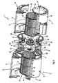
- a double-blower arrangement 1 consists of two radial fans 2, 3 sucking on both sides, which are driven coaxially by a common electric motor 4 arranged approximately centrally therebetween.
- Each radial fan 2, 3 has two axial, opposite air intake openings 6 and a radial or tangential Beerausblasö réelle 8.
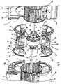
- the electric motor 4 has a motor shaft 10, which protrudes on both sides from the motor 4, and together with two rotor wheels 12 held at the ends of the motor shaft 10 forms a fan assembly 14 Fig. 2 and 5 clearly visible.
- the fan assembly 1 further comprises a housing assembly 16 for receiving the fan assembly 14.
- this housing assembly 16 consists of two separate, preferably similar blower housings (spiral housings) 18 for receiving one of the two wheels 12 and a separate support member 20 for storage of the fan assembly 14 in the region of the electric motor 4 Fig. 1 . 4 and 6 the two fan housing 18 via the support member 20 with each other and because of the inclusion of the fan assembly 14 also connected to this to a preassembled overall assembly.
- blower housings spiral housings
- the invention is provided in a preferred embodiment that the support member 20 is connected to each of the two fan housing 18 via a respective air intake opening 6 enclosing positive connection in the manner of a groove / spring connection with radial engagement.
- each blower housing 18 is divided into two housing parts 18a and 18b which divide diametrically the air intake openings 6.
- the support member 20 has two opposing annular connecting portions 22 such that the housing parts 18a, b each Blower housing 18 can be joined together under positive inclusion of the respective connecting portion 22 of the support member 20.
- each form-locking groove / spring connection on the one hand consists of a radial groove 24 of the respective blower housing 18, which encloses the respective air intake opening 6, and on the other hand of a radial web 26 of the connecting portion 22 of the support element 20.
- a radial groove 24 of the respective blower housing 18 which encloses the respective air intake opening 6, and on the other hand of a radial web 26 of the connecting portion 22 of the support element 20.
- additional radial projections 28 of the radial web 26 engage in corresponding radial recesses 30 within the respective radial groove 24 (see in particular Fig. 3 ).
- another, z. B. reverse positive engagement is possible, for. B. a radial web in the region of the respective suction port 6 and a corresponding groove on the connecting portion 22 of the support element 20th
- each fan housing 18 is divided into the housing parts 18a, b, that the shipsausblasö réelle 8 is also divided.
- the illustrated arrangement in space is thus about a “horizontal” division. But it is also any other division, for example, “vertically” possible.
- annular connecting sections 22 of the carrier element 20 each have a peripheral edge 32 curved inwards in the direction of the suction due to their arrangement in the peripheral region of the respective air intake opening 6; see in particular Fig. 3 ,
- the two fan housing 18 may be identical.
- each blower housing 18 in the region of its facing away from the electric motor 4, the outside air intake 6 have a nozzle-like inlet ring 34, which - then analogously to the described connection of the blower housing 18 with the support member 20 - is held via a corresponding positive connection within the suction port 6.
- the carrier element 20 is subdivided into two carrier parts 20a and 20b, in particular identically designed carriers, which are detachably connected to one another while the electric motor 4 is received connected or connectable. This allows a particularly simple assembly of the items, which will be explained in more detail below.
- the carrier element 20 has in its axially approximately central region on a substantially annular, the region of the electric motor 4 enclosing support portion 36 which is connected to the bilateral Kunststoffsabschntten 22 about approximately axial or axially parallel and / or obliquely inclined to the axis extending connecting struts 38 ,
- the overlapping recording of the fan assembly 14 differs in the illustrated embodiments. It is common, however, that the fan assembly 14 is advantageously mounted in the carrier element 20 via vibration-isolating, elastic bearing elements 40 or vibration-isolating elements 50.
- the carrier element 20 in the respective lying axially on both sides of the electric motor 4 areas each have a bearing portion 42 for receiving the respective bearing element 40.
- the bearing sections 42 are connected to the connecting struts 38, for example via radial struts 44.
- the electric motor 4 is an external rotor motor, wherein a free rotation of the external rotor is ensured by a radial gap to the carrier portion 36.
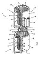
- FIG. 4 and 5 In the execution according to Fig. 4 and 5 is attached to a stator bushing of the electric motor 4, an additional support member 46 which engages over the electric motor 4 radially and axially with spoke-like bearing arms 48.
- the support member 20 receives the motor 4 with its central support portion 36, 46 between the support portion 36 and the bearing arms 48 of the support member elastic vibration isolating elements 50 are arranged, which sit expediently in corresponding retaining receptacles of support portion 36 and bearing arms 48.
- This version is basically suitable for both external and internal rotor motors.
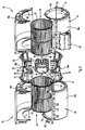
- Fig. 6 and 7 it is an internal rotor motor which can be received directly in the region of its outer periphery of the support portion 36 of the support member 20. But it can also be provided on storage by the shaft ends 10 accessed, elastic bearing elements.
- the housing parts 18a, 18b of the blower housing 18 and / or the carrier parts 20a, 20b of the carrier element 20 are releasably assembled substantially without screws, in particular via clip elements 52 or the like.
- clip elements 52 are particularly in Fig. 3 and 5 exemplified.
- suitable interlocking elements may be provided for mutual engagement, which facilitates a correct position, accurately positioned joining of the items.
- the fan housing 18 each have a Heilausblasö réelle 8 enclosing, in the illustrated embodiments approximately rectangular mounting flange 54 for attachment, in particular screw fastening, on a console, not shown.
- the carrier element 20 or its carrier parts 20a, 20b is preferably made of plastic, however, a design made of metal, in particular aluminum die-cast, is also possible. The same applies to the blower housing 18 and the housing parts 18a, 18b.
- the support member 20 in a direction corresponding to the axial direction is divided into the support members 20a, 20b.
- the previously preassembled fan assembly 14 can be stored in the carrier element 20, in that only the carrier parts 20a, 20b, including the region of the electric motor 4, need to be joined together.
- the carrier element 20 thus connected to the fan assembly 14 is then initially inserted with the connecting portions 22 in the lower housing parts 18a in the region of the air intake openings. Accordingly, on the opposite Pages each used an inlet ring 34. It then only need the upper housing parts 18b placed and fixed.
- the carrier element 20 is divided perpendicular to the axis. Therefore, in this case first the support members 20a and 20b must be placed on the ends of the shaft 10 for receiving the electric motor 4, and only then can the wheels (in Fig. 6 and 7 not shown) are mounted on the shaft ends 10. The connection with the housing parts 18 then takes place analogously to the above description.
- a terminal housing 56 For electrical connection of the electric motor 4 can according to Fig. 1 to 5 outside of one of the fan housing 18, a terminal housing 56 may be arranged.
- a connector part 58 is used to connect an extemen connection cable (not shown).
- a cable 60 extends to the motor 4th
Landscapes
- Engineering & Computer Science (AREA)
- Mechanical Engineering (AREA)
- General Engineering & Computer Science (AREA)
- Structures Of Non-Positive Displacement Pumps (AREA)
Claims (17)
- Unité soufflante double (1) comprenant deux souffleries radiales (2, 3) entraînées coaxialement par un moteur électrique (4) commun qui présentent chacune deux ouvertures d'aspiration d'air (6) axiales opposées et une ouverture de rejet d'air (8) radiale respectivement tangentielle, cette unité se composant d'un bloc de ventilateurs (14) formé du moteur électrique (4) et de deux rotors (12) maintenus sur des extrémités bilatérales de l'arbre du moteur (10) et d'un bloc de carters (16) recevant le bloc de ventilateurs (14), le bloc de carters (16) étant composé de deux carters de soufflerie (18) séparés pour recevoir chacun l'un des deux rotors (12) ainsi que d'un élément de support (20) séparé pour recevoir de manière à l'appuyer le bloc de ventilateurs (14) au niveau du moteur électrique (4), moyennant quoi les deux carters de soufflerie (18) sont reliés entre eux par l'élément de support (20) et sont reliés avec le bloc de ventilateurs (14) en un bloc complet prémonté,
caractérisée en ce que chaque carter de soufflerie (18) peut être fixé sur une console de telle sorte que le bloc de ventilateurs (14) est suspendu avec le moteur électrique (4) et les rotors (12) par l'élément de support (20) reliant les carters de soufflerie (18) aux deux carters de soufflerie (18) fixés ou à fixer sur la console. - Unité soufflante double selon la revendication 1,
caractérisée en ce que les carters de soufflerie (18) présentent chacun une bride de montage (54) entourant l'ouverture de rejet d'air(8) pour la fixation sur la console. - Unité soufflante double selon la revendication 1 ou 2,
caractérisée en ce que l'élément de support (20) est relié à chacun des deux carters de soufflerie (18) par une liaison de forme entourant l'ouverture d'aspiration d'air (6) respective selon le type d'un assemblage rainure/languette avec saillie radiale. - Unité soufflante double selon l'une des revendications 1 à 3,
caractérisée en ce que chaque carter de soufflerie (18) est divisé en deux parties de carter (18a, 18b) séparant les ouvertures d'aspiration d'air (6) et l'élément de support (20) présente deux sections de liaison (22) annulaires de telle sorte que les parties de carter (18a, 18b) de chaque carter de soufflerie (18) sont réunies ou peuvent être réunies par insertion par liaison de forme de chaque section de liaison (22) de l'élément de support (20). - Unité soufflante double selon la revendication 3 ou 4,
caractérisée en ce que les parties de carter (18a, 18b) présentent au niveau d'au moins une de leurs ouvertures d'aspiration d'air (6) une dernière rainure radiale (24) entourante pour recevoir une traverse radiale correspondante (26) de la section de liaison (22) de l'élément de support (20). - Unité soufflante double selon la revendication 4 ou 5,
caractérisée en ce que les parties de carter (18a, 18b) de chaque carter de soufflerie (18) partagent également l'ouverture de rejet d'air (8). - Unité soufflante double selon l'une des revendications 4 à 6,
caractérisée en ce que les sections de liaison (22) annulaires de l'élément de support (20) présentent respectivement une bordure périphérique (2) en forme de douille bombée dans le sens d'aspiration. - Unité soufflante double selon l'une des revendications 1 à 7,
caractérisée en ce que les deux carters de soufflerie (18) sont formés à l'identique. - Unité soufflante double selon la revendication 8,
caractérisée en ce que chaque carter de soufflerie (18) présente, au niveau de son ouverture d'aspiration d'air (6, 7) extérieure opposée au moteur électrique (4), une bague d'admission (34) en forme de douille qui est maintenue par une liaison de forme de manière similaire à la liaison du carter de soufflerie (18) avec l'élément de support (20). - Unité soufflante double selon l'une des revendications 1 à 9,
caractérisée en ce que l'élément de support (20) est subdivisé en deux parties de support (20a, 20b) particulièrement identiques, qui sont reliées respectivement peuvent être reliées entre elles par une réception d'appui du moteur électrique (4). - Unité soufflante double selon l'une des revendications 1 à 10,
caractérisée en ce que le bloc de ventilateurs (14) est disposé dans l'élément de support (20) par des éléments d'appui (40) découplant les oscillations respectivement isolant des oscillations. - Unité soufflante double selon l'une des revendications 4 à 11,
caractérisée en ce que l'élément de support (20) présente dans sa zone environ centrale et axiale une section de support (36) entourant la zone du moteur électrique (4) qui est reliée aux sections de liaison (22) par des traverses de liaison (38). - Unité soufflante double selon l'une des revendications 1 à 12,
caractérisée en ce que l'élément de support (20), dans des zones axiales latérales du moteur électrique (4), présente respectivement une section d'appui (42) pour recevoir un élément d'appui (40). - Unité soufflante double selon l'une des revendications 1 à 12,
caractérisée en ce qu'un élément de support (46) est fixé sur au moins une douille de stator du moteur électrique (4) qui recouvre le moteur électrique (4) radialement et axialement par des bras d'appui (48) en forme de croisillon, des éléments (50) élastiques isolants contre les oscillations étant disposés entre l'élément de support (20) et les bras d'appui (48). - Unité soufflante double selon l'une des revendications 1 à 14,
caractérisée en ce que le moteur électrique (4) est formé comme un moteur à rotor externe. - Unité soufflante double selon l'une des revendications 1 à 14,
caractérisée en ce que le moteur électrique (4) est un moteur à rotor interne. - Unité soufflante double selon l'une des revendications 4 à 16,
caractérisée en ce que les parties de carter (18a, 18b) des carters de soufflerie (18) et/ou les parties de support (20a, 20b) de l'élément de support (20) sont réunies de manière séparable essentiellement sans vissage, particulièrement par des éléments de fixation (20) ou similaires.
Applications Claiming Priority (2)
| Application Number | Priority Date | Filing Date | Title |
|---|---|---|---|
| DE20308886U DE20308886U1 (de) | 2003-06-05 | 2003-06-05 | Doppel-Gebläseanordnung |
| DE20308886U | 2003-06-05 |
Publications (2)
| Publication Number | Publication Date |
|---|---|
| EP1484509A1 EP1484509A1 (fr) | 2004-12-08 |
| EP1484509B1 true EP1484509B1 (fr) | 2008-03-12 |
Family
ID=33154659
Family Applications (1)
| Application Number | Title | Priority Date | Filing Date |
|---|---|---|---|
| EP04010404A Expired - Lifetime EP1484509B1 (fr) | 2003-06-05 | 2004-05-03 | Unité soufflante double |
Country Status (4)
| Country | Link |
|---|---|
| EP (1) | EP1484509B1 (fr) |
| AT (1) | ATE389116T1 (fr) |
| DE (2) | DE20308886U1 (fr) |
| ES (1) | ES2301894T3 (fr) |
Cited By (8)
| Publication number | Priority date | Publication date | Assignee | Title |
|---|---|---|---|---|
| EP2653729A1 (fr) | 2012-04-20 | 2013-10-23 | ebm-papst Mulfingen GmbH & Co. KG | Ventilateur radial avec un carter auxiliaire protégé électromagnétiquement pour l'électronique de contrôle |
| US8839815B2 (en) | 2011-12-15 | 2014-09-23 | Honeywell International Inc. | Gas valve with electronic cycle counter |
| US8899264B2 (en) | 2011-12-15 | 2014-12-02 | Honeywell International Inc. | Gas valve with electronic proof of closure system |
| US8905063B2 (en) | 2011-12-15 | 2014-12-09 | Honeywell International Inc. | Gas valve with fuel rate monitor |
| US8947242B2 (en) | 2011-12-15 | 2015-02-03 | Honeywell International Inc. | Gas valve with valve leakage test |
| US9074770B2 (en) | 2011-12-15 | 2015-07-07 | Honeywell International Inc. | Gas valve with electronic valve proving system |
| US9234661B2 (en) | 2012-09-15 | 2016-01-12 | Honeywell International Inc. | Burner control system |
| US9557059B2 (en) | 2011-12-15 | 2017-01-31 | Honeywell International Inc | Gas valve with communication link |
Families Citing this family (19)
| Publication number | Priority date | Publication date | Assignee | Title |
|---|---|---|---|---|
| ITTO20050405A1 (it) * | 2005-06-10 | 2006-12-11 | Denso Thermal Systems Spa | Gruppo di ventilazione a doppia ventola per veicoli |
| ITBO20070382A1 (it) * | 2007-05-31 | 2008-12-01 | Spal Automotive Srl | Elettroventilatore |
| EP2236838B1 (fr) * | 2009-03-25 | 2016-09-21 | ebm-papst Mulfingen GmbH & Co. KG | Ventilateur radial |
| CN102865239A (zh) * | 2011-07-04 | 2013-01-09 | 陈平亮 | 一种大型空间使用的四周全方位出风的吹风机 |
| US9851103B2 (en) | 2011-12-15 | 2017-12-26 | Honeywell International Inc. | Gas valve with overpressure diagnostics |
| US9995486B2 (en) | 2011-12-15 | 2018-06-12 | Honeywell International Inc. | Gas valve with high/low gas pressure detection |
| US9835265B2 (en) | 2011-12-15 | 2017-12-05 | Honeywell International Inc. | Valve with actuator diagnostics |
| US9846440B2 (en) | 2011-12-15 | 2017-12-19 | Honeywell International Inc. | Valve controller configured to estimate fuel comsumption |
| US10422531B2 (en) | 2012-09-15 | 2019-09-24 | Honeywell International Inc. | System and approach for controlling a combustion chamber |
| DE102013204144A1 (de) * | 2013-03-11 | 2014-09-11 | BSH Bosch und Siemens Hausgeräte GmbH | Gehäuse für ein Radialgebläse einer Dunstabzugshaube |
| EP2868970B1 (fr) | 2013-10-29 | 2020-04-22 | Honeywell Technologies Sarl | Dispositif de régulation |
| US10024439B2 (en) | 2013-12-16 | 2018-07-17 | Honeywell International Inc. | Valve over-travel mechanism |
| US9841122B2 (en) | 2014-09-09 | 2017-12-12 | Honeywell International Inc. | Gas valve with electronic valve proving system |
| US9645584B2 (en) | 2014-09-17 | 2017-05-09 | Honeywell International Inc. | Gas valve with electronic health monitoring |
| US10503181B2 (en) | 2016-01-13 | 2019-12-10 | Honeywell International Inc. | Pressure regulator |
| US10564062B2 (en) | 2016-10-19 | 2020-02-18 | Honeywell International Inc. | Human-machine interface for gas valve |
| KR20180122258A (ko) * | 2017-05-02 | 2018-11-12 | 엘지전자 주식회사 | 국소 배기 장치 및 이에 구비된 송풍장치 |
| US11073281B2 (en) | 2017-12-29 | 2021-07-27 | Honeywell International Inc. | Closed-loop programming and control of a combustion appliance |
| US10697815B2 (en) | 2018-06-09 | 2020-06-30 | Honeywell International Inc. | System and methods for mitigating condensation in a sensor module |
Family Cites Families (5)
| Publication number | Priority date | Publication date | Assignee | Title |
|---|---|---|---|---|
| CH381798A (de) * | 1960-06-17 | 1964-09-15 | Wirz Paul | Ventilatoraggregat |
| US3780411A (en) * | 1972-10-19 | 1973-12-25 | Case Co J I | Method of making blower housing assembly |
| US4165953A (en) * | 1977-10-17 | 1979-08-28 | Deere & Company | Blower assembly |
| DE3234006A1 (de) * | 1982-09-14 | 1984-03-22 | Robert Bosch Gmbh, 7000 Stuttgart | Geblaese |
| US5403163A (en) * | 1990-08-20 | 1995-04-04 | Molded Products Company | Motor mount for blower housing |
-
2003
- 2003-06-05 DE DE20308886U patent/DE20308886U1/de not_active Expired - Lifetime
-
2004
- 2004-05-03 AT AT04010404T patent/ATE389116T1/de not_active IP Right Cessation
- 2004-05-03 DE DE502004006459T patent/DE502004006459D1/de not_active Expired - Lifetime
- 2004-05-03 ES ES04010404T patent/ES2301894T3/es not_active Expired - Lifetime
- 2004-05-03 EP EP04010404A patent/EP1484509B1/fr not_active Expired - Lifetime
Cited By (8)
| Publication number | Priority date | Publication date | Assignee | Title |
|---|---|---|---|---|
| US8839815B2 (en) | 2011-12-15 | 2014-09-23 | Honeywell International Inc. | Gas valve with electronic cycle counter |
| US8899264B2 (en) | 2011-12-15 | 2014-12-02 | Honeywell International Inc. | Gas valve with electronic proof of closure system |
| US8905063B2 (en) | 2011-12-15 | 2014-12-09 | Honeywell International Inc. | Gas valve with fuel rate monitor |
| US8947242B2 (en) | 2011-12-15 | 2015-02-03 | Honeywell International Inc. | Gas valve with valve leakage test |
| US9074770B2 (en) | 2011-12-15 | 2015-07-07 | Honeywell International Inc. | Gas valve with electronic valve proving system |
| US9557059B2 (en) | 2011-12-15 | 2017-01-31 | Honeywell International Inc | Gas valve with communication link |
| EP2653729A1 (fr) | 2012-04-20 | 2013-10-23 | ebm-papst Mulfingen GmbH & Co. KG | Ventilateur radial avec un carter auxiliaire protégé électromagnétiquement pour l'électronique de contrôle |
| US9234661B2 (en) | 2012-09-15 | 2016-01-12 | Honeywell International Inc. | Burner control system |
Also Published As
| Publication number | Publication date |
|---|---|
| DE502004006459D1 (de) | 2008-04-24 |
| ATE389116T1 (de) | 2008-03-15 |
| DE20308886U1 (de) | 2004-10-14 |
| ES2301894T3 (es) | 2008-07-01 |
| EP1484509A1 (fr) | 2004-12-08 |
Similar Documents
| Publication | Publication Date | Title |
|---|---|---|
| EP1484509B1 (fr) | Unité soufflante double | |
| DE19936644B4 (de) | Elektrische Luftpumpe für Kraftfahrzeuge | |
| EP1094224B1 (fr) | Soufflante radiale | |
| EP2242930B1 (fr) | Ventilateur compact | |
| EP0985829B1 (fr) | Boítier pour soufflante radial | |
| DE19850461A1 (de) | Gebläselaufrad, sowie Gebläse hiermit | |
| DE69802989T2 (de) | Trägerstruktur für Heizkörper und Befestigung an der Karosserie eines Kraftfahrzeuges | |
| EP3101350B1 (fr) | Unite de ventilateur pour hotte aspirante et hotte aspirante | |
| EP1664539B1 (fr) | Pompe a roue a denture interieure comportant des ouvertures renforcees | |
| DE19636820C2 (de) | Vorrichtung zur Aufnahme einer Motorlagerung eines Verbrennungsmotors | |
| DE4222264C2 (de) | Kühlvorrichtung für ein Kraftfahrzeug | |
| EP0338549B1 (fr) | Appareil de protection pour un ventilateur d'un moteur à combustion | |
| WO1989007717A1 (fr) | Ventilateur axial | |
| DE602004000548T2 (de) | Antriebslaterne in Blockpumpen und Schutzverkleidung fur diese Laterne | |
| DE19946849B4 (de) | Spaltrohrmotorpumpe | |
| DE2001395B2 (de) | Seitenkanalgeblaese | |
| EP0826262A1 (fr) | Moteur electrique silencieux, notamment moteur electrique a collecteur | |
| DE2724829C2 (de) | Querstrom-Radiallüfter-Einheit | |
| EP0855782A1 (fr) | Moteur électrique silencieux, notamment pour l'entraínement d'un ventilateur d'automobile | |
| DE602004011103T2 (de) | Motorlagervorrichtung | |
| DE4203689C2 (de) | Elektromotor mit schraubenlosem Rahmenaufbau | |
| DE20318344U1 (de) | Motorgehäuse für einen Elektromotor | |
| DE3439539A1 (de) | Ventilator | |
| DE9418283U1 (de) | Vorrichtung zur Halterung eines Elektromotors | |
| DE102008052313A1 (de) | Elektromotor |
Legal Events
| Date | Code | Title | Description |
|---|---|---|---|
| PUAI | Public reference made under article 153(3) epc to a published international application that has entered the european phase |
Free format text: ORIGINAL CODE: 0009012 |
|
| AK | Designated contracting states |
Kind code of ref document: A1 Designated state(s): AT BE BG CH CY CZ DE DK EE ES FI FR GB GR HU IE IT LI LU MC NL PL PT RO SE SI SK TR |
|
| AX | Request for extension of the european patent |
Extension state: AL HR LT LV MK |
|
| 17P | Request for examination filed |
Effective date: 20041026 |
|
| AKX | Designation fees paid |
Designated state(s): AT BE BG CH CY CZ DE DK EE ES FI FR GB GR HU IE IT LI LU MC NL PL PT RO SE SI SK TR |
|
| 17Q | First examination report despatched |
Effective date: 20060920 |
|
| GRAP | Despatch of communication of intention to grant a patent |
Free format text: ORIGINAL CODE: EPIDOSNIGR1 |
|
| GRAS | Grant fee paid |
Free format text: ORIGINAL CODE: EPIDOSNIGR3 |
|
| GRAA | (expected) grant |
Free format text: ORIGINAL CODE: 0009210 |
|
| AK | Designated contracting states |
Kind code of ref document: B1 Designated state(s): AT BE BG CH CY CZ DE DK EE ES FI FR GB GR HU IE IT LI LU MC NL PL PT RO SE SI SK TR |
|
| REG | Reference to a national code |
Ref country code: GB Ref legal event code: FG4D Free format text: NOT ENGLISH |
|
| REG | Reference to a national code |
Ref country code: CH Ref legal event code: EP |
|
| REG | Reference to a national code |
Ref country code: IE Ref legal event code: FG4D Free format text: LANGUAGE OF EP DOCUMENT: GERMAN |
|
| REF | Corresponds to: |
Ref document number: 502004006459 Country of ref document: DE Date of ref document: 20080424 Kind code of ref document: P |
|
| REG | Reference to a national code |
Ref country code: ES Ref legal event code: FG2A Ref document number: 2301894 Country of ref document: ES Kind code of ref document: T3 |
|
| PG25 | Lapsed in a contracting state [announced via postgrant information from national office to epo] |
Ref country code: FI Free format text: LAPSE BECAUSE OF FAILURE TO SUBMIT A TRANSLATION OF THE DESCRIPTION OR TO PAY THE FEE WITHIN THE PRESCRIBED TIME-LIMIT Effective date: 20080312 |
|
| ET | Fr: translation filed | ||
| NLV1 | Nl: lapsed or annulled due to failure to fulfill the requirements of art. 29p and 29m of the patents act | ||
| PG25 | Lapsed in a contracting state [announced via postgrant information from national office to epo] |
Ref country code: PL Free format text: LAPSE BECAUSE OF FAILURE TO SUBMIT A TRANSLATION OF THE DESCRIPTION OR TO PAY THE FEE WITHIN THE PRESCRIBED TIME-LIMIT Effective date: 20080312 Ref country code: SI Free format text: LAPSE BECAUSE OF FAILURE TO SUBMIT A TRANSLATION OF THE DESCRIPTION OR TO PAY THE FEE WITHIN THE PRESCRIBED TIME-LIMIT Effective date: 20080312 |
|
| REG | Reference to a national code |
Ref country code: IE Ref legal event code: FD4D |
|
| PG25 | Lapsed in a contracting state [announced via postgrant information from national office to epo] |
Ref country code: SK Free format text: LAPSE BECAUSE OF FAILURE TO SUBMIT A TRANSLATION OF THE DESCRIPTION OR TO PAY THE FEE WITHIN THE PRESCRIBED TIME-LIMIT Effective date: 20080312 Ref country code: PT Free format text: LAPSE BECAUSE OF FAILURE TO SUBMIT A TRANSLATION OF THE DESCRIPTION OR TO PAY THE FEE WITHIN THE PRESCRIBED TIME-LIMIT Effective date: 20080818 Ref country code: SE Free format text: LAPSE BECAUSE OF FAILURE TO SUBMIT A TRANSLATION OF THE DESCRIPTION OR TO PAY THE FEE WITHIN THE PRESCRIBED TIME-LIMIT Effective date: 20080612 |
|
| PG25 | Lapsed in a contracting state [announced via postgrant information from national office to epo] |
Ref country code: NL Free format text: LAPSE BECAUSE OF FAILURE TO SUBMIT A TRANSLATION OF THE DESCRIPTION OR TO PAY THE FEE WITHIN THE PRESCRIBED TIME-LIMIT Effective date: 20080312 Ref country code: RO Free format text: LAPSE BECAUSE OF FAILURE TO SUBMIT A TRANSLATION OF THE DESCRIPTION OR TO PAY THE FEE WITHIN THE PRESCRIBED TIME-LIMIT Effective date: 20080312 |
|
| BERE | Be: lapsed |
Owner name: EBM-PAPST MULFINGEN G.M.B.H. & CO.KG Effective date: 20080531 |
|
| PG25 | Lapsed in a contracting state [announced via postgrant information from national office to epo] |
Ref country code: MC Free format text: LAPSE BECAUSE OF NON-PAYMENT OF DUE FEES Effective date: 20080531 |
|
| REG | Reference to a national code |
Ref country code: CH Ref legal event code: PL |
|
| PLBE | No opposition filed within time limit |
Free format text: ORIGINAL CODE: 0009261 |
|
| STAA | Information on the status of an ep patent application or granted ep patent |
Free format text: STATUS: NO OPPOSITION FILED WITHIN TIME LIMIT |
|
| PG25 | Lapsed in a contracting state [announced via postgrant information from national office to epo] |
Ref country code: DK Free format text: LAPSE BECAUSE OF FAILURE TO SUBMIT A TRANSLATION OF THE DESCRIPTION OR TO PAY THE FEE WITHIN THE PRESCRIBED TIME-LIMIT Effective date: 20080312 Ref country code: LI Free format text: LAPSE BECAUSE OF NON-PAYMENT OF DUE FEES Effective date: 20080531 Ref country code: EE Free format text: LAPSE BECAUSE OF FAILURE TO SUBMIT A TRANSLATION OF THE DESCRIPTION OR TO PAY THE FEE WITHIN THE PRESCRIBED TIME-LIMIT Effective date: 20080312 Ref country code: IE Free format text: LAPSE BECAUSE OF FAILURE TO SUBMIT A TRANSLATION OF THE DESCRIPTION OR TO PAY THE FEE WITHIN THE PRESCRIBED TIME-LIMIT Effective date: 20080312 Ref country code: CH Free format text: LAPSE BECAUSE OF NON-PAYMENT OF DUE FEES Effective date: 20080531 |
|
| 26N | No opposition filed |
Effective date: 20081215 |
|
| PG25 | Lapsed in a contracting state [announced via postgrant information from national office to epo] |
Ref country code: BE Free format text: LAPSE BECAUSE OF NON-PAYMENT OF DUE FEES Effective date: 20080531 |
|
| PG25 | Lapsed in a contracting state [announced via postgrant information from national office to epo] |
Ref country code: BG Free format text: LAPSE BECAUSE OF FAILURE TO SUBMIT A TRANSLATION OF THE DESCRIPTION OR TO PAY THE FEE WITHIN THE PRESCRIBED TIME-LIMIT Effective date: 20080612 |
|
| PG25 | Lapsed in a contracting state [announced via postgrant information from national office to epo] |
Ref country code: AT Free format text: LAPSE BECAUSE OF NON-PAYMENT OF DUE FEES Effective date: 20080503 |
|
| PG25 | Lapsed in a contracting state [announced via postgrant information from national office to epo] |
Ref country code: CY Free format text: LAPSE BECAUSE OF FAILURE TO SUBMIT A TRANSLATION OF THE DESCRIPTION OR TO PAY THE FEE WITHIN THE PRESCRIBED TIME-LIMIT Effective date: 20080312 |
|
| PG25 | Lapsed in a contracting state [announced via postgrant information from national office to epo] |
Ref country code: LU Free format text: LAPSE BECAUSE OF NON-PAYMENT OF DUE FEES Effective date: 20080503 Ref country code: HU Free format text: LAPSE BECAUSE OF FAILURE TO SUBMIT A TRANSLATION OF THE DESCRIPTION OR TO PAY THE FEE WITHIN THE PRESCRIBED TIME-LIMIT Effective date: 20080913 |
|
| PG25 | Lapsed in a contracting state [announced via postgrant information from national office to epo] |
Ref country code: TR Free format text: LAPSE BECAUSE OF FAILURE TO SUBMIT A TRANSLATION OF THE DESCRIPTION OR TO PAY THE FEE WITHIN THE PRESCRIBED TIME-LIMIT Effective date: 20080312 |
|
| PG25 | Lapsed in a contracting state [announced via postgrant information from national office to epo] |
Ref country code: GR Free format text: LAPSE BECAUSE OF FAILURE TO SUBMIT A TRANSLATION OF THE DESCRIPTION OR TO PAY THE FEE WITHIN THE PRESCRIBED TIME-LIMIT Effective date: 20080613 |
|
| REG | Reference to a national code |
Ref country code: FR Ref legal event code: PLFP Year of fee payment: 13 |
|
| REG | Reference to a national code |
Ref country code: FR Ref legal event code: PLFP Year of fee payment: 14 |
|
| REG | Reference to a national code |
Ref country code: DE Ref legal event code: R082 Ref document number: 502004006459 Country of ref document: DE Representative=s name: PATENTANWAELTE STAEGER & SPERLING PARTNERSCHAF, DE |
|
| REG | Reference to a national code |
Ref country code: FR Ref legal event code: PLFP Year of fee payment: 15 |
|
| PGFP | Annual fee paid to national office [announced via postgrant information from national office to epo] |
Ref country code: IT Payment date: 20230531 Year of fee payment: 20 Ref country code: FR Payment date: 20230517 Year of fee payment: 20 Ref country code: ES Payment date: 20230621 Year of fee payment: 20 Ref country code: DE Payment date: 20230519 Year of fee payment: 20 Ref country code: CZ Payment date: 20230421 Year of fee payment: 20 |
|
| PGFP | Annual fee paid to national office [announced via postgrant information from national office to epo] |
Ref country code: GB Payment date: 20230522 Year of fee payment: 20 |
|
| REG | Reference to a national code |
Ref country code: DE Ref legal event code: R071 Ref document number: 502004006459 Country of ref document: DE |
|
| REG | Reference to a national code |
Ref country code: GB Ref legal event code: PE20 Expiry date: 20240502 |
|
| REG | Reference to a national code |
Ref country code: ES Ref legal event code: FD2A Effective date: 20240524 |
|
| PG25 | Lapsed in a contracting state [announced via postgrant information from national office to epo] |
Ref country code: GB Free format text: LAPSE BECAUSE OF EXPIRATION OF PROTECTION Effective date: 20240502 |
|
| PG25 | Lapsed in a contracting state [announced via postgrant information from national office to epo] |
Ref country code: ES Free format text: LAPSE BECAUSE OF EXPIRATION OF PROTECTION Effective date: 20240504 |
|
| PG25 | Lapsed in a contracting state [announced via postgrant information from national office to epo] |
Ref country code: CZ Free format text: LAPSE BECAUSE OF EXPIRATION OF PROTECTION Effective date: 20240503 |
|
| PG25 | Lapsed in a contracting state [announced via postgrant information from national office to epo] |
Ref country code: GB Free format text: LAPSE BECAUSE OF EXPIRATION OF PROTECTION Effective date: 20240502 Ref country code: ES Free format text: LAPSE BECAUSE OF EXPIRATION OF PROTECTION Effective date: 20240504 Ref country code: CZ Free format text: LAPSE BECAUSE OF EXPIRATION OF PROTECTION Effective date: 20240503 |