EP1484508B1 - Compact vacuum pump - Google Patents
Compact vacuum pump Download PDFInfo
- Publication number
- EP1484508B1 EP1484508B1 EP04009519A EP04009519A EP1484508B1 EP 1484508 B1 EP1484508 B1 EP 1484508B1 EP 04009519 A EP04009519 A EP 04009519A EP 04009519 A EP04009519 A EP 04009519A EP 1484508 B1 EP1484508 B1 EP 1484508B1
- Authority
- EP
- European Patent Office
- Prior art keywords
- rotor
- motor
- vacuum pump
- stator
- pump
- Prior art date
- Legal status (The legal status is an assumption and is not a legal conclusion. Google has not performed a legal analysis and makes no representation as to the accuracy of the status listed.)
- Expired - Lifetime
Links
- 238000005086 pumping Methods 0.000 claims description 24
- 239000011796 hollow space material Substances 0.000 claims description 12
- 238000004804 winding Methods 0.000 claims description 6
- 229910000838 Al alloy Inorganic materials 0.000 claims description 3
- 239000003562 lightweight material Substances 0.000 claims 1
- 229910052751 metal Inorganic materials 0.000 description 2
- 239000002184 metal Substances 0.000 description 2
- 239000004020 conductor Substances 0.000 description 1
- 239000000696 magnetic material Substances 0.000 description 1
- 238000004519 manufacturing process Methods 0.000 description 1
- 238000003801 milling Methods 0.000 description 1
- 230000000149 penetrating effect Effects 0.000 description 1
- 238000005096 rolling process Methods 0.000 description 1
Images

Classifications
-
- F—MECHANICAL ENGINEERING; LIGHTING; HEATING; WEAPONS; BLASTING
- F04—POSITIVE - DISPLACEMENT MACHINES FOR LIQUIDS; PUMPS FOR LIQUIDS OR ELASTIC FLUIDS
- F04D—NON-POSITIVE-DISPLACEMENT PUMPS
- F04D25/00—Pumping installations or systems
- F04D25/02—Units comprising pumps and their driving means
- F04D25/06—Units comprising pumps and their driving means the pump being electrically driven
- F04D25/0606—Units comprising pumps and their driving means the pump being electrically driven the electric motor being specially adapted for integration in the pump
-
- F—MECHANICAL ENGINEERING; LIGHTING; HEATING; WEAPONS; BLASTING
- F04—POSITIVE - DISPLACEMENT MACHINES FOR LIQUIDS; PUMPS FOR LIQUIDS OR ELASTIC FLUIDS
- F04D—NON-POSITIVE-DISPLACEMENT PUMPS
- F04D19/00—Axial-flow pumps
- F04D19/02—Multi-stage pumps
- F04D19/04—Multi-stage pumps specially adapted to the production of a high vacuum, e.g. molecular pumps
- F04D19/044—Holweck-type pumps
-
- F—MECHANICAL ENGINEERING; LIGHTING; HEATING; WEAPONS; BLASTING
- F04—POSITIVE - DISPLACEMENT MACHINES FOR LIQUIDS; PUMPS FOR LIQUIDS OR ELASTIC FLUIDS
- F04D—NON-POSITIVE-DISPLACEMENT PUMPS
- F04D19/00—Axial-flow pumps
- F04D19/02—Multi-stage pumps
- F04D19/04—Multi-stage pumps specially adapted to the production of a high vacuum, e.g. molecular pumps
- F04D19/046—Combinations of two or more different types of pumps
-
- H—ELECTRICITY
- H02—GENERATION; CONVERSION OR DISTRIBUTION OF ELECTRIC POWER
- H02K—DYNAMO-ELECTRIC MACHINES
- H02K7/00—Arrangements for handling mechanical energy structurally associated with dynamo-electric machines, e.g. structural association with mechanical driving motors or auxiliary dynamo-electric machines
- H02K7/14—Structural association with mechanical loads, e.g. with hand-held machine tools or fans
Definitions
- the present invention relates to a vacuum pump, more particularly to a compact turbomolecular vacuum pump.
- turbomolecular vacuum pumps generally comprise an external housing, which houses the gas pumping stages, obtained through the co-operation of stator rings integral with the pump body and rotor discs integral with a rotating shaft rotated by the pump motor.
- pumps with the smallest possible size, in particular in axial direction, are required.
- analysis instruments such as mass spectrometers or gas chromatographs.
- EP-A 0 697 524 discloses a turbomolecular vacuum pump with a bell-shaped rotor, i.e. a rotor having an axial cavity extending over part of the rotor length.
- the corresponding stator has a portion external to the cavity and provided with stator discs co-operating with rotor discs for forming the pumping stages, and an internal portion penetrating into the cavity and supporting the stator portion of the motor.
- the motor rotor is a permanent magnet received in a central bore of a shaft with which the pump motor is integral.
- EP-A 0 962 264 discloses a pump with a bell-shaped rotor, the cavity of which houses the pump motor, which is an "inverted" motor, that is a motor with internal stator and external rotor.
- the motor stator is integral with the pump body and the motor rotor is coupled with the internal surface of the cavity.
- US-A 6,179,573 discloses another example of inverted-motor pump, in which the motor rotor axially extends over substantially the whole internal cavity of the pump housing and forms also the pump rotor.
- the object of the invention is attained in that the rotor is coupled with, and preferably integrated into, the rotor of an electric motor of the so-called cup type, comprising an internal stator member and an external stator member separated by a hollow space in which the motor rotor is received, the latter being made of a bell-shaped hollow cylinder made of a lightweight, non-magnetic and electrically conducting material.
- Cup-type motors are long since known (see for instance DE 3 526 948 A1 , US-A-4,491,753 , GB-A-1,493,845 and 2,653,257 ) and are generally employed to drive small instruments, such as magnetic tachometers, gyroscopes etc., having low rotation speeds.
- small instruments such as magnetic tachometers, gyroscopes etc.
- Application thereof to vacuum pumps, in particular to turbomolecular pumps, having very high rotation speeds (even up to 100,000 rpm) has not been proposed so far.
- At least one, and preferably both, of the stator members of the motor are so constructed as to form pumping stages, e.g. Holweck stages, with the rotor of the cup-type motor.
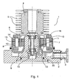
- the vacuum pump according to the invention comprises a body 1, made of metal, of which the drawing shows base 2 where an outlet port 3 and seats for other pump components are formed. Said components will not be described in detail since they are prior art.
- the vacuum pump further has a rotor 4 with rotor discs 5, intended to cooperate with stator rings integral with the pump body to form a plurality of pumping stages.
- the stator rings and the external part of body 1 with which they are integral are not shown in the drawing, since they are not affected by the present invention.
- Rotor 4 is preferably made of a lightweight metal, e.g. an aluminium alloy.
- Rotor discs 5 may be planar discs or discs with inclined and closely hollow spaced vanes, as usual in such pumps.
- Rotor 4 has, on its side directed towards base 2 of pump body 1, a bell-shaped axial cavity 6, at the centre of which rotating shaft 7 supporting rotor 4 is located. Said cavity 6 is defined within a cup-shaped portion 14 of rotor 4, which portion acts as the rotor of the motor, generally shown at 8, driving pump 1. Shaft 7 is located in a seat formed inside a hollow cylindrical portion 9 of base 2, extending upwards from base 2 towards rotor 4, and is supported by rotating support members, such as rolling bearings 10.
- motor 8 is a cup-type motor, comprising an internal stator 11 and an external stator 12 separated by a hollow space 13 where portion 14 of rotor 4 is received.
- pump rotor 4 and rotor portion 14 acting as the rotor of motor 8 could be two separate members fastened to each other in any suitable manner.
- motor rotor 14 is preferably made of a lightweight non-magnetic material, e.g. an aluminium alloy, like vacuum pump rotor 4.
- Stators 11, 12 of motor 8 are mounted in a housing 15, and one of them is equipped with windings 16 for supplying stators 11, 12 with power.
- windings 16 are provided on external stator 12. In the alternative, they may be provided on internal stator 11.
- the rotor rings are provided only in the upper rotor portion, outside motor 8.
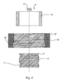
- FIG. 2 the drawing shows, from top to down: rotor 14 of pump motor 8, in cross-sectional view; external stator 12 of motor 8, also in cross-sectional view; and the external surface of internal stator 11 of motor 8.
- the external surface of stator 11 and the internal surface of stator 12 have each a set of substantially helical grooves 17 and 18, respectively, for gas pumping. It is to be appreciated that the winding direction of said helical grooves 17, 18 depends on the rotation direction of the motor rotor, indicated by arrow F1 in Fig. 2.
- a single Holweck pumping stage defined by the internal or the external motor stator, might be provided. Still depending on the performance desired, one or more additional cascaded pumping stages might be provided.
- grooves 17 and 18 might be alternatively formed on the external and/or internal surface of rotor 14.
- grooves 17, 18 might be formed according to different variant embodiments, for instance according to a variable pitch helix, with non-rectangular (e.g. trapezoidal) groove section, with variable groove size, etc.
- motor stators 11, 12 are formed by a plurality of superimposed rings. That structure allows forming very easily grooves 17 and/or 18 when motor 8 comprises the Holweck pumping stage(s).
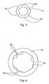
- each ring 11' of stator 11 and/or each ring 12' of stator 12 can have a plurality of notches 21 and 22, respectively, on its internal and external surface, respectively.
- said rings 11', 12' could be obtained by pressing. During assembling, successive rings are superimposed and stacked with an angular offset, so that the respective notches give rise to said helical grooves 17, 18.
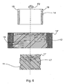
- FIGs. 5 and 6 a second embodiment of the invention is shown.
- a plurality of through holes 19 are formed in rotor 14, above internal and external stators 11, 12, said holes putting the hollow space between external stator 12 and rotor 14 in communication with the hollow space between rotor 14 and internal stator 11. In that way, part of the gas will be pumped so as to flow downwards in the hollow space between external stator 12 and rotor 14, and the remaining part will be pumped so as to flow downwards in the hollow space between rotor 14 and internal stator 11.
- Fig. 6 shows motor 8, constructed so as to form a pair of Holweck pumping stages in parallel.
- the external surface of stator 11 and the internal surface of stator 12 i.e., the surfaces facing rotor 14
- the winding direction of said helical grooves 17' and 18' depends on the rotation direction of the motor rotor, indicated by arrow F2 in Fig. 6.
Landscapes
- Engineering & Computer Science (AREA)
- Mechanical Engineering (AREA)
- General Engineering & Computer Science (AREA)
- Power Engineering (AREA)
- Non-Positive Displacement Air Blowers (AREA)
- Connection Of Motors, Electrical Generators, Mechanical Devices, And The Like (AREA)
Applications Claiming Priority (2)
| Application Number | Priority Date | Filing Date | Title |
|---|---|---|---|
| ITTO20030421 | 2003-06-05 | ||
| IT000421A ITTO20030421A1 (it) | 2003-06-05 | 2003-06-05 | Pompa da vuoto compatta |
Publications (3)
| Publication Number | Publication Date |
|---|---|
| EP1484508A2 EP1484508A2 (en) | 2004-12-08 |
| EP1484508A3 EP1484508A3 (en) | 2006-01-04 |
| EP1484508B1 true EP1484508B1 (en) | 2008-01-30 |
Family
ID=33156376
Family Applications (1)
| Application Number | Title | Priority Date | Filing Date |
|---|---|---|---|
| EP04009519A Expired - Lifetime EP1484508B1 (en) | 2003-06-05 | 2004-04-22 | Compact vacuum pump |
Country Status (5)
| Country | Link |
|---|---|
| US (1) | US7354254B2 (it) |
| EP (1) | EP1484508B1 (it) |
| JP (1) | JP2004360698A (it) |
| DE (1) | DE602004011583T2 (it) |
| IT (1) | ITTO20030421A1 (it) |
Families Citing this family (12)
| Publication number | Priority date | Publication date | Assignee | Title |
|---|---|---|---|---|
| GB0409139D0 (en) * | 2003-09-30 | 2004-05-26 | Boc Group Plc | Vacuum pump |
| US20080129135A1 (en) * | 2006-11-07 | 2008-06-05 | Inventec Corporation | Motor structure |
| EP2096317B1 (en) | 2008-02-27 | 2012-08-15 | Agilent Technologies, Inc. | Method for manufacturing the rotor assembly of a rotating vacuum pump |
| DE102009035332A1 (de) * | 2009-07-30 | 2011-02-03 | Pfeiffer Vacuum Gmbh | Vakuumpumpe |
| DE202009013629U1 (de) * | 2009-10-09 | 2011-02-24 | Oerlikon Leybold Vacuum Gmbh | Vakuum-Wälzlageranordnung sowie Vakuumpumpe |
| JP5763660B2 (ja) * | 2010-09-28 | 2015-08-12 | エドワーズ株式会社 | 排気ポンプ |
| JP5919745B2 (ja) * | 2011-11-15 | 2016-05-18 | 株式会社島津製作所 | 真空ポンプ |
| DE102012005931B4 (de) * | 2012-03-26 | 2014-08-21 | Thyssenkrupp Presta Aktiengesellschaft | Grundlast für eine KGT-Anordnung |
| DE102013214662A1 (de) | 2013-07-26 | 2015-01-29 | Pfeiffer Vacuum Gmbh | Vakuumpumpe |
| JP2018035684A (ja) | 2016-08-29 | 2018-03-08 | 株式会社島津製作所 | 真空ポンプ |
| GB2579028A (en) * | 2018-11-14 | 2020-06-10 | Edwards Ltd | Molecular drag stage |
| GB2607339A (en) * | 2021-06-04 | 2022-12-07 | Edwards Ltd | Holweck drag pump |
Family Cites Families (23)
| Publication number | Priority date | Publication date | Assignee | Title |
|---|---|---|---|---|
| US1810083A (en) * | 1927-11-30 | 1931-06-16 | Norinder Ernst Harald | High vacuum molecular pump |
| US2313682A (en) * | 1940-11-05 | 1943-03-09 | Bendix Aviat Corp | Compass system |
| US2653257A (en) * | 1952-03-22 | 1953-09-22 | Singer Mfg Co | Low inertia type drag cup motor |
| DE2433770C2 (de) * | 1974-07-13 | 1982-09-02 | Interelectric AG, 6072 Sachseln | Verfahren zum Herstellen eines Stators für eine elektrische Maschine |
| US4140441A (en) * | 1977-04-11 | 1979-02-20 | Patterson Williams G | Turbomolecular pump lubrication system |
| US4491753A (en) * | 1981-03-19 | 1985-01-01 | Mitsubishi Denki Kabushiki Kaisha | Low inertial variable speed induction motor |
| DE3526948A1 (de) * | 1984-07-28 | 1986-01-30 | Papst-Motoren GmbH & Co KG, 7742 St Georgen | Gehaeuseglocke fuer einen elektrokleinmotor |
| JPS6365883A (ja) * | 1986-09-05 | 1988-03-24 | 三菱電機株式会社 | ゴルフのパタ−練習装置 |
| US4854034A (en) * | 1988-05-27 | 1989-08-08 | General Electric Company | Method for producing a stack of laminations with skewed conductor slots |
| JPH0786550B2 (ja) * | 1988-06-13 | 1995-09-20 | 三菱原子燃料株式会社 | 下部ノズルの取付装置 |
| JPH03237296A (ja) * | 1990-02-09 | 1991-10-23 | Shimadzu Corp | ターボ分子ポンプ |
| JPH03237297A (ja) * | 1990-02-09 | 1991-10-23 | Shimadzu Corp | ターボ分子ポンプ |
| JP3102488B2 (ja) * | 1990-04-25 | 2000-10-23 | 株式会社日立製作所 | 液晶表示装置の駆動方法 |
| JPH07264810A (ja) * | 1994-03-17 | 1995-10-13 | Okuma Mach Works Ltd | 液冷モータ |
| FR2723767B1 (fr) * | 1994-08-19 | 1997-01-03 | Cit Alcatel | Pompe a vide turbomoleculaire |
| ITPN960017A1 (it) * | 1996-03-12 | 1997-09-12 | Sole Spa | Macchina elettrica, in particolare motore elettrico |
| JPH09303288A (ja) * | 1996-05-16 | 1997-11-25 | Daikin Ind Ltd | ターボ分子ポンプの翼 |
| US5965274A (en) * | 1997-11-13 | 1999-10-12 | Lockheed Martin Energy Research Corporation | Electronic circuits having NiAl and Ni3 Al substrates |
| JP4520636B2 (ja) * | 1998-05-26 | 2010-08-11 | ライボルト ヴァークウム ゲゼルシャフト ミット ベシュレンクテル ハフツング | シャシ、ロータ及びケーシングを有する摩擦真空ポンプ並びにこの形式の摩擦真空ポンプを備えた装置 |
| ITTO980453A1 (it) * | 1998-05-27 | 1999-11-29 | Varian Spa | Pompa da vuoto compatta |
| JP2000110758A (ja) * | 1998-10-06 | 2000-04-18 | Aiteku Kk | 空気機械及びこれに用いるエレメント |
| US6179573B1 (en) * | 1999-03-24 | 2001-01-30 | Varian, Inc. | Vacuum pump with inverted motor |
| JP4657463B2 (ja) * | 2001-02-01 | 2011-03-23 | エドワーズ株式会社 | 真空ポンプ |
-
2003
- 2003-06-05 IT IT000421A patent/ITTO20030421A1/it unknown
-
2004
- 2004-04-22 DE DE602004011583T patent/DE602004011583T2/de not_active Expired - Lifetime
- 2004-04-22 EP EP04009519A patent/EP1484508B1/en not_active Expired - Lifetime
- 2004-05-28 US US10/857,192 patent/US7354254B2/en not_active Expired - Fee Related
- 2004-06-03 JP JP2004166376A patent/JP2004360698A/ja not_active Ceased
Also Published As
| Publication number | Publication date |
|---|---|
| JP2004360698A (ja) | 2004-12-24 |
| EP1484508A3 (en) | 2006-01-04 |
| DE602004011583T2 (de) | 2009-01-29 |
| ITTO20030421A1 (it) | 2004-12-06 |
| US7354254B2 (en) | 2008-04-08 |
| US20040265152A1 (en) | 2004-12-30 |
| EP1484508A2 (en) | 2004-12-08 |
| DE602004011583D1 (de) | 2008-03-20 |
Similar Documents
| Publication | Publication Date | Title |
|---|---|---|
| EP1484508B1 (en) | Compact vacuum pump | |
| US9729037B2 (en) | Brushless motor | |
| EP1124302A3 (en) | Divisible lamination brushless pump-motor having fluid cooling system | |
| EP1234115B1 (en) | Radial flow turbomolecular vacuum pump | |
| EP0433212B1 (en) | Slotted rotor lubrication system | |
| JP2006230087A (ja) | 電動機,圧縮機及び空気調和機 | |
| US6215212B1 (en) | Shaftless rotor construction | |
| US6744163B2 (en) | Vibration type brushless motor | |
| US20080170935A1 (en) | Axial-flow fan | |
| US5542825A (en) | Turbomolecular vacuum pump | |
| EP2039940A2 (en) | Radially staged microscale turbomolecular pump | |
| CA2454877C (en) | External rotor motor | |
| US10250090B2 (en) | Rotor, motor, pump and cleaning apparatus | |
| US6158986A (en) | Compact vacuum pump | |
| US5796204A (en) | Brushless motor with a stator core integral with a holder | |
| US5927940A (en) | Double-flow gas friction pump | |
| US4732530A (en) | Turbomolecular pump | |
| US20070014677A1 (en) | Pump | |
| US6509663B2 (en) | Stepping motor | |
| US20110193445A1 (en) | Inner-Roter-Type Motor and Claw-Pole Member Thereof | |
| JPS6365832B2 (it) | ||
| US20040228721A1 (en) | Fuel pump | |
| KR20010022360A (ko) | 연료 공급 장치 | |
| US4593216A (en) | Rotary stepping motor having improved construction | |
| KR102896621B1 (ko) | 로터리 공기 압축기 |
Legal Events
| Date | Code | Title | Description |
|---|---|---|---|
| PUAI | Public reference made under article 153(3) epc to a published international application that has entered the european phase |
Free format text: ORIGINAL CODE: 0009012 |
|
| AK | Designated contracting states |
Kind code of ref document: A2 Designated state(s): AT BE BG CH CY CZ DE DK EE ES FI FR GB GR HU IE IT LI LU MC NL PL PT RO SE SI SK TR |
|
| AX | Request for extension of the european patent |
Extension state: AL HR LT LV MK |
|
| PUAL | Search report despatched |
Free format text: ORIGINAL CODE: 0009013 |
|
| AK | Designated contracting states |
Kind code of ref document: A3 Designated state(s): AT BE BG CH CY CZ DE DK EE ES FI FR GB GR HU IE IT LI LU MC NL PL PT RO SE SI SK TR |
|
| AX | Request for extension of the european patent |
Extension state: AL HR LT LV MK |
|
| RIC1 | Information provided on ipc code assigned before grant |
Ipc: H02K 7/14 20060101ALI20051112BHEP Ipc: F04D 19/04 20060101AFI20040830BHEP |
|
| 17P | Request for examination filed |
Effective date: 20060330 |
|
| AKX | Designation fees paid |
Designated state(s): DE FR GB IT |
|
| 17Q | First examination report despatched |
Effective date: 20060811 |
|
| GRAP | Despatch of communication of intention to grant a patent |
Free format text: ORIGINAL CODE: EPIDOSNIGR1 |
|
| GRAS | Grant fee paid |
Free format text: ORIGINAL CODE: EPIDOSNIGR3 |
|
| GRAA | (expected) grant |
Free format text: ORIGINAL CODE: 0009210 |
|
| AK | Designated contracting states |
Kind code of ref document: B1 Designated state(s): DE FR GB IT |
|
| REG | Reference to a national code |
Ref country code: GB Ref legal event code: FG4D |
|
| REF | Corresponds to: |
Ref document number: 602004011583 Country of ref document: DE Date of ref document: 20080320 Kind code of ref document: P |
|
| ET | Fr: translation filed | ||
| PLBE | No opposition filed within time limit |
Free format text: ORIGINAL CODE: 0009261 |
|
| STAA | Information on the status of an ep patent application or granted ep patent |
Free format text: STATUS: NO OPPOSITION FILED WITHIN TIME LIMIT |
|
| 26N | No opposition filed |
Effective date: 20081031 |
|
| REG | Reference to a national code |
Ref country code: GB Ref legal event code: 732E Free format text: REGISTERED BETWEEN 20110505 AND 20110511 |
|
| PGFP | Annual fee paid to national office [announced via postgrant information from national office to epo] |
Ref country code: FR Payment date: 20110426 Year of fee payment: 8 |
|
| PGFP | Annual fee paid to national office [announced via postgrant information from national office to epo] |
Ref country code: GB Payment date: 20110420 Year of fee payment: 8 |
|
| REG | Reference to a national code |
Ref country code: DE Ref legal event code: R081 Ref document number: 602004011583 Country of ref document: DE Owner name: AGILENT TECHNOLOGIES, INC., US Free format text: FORMER OWNER: VARIAN S.P.A., LEINI, IT Effective date: 20110809 Ref country code: DE Ref legal event code: R082 Ref document number: 602004011583 Country of ref document: DE Representative=s name: DILG HAEUSLER SCHINDELMANN PATENTANWALTSGESELL, DE Effective date: 20110809 Ref country code: DE Ref legal event code: R081 Ref document number: 602004011583 Country of ref document: DE Owner name: AGILENT TECHNOLOGIES ITALIA S.P.A., IT Free format text: FORMER OWNER: VARIAN S.P.A., LEINI, IT Effective date: 20110809 |
|
| PGFP | Annual fee paid to national office [announced via postgrant information from national office to epo] |
Ref country code: IT Payment date: 20110421 Year of fee payment: 8 |
|
| REG | Reference to a national code |
Ref country code: FR Ref legal event code: TP Owner name: AGILENT TECHNOLOGIES ITALIA, S.P.A., IT Effective date: 20110922 |
|
| PGFP | Annual fee paid to national office [announced via postgrant information from national office to epo] |
Ref country code: DE Payment date: 20120425 Year of fee payment: 9 |
|
| GBPC | Gb: european patent ceased through non-payment of renewal fee |
Effective date: 20120422 |
|
| REG | Reference to a national code |
Ref country code: FR Ref legal event code: ST Effective date: 20121228 |
|
| PG25 | Lapsed in a contracting state [announced via postgrant information from national office to epo] |
Ref country code: GB Free format text: LAPSE BECAUSE OF NON-PAYMENT OF DUE FEES Effective date: 20120422 |
|
| REG | Reference to a national code |
Ref country code: DE Ref legal event code: R082 Ref document number: 602004011583 Country of ref document: DE Representative=s name: DILG HAEUSLER SCHINDELMANN PATENTANWALTSGESELL, DE |
|
| PG25 | Lapsed in a contracting state [announced via postgrant information from national office to epo] |
Ref country code: FR Free format text: LAPSE BECAUSE OF NON-PAYMENT OF DUE FEES Effective date: 20120430 Ref country code: IT Free format text: LAPSE BECAUSE OF NON-PAYMENT OF DUE FEES Effective date: 20120422 |
|
| REG | Reference to a national code |
Ref country code: DE Ref legal event code: R082 Ref document number: 602004011583 Country of ref document: DE Representative=s name: DILG HAEUSLER SCHINDELMANN PATENTANWALTSGESELL, DE |
|
| REG | Reference to a national code |
Ref country code: DE Ref legal event code: R082 Ref document number: 602004011583 Country of ref document: DE Representative=s name: DILG HAEUSLER SCHINDELMANN PATENTANWALTSGESELL, DE Effective date: 20130521 Ref country code: DE Ref legal event code: R082 Ref document number: 602004011583 Country of ref document: DE Representative=s name: DILG HAEUSLER SCHINDELMANN PATENTANWALTSGESELL, DE Effective date: 20130204 Ref country code: DE Ref legal event code: R081 Ref document number: 602004011583 Country of ref document: DE Owner name: AGILENT TECHNOLOGIES, INC., US Free format text: FORMER OWNER: AGILENT TECHNOLOGIES ITALIA S.P.A., CERNUSCO SUL NAVIGLIO, IT Effective date: 20130521 |
|
| PG25 | Lapsed in a contracting state [announced via postgrant information from national office to epo] |
Ref country code: DE Free format text: LAPSE BECAUSE OF NON-PAYMENT OF DUE FEES Effective date: 20131101 |
|
| REG | Reference to a national code |
Ref country code: DE Ref legal event code: R119 Ref document number: 602004011583 Country of ref document: DE Effective date: 20131101 |