EP1234115B1 - Radial flow turbomolecular vacuum pump - Google Patents
Radial flow turbomolecular vacuum pump Download PDFInfo
- Publication number
- EP1234115B1 EP1234115B1 EP00978637A EP00978637A EP1234115B1 EP 1234115 B1 EP1234115 B1 EP 1234115B1 EP 00978637 A EP00978637 A EP 00978637A EP 00978637 A EP00978637 A EP 00978637A EP 1234115 B1 EP1234115 B1 EP 1234115B1
- Authority
- EP
- European Patent Office
- Prior art keywords
- blades
- pump
- radial
- gas
- turbomolecular
- Prior art date
- Legal status (The legal status is an assumption and is not a legal conclusion. Google has not performed a legal analysis and makes no representation as to the accuracy of the status listed.)
- Revoked
Links
Images


Classifications
-
- F—MECHANICAL ENGINEERING; LIGHTING; HEATING; WEAPONS; BLASTING
- F04—POSITIVE - DISPLACEMENT MACHINES FOR LIQUIDS; PUMPS FOR LIQUIDS OR ELASTIC FLUIDS
- F04D—NON-POSITIVE-DISPLACEMENT PUMPS
- F04D17/00—Radial-flow pumps, e.g. centrifugal pumps; Helico-centrifugal pumps
- F04D17/08—Centrifugal pumps
- F04D17/10—Centrifugal pumps for compressing or evacuating
- F04D17/12—Multi-stage pumps
- F04D17/127—Multi-stage pumps with radially spaced stages, e.g. for contrarotating type
-
- F—MECHANICAL ENGINEERING; LIGHTING; HEATING; WEAPONS; BLASTING
- F04—POSITIVE - DISPLACEMENT MACHINES FOR LIQUIDS; PUMPS FOR LIQUIDS OR ELASTIC FLUIDS
- F04D—NON-POSITIVE-DISPLACEMENT PUMPS
- F04D17/00—Radial-flow pumps, e.g. centrifugal pumps; Helico-centrifugal pumps
- F04D17/08—Centrifugal pumps
- F04D17/16—Centrifugal pumps for displacing without appreciable compression
- F04D17/168—Pumps specially adapted to produce a vacuum
-
- F—MECHANICAL ENGINEERING; LIGHTING; HEATING; WEAPONS; BLASTING
- F04—POSITIVE - DISPLACEMENT MACHINES FOR LIQUIDS; PUMPS FOR LIQUIDS OR ELASTIC FLUIDS
- F04D—NON-POSITIVE-DISPLACEMENT PUMPS
- F04D19/00—Axial-flow pumps
- F04D19/02—Multi-stage pumps
- F04D19/04—Multi-stage pumps specially adapted to the production of a high vacuum, e.g. molecular pumps
- F04D19/042—Turbomolecular vacuum pumps
Definitions
- the invention relates generally to the field of vacuum pumps and compressors.
- the present invention relates to radial flow turbomolecular vacuum pumps and methods for operating radial flow pumps.
- Prior art vacuum pumping systems are typically continuous flow compression systems that evacuate gas from a vacuum chamber at low pressure, for example 1.33 x 10 -4 Pa (10 -6 torr), and then compress the gas to atmospheric pressure so that the gas may be discharged to the atmosphere.
- Such prior art pumping systems would typically include a high vacuum pump, such as a turbomolecular pump or a diffusion pump, capable of evacuating to high vacuum. This pump would be followed by a fore pump such as an oil sealed rotary pump or a diaphragm pump, which would further compress the gas and exhaust the gas to the atmosphere.
- Vacuum pumps are used for numerous applications including vacuum based instrumentation, such as mass spectrometers, electron microscopes, and various surface analysis tools that use ion or electron beams.
- vacuum based instruments are typically designed for use in dedicated laboratories because of the size, weight, and service requirements of the vacuum pump and other hardware. Consequently, analysis is typically performed by trausporting the material to be analyzed to a dedicated laboratory facility. Unfortunately, not all materials that require analysis can be conveniently transported. There is a significant need for portable vacuum based analysis equipment that can be transported to the location of the analysis.
- Storage vacuum pumps include ion pumps, getter pumps and sorption pumps. These pumps operate by capturing gas molecules within the pump and storing them. The molecules are stored up to some capacity limit of the pump and then the pump must be discarded or reprocessed, which is both inconvenient and expensive.
- Storage-type vacuum pumps have numerous disadvantages. Storage-type vacuum pumps have poor pumping speed for certain gases. They are also difficult to restart after a shutdown. In addition, if the pumps store toxic gases, there is a danger of poisoning the user if the pump malfunctions. Notwithstanding the disadvantages of storage type vacuum pumps, these pumps are only slightly smaller than the compression type pumps.
- the present invention relates to compact vacuum pumps that can be used in instrunentation where the application may be portable, hand held or space limited.
- a principal discovery of the present invention is that an efficient compact turbomolecular vacuum pump can be constructed having a radial flow design where the dimension of the gas flow path in the radial direction is greater than the dimension of the gas flow path in the axial direction.
- the present invention provides a radial turbomolecular vacuum pump comprising: a gas inlet; a rotor comprising: a first rotor surface that is positioned in a substantially radial direction, and a plurality of blades being in fluid communication with the gas inlet and extending from the first rotor surface in a substantially axial direction, the plurality of blades being arranged in concentric rings of blades and being tilted towards the radial direction; a stator comprising: a first stator surface that is positioned proximate to the first rotor surface in the substantially radial direction; and a first and second plurality of vanes extending from the first stator surface, the first and second plurality of vanes being arranged in concentric stator rings and being disposed between the concentric rings of the plurality of blades; and a gas outlet that is in fluid communication with the plurality of blades and the first and the second plurality of vanes, wherein rotation of the rotor relative to the stator causes gas to be mole
- the present invention provides a radial turbomolecular vaccum pump comprising: a gas inlet; a rotor comprising: a rotor surface that is positioned in a substantially radial direction; and a plurality of blades being in fluid communication with the gas inlet and extending from the rotor surface in a substantially axial direction, the plurality of blades tilted towards the radial direction; a casing comprising: a first stator surface that is positioned proximate to the first rotor surface in the substantially radial direction; and a first and second plurality of vanes extending from the first stator surface, the first and second plurality of vanes being arranged in concentric stator rings ; a gas outlet that is in fluid communication with the plurality of blades and the first and second plurality of vanes, wherein rotation of the rotor relative to the casing causes gas to be molecularly pumped from the gas inlet to the gas outlet; and a fore pump coupled to the gas outlet
- the present invention features a radial turbomolecular vacuum pump that includes a gas inlet, a gas outlet, a rotor, and a casing.
- the rotor includes a first rotor surface that is positioned in a substantially radial direction.
- a first plurality of blades extends from the first rotor surface in a substantially axial direction.
- at least one blade of the first plurality of blades is shaped to increase pumping efficiency.
- a support ring that reduces reflection due to centrifugal force may be positioned around at least one blade of the plurality of blades.
- the rotor and at least one blade of the first plurality of blades may be integrally formed from one piece of material.
- the first rotor surface may include at least one cavity that is dimensioned to receive and to retain at least one blade of the first plurality of blades.
- the at least one blade of the first plurality of blades may include a dovetail and the at least one cavity may be adapted to receive the dovetail.
- the dovetail may be oriented in a substantially radial direction or in a substantially circumferentially direction.
- the casing includes a first stator surface that is positioned proximate to the first rotor surface in the substantially radial direction.
- the stator is separate from the casing.
- a first and second plurality of vanes extend from the first stator surface and generally forms an annulus therebetween for receiving the first plurality of blades.
- the annulus may be a groove.
- At least one vane of the first and second plurality of vanes and the first stator surface may be integrally formed from one piece of material.
- the stator may include at least one cavity that is dimensioned to receive and retain at least one of the vanes of the first and second plurality of vanes.
- a drive shaft is coupled to the rotor and is positioned in the substantially axial direction.
- a motor is coupled to the drive shaft and rotates the rotor relative to the stator.
- the rotor is directly coupled to the motor without the use of a drive shaft.
- the rotation of the rotor relative to the casing causes gas to be pumped from the gas inlet to the gas outlet.
- a fore pump such as a mechanical pump is typically coupled to the gas outlet.
- a processor is electrically coupled to the motor and to a pressure sensor that is positioned in fluid communication with the pump. The pressure sensor generates a signal that is proportional to a pressure achieved by the pump and the processor generates a signal that controls a speed of the motor in response to the pressure.
- the vacuum pump further includes a second rotor surface that is positioned in a substantially radial direction.
- a second plurality of blades extends from the second rotor surface in a substantially axial direction opposite that of the first plurality of blades.
- a second stator surface is positioned proximate to the second rotor surface in the substantially radial direction.
- a third and fourth plurality of vanes extend from the second stator surface and generally forming an annulus therebetween for receiving the second plurality of blades.
- the rotor and stator further comprise a second stage.
- the second stage includes a rotor surface that is positioned in a substantially radial direction.
- a plurality of blades extends from the rotor surface in a substantially axial direction.
- the second stage includes a stator surface that is positioned proximate to the second stage rotor surface in the substantially radial direction.
- a first and second plurality of vanes extend from the stator surface of the second stator and generally form an annulus therebetween for receiving the plurality of blades.
- the present invention also features a method of pumping gas with a radial turbomolecular vacuum pump, the method comprising receiving a gas through a gas inlet; rotating a plurality of blades that are tilted towards the radial direction, and are substantially axially disposed and arranged in concentric rings relative to a first and second plurality of vanes arranged in concentric stator rings that are disposed between the concentric rings of the plurality of blades, wherein the relative motion of the plurality of blades and the first and second plurality of vanes causes gas to be molecularly pumped in a substantially radial direction from the concentric rings of blades through the concentric stator rings; and exhausting the gas through a gas outlet.
- the present invention also features a method for pumping a gas that includes the step of rotating a plurality of substantially axially disposed blades relative to a first and second plurality of vanes that generally form an annulus therebetween for receiving the first plurality of blades.
- the relative motion of the plurality of blades and the first and second plurality of vanes causes gas to be pumped in a substantially radial direction from a gas inlet to a gas outlet.
- the gas may be pumped outwardly or inwardly in a substantially radial direction.
- method for pumping a gas further includes rotating a second plurality of substantially axially disposed blades relative to a third and fourth plurality of vanes that generally form an annulus therebetween for receiving the second plurality of blades.
- the relative motion of the second plurality of blades and the third and fourth plurality of vanes causes gas to be pumped in a substantially radial direction from a gas inlet to a gas outlet.
- the gas may be pumped outwardly or inwardly in a substantially radial direction.
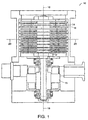
- Fig. 1 illustrates a prior art axial flow turbomolecular pump 10.
- the pump 10 includes a rotor 12 having a plurality of axial blades 14.
- a plurality of stator vanes 16 is positioned to receive the plurality of axial blades 14.
- a motor 15 drives the rotor 12 so that each of the plurality of blades 14 passes though a respective one of the plurality of stator vanes 16. Compression is achieved in a direction that is substantially parallel to an axial centerline 18. That is, the dimension of the gas flow path parallel the axial centerline 18 is much greater than the dimension of the gas flow path parallel to a radial centerline 20.
- Many stages of rotor blades and stator vanes are required to achieve the necessary compression and pumping speed. Typically prior art pumping speeds in liters/sec are approximately 50 to 10001/sec.
- Typical prior art axial flow turbomolecular pumps are designed to rotate the rotor 12 so that a blade tip speed is approximately 400 m/sec.
- the rotor diameter is sized to greater than approximately 75mm. The dimension of the rotor diameter typically sets the minimum diameter for the pump assembly.
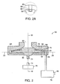
- Fig. 2 illustrates one embodiment of a radial flow turbomolecular vacuum pump 50 of the present invention.
- radial flow we mean that the dimension of the gas flow path parallel to the radial centerline 20 is greater than the dimension of the gas flow path parallel to the axial centerline 18.
- the pump 50 includes a gas inlet 52, a gas outlet 54, a rotor 56, and a casing 58.
- a sensor may be in fluidic communication with the gas inlet 52 or the gas outlet 54.
- the rotor 56 includes a first rotor surface 62 that is positioned in a substantially parallel direction to the radial centerline 20.
- the rotor 56 may be formed from a high strength aluminum alloy.
- a first plurality of blades 64 extends from the first rotor surface 62 in a substantially parallel direction to the axial centerline 18. In one embodiment, at least one blade of the first plurality of blades 64 is shaped to increase pumping efficiency.
- a support ring 63 that reduces deflection due to centrifugal force may be positioned around at least one blade of the plurality of blades.
- one side of the rotor comprises a molecular drag pump.
- the first plurality of blades 64 can be attached to the rotor 56 by numerous means known in the art.
- the rotor 56 and at least one blade of the first plurality of blades 64 is integrally formed from one piece of material.
- the blades are mounted onto the rotor.
- the first rotor surface 62 includes at least one cavity 66 that is dimensioned to receive and to retain at least one blade of the first plurality of blades 64.
- the at least one blade of the first plurality of blades 64 may include a dovetail 68 and the at least one cavity 66 may be adapted to receive the dovetail 68.
- the dovetail 68 may be oriented in the radial direction or in the circumferential direction.
- a stator 59 includes a first stator surface 70 that is positioned proximate to the first rotor surface 62 parallel to the radial centerline 20.
- the stator 59 is formed in the casing 58.
- a first and second plurality of vanes 72 extend from the first stator surface 70 and generally form an annulus therebetween for receiving the first plurality of blades 64.
- the annulus may be a groove.
- a space between at least one blade of the first plurality of blades 64 and the first and second plurality of vanes 72 is approximately 0.2mm.
- At least one vane of the first and second plurality of vanes 72 and the first stator surface 70 may be integrally formed from one piece of material.
- the stator may include at least one cavity that is dimensioned to receive and retain at least one of the vanes.
- a drive shaft 74 is coupled to the rotor 56 and is positioned in the axial direction 18.
- a motor 76 is coupled to the drive shaft 74 and rotates the rotor 56 relative to the casing 58.
- the rotor 56 is directly coupled to the motor 76 without the use of a drive shaft.
- permanent magnets (not shown) can be embedded in the rotor 56 and driven by stator coils (not shown) positioned in the facing surface.
- magnetic bearings can be used to levitate the rotor 56.
- the motor is a brushless DC motor and the speed of the motor 76 is approximately 50,000 to 150,000 RPM.
- the rotation of the rotor 56 relative to the casing 58 causes gas to be pumped radially outward away from the axial centerline 18 or radially inward toward the axial centerline 18, depending on the sense of rotation, from the gas inlet 52 to the gas outlet 54.
- a fore pump 78 such as a scroll pump, is typically coupled in series with the gas outlet 54.
- a molecular drag pump can also be used.
- One advantage of the radial flow turbomolecular vacuum pump 50 of the present invention is that the axial dimension of the pump is much less than the axial dimension of prior art axial flow turbomolecular vacuum pumps because the compression is achieved radially.
- the radial flow turbomolecular vacuum pump 50 of the present invention is particularly efficient for low pumping speeds, less than 50 liters/sec.
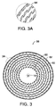
- Fig. 3 illustrates an axial view of the rotor 56 used in the radial flow turbomolecular vacuum pump 50 of the present invention.
- the rotor 56 comprises the first rotor surface 62 and the first plurality of blades 64 that extends from the first rotor surface in the axial direction 18.
- the first plurality of blades 64 are arranged in corresponding concentric rings 82.
- the first and second plurality of vanes (not shown) are arranged in concentric stator rings between the concentric rings 82 of first plurality of blades 64.
- the gas flow moves radially from one concentric ring of blades, through a corresponding concentric stator ring and then to the next concentric ring of rotor blades and stator blades.
- One advantage of the rotor 56 of the present invention is that the rotor 56 can be machined from one side in one machining operation, which reduces the manufacturing cost of the pump 50.
- the first plurality of blades 64 are shaped and positioned to achieve a certain pumping speed, compression, and efficiency.
- the pitch of each blade of the first plurality of blades 64 generally determines the pumping speed and compression. For example, tilting the blades towards the radial direction 20, will generally result in a higher pumping speed. Tilting the blades towards the circumferential direction, will result in higher compression, which generally results in lower pumping speed.
- the inner blades (blades closest to the axial centerline 18) are gradually tilted towards the radial direction for high pumping speed and the outer blades (blades farthest from the axial centerline 18) are gradually tilted towards the circumferential direction for higher compression.
- the gas is compressed, there is more pumping in the blades furthest from the axial centerline 18, therefore achieving higher compression.
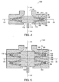
- Fig. 4 illustrates a radial flow turbomolecular vacuum pump 100 according to the present invention having rotor blades extending from two surfaces.
- the pump 100 is similar to the turbomolecular vacuum pump 50 of Fig. 2.
- the pump 100 further includes a second rotor surface 102 that is positioned in the radial direction 20.
- a second plurality of blades 104 extends from the second rotor surface 102 in the axial direction 18 opposite that of a first plurality of blades 64.
- a second stator surface 108 is positioned proximate to the second rotor surface 102 in the radial direction 20.
- a third and fourth plurality of vanes 110 extend from the second stator surface 108 and generally form an annulus therebetween for receiving the second plurality of blades 104.
- the rotation of a rotor 112 relative to a casing 114 causes gas to be pumped radially outward away from the axial centerline 18 or radially toward the axial centerline 18, depending on the sense of rotation, from a gas inlet 116 to the gas outlet 118.
- the first 70 and the second stator surface 108 pump in parallel to achieve a higher pump speed. That is, the gas is pumped radially outward or radially inward on both the first 62 and the second rotor surface 102.
- the first 70 and the second stator surface 108 pump in series to achieve increased compression. That is, the gas is pumped radially outward on one of the first 64 and second rotor surface 102 and radially inward on the other of the first 64 and second rotor surface 102.
- Fig. 5 illustrates an embodiment of a radial flow turbomolecular vacuum pump 150 according to the present invention having a first 152 and a second stage 154.
- the pump 150 is similar to the turbomolecular vacuum pump 50 of Fig. 4, but includes a first 156 and a second rotor 158, each having a first 62 and a second rotor surface 102.
- a first 64 and second plurality of blades 104 extends from the first rotor 156 in the axial direction 18.
- a first 64 and second plurality of blades 104 extend from the second rotor 158 in the axial direction 18.
- a first 70 and a second stator surface 108 is positioned proximate to the first 64 and the second rotor surface 102, respectively, in the radial direction 20.
- a first and second plurality of vanes 72 extend from the first stator surface 70 and generally form an annulus therebetween for receiving the first plurality of blades 64.
- a third and fourth plurality of vanes 110 extend from the second stator surface 108 and generally form an annulus therebetween for receiving the second plurality of blades 104.
- the first 152 and the second stages 154 are configured to pump in series to achieve increased compression. That is, the gas is pumped radially outward or radially inward, depending on the sense of the rotation, in both the first 152 and second stage 154.
- the first 152 and the second stage 154 are configured to pump in parallel to achieve a higher pumping speed. That is, the gas is pumped radially outward in one stage and radially inward in the other stage.
- Other embodiments of the turbomolecular vacuum pump the present invention includes more than two stages to achieve additional compression or additional pumping speed.
- Fig. 6 illustrates a sectional view of an embodiment of a radial flow turbomolecular vacuum pump 200 according to the present invention.
- the turbomolecular vacuum pump 200 includes a rotor 202 having a first rotor surface 204 that is positioned in the substantially radial direction 20.
- a first plurality of blades 206 extends from the first rotor surface 204 in the substantially axial direction 18.
- the rotor 202 includes a second rotor surface 208 that is positioned in the substantially radial direction 20.
- the second rotor surface 208 is substantially smooth (i.e. does not have any blading).
- the vacuum pump 200 has a casing 210 which includes a first stator surface 212 that is positioned proximate to the first rotor surface 204 in the radial direction 20.
- a first and second plurality of vanes 214 extends from the first stator surface 212 and generally forms an annulus therebetweeen for receiving the first plurality of blades 206.
- At least one vane of the first and second plurality of vanes 214 and the first stator surface 212 may be integrally formed from one piece of material.
- the casing 210 may include at least one cavity that is dimensioned to receive and retain at least one of vane of the first and second plurality of vanes 214.
- the casing 210 includes a second stator surface 216.
- the second stator surface 216 forms a continuous spiral groove 218 of decreasing area moving toward the axial center line 18.
- the spiral shaped pattern encircles the axial center line 18 of the pump 200 three to five times.
- the spiral groove 218 acts as a Siegbahn type drag pump, which increases the pressure of the gas as the gas moves along the spiral groove 218 toward to the axial center line 18.
- the vacuum pump 200 has a drive shaft 220 coupled to the rotor 202 and is positioned in the axial direction 18.
- a motor 222 is coupled to the drive shaft 220 and rotates the rotor 202 relative to the casing 210.
- the rotation of the rotor 202 relative to the casing 210 causes gas to be pumped from a gas inlet 224 to a gas outlet 226.
- Gas is pumped from the gas inlet 224, through the first rotor surface 204 and first stator surface 212 in a radially outward direction.
- the gas is then pumped along the second stator surface 216 through the spiral groove 218 toward the centerline 18.
- the gas is then pumped through to the gas outlet 226.
- Fig. 7 illustrates a functional block diagram of a compact pumping system 250 that includes a radial flow turbomolecular vacuum pump 252 according to the present invention.
- the system includes a vacuum chamber 254 that is in fluid communication with an input 256 to the radial flow turbomolecular vacuum pump 252.
- a first pressure sensor 258 is positioned in a conduit 260 between the vacuum chamber 254 and the turbomolecular vacuum pump 252. The first pressure sensor 258 generates an electrical signal at an output 259 that is proportional to the pressure at the input 256 to the turbomolecular vacuum pump 252.
- a fore pump 262 is coupled in fluid communication with an exhaust port 264 of the radial flow turbomolecular vacuum pump 252.
- the fore pump 262 compresses the gas exhausted from turbomolecular vacuum pump 252 from approximately 0.01 to 1.0 torr and exhausts the gas at atmospheric pressure at an outlet 266.
- the fore pump 262 comprises a scroll pump.
- the fore pump 262 comprises a diaphragm sealed rotary pump. Both scroll pumps and diaphragm sealed rotary pump are compatible with the turbomolecular vacuum pump 252 of the present invention and suitable for a compact pumping system because they are relatively small and are oil free.
- a second pressure sensor 268 is positioned in a conduit 270 between the exhaust port 264 of the turbomolccular vacuum pump 252 and an input 272 to the fore pump 262.
- the second pressure sensor 268 generates an electrical signal at an output 269 that is proportional to the pressure at the input 272 to the fore pump 262.
- the compact pumping system 250 may also include other sensors such as temperature, rotor rotation speed, and torque.
- An electronic control system 280 controls the operation of the turbomolecular vacuum pump 252 and fore pump 262.
- a first 259 and second sensor output 269 is electrically coupled to a first 282 and second electrical input 284 to the electronic control system 280.
- the electronic control system 280 has an electrical output 290 that is electrically coupled to the motor 252 that drives the rotor 56 (Fig. 2) of the turbomolecular vacuum pump 252.
- the electronic control system 280 also has an electrical output 286 that is electrically coupled to the fore pump 262 that controls the speed of the fore pump 262.
- the electronic control system 280 processes the signals generated by the first 258 and second pressure sensor 268 and produces a signal that controls the speed of the rotor 56.
- the speed of the rotor 56 (Fig. 2) can be controlled to achieve a certain operating pressure or a certain pumping performance.
- the control system 280 may be used to adjust the speed of the rotor 56 and the speed of the fore pump 262 to achieve long operating life and operating power consumption.
- the compact pumping system 250 provides a high vacuum pumping capability that exhausts gas directly to atmosphere.
- the radial flow turbomolecular pump 252 and fore pump 262 together weigh less than 3 kg and have a volume of less than 2000 cm 3 .
- Fig. 8 illustrates an analytic instrument 300 that uses the radial turbomolecular vacuum pump according to the present invention.
- the instrument 300 includes the compact pumping system 250 of Fig. 7 that comprises the radial turbomolecular vacuum pump 252, the fore pump 262, the electronic control system 280, and the first 258 and the second pressure sensor 268.
- a vacuum instrument 302 is positioned in fluid communication with the input 256 to the radial flow turbomolecular vacuum pump 252.
- the instrument 302 has an electrical output 304 that is coupled to a data acquisition unit 306.
- a processor 308 may be connected to the data acquisition unit 306 to analyze and process the data.
- the instrument 302 is a compact mass spectrometer and the instruments generates signals that are indicative of the mass of the ions being generated.
- a flow control unit 310 is coupled to an input 312 to the instrument 302.
- the flow control unit 310 has a sample gas inlet 314 and a carrier gas input 316.
- a pump 318 may be coupled in fluid communication with the flow control unit 310 to remove excess gas flow from the flow control unit 310.
- the pump 318 may be a scroll pump or a diaphragm rotary pump.
- a gas separation unit 320 is positioned between the flow control device 310 and the instrument 302.
- the gas separation device 320 is used to separate a portion of the sampled gas according to certain characteristics, such as mass range.
- An output 322 of the flow control unit 310 is positioned in fluid communication with an input 324 of the separation device 320 and an output 326 of the separation device 320 is positioned in fluid communication with the input 312 of the instrument 302.
- the electronic control system 280 is electrically coupled to the flow control unit 310, the separation device 320, the instrument 302, the radial turbomolecular vacuum pump 252, the fore pump 262, the processor 308, and the first 258 and the second pressure sensor 268.
- the electronic control system 280 can control the delivery of the sample gas to the instrument 302, the pressure within the instrument 302 and characteristic of the turbomolecular vacuum pump 252 and the fore pump 262, such as, operating life and operating power consumption.
Description
- The invention relates generally to the field of vacuum pumps and compressors. In particular, the present invention relates to radial flow turbomolecular vacuum pumps and methods for operating radial flow pumps.
- Prior art vacuum pumping systems are typically continuous flow compression systems that evacuate gas from a vacuum chamber at low pressure, for example 1.33 x 10⁻⁴ Pa (10-6 torr), and then compress the gas to atmospheric pressure so that the gas may be discharged to the atmosphere. Such prior art pumping systems would typically include a high vacuum pump, such as a turbomolecular pump or a diffusion pump, capable of evacuating to high vacuum. This pump would be followed by a fore pump such as an oil sealed rotary pump or a diaphragm pump, which would further compress the gas and exhaust the gas to the atmosphere.
- Vacuum pumps are used for numerous applications including vacuum based instrumentation, such as mass spectrometers, electron microscopes, and various surface analysis tools that use ion or electron beams. Such vacuum based instruments are typically designed for use in dedicated laboratories because of the size, weight, and service requirements of the vacuum pump and other hardware. Consequently, analysis is typically performed by trausporting the material to be analyzed to a dedicated laboratory facility. Unfortunately, not all materials that require analysis can be conveniently transported. There is a significant need for portable vacuum based analysis equipment that can be transported to the location of the analysis.
- Attempts to produce portable vacuum based instruments have had only limited success because it is difficult to achieve the required pumping capacity with a compact pump design. Also, some prior art pumping designs, such as diffusion and oil sealed pump designs, are sensitive to operating position and have service requirements that are inconsistent with general requirements for portable pumps. Prior art turbomolecular pumps must have a substantially large axial dimension in order to have acceptable pumping efficiency. Other prior art vacuum pumps, such as diaphragm type pumps, require several compression stages which adds to their size, weight and power requirement.
- Many prior art portable instruments use storage-type vacuum pumps. Storage vacuum pumps include ion pumps, getter pumps and sorption pumps. These pumps operate by capturing gas molecules within the pump and storing them. The molecules are stored up to some capacity limit of the pump and then the pump must be discarded or reprocessed, which is both inconvenient and expensive.
- Storage-type vacuum pumps have numerous disadvantages. Storage-type vacuum pumps have poor pumping speed for certain gases. They are also difficult to restart after a shutdown. In addition, if the pumps store toxic gases, there is a danger of poisoning the user if the pump malfunctions. Notwithstanding the disadvantages of storage type vacuum pumps, these pumps are only slightly smaller than the compression type pumps.
- In addition, laboratory space, especially in the semiconductor industry, is very costly and not easily expandable and reconfigurable. There is also a significant need for compact instruments that reduce the size, weight and service requirements of analysis equipment used in laboratories. In addition, there is a need for compact add-on instruments that do not significantly increase the footprint of existing laboratory equipment so as to avoid reconfiguring a laboratory.
- Handbuch Vakuum-Technik by Pupp et al (1991) discloses in chapter 16.2.2 a prior art axial turbomolecular pump as illustrated in figure 1.
- The present invention relates to compact vacuum pumps that can be used in instrunentation where the application may be portable, hand held or space limited. A principal discovery of the present invention is that an efficient compact turbomolecular vacuum pump can be constructed having a radial flow design where the dimension of the gas flow path in the radial direction is greater than the dimension of the gas flow path in the axial direction.
- The present invention provides a radial turbomolecular vacuum pump comprising: a gas inlet; a rotor comprising: a first rotor surface that is positioned in a substantially radial direction, and a plurality of blades being in fluid communication with the gas inlet and extending from the first rotor surface in a substantially axial direction, the plurality of blades being arranged in concentric rings of blades and being tilted towards the radial direction; a stator comprising: a first stator surface that is positioned proximate to the first rotor surface in the substantially radial direction; and a first and second plurality of vanes extending from the first stator surface, the first and second plurality of vanes being arranged in concentric stator rings and being disposed between the concentric rings of the plurality of blades; and a gas outlet that is in fluid communication with the plurality of blades and the first and the second plurality of vanes, wherein rotation of the rotor relative to the stator causes gas to be molecularly pumped radially from the concentric rings of blades through the concentric stator rings and then to the gas outlet.
- In a preferred embodiment the present invention provides a radial turbomolecular vaccum pump comprising: a gas inlet; a rotor comprising: a rotor surface that is positioned in a substantially radial direction; and a plurality of blades being in fluid communication with the gas inlet and extending from the rotor surface in a substantially axial direction, the plurality of blades tilted towards the radial direction; a casing comprising: a first stator surface that is positioned proximate to the first rotor surface in the substantially radial direction; and a first and second plurality of vanes extending from the first stator surface, the first and second plurality of vanes being arranged in concentric stator rings ; a gas outlet that is in fluid communication with the plurality of blades and the first and second plurality of vanes, wherein rotation of the rotor relative to the casing causes gas to be molecularly pumped from the gas inlet to the gas outlet; and a fore pump coupled to the gas outlet.
- In one embodiment, the present invention features a radial turbomolecular vacuum pump that includes a gas inlet, a gas outlet, a rotor, and a casing. The rotor includes a first rotor surface that is positioned in a substantially radial direction. A first plurality of blades extends from the first rotor surface in a substantially axial direction. In one embodiment, at least one blade of the first plurality of blades is shaped to increase pumping efficiency. A support ring that reduces reflection due to centrifugal force may be positioned around at least one blade of the plurality of blades. The rotor and at least one blade of the first plurality of blades may be integrally formed from one piece of material.
- In one embodiment, the first rotor surface may include at least one cavity that is dimensioned to receive and to retain at least one blade of the first plurality of blades. The at least one blade of the first plurality of blades may include a dovetail and the at least one cavity may be adapted to receive the dovetail. The dovetail may be oriented in a substantially radial direction or in a substantially circumferentially direction.
- In one embodiment, the casing includes a first stator surface that is positioned proximate to the first rotor surface in the substantially radial direction. In another embodiment, the stator is separate from the casing. A first and second plurality of vanes extend from the first stator surface and generally forms an annulus therebetween for receiving the first plurality of blades. The annulus may be a groove. At least one vane of the first and second plurality of vanes and the first stator surface may be integrally formed from one piece of material. The stator may include at least one cavity that is dimensioned to receive and retain at least one of the vanes of the first and second plurality of vanes.
- In one embodiment, a drive shaft is coupled to the rotor and is positioned in the substantially axial direction. A motor is coupled to the drive shaft and rotates the rotor relative to the stator. In another embodiment, the rotor is directly coupled to the motor without the use of a drive shaft. The rotation of the rotor relative to the casing causes gas to be pumped from the gas inlet to the gas outlet. A fore pump such as a mechanical pump is typically coupled to the gas outlet. In one embodiment, a processor is electrically coupled to the motor and to a pressure sensor that is positioned in fluid communication with the pump. The pressure sensor generates a signal that is proportional to a pressure achieved by the pump and the processor generates a signal that controls a speed of the motor in response to the pressure.
- In one embodiment, the vacuum pump further includes a second rotor surface that is positioned in a substantially radial direction. A second plurality of blades extends from the second rotor surface in a substantially axial direction opposite that of the first plurality of blades. A second stator surface is positioned proximate to the second rotor surface in the substantially radial direction. A third and fourth plurality of vanes extend from the second stator surface and generally forming an annulus therebetween for receiving the second plurality of blades.
- In another embodiment, the rotor and stator further comprise a second stage. The second stage includes a rotor surface that is positioned in a substantially radial direction. A plurality of blades extends from the rotor surface in a substantially axial direction. The second stage includes a stator surface that is positioned proximate to the second stage rotor surface in the substantially radial direction. A first and second plurality of vanes extend from the stator surface of the second stator and generally form an annulus therebetween for receiving the plurality of blades.
- The present invention also features a method of pumping gas with a radial turbomolecular vacuum pump, the method comprising receiving a gas through a gas inlet; rotating a plurality of blades that are tilted towards the radial direction, and are substantially axially disposed and arranged in concentric rings relative to a first and second plurality of vanes arranged in concentric stator rings that are disposed between the concentric rings of the plurality of blades, wherein the relative motion of the plurality of blades and the first and second plurality of vanes causes gas to be molecularly pumped in a substantially radial direction from the concentric rings of blades through the concentric stator rings; and exhausting the gas through a gas outlet.
- The present invention also features a method for pumping a gas that includes the step of rotating a plurality of substantially axially disposed blades relative to a first and second plurality of vanes that generally form an annulus therebetween for receiving the first plurality of blades. The relative motion of the plurality of blades and the first and second plurality of vanes causes gas to be pumped in a substantially radial direction from a gas inlet to a gas outlet. The gas may be pumped outwardly or inwardly in a substantially radial direction.
- In one embodiment, method for pumping a gas further includes rotating a second plurality of substantially axially disposed blades relative to a third and fourth plurality of vanes that generally form an annulus therebetween for receiving the second plurality of blades. The relative motion of the second plurality of blades and the third and fourth plurality of vanes causes gas to be pumped in a substantially radial direction from a gas inlet to a gas outlet. The gas may be pumped outwardly or inwardly in a substantially radial direction.
- Preferred embodiments of the invention will now be described, by way of example only, and with reference to the accompanying drawings, in which:
- Fig. I illustrates a prior art turbomolecular pump design;
- Fig. 2 illustrates one embodiment of a radial flow turbomolecular vacuum pump of the present invention;
- Fig. 3 illustrates an axial view of the rotor used in the radial flow turbomolecular vacuum pump of the present invention;
- Fig. 4 illustrates a radial flow turbomolecular vacuum pump according to the present invention having rotor blades extending from two surfaces;
- Fig. 5 illustrates an embodiment of a radial flow turbomolecular vacuum pump according to the present invention having a second stage;
- Fig. 6 illustrates a sectional view of an embodiment of a radial flow turbomolecular vacuum pump according to the present invention having a spiral groove;
- Fig. 7 illustrates a functional block diagram of a compact pumping system that includes a radial flow turbomolecular vacuum pump according to the present invention;
- Fig. 8 illustrates an analytic instrument that uses the radial turbomolecular vacuum pump according to the present invention.
- Fig. 1 illustrates a prior art axial flow
turbomolecular pump 10. Thepump 10 includes arotor 12 having a plurality ofaxial blades 14. A plurality ofstator vanes 16 is positioned to receive the plurality ofaxial blades 14. Amotor 15 drives therotor 12 so that each of the plurality ofblades 14 passes though a respective one of the plurality ofstator vanes 16. Compression is achieved in a direction that is substantially parallel to anaxial centerline 18. That is, the dimension of the gas flow path parallel theaxial centerline 18 is much greater than the dimension of the gas flow path parallel to aradial centerline 20. Many stages of rotor blades and stator vanes are required to achieve the necessary compression and pumping speed. Typically prior art pumping speeds in liters/sec are approximately 50 to 10001/sec. - Efficient operation of the prior art axial flow turbomolecular pumps are achieved by rotating the
rotor 12 at relatively high speed. Typical prior art axial flow turbomolecular pumps are designed to rotate therotor 12 so that a blade tip speed is approximately 400 m/sec. In order to achieve this blade tip speed with currently available bearings and motors, the rotor diameter is sized to greater than approximately 75mm. The dimension of the rotor diameter typically sets the minimum diameter for the pump assembly. - Fig. 2 illustrates one embodiment of a radial flow
turbomolecular vacuum pump 50 of the present invention. By radial flow we mean that the dimension of the gas flow path parallel to theradial centerline 20 is greater than the dimension of the gas flow path parallel to theaxial centerline 18. Thepump 50 includes agas inlet 52, agas outlet 54, arotor 56, and acasing 58. A sensor may be in fluidic communication with thegas inlet 52 or thegas outlet 54. - The
rotor 56 includes afirst rotor surface 62 that is positioned in a substantially parallel direction to theradial centerline 20. Therotor 56 may be formed from a high strength aluminum alloy. A first plurality ofblades 64 extends from thefirst rotor surface 62 in a substantially parallel direction to theaxial centerline 18. In one embodiment, at least one blade of the first plurality ofblades 64 is shaped to increase pumping efficiency. Asupport ring 63 that reduces deflection due to centrifugal force may be positioned around at least one blade of the plurality of blades. In one embodiment, one side of the rotor comprises a molecular drag pump. - The first plurality of
blades 64 can be attached to therotor 56 by numerous means known in the art. In one embodiment, therotor 56 and at least one blade of the first plurality ofblades 64 is integrally formed from one piece of material. In another embodiment, the blades are mounted onto the rotor. Thefirst rotor surface 62 includes at least one cavity 66 that is dimensioned to receive and to retain at least one blade of the first plurality ofblades 64. The at least one blade of the first plurality ofblades 64 may include adovetail 68 and the at least one cavity 66 may be adapted to receive thedovetail 68. Thedovetail 68 may be oriented in the radial direction or in the circumferential direction. - A
stator 59 includes afirst stator surface 70 that is positioned proximate to thefirst rotor surface 62 parallel to theradial centerline 20. In one embodiment, thestator 59 is formed in thecasing 58. A first and second plurality ofvanes 72 extend from thefirst stator surface 70 and generally form an annulus therebetween for receiving the first plurality ofblades 64. The annulus may be a groove. In one embodiment, a space between at least one blade of the first plurality ofblades 64 and the first and second plurality ofvanes 72 is approximately 0.2mm. At least one vane of the first and second plurality ofvanes 72 and thefirst stator surface 70 may be integrally formed from one piece of material. Alternatively, the stator may include at least one cavity that is dimensioned to receive and retain at least one of the vanes. - In one embodiment, a
drive shaft 74 is coupled to therotor 56 and is positioned in theaxial direction 18. Amotor 76 is coupled to thedrive shaft 74 and rotates therotor 56 relative to thecasing 58. In another embodiment, therotor 56 is directly coupled to themotor 76 without the use of a drive shaft. For example, permanent magnets (not shown) can be embedded in therotor 56 and driven by stator coils (not shown) positioned in the facing surface. Alternatively, magnetic bearings can be used to levitate therotor 56. - In one embodiment, the motor is a brushless DC motor and the speed of the
motor 76 is approximately 50,000 to 150,000 RPM. The rotation of therotor 56 relative to thecasing 58 causes gas to be pumped radially outward away from theaxial centerline 18 or radially inward toward theaxial centerline 18, depending on the sense of rotation, from thegas inlet 52 to thegas outlet 54. - A
fore pump 78, such as a scroll pump, is typically coupled in series with thegas outlet 54. A molecular drag pump can also be used. The radial flowturbomolecular vacuum pump 50 and thefore pump 78 connected in series pump gases from a high vacuum chamber attached to thegas inlet 52 and exhaust them through avent 80 to the atmosphere. - One advantage of the radial flow
turbomolecular vacuum pump 50 of the present invention is that the axial dimension of the pump is much less than the axial dimension of prior art axial flow turbomolecular vacuum pumps because the compression is achieved radially. The radial flowturbomolecular vacuum pump 50 of the present invention is particularly efficient for low pumping speeds, less than 50 liters/sec. - Fig. 3 illustrates an axial view of the
rotor 56 used in the radial flowturbomolecular vacuum pump 50 of the present invention. Therotor 56 comprises thefirst rotor surface 62 and the first plurality ofblades 64 that extends from the first rotor surface in theaxial direction 18. The first plurality ofblades 64 are arranged in corresponding concentric rings 82. The first and second plurality of vanes (not shown) are arranged in concentric stator rings between theconcentric rings 82 of first plurality ofblades 64. The gas flow moves radially from one concentric ring of blades, through a corresponding concentric stator ring and then to the next concentric ring of rotor blades and stator blades. One advantage of therotor 56 of the present invention is that therotor 56 can be machined from one side in one machining operation, which reduces the manufacturing cost of thepump 50. - The first plurality of
blades 64 are shaped and positioned to achieve a certain pumping speed, compression, and efficiency. The pitch of each blade of the first plurality ofblades 64 generally determines the pumping speed and compression. For example, tilting the blades towards theradial direction 20, will generally result in a higher pumping speed. Tilting the blades towards the circumferential direction, will result in higher compression, which generally results in lower pumping speed. - In one embodiment, the inner blades (blades closest to the axial centerline 18) are gradually tilted towards the radial direction for high pumping speed and the outer blades (blades farthest from the axial centerline 18) are gradually tilted towards the circumferential direction for higher compression. In this embodiment, as the gas is compressed, there is more pumping in the blades furthest from the
axial centerline 18, therefore achieving higher compression. - Fig. 4 illustrates a radial flow
turbomolecular vacuum pump 100 according to the present invention having rotor blades extending from two surfaces. Thepump 100 is similar to theturbomolecular vacuum pump 50 of Fig. 2. Thepump 100 further includes asecond rotor surface 102 that is positioned in theradial direction 20. A second plurality ofblades 104 extends from thesecond rotor surface 102 in theaxial direction 18 opposite that of a first plurality ofblades 64. - A
second stator surface 108 is positioned proximate to thesecond rotor surface 102 in theradial direction 20. A third and fourth plurality ofvanes 110 extend from thesecond stator surface 108 and generally form an annulus therebetween for receiving the second plurality ofblades 104. The rotation of arotor 112 relative to a casing 114 causes gas to be pumped radially outward away from theaxial centerline 18 or radially toward theaxial centerline 18, depending on the sense of rotation, from agas inlet 116 to thegas outlet 118. - In one embodiment, the first 70 and the
second stator surface 108 pump in parallel to achieve a higher pump speed. That is, the gas is pumped radially outward or radially inward on both the first 62 and thesecond rotor surface 102. In another embodiment, the first 70 and thesecond stator surface 108 pump in series to achieve increased compression. That is, the gas is pumped radially outward on one of the first 64 andsecond rotor surface 102 and radially inward on the other of the first 64 andsecond rotor surface 102. - Fig. 5 illustrates an embodiment of a radial flow
turbomolecular vacuum pump 150 according to the present invention having a first 152 and asecond stage 154. Thepump 150 is similar to theturbomolecular vacuum pump 50 of Fig. 4, but includes a first 156 and asecond rotor 158, each having a first 62 and asecond rotor surface 102. A first 64 and second plurality ofblades 104 extends from thefirst rotor 156 in theaxial direction 18. A first 64 and second plurality ofblades 104 extend from thesecond rotor 158 in theaxial direction 18. A first 70 and asecond stator surface 108 is positioned proximate to the first 64 and thesecond rotor surface 102, respectively, in theradial direction 20. A first and second plurality ofvanes 72 extend from thefirst stator surface 70 and generally form an annulus therebetween for receiving the first plurality ofblades 64. A third and fourth plurality ofvanes 110 extend from thesecond stator surface 108 and generally form an annulus therebetween for receiving the second plurality ofblades 104. - In one embodiment, the first 152 and the
second stages 154 are configured to pump in series to achieve increased compression. That is, the gas is pumped radially outward or radially inward, depending on the sense of the rotation, in both the first 152 andsecond stage 154. In another embodiment, the first 152 and thesecond stage 154 are configured to pump in parallel to achieve a higher pumping speed. That is, the gas is pumped radially outward in one stage and radially inward in the other stage. Other embodiments of the turbomolecular vacuum pump the present invention includes more than two stages to achieve additional compression or additional pumping speed. - Fig. 6 illustrates a sectional view of an embodiment of a radial flow
turbomolecular vacuum pump 200 according to the present invention. Theturbomolecular vacuum pump 200 includes arotor 202 having afirst rotor surface 204 that is positioned in the substantiallyradial direction 20. A first plurality ofblades 206 extends from thefirst rotor surface 204 in the substantiallyaxial direction 18. Therotor 202 includes asecond rotor surface 208 that is positioned in the substantiallyradial direction 20. Thesecond rotor surface 208 is substantially smooth (i.e. does not have any blading). - The
vacuum pump 200 has acasing 210 which includes afirst stator surface 212 that is positioned proximate to thefirst rotor surface 204 in theradial direction 20. A first and second plurality ofvanes 214 extends from thefirst stator surface 212 and generally forms an annulus therebetweeen for receiving the first plurality ofblades 206. At least one vane of the first and second plurality ofvanes 214 and thefirst stator surface 212 may be integrally formed from one piece of material. Thecasing 210 may include at least one cavity that is dimensioned to receive and retain at least one of vane of the first and second plurality ofvanes 214. - The
casing 210 includes asecond stator surface 216. Thesecond stator surface 216 forms acontinuous spiral groove 218 of decreasing area moving toward theaxial center line 18. In one embodiment, the spiral shaped pattern encircles theaxial center line 18 of thepump 200 three to five times. Thespiral groove 218 acts as a Siegbahn type drag pump, which increases the pressure of the gas as the gas moves along thespiral groove 218 toward to theaxial center line 18. - The
vacuum pump 200 has adrive shaft 220 coupled to therotor 202 and is positioned in theaxial direction 18. Amotor 222 is coupled to thedrive shaft 220 and rotates therotor 202 relative to thecasing 210. The rotation of therotor 202 relative to thecasing 210 causes gas to be pumped from agas inlet 224 to agas outlet 226. Gas is pumped from thegas inlet 224, through thefirst rotor surface 204 andfirst stator surface 212 in a radially outward direction. The gas is then pumped along thesecond stator surface 216 through thespiral groove 218 toward thecenterline 18. The gas is then pumped through to thegas outlet 226. - Fig. 7 illustrates a functional block diagram of a
compact pumping system 250 that includes a radial flowturbomolecular vacuum pump 252 according to the present invention. The system includes avacuum chamber 254 that is in fluid communication with aninput 256 to the radial flowturbomolecular vacuum pump 252. Afirst pressure sensor 258 is positioned in aconduit 260 between thevacuum chamber 254 and theturbomolecular vacuum pump 252. Thefirst pressure sensor 258 generates an electrical signal at anoutput 259 that is proportional to the pressure at theinput 256 to theturbomolecular vacuum pump 252. - A
fore pump 262 is coupled in fluid communication with anexhaust port 264 of the radial flowturbomolecular vacuum pump 252. Thefore pump 262 compresses the gas exhausted fromturbomolecular vacuum pump 252 from approximately 0.01 to 1.0 torr and exhausts the gas at atmospheric pressure at anoutlet 266. In one embodiment, thefore pump 262 comprises a scroll pump. In another embodiment, thefore pump 262 comprises a diaphragm sealed rotary pump. Both scroll pumps and diaphragm sealed rotary pump are compatible with theturbomolecular vacuum pump 252 of the present invention and suitable for a compact pumping system because they are relatively small and are oil free. - A
second pressure sensor 268 is positioned in aconduit 270 between theexhaust port 264 of theturbomolccular vacuum pump 252 and aninput 272 to thefore pump 262. Thesecond pressure sensor 268 generates an electrical signal at anoutput 269 that is proportional to the pressure at theinput 272 to thefore pump 262. Thecompact pumping system 250 may also include other sensors such as temperature, rotor rotation speed, and torque. - An
electronic control system 280 controls the operation of theturbomolecular vacuum pump 252 andfore pump 262. A first 259 andsecond sensor output 269 is electrically coupled to a first 282 and secondelectrical input 284 to theelectronic control system 280. Theelectronic control system 280 has anelectrical output 290 that is electrically coupled to themotor 252 that drives the rotor 56 (Fig. 2) of theturbomolecular vacuum pump 252. Theelectronic control system 280 also has anelectrical output 286 that is electrically coupled to thefore pump 262 that controls the speed of thefore pump 262. - In operation, the
electronic control system 280 processes the signals generated by the first 258 andsecond pressure sensor 268 and produces a signal that controls the speed of therotor 56. The speed of the rotor 56 (Fig. 2) can be controlled to achieve a certain operating pressure or a certain pumping performance. For example, thecontrol system 280 may be used to adjust the speed of therotor 56 and the speed of thefore pump 262 to achieve long operating life and operating power consumption. - The
compact pumping system 250 provides a high vacuum pumping capability that exhausts gas directly to atmosphere. In one embodiment of the invention, the radial flowturbomolecular pump 252 andfore pump 262 together weigh less than 3 kg and have a volume of less than 2000 cm3. - Fig. 8 illustrates an analytic instrument 300 that uses the radial turbomolecular vacuum pump according to the present invention. The instrument 300 includes the
compact pumping system 250 of Fig. 7 that comprises the radialturbomolecular vacuum pump 252, thefore pump 262, theelectronic control system 280, and the first 258 and thesecond pressure sensor 268. - A
vacuum instrument 302 is positioned in fluid communication with theinput 256 to the radial flowturbomolecular vacuum pump 252. Theinstrument 302 has anelectrical output 304 that is coupled to adata acquisition unit 306. Aprocessor 308 may be connected to thedata acquisition unit 306 to analyze and process the data. In one embodiment, theinstrument 302 is a compact mass spectrometer and the instruments generates signals that are indicative of the mass of the ions being generated. - A
flow control unit 310 is coupled to aninput 312 to theinstrument 302. Theflow control unit 310 has asample gas inlet 314 and acarrier gas input 316. Apump 318 may be coupled in fluid communication with theflow control unit 310 to remove excess gas flow from theflow control unit 310. In one embodiment, thepump 318 may be a scroll pump or a diaphragm rotary pump. - In one embodiment, a
gas separation unit 320 is positioned between theflow control device 310 and theinstrument 302. Thegas separation device 320 is used to separate a portion of the sampled gas according to certain characteristics, such as mass range. Anoutput 322 of theflow control unit 310 is positioned in fluid communication with aninput 324 of theseparation device 320 and anoutput 326 of theseparation device 320 is positioned in fluid communication with theinput 312 of theinstrument 302. - The
electronic control system 280 is electrically coupled to theflow control unit 310, theseparation device 320, theinstrument 302, the radialturbomolecular vacuum pump 252, thefore pump 262, theprocessor 308, and the first 258 and thesecond pressure sensor 268. Theelectronic control system 280 can control the delivery of the sample gas to theinstrument 302, the pressure within theinstrument 302 and characteristic of theturbomolecular vacuum pump 252 and thefore pump 262, such as, operating life and operating power consumption. - While the invention has been particularly shown and described with reference to specific preferred embodiments, it should be understood by those skilled in the art that various changes in form and detail may be made therein without departing from the scope of the invention as defined by the appended claims.
Claims (30)
- A radial turbomolecular vacuum pump (50) comprising:a)a gas inlet (52);b) a rotor (56) comprising:i) a first rotor surface (62) that is positioned in a substantially radial direction, andii) a plurality of blades (64) being in fluid communication with the gas inlet and extending from the first rotor surface in a substantially axial direction, the plurality of blades being arranged in concentric rings of blades and being tilted towards the radial direction;c) a stator (59) comprising:i) a first stator surface (70) that is positioned proximate to the first rotor surface in the substantially radial direction; andii) a first and second plurality of vanes (72) extending from the first stator surface, the first and second plurality of vanes being arranged in concentric stator rings and being disposed between the concentric rings of the plurality of blades; andd) a gas outlet (54) that is in fluid communication with the plurality of blades and the first and the second plurality of vanes,wherein rotation of the rotor relative to the stator causes gas to be molecularly pumped radially from the concentric rings of blades through the concentric stator rings and then to the gas outlet.
- A radial turbomolecular vaccum pump as claimed in claim 1 wherein the rotor (56) and at least one blade of the plurality of blades (64) are integrally formed from one piece of material.
- A radial turbomolecular vaccum pump as claimed in claim 1 wherein the first rotor surface (62) further comprises at least one cavity (66) that is dimensioned to receive and to retain at least one blade of the plurality of blades.
- A radial turbomolecular vaccum pump as claimed in claim 3 wherein at least one blade of the plurality of blades (64) further comprises a dovetail (68) and wherein the at least one cavity (66) is adapted to receive the dovetail.
- A radial turbomolecular vaccum pump as claimed in claim 4 wherein the dovetail (68) is oriented in a substantially radial direction.
- A radial turbomolecular vaccum pump as claimed in claim 4 wherein the dovetail (68) is oriented in a substantially circumferentially direction.
- A radial turbomolecular vaccum pump as claimed in any preceding claim wherein at least one vane of the first and second plurality of vanes (72) and the first stator surface (70) are integrally formed from one piece of material.
- A radial turbomolecular vaccum pump as claimed in any of claims 1 to 6 wherein the substantially radial surface of the stator includes at least one cavity that is dimensioned to receive and retain at least one of the vanes.
- A radial turbomolecular vaccum pump as claimed in any preceding claim further comprising:a) a second rotor surface (102) that is positioned in a substantially radial direction;b) a second plurality of blades (104) extending from the second rotor surface in a substantially axial direction (18) opposite that of the first plurality of blades (64);c) a second stator surface (108) that is positioned proximate to the second rotor surface in the substantially radial direction (20); andd) a third and fourth plurality of vanes (110) extending from the second stator surface and generally forming an annulus therebetween for receiving the second plurality of blades.
- A radial turbomolecular vaccum pump as claimed in any preceding claim further comprising:a) a drive shaft (74) coupled to the rotor (56) and positioned in the substantially axial direction (18); andb) a motor (76) coupled to the drive shaft for rotating the rotor relative to the stator (59).
- A radial turbomolecular vaccum pump as claimed in claim 10 further comprising a processor that is electrically coupled to the motor (76) and to a pressure sensor (258), the pressure sensor being in fluidic communication with the vacuum pump (50) and generating a signal proportional to the pressure experienced by the pressure sensor, the processor generating a signal in response to the signal generated by the pressure sensor that controls a speed of the motor.
- A radial turbomolecular vaccum pump as claimed in any preceding claim wherein:a) the rotor further comprises a second stage (158) comprising:i) a rotor surface (62, 102) that is positioned in a substantially radial direction (20); andii) a plurality of blades (64, 104) extending from the rotor surface in a substantially axial direction (18), andb) the stator further comprises a second stage (154) comprising:i) a stator surface (70, 108) that is positioned proximate to the rotor surface in the substantially radial direction; andii) a first and second plurality of vanes (72, 110) extending from the stator surface of the second stator and generally forming an annulus therebetween for receiving the plurality of blades.
- A radial turbomolecular vaccum pump as claimed in any preceding claim wherein the pump (50) comprises a compressor for compressing the gas.
- A radial turbomolecular vaccum pump as claimed in any preceding claim wherein the stator (59) is formed in a casing (58) containing the pump (50).
- A radial turbomolecular vaccum pump as claimed in any preceding claim further comprising a support ring (63) positioned around at least one blade of the plurality of blades (64), the support ring reducing deflection of the at least one blade due to centrifugal force.
- A radial turbomolecular vaccum pump as claimed in any preceding claim further comprising a mechanical pump (262) that is coupled to the gas outlet (54).
- A radial turbomolecular vaccum pump as claimed in any preceding claim wherein a dimension of the gas flow path in the substantially radial direction (20) is greater than a dimension of the gas flow path in the substantially axial direction (18).
- A radial turbomolecular vaccum pump as claimed in claim 1, further comprising:a casing (58) comprising the first stator surface (70) and the first and second plurality of vanes (72); anda fore pump (262) coupled to the gas outlet (54).
- A radial turbomolecular vaccum pump as claimed in claim 18 wherein a dimension of a flow path of the gas in the substantially radial direction (20) is greater than a dimension of a flow path of the gas in the substantially axial direction (18).
- A radial turbomolecular vaccum pump as claimed in claim 18 or 19 further comprising a sensor (258) that is in fluidic communication with the gas inlet (52) of the vacuum pump (50).
- A radial turbomolecular vaccum pump as claimed in claim 18 or 19 further comprising an analytical instrument (300) that is in fluidic communication with the gas inlet (52) of the vacuum pump (50).
- A radial turbomolecular vaccum pump as claimed in claim 21 wherein the analytical instrument comprises a mass spectrometer (302).
- A radial turbomolecular vaccum pump as claimed in claim 21 wherein a side of the rotor (56) comprises a molecular drag pump.
- A radial turbomolecular vaccum pump as claimed in claim 23 wherein the molecular drag pump comprises a flat spiral groove (218).
- A radial turbomolecular vaccum pump as claimed in claim 18 wherein the fore pump (262) comprises a scroll pump.
- A method of pumping gas with a radial turbomolecular vacuum pump (50); the method comprising:receiving a gas through a gas inlet (52);rotating a plurality of blades (64) that are tilted towards the radial direction, and are substantially axially disposed and arranged in concentric rings relative to a first and second plurality of vanes (72) arranged in concentric stator rings that are disposed between the concentric rings of the plurality of blades (64) wherein the relative motion of the plurality of blades (64) and the first and second plurality of vanes (72) causes gas to be molecularly pumped in a substantially radial direction from the concentric rings of blades through the concentric stator rings; and exhausting the gas through a gas outlet (54).
- A method as claimed in claim 26 wherein the method further comprises the step of compressing a gas.
- A method as claimed in claim 26 or 27 wherein the gas is pumped outwardly in a substantially radial direction.
- A method as claimed in claim 26 or 27 wherein the gas is pumped inwardly in a substantially radial direction.
- A method as claimed in any of claims 26 to 29 further comprising the step of rotating a second plurality of substantially axially disposed blades (104) relative to a third and fourth plurality of vanes (110) generally forming an annulus therebetween for receiving the second plurality of blades, wherein the relative motion of the second plurality of blades and the third and fourth plurality of vanes causes gas to be pumped in a substantially radial direction from a gas inlet (52) to a gas outlet (54).
Applications Claiming Priority (3)
| Application Number | Priority Date | Filing Date | Title |
|---|---|---|---|
| US09/442,712 US6508631B1 (en) | 1999-11-18 | 1999-11-18 | Radial flow turbomolecular vacuum pump |
| US442712 | 1999-11-18 | ||
| PCT/US2000/031270 WO2001036825A1 (en) | 1999-11-18 | 2000-11-14 | Radial flow turbomolecular vacuum pump |
Publications (2)
| Publication Number | Publication Date |
|---|---|
| EP1234115A1 EP1234115A1 (en) | 2002-08-28 |
| EP1234115B1 true EP1234115B1 (en) | 2006-03-29 |
Family
ID=23757860
Family Applications (1)
| Application Number | Title | Priority Date | Filing Date |
|---|---|---|---|
| EP00978637A Revoked EP1234115B1 (en) | 1999-11-18 | 2000-11-14 | Radial flow turbomolecular vacuum pump |
Country Status (5)
| Country | Link |
|---|---|
| US (1) | US6508631B1 (en) |
| EP (1) | EP1234115B1 (en) |
| JP (1) | JP2003515037A (en) |
| DE (1) | DE60027044T2 (en) |
| WO (1) | WO2001036825A1 (en) |
Families Citing this family (17)
| Publication number | Priority date | Publication date | Assignee | Title |
|---|---|---|---|---|
| DE10004271A1 (en) * | 2000-02-01 | 2001-08-02 | Leybold Vakuum Gmbh | Friction vacuum pump has component parts supporting rotor and stator blade rows extending radially and longitudinal axes of blades extend axially, and medium flows through pump from outside inwards |
| DE10353034A1 (en) * | 2003-11-13 | 2005-06-09 | Leybold Vakuum Gmbh | Multi-stage friction vacuum pump |
| KR100610012B1 (en) * | 2004-08-16 | 2006-08-09 | 삼성전자주식회사 | turbo pump |
| US20090081022A1 (en) * | 2007-09-21 | 2009-03-26 | Honeywell International Inc. | Radially Staged Microscale Turbomolecular Pump |
| US8070419B2 (en) * | 2008-12-24 | 2011-12-06 | Agilent Technologies, Inc. | Spiral pumping stage and vacuum pump incorporating such pumping stage |
| JP6113071B2 (en) * | 2011-06-03 | 2017-04-12 | エドワーズ株式会社 | Vacuum pump |
| EP2620649B1 (en) | 2012-01-27 | 2019-03-13 | Edwards Limited | Gas transfer vacuum pump |
| GB2498816A (en) | 2012-01-27 | 2013-07-31 | Edwards Ltd | Vacuum pump |
| US10352844B2 (en) | 2013-03-15 | 2019-07-16 | Particles Plus, Inc. | Multiple particle sensors in a particle counter |
| US10983040B2 (en) | 2013-03-15 | 2021-04-20 | Particles Plus, Inc. | Particle counter with integrated bootloader |
| US11579072B2 (en) | 2013-03-15 | 2023-02-14 | Particles Plus, Inc. | Personal air quality monitoring system |
| US9677990B2 (en) | 2014-04-30 | 2017-06-13 | Particles Plus, Inc. | Particle counter with advanced features |
| US20150063982A1 (en) * | 2013-09-01 | 2015-03-05 | Particles Plus, Inc. | Multi-stage inflow turbine pump for particle counters |
| EP3441617B1 (en) * | 2017-08-09 | 2019-12-25 | Pfeiffer Vacuum Gmbh | Method for heating a rotor of a vacuum pump |
| DE102018119747B3 (en) | 2018-08-14 | 2020-02-13 | Bruker Daltonik Gmbh | TURBOMOLECULAR PUMP FOR MASS SPECTROMETERS |
| CN112160919A (en) * | 2020-09-28 | 2021-01-01 | 东北大学 | Turbo molecular pump and composite molecular pump comprising same |
| CN114165542B (en) * | 2021-10-28 | 2023-09-26 | 北京建筑大学 | Ventilated brake disc with inclined groove between inner blade and outer blade |
Family Cites Families (44)
| Publication number | Priority date | Publication date | Assignee | Title |
|---|---|---|---|---|
| BE437875A (en) * | ||||
| GB479427A (en) * | 1935-05-31 | 1938-01-31 | Gyoergy Jendrassik | Improvements in rotary compressors |
| US2335445A (en) * | 1943-01-11 | 1943-11-30 | Richard Edgar | Fluid discharging apparatus |
| US3369737A (en) * | 1962-12-10 | 1968-02-20 | Gen Electric | Radial flow machine |
| BE757353A (en) * | 1969-10-27 | 1971-03-16 | Sargent Welch Scientific Co | VACUUM PUMP IMPROVEMENTS |
| FR2086525A5 (en) | 1970-04-01 | 1971-12-31 | Commissariat Energie Atomique | |
| BE790969A (en) | 1971-11-16 | 1973-05-07 | Cit Alcatel | PIVOT FOR ROTARY MOLECULAR PUMPS |
| DE2457783C2 (en) | 1974-12-06 | 1986-10-09 | Arthur Pfeiffer Vakuumtechnik Wetzlar Gmbh, 6334 Asslar | Magnetic storage |
| US4252185A (en) | 1979-08-27 | 1981-02-24 | Grumman Aerospace Corporation | Down pumping heat transfer device |
| US4375937A (en) | 1981-01-28 | 1983-03-08 | Ingersoll-Rand Company | Roto-dynamic pump with a backflow recirculator |
| US4622687A (en) | 1981-04-02 | 1986-11-11 | Arthur H. Iversen | Liquid cooled anode x-ray tubes |
| FR2517739A1 (en) * | 1981-12-09 | 1983-06-10 | Snecma | DEVICE FOR MOUNTING AND FIXING FOOTWEAR COMPRESSOR AND TURBINE HAMMER AND METHOD OF MOUNTING |
| DE3204750C2 (en) | 1982-02-11 | 1984-04-26 | Arthur Pfeiffer Vakuumtechnik Wetzlar Gmbh, 6334 Asslar | Magnetically mounted turbo molecular pump |
| FR2589529A1 (en) * | 1985-11-06 | 1987-05-07 | Guimbal Jean | Rotating high pressure compression or discharge system |
| JPS6477792A (en) * | 1987-09-16 | 1989-03-23 | Dainippon Screen Mfg | Centrifugal high vacuum pump |
| JPH0813430B2 (en) * | 1988-10-05 | 1996-02-14 | 株式会社小松製作所 | Laser processing equipment |
| JPH07117076B2 (en) | 1989-05-26 | 1995-12-18 | 太平洋機工株式会社 | Impeller for turbo pump for water jet propulsion machine and turbo pump having the impeller |
| GB8921071D0 (en) * | 1989-09-18 | 1989-11-01 | Framo Dev Ltd | Pump or compressor unit |
| FR2656658B1 (en) | 1989-12-28 | 1993-01-29 | Cit Alcatel | MIXED TURBOMOLECULAR VACUUM PUMP, WITH TWO ROTATION SHAFTS AND WITH ATMOSPHERIC PRESSURE DISCHARGE. |
| JPH03237295A (en) | 1990-02-09 | 1991-10-23 | Shimadzu Corp | Turbo-molecular pump |
| JPH03237296A (en) | 1990-02-09 | 1991-10-23 | Shimadzu Corp | Turbo-molecular pump |
| IT1241177B (en) | 1990-02-16 | 1993-12-29 | Varian Spa | STATOR FOR TURBOMOLECULAR PUMP. |
| US5238362A (en) | 1990-03-09 | 1993-08-24 | Varian Associates, Inc. | Turbomolecular pump |
| IT1250804B (en) | 1991-07-10 | 1995-04-21 | Varian Spa | PUMPING STAGE FOR TURBOMOLECULAR PUMP |
| US5697767A (en) | 1991-08-23 | 1997-12-16 | Boeing North American, Inc. | Integrated turbine and pump assembly |
| US5358373A (en) | 1992-04-29 | 1994-10-25 | Varian Associates, Inc. | High performance turbomolecular vacuum pumps |
| US5261793A (en) | 1992-08-05 | 1993-11-16 | The United States Of America As Represented By The Secretary Of The Department Of Health And Human Services | Miniature mechanical vacuum pump |
| DE4237050A1 (en) | 1992-11-03 | 1994-05-05 | Klein Schanzlin & Becker Ag | Borehole pump |
| DE4243132C1 (en) | 1992-12-19 | 1994-07-07 | Klein Schanzlin & Becker Ag | Turbo pump for conveying highly viscous substances |
| DE4314418A1 (en) | 1993-05-03 | 1994-11-10 | Leybold Ag | Friction vacuum pump with differently designed pump sections |
| JP2606568B2 (en) * | 1993-10-29 | 1997-05-07 | 株式会社島津製作所 | Leak detector |
| DE4410656A1 (en) | 1994-03-26 | 1995-09-28 | Balzers Pfeiffer Gmbh | Friction pump |
| US5456575A (en) | 1994-05-16 | 1995-10-10 | Varian Associates, Inc. | Non-centric improved pumping stage for turbomolecular pumps |
| DE4427154A1 (en) | 1994-08-01 | 1996-02-08 | Balzers Pfeiffer Gmbh | Friction pump with magnetic bearings |
| DE4427153A1 (en) | 1994-08-01 | 1996-02-08 | Balzers Pfeiffer Gmbh | Flooding device for magnetically mounted vacuum pumps |
| FR2728618B1 (en) | 1994-12-27 | 1997-03-14 | Europ Propulsion | SUPERSONIC DISTRIBUTOR OF TURBOMACHINE INPUT STAGE |
| US5730580A (en) | 1995-03-24 | 1998-03-24 | Concepts Eti, Inc. | Turbomachines having rogue vanes |
| JP3095338B2 (en) * | 1995-06-19 | 2000-10-03 | 富士通株式会社 | Turbo molecular pump |
| IT237018Y1 (en) | 1995-07-10 | 2000-08-31 | Getters Spa | GETTER PUMP REFINED IN PARTICULAR FOR A PORTABLE CHEMICAL ANALYSIS INSTRUMENT |
| IT1281025B1 (en) | 1995-11-10 | 1998-02-11 | Varian Spa | TURBOMOLECULAR PUMP. |
| GB9609281D0 (en) * | 1996-05-03 | 1996-07-10 | Boc Group Plc | Improved vacuum pumps |
| DE19632375A1 (en) * | 1996-08-10 | 1998-02-19 | Pfeiffer Vacuum Gmbh | Gas friction pump |
| GB9719634D0 (en) * | 1997-09-15 | 1997-11-19 | Boc Group Plc | Improvements in vacuum pumps |
| GB9810872D0 (en) * | 1998-05-20 | 1998-07-22 | Boc Group Plc | Improved vacuum pump |
-
1999
- 1999-11-18 US US09/442,712 patent/US6508631B1/en not_active Expired - Lifetime
-
2000
- 2000-11-14 WO PCT/US2000/031270 patent/WO2001036825A1/en active IP Right Grant
- 2000-11-14 DE DE60027044T patent/DE60027044T2/en not_active Expired - Lifetime
- 2000-11-14 JP JP2001538680A patent/JP2003515037A/en active Pending
- 2000-11-14 EP EP00978637A patent/EP1234115B1/en not_active Revoked
Non-Patent Citations (1)
| Title |
|---|
| PUPP; HARTMANN: "Handbuch Vakuum-Technik", 1991, HANSER-VERLAG * |
Also Published As
| Publication number | Publication date |
|---|---|
| DE60027044T2 (en) | 2007-03-29 |
| DE60027044D1 (en) | 2006-05-18 |
| EP1234115A1 (en) | 2002-08-28 |
| US6508631B1 (en) | 2003-01-21 |
| WO2001036825A1 (en) | 2001-05-25 |
| JP2003515037A (en) | 2003-04-22 |
Similar Documents
| Publication | Publication Date | Title |
|---|---|---|
| EP1234115B1 (en) | Radial flow turbomolecular vacuum pump | |
| EP1756429B1 (en) | Pumping arrangement | |
| US3969039A (en) | Vacuum pump | |
| JP4395210B2 (en) | Improvement of vacuum pump | |
| EP1668255B2 (en) | Vacuum pump | |
| EP0568069B1 (en) | Turbomolecular vacuum pumps | |
| EP0445855B1 (en) | Improved turbomolecular pump | |
| WO1998003795A1 (en) | Fan wheel for an inline centrifugal fan | |
| JP2002515568A (en) | Friction vacuum pump with stator and rotor | |
| US5219269A (en) | Vacuum pump | |
| US6672827B2 (en) | Vacuum pump | |
| JP2003515037A5 (en) | ||
| EP0226039A1 (en) | Vacuum pump apparatus | |
| US6409468B1 (en) | Turbo-molecular pump | |
| EP1039138A2 (en) | Vacuum pump with inverted motor | |
| EP2039940A2 (en) | Radially staged microscale turbomolecular pump | |
| EP1108145B1 (en) | Self-propelled vacuum pump | |
| US5927940A (en) | Double-flow gas friction pump | |
| JP2928615B2 (en) | Turbo vacuum pump | |
| US6884047B1 (en) | Compact scroll pump | |
| EP1573205B1 (en) | Vacuum pumping system and method of operating a vacuum pumping arrangement | |
| US20080253903A1 (en) | Vacuum pumps with auxiliary pumping stages | |
| KR20050084357A (en) | Vacuum pumping arrangement and method of operating same | |
| JP2628351B2 (en) | Compound molecular pump |
Legal Events
| Date | Code | Title | Description |
|---|---|---|---|
| PUAI | Public reference made under article 153(3) epc to a published international application that has entered the european phase |
Free format text: ORIGINAL CODE: 0009012 |
|
| 17P | Request for examination filed |
Effective date: 20020618 |
|
| AK | Designated contracting states |
Kind code of ref document: A1 Designated state(s): AT BE CH CY DE DK ES FI FR GB GR IE IT LI LU MC NL PT SE TR |
|
| AX | Request for extension of the european patent |
Free format text: AL;LT;LV;MK;RO;SI |
|
| 17Q | First examination report despatched |
Effective date: 20040303 |
|
| RBV | Designated contracting states (corrected) |
Designated state(s): AT BE CH CY DE FR GB IT LI |
|
| GRAP | Despatch of communication of intention to grant a patent |
Free format text: ORIGINAL CODE: EPIDOSNIGR1 |
|
| RBV | Designated contracting states (corrected) |
Designated state(s): CH DE FR GB IT LI |
|
| GRAS | Grant fee paid |
Free format text: ORIGINAL CODE: EPIDOSNIGR3 |
|
| GRAA | (expected) grant |
Free format text: ORIGINAL CODE: 0009210 |
|
| AK | Designated contracting states |
Kind code of ref document: B1 Designated state(s): CH DE FR GB IT LI |
|
| PG25 | Lapsed in a contracting state [announced via postgrant information from national office to epo] |
Ref country code: IT Free format text: LAPSE BECAUSE OF FAILURE TO SUBMIT A TRANSLATION OF THE DESCRIPTION OR TO PAY THE FEE WITHIN THE PRESCRIBED TIME-LIMIT;WARNING: LAPSES OF ITALIAN PATENTS WITH EFFECTIVE DATE BEFORE 2007 MAY HAVE OCCURRED AT ANY TIME BEFORE 2007. THE CORRECT EFFECTIVE DATE MAY BE DIFFERENT FROM THE ONE RECORDED. Effective date: 20060329 |
|
| REG | Reference to a national code |
Ref country code: GB Ref legal event code: FG4D |
|
| REG | Reference to a national code |
Ref country code: CH Ref legal event code: EP |
|
| REF | Corresponds to: |
Ref document number: 60027044 Country of ref document: DE Date of ref document: 20060518 Kind code of ref document: P |
|
| REG | Reference to a national code |
Ref country code: CH Ref legal event code: NV Representative=s name: A. BRAUN, BRAUN, HERITIER, ESCHMANN AG PATENTANWAE |
|
| ET | Fr: translation filed | ||
| PLBI | Opposition filed |
Free format text: ORIGINAL CODE: 0009260 |
|
| 26 | Opposition filed |
Opponent name: OERLIKON LEYBOLD VACUUM GMBH Effective date: 20061221 |
|
| PLAX | Notice of opposition and request to file observation + time limit sent |
Free format text: ORIGINAL CODE: EPIDOSNOBS2 |
|
| PLAF | Information modified related to communication of a notice of opposition and request to file observations + time limit |
Free format text: ORIGINAL CODE: EPIDOSCOBS2 |
|
| PLBB | Reply of patent proprietor to notice(s) of opposition received |
Free format text: ORIGINAL CODE: EPIDOSNOBS3 |
|
| REG | Reference to a national code |
Ref country code: CH Ref legal event code: PFA Owner name: MKS INSTRUMENTS, INC. Free format text: MKS INSTRUMENTS, INC.#FOUR CONSTITUTION WAY#WOBURN, MA 01801 (US) -TRANSFER TO- MKS INSTRUMENTS, INC.#FOUR CONSTITUTION WAY#WOBURN, MA 01801 (US) |
|
| RAP2 | Party data changed (patent owner data changed or rights of a patent transferred) |
Owner name: MKS INSTRUMENTS, INC. |
|
| PLAB | Opposition data, opponent's data or that of the opponent's representative modified |
Free format text: ORIGINAL CODE: 0009299OPPO |
|
| R26 | Opposition filed (corrected) |
Opponent name: OERLIKON LEYBOLD VACUUM GMBH Effective date: 20061221 |
|
| PGFP | Annual fee paid to national office [announced via postgrant information from national office to epo] |
Ref country code: DE Payment date: 20101126 Year of fee payment: 11 |
|
| PGFP | Annual fee paid to national office [announced via postgrant information from national office to epo] |
Ref country code: GB Payment date: 20101124 Year of fee payment: 11 |
|
| RDAF | Communication despatched that patent is revoked |
Free format text: ORIGINAL CODE: EPIDOSNREV1 |
|
| REG | Reference to a national code |
Ref country code: DE Ref legal event code: R064 Ref document number: 60027044 Country of ref document: DE Ref country code: DE Ref legal event code: R103 Ref document number: 60027044 Country of ref document: DE |
|
| PGFP | Annual fee paid to national office [announced via postgrant information from national office to epo] |
Ref country code: CH Payment date: 20111123 Year of fee payment: 12 Ref country code: FR Payment date: 20111128 Year of fee payment: 12 |
|
| RDAG | Patent revoked |
Free format text: ORIGINAL CODE: 0009271 |
|
| STAA | Information on the status of an ep patent application or granted ep patent |
Free format text: STATUS: PATENT REVOKED |
|
| REG | Reference to a national code |
Ref country code: CH Ref legal event code: PL |
|
| 27W | Patent revoked |
Effective date: 20111107 |
|
| GBPR | Gb: patent revoked under art. 102 of the ep convention designating the uk as contracting state |
Effective date: 20111107 |
|
| PG25 | Lapsed in a contracting state [announced via postgrant information from national office to epo] |
Ref country code: CH Free format text: LAPSE BECAUSE OF THE APPLICANT RENOUNCES Effective date: 20060329 Ref country code: LI Free format text: LAPSE BECAUSE OF THE APPLICANT RENOUNCES Effective date: 20060329 |
|
| REG | Reference to a national code |
Ref country code: DE Ref legal event code: R107 Ref document number: 60027044 Country of ref document: DE Effective date: 20120503 |
|
| PGFP | Annual fee paid to national office [announced via postgrant information from national office to epo] |
Ref country code: IT Payment date: 20151124 Year of fee payment: 16 |