EP1482519A2 - Energiefiltereinrichtung - Google Patents
Energiefiltereinrichtung Download PDFInfo
- Publication number
- EP1482519A2 EP1482519A2 EP04008939A EP04008939A EP1482519A2 EP 1482519 A2 EP1482519 A2 EP 1482519A2 EP 04008939 A EP04008939 A EP 04008939A EP 04008939 A EP04008939 A EP 04008939A EP 1482519 A2 EP1482519 A2 EP 1482519A2
- Authority
- EP
- European Patent Office
- Prior art keywords
- energy
- filter device
- energy filter
- collimator
- magnetic field
- Prior art date
- Legal status (The legal status is an assumption and is not a legal conclusion. Google has not performed a legal analysis and makes no representation as to the accuracy of the status listed.)
- Granted
Links
Images


Classifications
-
- G—PHYSICS
- G21—NUCLEAR PHYSICS; NUCLEAR ENGINEERING
- G21K—HANDLING OF PARTICLES OR IONISING RADIATION NOT OTHERWISE PROVIDED FOR; IRRADIATION DEVICES; GAMMA RAY OR X-RAY MICROSCOPES
- G21K1/00—Arrangements for handling particles or ionising radiation, e.g. focusing or moderating
- G21K1/02—Arrangements for handling particles or ionising radiation, e.g. focusing or moderating using diaphragms, collimators
- G21K1/04—Arrangements for handling particles or ionising radiation, e.g. focusing or moderating using diaphragms, collimators using variable diaphragms, shutters, choppers
- G21K1/046—Arrangements for handling particles or ionising radiation, e.g. focusing or moderating using diaphragms, collimators using variable diaphragms, shutters, choppers varying the contour of the field, e.g. multileaf collimators
-
- G—PHYSICS
- G21—NUCLEAR PHYSICS; NUCLEAR ENGINEERING
- G21K—HANDLING OF PARTICLES OR IONISING RADIATION NOT OTHERWISE PROVIDED FOR; IRRADIATION DEVICES; GAMMA RAY OR X-RAY MICROSCOPES
- G21K1/00—Arrangements for handling particles or ionising radiation, e.g. focusing or moderating
- G21K1/02—Arrangements for handling particles or ionising radiation, e.g. focusing or moderating using diaphragms, collimators
- G21K1/04—Arrangements for handling particles or ionising radiation, e.g. focusing or moderating using diaphragms, collimators using variable diaphragms, shutters, choppers
-
- G—PHYSICS
- G21—NUCLEAR PHYSICS; NUCLEAR ENGINEERING
- G21K—HANDLING OF PARTICLES OR IONISING RADIATION NOT OTHERWISE PROVIDED FOR; IRRADIATION DEVICES; GAMMA RAY OR X-RAY MICROSCOPES
- G21K1/00—Arrangements for handling particles or ionising radiation, e.g. focusing or moderating
- G21K1/10—Scattering devices; Absorbing devices; Ionising radiation filters
-
- A—HUMAN NECESSITIES
- A61—MEDICAL OR VETERINARY SCIENCE; HYGIENE
- A61N—ELECTROTHERAPY; MAGNETOTHERAPY; RADIATION THERAPY; ULTRASOUND THERAPY
- A61N5/00—Radiation therapy
- A61N5/10—X-ray therapy; Gamma-ray therapy; Particle-irradiation therapy
- A61N2005/1085—X-ray therapy; Gamma-ray therapy; Particle-irradiation therapy characterised by the type of particles applied to the patient
- A61N2005/1087—Ions; Protons
-
- A—HUMAN NECESSITIES
- A61—MEDICAL OR VETERINARY SCIENCE; HYGIENE
- A61N—ELECTROTHERAPY; MAGNETOTHERAPY; RADIATION THERAPY; ULTRASOUND THERAPY
- A61N5/00—Radiation therapy
- A61N5/10—X-ray therapy; Gamma-ray therapy; Particle-irradiation therapy
- A61N2005/1092—Details
- A61N2005/1095—Elements inserted into the radiation path within the system, e.g. filters or wedges
-
- A—HUMAN NECESSITIES
- A61—MEDICAL OR VETERINARY SCIENCE; HYGIENE
- A61N—ELECTROTHERAPY; MAGNETOTHERAPY; RADIATION THERAPY; ULTRASOUND THERAPY
- A61N5/00—Radiation therapy
- A61N5/10—X-ray therapy; Gamma-ray therapy; Particle-irradiation therapy
- A61N5/1042—X-ray therapy; Gamma-ray therapy; Particle-irradiation therapy with spatial modulation of the radiation beam within the treatment head
Definitions
- the invention relates to an energy filter device according to the preamble of claim 1.
- Ion beams i.e. protons and heavier ions
- Rays of this kind have the advantage over photons that they are essential have a more favorable depth dose profile.
- the dose decreases with increasing depth of penetration, it increases with ions slowly and falls after a sharp maximum, the so-called Bragg peak, steeply. The position of this maximum needs to be spread exactly over the target volume to get the dose up to concentrate the tumor while maintaining the integral dose in the healthy Reduce tissue.
- This also applies to laser-induced Ion beams. It has recently been shown that high-intensity, pulsed laser beams from foils relatively narrowly bundled proton beams can be generated. However, it turns out that the Laser-induced radiation is very unfavorable for cancer therapy Energy spectrum and thus has an unfavorable depth dose profile.
- the energy spectrum can be improved by using a narrow band of energy hidden by a magnetic spectrometer and the rest of the spectrum is destroyed. With this selection method however, the vast majority of the protons generated, namely more than 95%, unused filtered out and destroyed.
- the object of the invention is therefore to provide an energy filter device To make available, by means of which the energy spectrum of laser-induced Radiation can be better utilized, with less Protons are filtered out unused than with conventional ones magnetic filters.
- an energy filter device which has the features mentioned in claim 1. she is characterized by the fact that at least one passive modulator is provided. With this it is possible with a simple construction of the Device to change the energy spectrum of the radiation so that the energy profile is shifted to higher energies, so is hardened, a favorable one also known as a range profile Depth dose profile is generated.
- An embodiment of the energy filter device is preferred, which is characterized in that the modulator is a scattering film and has a collimator spaced therefrom.
- the modulator is a scattering film and has a collimator spaced therefrom.
- Another preferred embodiment of the energy filter device is characterized in that the modulator is a magnetic Has filter and an absorber.
- Another embodiment of the energy filter device draws is characterized by the fact that the modulator is a non-linear filter with which the energy profile and the depth dose profile are set can be.
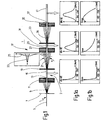
- FIG. 1 shows a briefly below as an energy filter device 1 designated ion beam energy filter device by a Ion beam 3 is traversed. This is achieved through a high-intensity, Pulsed laser beam 5 generated, which is on a target, here on a Converter film 7 hits. Heavy charged particles emerge from this 9, protons and heavier ions, from. The energy spectrum of the ion radiation comprising these particles 9 is for radiation therapy practically unusable, including the associated Range profile.
- a first collimator 11 is located at a distance from the converter film 7 a collimator opening 13 through which a collimated 15 beam with a wide spectrum and a strong low frequency Share exits. The outer part of the radiation is through the Collimator 11 is hidden.
- FIG. 1b schematic representation of the depth dose profile of the beam 15, the has the spectrum shown in Figure 1a.
- FIG. 1b the radiation dose is above the penetration depth z (units in mm) reproduced.
- Figure 1b clearly shows that the radiation dose decreases sharply with the depth of penetration.
- the collimated beam 15 now strikes the one downstream of the collimator 11 Energy filter device 1 and passes through it according to the figure 1 from left to right.
- the energy filter device 1 has a passive modulator 17, which in this exemplary embodiment is designed as a scatter filter. It comprises a first scattering film 19, which is arranged in the beam path, for example, at a distance of 50 cm from the collimator and on which the collimated beam 15 strikes.
- the beam is scattered by Coulomb interaction.
- relatively thin scatter foils for example 5 mm thick, are used, which consist of plexiglass, for example.
- the particles 9 passing through the first collimator 11, the impinging on the first scattering film 19, are thus scattered by this, with the smaller the energy, the greater the scatter the particle is 9.
- Figure 1c shows different distributions for the scattering angle ⁇ , where the first curve 23 the scattering for the high-energy Portion of the particles 9 in the scattered beam 21 and the second curve 25 the scattering for the low-energy part of the particles.
- the energy filter device 1 is at a distance from the first Scatter foil 19 arranged second collimator 27 with a collimator opening 29 with a diameter of 5 mm, for example, through which, according to the first curve 23, the majority of the high-energy Part of the particles 9 passes through and only a small one Share of low-energy particles.
- FIG. 1a The energy spectrum in FIG. 1a is below the hardened beam 31 of this beam 31 is shown. Among them can be found in figure 1b shows a schematic representation of the depth dose profile of the hardened Beam 31 with the energy spectrum shown in Figure 1a.
- FIG 1b clearly shows that the depth dose profile of the hardened Beam 31 differs from that of the collimated beam 15: the radiation dose the depth dose profile no longer drops so steeply over the penetration depth is therefore significantly flatter than with the collimated beam 15th
- the energy filter device 1 shown in FIG. 1 shows everything a first hardening stage on the first scattering film 19 and includes second collimator 27.
- Figure 1 also shows that the The embodiment of the energy filter device 1 shown here the passive modulator 17 has a second hardening stage, which a second one arranged at a distance from the second collimator 27 Scattering film 33 and one again at a distance from the second Scatter foil 33 arranged third collimator 35 with a collimator opening 37 includes.
- the hardened one Beam 31 passes through the second scattering film 33 Coulomb interaction scattered. Again, the loss of energy to keep low, a thin spreader is used, so that in turn a Gaussian distribution for the scattering angle ⁇ receives how it was dealt with above.
- the third collimator arranged after the second scattering film 35 in turn becomes the outer part of the scattered beam 39, as in the scattered beam 21, hidden.
- the collimator opening 37 there are significantly more high-energy particles than low-energy particles, so that a hardened Ray 41 results.
- this beam is shown here at about 200 MeV has a clear maximum, and in Figure 1b the depth dose profile of this beam with the spectrum shown in FIG. 1a.
- the effective dose of the beam also has increasing depth of penetration increases and after reaching a maximum, drops at a penetration depth of approx. 100 mm.
- the energy filter device 1 according to FIG. 1 has two hardening stages on. However, it is also conceivable to have more than two such stages use.
- the thickness of the scattering films 19, 23 and the size of the collimator openings 29, 37 and the distance between the scattering films and the Collimators 27, 35 are variable and based on the energy spectrum of the ion / proton beam entering the energy filter device tunable.
- the energy filter device 1 can the energy filter device 1 to the collimated beam 15 referred to as the primary beam.
- FIG. 2 shows a second embodiment of an energy filter device 1 ', which is traversed by an ion beam 3.
- a laser beam 5 which is incident on a target, here meets a converter film 7, a widely spread Ion beam with a wide spectrum is generated by particles 9 (protons and heavy ions) blasted out of the converter film 7 become.
- a first collimator is located at a distance from the converter film 7 11 with a collimator opening 13 through which part of the wide scattered proton beam occurs, creating a collimated beam 15 results.
- the energy spectrum is below this beam in FIG. 2a of this beam and the depth dose profile in FIG. 2b of this ray.
- the energy filter device 1 ' has a passive modulator 17' which comprises a magnetic filter 43 and an absorber 45.
- the magnetic filter 43 has a homogeneous magnetic field and is realized, for example, by an electromagnetic dipole.
- the collimated beam 15 runs through the magnetic field, so that a spectrally spread ion / proton beam 47 results.
- Figure 2 is the spread beam 47 fanned down, being high energy Particles are less deflected by the magnetic field than Particles with a lower energy and therefore a lower one Speed.
- the absorber 45 is introduced into the course of the spread beam 47, which is wedge-shaped, such that the top of the thicker part of the wedge is arranged and below the thinner. In order to the high-energy ions / protons pass through the thicker one Part and the low-energy part the thinner part of the absorber.
- the absorber is used for energy homogenization and one with it associated increase in transmission.
- the angle of the walls 49a, 49b arranged in a wedge shape relative to one another of the absorber 45 can be tailored to the desired energy loss become, when the spread beam 47 passes through the absorber 45 is desired. It is also possible to use the walls 49a and 49b, which run in a straight line here, i.e. lie in one plane, to form concave or convex in order to absorb energy to influence specifically.
- the absorber 45 is a second collimator 51 with a collimator opening 53 subordinate, which serves from the spread Beam 47, which has passed through the absorber 45, a desired Filter out the energy range.
- the beam emerging through the collimator opening 53 is by means of of a magnet 55 parallelized by a second, the first Magnetic field with opposite polarity is built up.
- a beam 57 results after passing through the second magnetic field with higher energy sharpness.
- the second and the lower collimator 51 Energy limit of the beam 47a influenced by the absorber 45 established.
- the magnetic field of the magnet 55 of the passive The now quasi-monoenergetic rays become modulators 17 ' parallelization.
- the parallelized one leaving the further magnetic filter 45 Beam 57 is through a suitable lens, here for example focused by a pair of quadrupoles 58. This will make a beam with a higher one Generates energy density.
- the advantage of the wedge-shaped absorber 45 is its high Transmission.
- the disadvantage is that the entire spectrum of the spread Beam 47 is shifted to lower energies.
- an energy filter device 1 'of the type described here can the proportion of intensity of the radiation above a desired one Energy lies on a desired one without significant loss of intensity Decelerate energy. With magnetic energy selection without a wedge-shaped absorber, only through a collimator this intensity component is lost. Such a filter would therefore show an unfavorable transmission curve.
- Figure 3 shows a third embodiment of an energy filter device 1 "through which an ion beam 3 passes.
- the ion beam is also used in the exemplary embodiment shown here produced by means of a laser 5, which is aimed at a target, here a converter film 7, strikes, so that charged particles from it 9, i.e. protons and heavy ions, can be blown out.
- the Converter film 7 is arranged after a first collimator 11, the one Collimator opening 13 through which a collimated beam 15th passes through, its energy spectrum in Figure 3a and its depth dose profile is shown in Figure 3b.
- This beam is fed to the energy filter device 1 ′′, the one passive modulator 17 ".
- the modulator 17 " has a non-linear filter, which a first magnetic filter 59 and a device 61 for Pruning the intensity of the individual energies of the beam having.
- the magnetic filter 59 has a preferably homogeneous magnetic field that collimated through the magnetic filter 59 Beam 15 spreads spectrally. According to Figure 3, the collimated Beam 15 fanned out downwards, being in the spread beam 63, as with the beam 47 according to FIG. 2, particles of high energy and thus higher speed a lower distraction than experience low energy particles.
- the charged particles 9 are in the first homogeneous magnetic field of the magnetic Filters 59 separated according to your energy and speed.
- the magnetic filter 59 is a second collimator 65 with a Collimator opening 67 downstream of the upper and lower energy limit of the spread beam 63 so that a beam 69 is produced.
- This beam 69 is parallelized by a magnet 71, whereby here a second magnetic field opposite to the first magnetic field is used and the beam is opposite to that in the first Magnetic filter 59 given direction is deflected.
- the parallelized beam 73 emerging from the magnet 71 has thus a higher energy sharpness than the spread beam 63.
- This parallelized beam 73 is cut by the device 61 the intensity of the individual energies, namely through one selective collimator so that the spatially according to energy separated beam portions can be trimmed to different extents and a filtered beam 77 is generated.
- Figure 3 is also a view seen in the beam direction of the selective Played collimator. That becomes clear here trained collimator opening 79, which is shown in the beam direction and has a wider free opening at the top than at the bottom.
- the collimator opening 79 tapers downwards in a wedge shape, whereby the course of the opening, in particular by means of a multi-leaf collimator 85 can be influenced particularly well to achieve the desired Obtain opening contour.
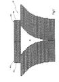
- a multi-leaf collimator 85 of the type mentioned here is shown in the figure 4, this figure showing a view of the collimator in FIG Reproduces the beam direction seen.
- the multi-leaf collimator shown here 85 is preferably designed as a multi-leaf collimator and has two adjacent groups 87a and 87b from thin slats 89a and 89b arranged in pairs, the motor can be adjusted.
- FIG. 4 shows that the top slats of the right and left Group 87a and 87b were moved towards each other and with touch their facing ends.
- Slats is a group of slats, the facing each other Ends are spaced from each other, wherein this distance decreases from top to bottom.
- the thickness of the slats, two of which are opposite each other Lamellae 89a and 89b are 2 - 4 mm.
- the perpendicular to the image plane given in FIG. 4, that is to say in the beam direction, measured slat depth is 5 - 10 cm, depending on the metal used in the manufacture of the slats.
- the magnet enters 71 leaving beam 73 through multi-leaf collimator 85.
- the beam runs vertically in the illustration according to FIG. 4 into the image plane selected here.
- the distance between the upper slats is greater than that of the ones below.
- the width of the collimator opening 91 across the beam direction and transverse to the deflection direction of the magnet 71 is larger for the high-energy part of the beam that is in the dipoles of the magnet 71 is only weakly distracted, and is getting smaller for the low-energy part of the beam 73, which is deflected more. Due to the movable slats 89a and 89b, the shape of the Collimator opening 91, here the taper given from top to bottom, be changed to the energy spectrum behind this to specify the particular collimator given the filtered beam 77.
- the spectrum of the beam 77 can be individually adapted in this way. It is thus possible to generate an energy spectrum which is in a depth dose profile with a high plateau (spread-out braggpeak) results. This is below the beam in FIGS. 3a and 3b 77 reproduced.
- the filtered beam 77 can be through a suitable lens, for example passed through a pair of quadrupoles 81 to a filtered and to obtain focused beam 83.
- the energy spectrum of the filtered beam 77 and in is in FIG. 3a Figure 3b shows its depth dose profile.
- FIGS. 1 to 3 of energy filter devices These have different passive modulators. In the exemplary embodiments described here were each a special type of modulator used. However, it is possible to see the different ones in the figures 1 to 3 shown modulators and their elements with each other to combine in order to optimally harden the ion beam 3 receive.
Landscapes
- Physics & Mathematics (AREA)
- Spectroscopy & Molecular Physics (AREA)
- Engineering & Computer Science (AREA)
- General Engineering & Computer Science (AREA)
- High Energy & Nuclear Physics (AREA)
- Radiation-Therapy Devices (AREA)
- Centrifugal Separators (AREA)
- Filtering Of Dispersed Particles In Gases (AREA)
Abstract
Description
- Figur 1
- eine schematische Darstellung einer Energiefiltereinrichtung;
- Figur 1a
- das Energiespektrum eines Ionen-/Protonenstrahls an verschiedenen Positionen der Energiefiltereinrichtung;
- Figur 1b
- das Tiefendosisprofil des Strahls an verschiedenen Stellen der Energiefiltereinrichtung;
- Figur 1c
- die Aufstreuung für den hochenergetischen und den niederenergetischen Anteil des Strahls in der Energiefiltereinrichtung;
- Figur 2
- eine Prinzipskizze eines weiteren Ausführungsbeispiels einer Energiefiltereinrichtung;
- Figur 2a
- das Energiespektrum eines Ionen-/Protonenstrahls an verschiedenen Positionen der Energiefiltereinrichtung;
- Figur 2b
- das Tiefendosisprofil des Strahls an verschiedenen Stellen der Energiefiltereinrichtung;
- Figur 3
- eine Prinzipskizze eines weiteren Ausführungsbeispiels einer Energiefiltereinrichtung und
- Figur 4
- einen Multi-Leaf-Kollimator in Strahlenrichtung gesehen.
Claims (21)
- Energiefiltereinrichtung für im Rahmen einer lonenstrahlentherapie verwendete Strahlen, gekennzeichnet durch mindestens einen der Aufhärtung der Strahlen dienenden passiven Modulator (17;17';17").
- Energiefiltereinrichtung nach Anspruch 1, dadurch gekennzeichnet, dass der Modulator (17) eine Streufolie (19) und einen im einem Abstand dazu angeordneten Kollimator (27) aufweist.
- Energiefiltereinrichtung nach Anspruch 2, dadurch gekennzeichnet, dass die Dicke der Streufolie (17), der Abstand zwischen Streufolie (17) und Kollimator (11) und/oder der Durchmesser der Kollimatoröffnung variabel sind.
- Energiefiltereinrichtung nach Anspruch 2 oder 3, dadurch gekennzeichnet, dass der Modulator mehrere hintereinander geschaltete Streufolien (19,33) mit zugeordneten Kollimatoren (27,35) aufweist.
- Energiefiltereinrichtung nach einem der vorhergehenden Ansprüche, dadurch gekennzeichnet, dass der Modulator (17') ein magnetisches Filter (43) und einen Absorber (45) aufweist.
- Energiefiltereinrichtung nach Anspruch 5, dadurch gekennzeichnet, dass der Absorber (45) dem magnetischen Filter (43) nachgeordnet ist.
- Energiefiltereinrichtung nach Anspruch 5 oder 6, dadurch gekennzeichnet, dass das Filter (43) ein homogenes Magnetfeld aufweist.
- Energiefiltereinrichtung nach einem der Ansprüche 5 bis 7, dadurch gekennzeichnet, dass ein elektromagnetischer Dipol zur Erzeugung des Magnetfelds verwendbar ist.
- Energiefiltereinrichtung nach einem der Ansprüche 5 bis 8, dadurch gekennzeichnet, dass der Absorber (45) eine inhomogene Dicke aufweist und keilförmig ausgebildet ist.
- Energiefiletereinrichtung nach einem der vorhergehenden Ansprüche 5 bis 9, dadurch gekennzeichnet, dass die Wände (49a, 49b) des Absorbers (45), die einen spitzen Winkel einschließen, gerade, also in einer gedachten Ebene, verlaufen.
- Energiefiltereinrichtung nach einem der vorhergehenden Ansprüche 5 bis 9, dadurch gekennzeichnet, dass die Wände (49a, 49b) des Absorbers (45), die einen spitzen Winkel einschließen, konkav oder konvex gewölbt sind.
- Energiefiltereinrichtung nach einem der vorhergehenden Ansprüche 5 bis 11, dadurch gekennzeichnet, dass der Absorber (45) so im Strahlverlauf angeordnet ist, dass Teilchen höherer Energie einen dickeren Bereich durchlaufen, als Teilchen niedrigerer Energie.
- Energiefiltereinrichtung nach einem der vorhergehenden Ansprüche 5 bis 12, dadurch gekennzeichnet, dass der Modulator (17') einen Magneten (55) aufweist, dessen Magnetfeld umgekehrt gepolt ist wie das Magnetfeld des magnetischen Filters (43).
- Energiefiltereinrichtung nach einem der vorhergehenden Ansprüche 5 bis 13, dadurch gekennzeichnet, dass vor dem zweiten Magnetfeld ein Kollimator (51) vorgesehen ist.
- Energiefiltereinrichtung nach einem der vorhergehenden Ansprüche, dadurch gekennzeichnet, dass der Modulator (17") ein nicht-lineares Filter aufweist, das ein erstes magnetisches Filter (59) zur Separation des Strahls nach der Energie der Teilchen und eine Vorrichtung (61) zur Beschneidung der Intensität der einzelnen Energien umfasst.
- Energiefiltereinrichtung nach Anspruch 15, dadurch gekennzeichnet, dass das magnetische Filter (59) ein erstes, vorzugsweise homogenes Magnetfeld aufweist.
- Energiefiltereinrichtung nach einem der vorhergehenden Ansprüche 15 bis 16, dadurch gekennzeichnet, dass der Modulator (17") einen Magneten (71) mit einem zweiten, vorzugsweise homogenen, Magnetfeld aufweist, das umgekehrt gepolt ist wie das erste Magnetfeld des magnetischen Filters (59).
- Energiefiltereinrichtung nach einem der vorhergehenden Ansprüche 15 bis 17, dadurch gekennzeichnet, dass dem Magneten (71) ein Kollimator (65) vorgeschaltet ist.
- Energiefiltereinrichtung nach einem der vorhergehenden Ansprüche 15 bis 18, dadurch gekennzeichnet, dass die Vorrichtung (61) zur Beschneidung der Intensität der einzelnen Energien einen Kollimator (75) mit veränderbarer Kollimatoröffnung (79) aufweist, wobei vorzugsweise die Durchlassbreite für die stärker abgelenkten Strahlanteile mit höherer Energie größer ist als die für die weniger stark abgelenkten niederenergetischen Strahlanteile.
- Energiefiltereinrichtung nach Anspruch 19, dadurch gekennzeichnet, dass der Kollimator (75) als Multi-Leaf-Kollimator auslegbar ist.
- Energiefiltereinrichtung nach einem der vorhergehenden Ansprüche, dadurch gekennzeichnet, dass die verschiedenen passiven Modulatoren (17;17';17") und deren Elemente miteinander kombinierbar sind.
Applications Claiming Priority (2)
| Application Number | Priority Date | Filing Date | Title |
|---|---|---|---|
| DE10323654A DE10323654A1 (de) | 2003-05-26 | 2003-05-26 | Energiefiltereinrichtung |
| DE10323654 | 2003-05-26 |
Publications (3)
| Publication Number | Publication Date |
|---|---|
| EP1482519A2 true EP1482519A2 (de) | 2004-12-01 |
| EP1482519A3 EP1482519A3 (de) | 2007-05-02 |
| EP1482519B1 EP1482519B1 (de) | 2010-12-29 |
Family
ID=33103589
Family Applications (1)
| Application Number | Title | Priority Date | Filing Date |
|---|---|---|---|
| EP04008939A Expired - Lifetime EP1482519B1 (de) | 2003-05-26 | 2004-04-15 | Energiefiltereinrichtung |
Country Status (4)
| Country | Link |
|---|---|
| US (1) | US7482605B2 (de) |
| EP (1) | EP1482519B1 (de) |
| AT (1) | ATE493738T1 (de) |
| DE (2) | DE10323654A1 (de) |
Cited By (4)
| Publication number | Priority date | Publication date | Assignee | Title |
|---|---|---|---|---|
| EP2016978A2 (de) | 2007-07-20 | 2009-01-21 | Siemens Aktiengesellschaft | Partikelstrahlapplikationsvorrichtung, Bestrahlungsvorrichtung sowie Verfahren zur Führung eines Partikelstrahls |
| EP2016979A3 (de) * | 2007-07-20 | 2009-06-24 | Siemens Aktiengesellschaft | Partikelstrahlapplikationsvorrichtung, Bestrahlungsvorrichtung sowie Verfahren zur Führung eines Partikelstrahls |
| WO2012062302A1 (de) * | 2010-09-16 | 2012-05-18 | Helmholtz-Zentrum Dresden - Rossendorf E. V. | Anordnung zur erzeugung hochenergetischer protonenstrahlen und deren verwendung |
| US20130256556A1 (en) * | 2010-12-13 | 2013-10-03 | Ingo Hofmann | Chromatic energy filter |
Families Citing this family (13)
| Publication number | Priority date | Publication date | Assignee | Title |
|---|---|---|---|---|
| CN101006541B (zh) * | 2003-06-02 | 2010-07-07 | 福克斯·彻斯癌症中心 | 高能多能离子选择系统、离子束治疗系统及离子束治疗中心 |
| CN101014383A (zh) * | 2003-12-02 | 2007-08-08 | 福克斯·彻斯癌症中心 | 调制用于放射治疗的激光-加速质子的方法 |
| US9006677B2 (en) * | 2007-02-27 | 2015-04-14 | Wisconsin Alumni Research Foundation | Fan beam modulator for ion beams providing continuous intensity modulation |
| DE102007014723A1 (de) * | 2007-03-23 | 2008-11-27 | Gesellschaft für Schwerionenforschung mbH (GSI) | Bestimmung eines Planungsvolumens für eine Bestrahlung eines Körpers |
| DE102007054919B4 (de) * | 2007-08-24 | 2009-07-30 | Gsi Helmholtzzentrum Für Schwerionenforschung Gmbh | Schnelle Regelung der Reichweite von hochenergetischen Ionenstrahlen für Präzisionsbestrahlungen von bewegten Zielvolumina |
| DE102008030699A1 (de) * | 2008-06-27 | 2009-12-31 | Siemens Aktiengesellschaft | Verfahren zur Energieüberprüfung eines Partikelstrahls, Vorrichtung zur Energieüberprüfung sowie Anlage hiermit |
| JP5374731B2 (ja) * | 2008-11-26 | 2013-12-25 | 独立行政法人日本原子力研究開発機構 | レーザー駆動粒子線照射装置およびレーザー駆動粒子線照射装置の動作方法 |
| DE102009040457B4 (de) * | 2009-08-27 | 2013-05-29 | Technische Universität Dresden | Einrichtung zur Selektion von Teilchen bestimmter Energie aus Teilchenstrahlen |
| ES2605031T3 (es) | 2009-10-23 | 2017-03-10 | Ion Beam Applications | Pórtico que comprende un analizador de haz para su uso en terapia de partículas |
| CN106298405B (zh) | 2012-01-31 | 2018-08-24 | 希尔应用医学有限公司 | 激光驱动离子束的激光激活磁场操纵 |
| US9999787B1 (en) * | 2017-03-08 | 2018-06-19 | Varian Medical Systems International Ag. | Beam limiting device for intensity modulated proton therapy |
| SE542451C2 (en) * | 2018-03-12 | 2020-05-05 | Ph Kleven As | Particle beam guiding system and related radiotherapy system |
| CN116884664B (zh) * | 2023-07-12 | 2024-03-01 | 上海交通大学 | 基于子群燃耗技术的稀缺同位素精细化能谱辐照生产方法 |
Citations (3)
| Publication number | Priority date | Publication date | Assignee | Title |
|---|---|---|---|---|
| JPH06154351A (ja) | 1992-11-19 | 1994-06-03 | Tsukuba Univ | 偏向静磁場による荷電重粒子線のビーム拡大装置 |
| US5440133A (en) | 1993-07-02 | 1995-08-08 | Loma Linda University Medical Center | Charged particle beam scattering system |
| WO2000049624A1 (de) | 1999-02-19 | 2000-08-24 | Gesellschaft für Schwerionenforschung mbH | Ionenstrahl-abtastsystem und verfahren zum betrieb des systems |
Family Cites Families (15)
| Publication number | Priority date | Publication date | Assignee | Title |
|---|---|---|---|---|
| US4672212A (en) * | 1985-02-28 | 1987-06-09 | Instrument Ab Scanditronax | Multi leaf collimator |
| DE3705295A1 (de) | 1987-02-19 | 1988-09-01 | Kernforschungsz Karlsruhe | Einrichtung zur tiefenabhaengigen implantation von teilchen in ein target |
| DE3705395A1 (de) | 1987-02-20 | 1988-09-08 | Ferrostaal Ag | Verfahren und anlage zur herstellung von winkelfoermigen oder u-foermigen handgriffbauteilen |
| US4845371A (en) * | 1988-03-29 | 1989-07-04 | Siemens Medical Laboratories, Inc. | Apparatus for generating and transporting a charged particle beam |
| EP1378266A1 (de) * | 1996-08-30 | 2004-01-07 | Hitachi, Ltd. | Vorrichtung zum Bestrahlen mit geladenen Teilchen |
| JPH1128252A (ja) * | 1997-07-11 | 1999-02-02 | Mitsubishi Electric Corp | 照射野の形成方法及び形成装置 |
| WO1999017865A1 (en) * | 1997-10-07 | 1999-04-15 | University Of Washington | Magnetic separator for linear dispersion and method for producing the same |
| US6118854A (en) * | 1998-10-06 | 2000-09-12 | Cardiac Mariners, Inc. | Method of making x-ray beam hardening filter and assembly |
| US6355383B1 (en) * | 1999-02-24 | 2002-03-12 | Nec Corporation | Electron-beam exposure system, a mask for electron-beam exposure and a method for electron-beam exposure |
| US6924493B1 (en) * | 1999-08-17 | 2005-08-02 | The Regents Of The University Of California | Ion beam lithography system |
| DE19952197C2 (de) | 1999-10-29 | 2002-01-31 | Siemens Ag | Takt- und Datenregenerator für unterschiedliche Datenraten |
| US6683320B2 (en) * | 2000-05-18 | 2004-01-27 | Fei Company | Through-the-lens neutralization for charged particle beam system |
| US6757355B1 (en) * | 2000-08-17 | 2004-06-29 | Siemens Medical Solutions Usa, Inc. | High definition radiation treatment with an intensity modulating multi-leaf collimator |
| US6639227B1 (en) * | 2000-10-18 | 2003-10-28 | Applied Materials, Inc. | Apparatus and method for charged particle filtering and ion implantation |
| JP4072359B2 (ja) * | 2002-02-28 | 2008-04-09 | 株式会社日立製作所 | 荷電粒子ビーム照射装置 |
-
2003
- 2003-05-26 DE DE10323654A patent/DE10323654A1/de not_active Ceased
-
2004
- 2004-04-15 AT AT04008939T patent/ATE493738T1/de active
- 2004-04-15 DE DE502004012041T patent/DE502004012041D1/de not_active Expired - Lifetime
- 2004-04-15 EP EP04008939A patent/EP1482519B1/de not_active Expired - Lifetime
- 2004-05-25 US US10/853,850 patent/US7482605B2/en not_active Expired - Fee Related
Patent Citations (3)
| Publication number | Priority date | Publication date | Assignee | Title |
|---|---|---|---|---|
| JPH06154351A (ja) | 1992-11-19 | 1994-06-03 | Tsukuba Univ | 偏向静磁場による荷電重粒子線のビーム拡大装置 |
| US5440133A (en) | 1993-07-02 | 1995-08-08 | Loma Linda University Medical Center | Charged particle beam scattering system |
| WO2000049624A1 (de) | 1999-02-19 | 2000-08-24 | Gesellschaft für Schwerionenforschung mbH | Ionenstrahl-abtastsystem und verfahren zum betrieb des systems |
Non-Patent Citations (3)
| Title |
|---|
| FOURKAL ET AL.: "Particle in cell simulation of laser-accelerated proton beams for radiation therapy", MED. PHYS., vol. 29, no. 12, December 2002 (2002-12-01), pages 2788 - 2798, XP012011681, DOI: doi:10.1118/1.1521122 |
| HERMANN WOLLNIK, OPTIC OF CHARGED PARTICLES", ACADEMIC EXPRESS, 1987, pages 253 - 277 |
| W.P. JONES ET AL.: "Design of a beam transport system for proton radiation therapy facility", PROCEEDINGS OF THE 1999 PARTICLE ACCELERATOR CONFERENCE, 1999, pages 2519 - 2521 |
Cited By (6)
| Publication number | Priority date | Publication date | Assignee | Title |
|---|---|---|---|---|
| EP2016978A2 (de) | 2007-07-20 | 2009-01-21 | Siemens Aktiengesellschaft | Partikelstrahlapplikationsvorrichtung, Bestrahlungsvorrichtung sowie Verfahren zur Führung eines Partikelstrahls |
| EP2016979A3 (de) * | 2007-07-20 | 2009-06-24 | Siemens Aktiengesellschaft | Partikelstrahlapplikationsvorrichtung, Bestrahlungsvorrichtung sowie Verfahren zur Führung eines Partikelstrahls |
| WO2012062302A1 (de) * | 2010-09-16 | 2012-05-18 | Helmholtz-Zentrum Dresden - Rossendorf E. V. | Anordnung zur erzeugung hochenergetischer protonenstrahlen und deren verwendung |
| US20130256556A1 (en) * | 2010-12-13 | 2013-10-03 | Ingo Hofmann | Chromatic energy filter |
| EP2652746A1 (de) * | 2010-12-13 | 2013-10-23 | GSI Helmholtzzentrum für Schwerionenforschung GmbH | Chromatisches energiefilter |
| US9390824B2 (en) | 2010-12-13 | 2016-07-12 | Gsi Helmholtzzentrum Fuer Schwerionenforschung Gmbh | Chromatic energy filter |
Also Published As
| Publication number | Publication date |
|---|---|
| ATE493738T1 (de) | 2011-01-15 |
| DE10323654A1 (de) | 2004-12-30 |
| US7482605B2 (en) | 2009-01-27 |
| EP1482519B1 (de) | 2010-12-29 |
| DE502004012041D1 (de) | 2011-02-10 |
| US20050029471A1 (en) | 2005-02-10 |
| EP1482519A3 (de) | 2007-05-02 |
Similar Documents
| Publication | Publication Date | Title |
|---|---|---|
| EP1482519B1 (de) | Energiefiltereinrichtung | |
| DE102009040031B4 (de) | Lasergetriebene Teilchenstrahl-Bestrahlungsvorrichtung sowie -Verfahren | |
| DE102007020599A1 (de) | Partikeltherapieanlage | |
| EP2100641B1 (de) | Partikeltherapieanlage und Verfahren zur Modulation eines in einem Beschleuniger erzeugten Partikelstrahls | |
| DE69931502T2 (de) | Kollimator für strahlentherapiegerät | |
| DE102007033894B3 (de) | Partikelstrahlapplikationsvorrichtung, Bestrahlungsvorrichtung sowie Verfahren zur Führung eines Partikelstrahls | |
| DE10060888A1 (de) | System und Verfahren zum Optimieren einer Strahlenbehandlung mit einem intensitätsmodulierten Mehr-Lamellen-Kollimator | |
| DE102009031772B4 (de) | Verfahren zur Bestimmung einer Wirkung eines Partikelstrahls in einem Material und Bestrahlungsverfahren und Bestrahlungsvorrichtung | |
| EP2087394A2 (de) | Vorrichtung zur homogenisierung von strahlung mit nicht regelmässigen mikrolinsenarrays | |
| DE10140100A1 (de) | Ein Verfahren zum Liefern von Strahlung von einer Strahlungsquelle an einen Behandlungsbereich | |
| DE3018914C2 (de) | Vorrichtung zum Bestrahlen eines begrenzten Volumens im Innern eines Körpers mit einer Strahlungsquelle | |
| DE1539659B2 (de) | Stigmatisches abbildungssystem fuer ein doppelfokussierendes massenspektrometer | |
| EP2175456A2 (de) | Röntgenanalyseinstrument mit verfahrbarem Aperturfenster | |
| DE2727161C2 (de) | Anordnung zur Aufstreuung von Elektronen für Elektronenbeschleuniger mit veränderbarer Beschleunigungsenergie | |
| EP3086325A1 (de) | Strahlführungssystem, teilchenstrahl-therapieanlage und verfahren | |
| WO2011012503A1 (de) | Optisches system zum erzeugen eines lichtstrahls zur behandlung eines substrats | |
| DE3734442A1 (de) | Verfahren und vorrichtung zur bestrahlung grosser flaechen mit ionen | |
| EP1872372A1 (de) | Laserbestrahlter hohlzylinder als linse für ionenstrahlen | |
| EP2247339A1 (de) | Teilchenstrahl-therapiesystem | |
| DE60030411T2 (de) | Optisches System zur Homogenisierung von Lichtstrahlen mit variablem Ausgangs-Querschnitt | |
| EP0182320A2 (de) | Verfahren zur Anbringung von Schnitten an biologischem Material | |
| EP0788610B1 (de) | Spektrometer für röntgenstrahlung | |
| DE2720514A1 (de) | Verfahren zur bestrahlung von kreiszylindrischen gegenstaenden mit beschleunigten elektronen | |
| EP2016978A2 (de) | Partikelstrahlapplikationsvorrichtung, Bestrahlungsvorrichtung sowie Verfahren zur Führung eines Partikelstrahls | |
| DE102015113010B3 (de) | Mehrfachspalt-Choppersystem zur Pulsformung eines Neutronenstrahls und Mehrfachspalt-Chopperscheibe zur Anwendung in einem Mehrfachspalt-Choppersystem |
Legal Events
| Date | Code | Title | Description |
|---|---|---|---|
| PUAI | Public reference made under article 153(3) epc to a published international application that has entered the european phase |
Free format text: ORIGINAL CODE: 0009012 |
|
| AK | Designated contracting states |
Kind code of ref document: A2 Designated state(s): AT BE BG CH CY CZ DE DK EE ES FI FR GB GR HU IE IT LI LU MC NL PL PT RO SE SI SK TR |
|
| AX | Request for extension of the european patent |
Extension state: AL HR LT LV MK |
|
| RIC1 | Information provided on ipc code assigned before grant |
Ipc: A61N 5/10 20060101ALN20060911BHEP Ipc: G21K 1/02 20060101ALI20060911BHEP Ipc: G21K 1/10 20060101AFI20040901BHEP |
|
| PUAL | Search report despatched |
Free format text: ORIGINAL CODE: 0009013 |
|
| AK | Designated contracting states |
Kind code of ref document: A3 Designated state(s): AT BE BG CH CY CZ DE DK EE ES FI FR GB GR HU IE IT LI LU MC NL PL PT RO SE SI SK TR |
|
| AX | Request for extension of the european patent |
Extension state: AL HR LT LV MK |
|
| RIC1 | Information provided on ipc code assigned before grant |
Ipc: A61N 5/10 20060101ALN20060911BHEP Ipc: H01J 49/46 20060101ALI20070328BHEP Ipc: G21K 1/02 20060101ALI20070328BHEP Ipc: G21K 1/10 20060101AFI20040901BHEP |
|
| 17P | Request for examination filed |
Effective date: 20071013 |
|
| 17Q | First examination report despatched |
Effective date: 20071127 |
|
| AKX | Designation fees paid |
Designated state(s): AT BE BG CH CY CZ DE DK EE ES FI FR GB GR HU IE IT LI LU MC NL PL PT RO SE SI SK TR |
|
| RAP1 | Party data changed (applicant data changed or rights of an application transferred) |
Owner name: GSI HELMHOLTZZENTRUM FUER SCHWERIONENFORSCHUNG GMB |
|
| GRAP | Despatch of communication of intention to grant a patent |
Free format text: ORIGINAL CODE: EPIDOSNIGR1 |
|
| GRAS | Grant fee paid |
Free format text: ORIGINAL CODE: EPIDOSNIGR3 |
|
| GRAA | (expected) grant |
Free format text: ORIGINAL CODE: 0009210 |
|
| AK | Designated contracting states |
Kind code of ref document: B1 Designated state(s): AT BE BG CH CY CZ DE DK EE ES FI FR GB GR HU IE IT LI LU MC NL PL PT RO SE SI SK TR |
|
| REG | Reference to a national code |
Ref country code: GB Ref legal event code: FG4D Free format text: NOT ENGLISH |
|
| REG | Reference to a national code |
Ref country code: CH Ref legal event code: EP |
|
| REG | Reference to a national code |
Ref country code: IE Ref legal event code: FG4D Free format text: LANGUAGE OF EP DOCUMENT: GERMAN |
|
| REF | Corresponds to: |
Ref document number: 502004012041 Country of ref document: DE Date of ref document: 20110210 Kind code of ref document: P |
|
| REG | Reference to a national code |
Ref country code: DE Ref legal event code: R096 Ref document number: 502004012041 Country of ref document: DE Effective date: 20110210 |
|
| REG | Reference to a national code |
Ref country code: NL Ref legal event code: VDEP Effective date: 20101229 |
|
| PG25 | Lapsed in a contracting state [announced via postgrant information from national office to epo] |
Ref country code: BG Free format text: LAPSE BECAUSE OF FAILURE TO SUBMIT A TRANSLATION OF THE DESCRIPTION OR TO PAY THE FEE WITHIN THE PRESCRIBED TIME-LIMIT Effective date: 20110329 Ref country code: FI Free format text: LAPSE BECAUSE OF FAILURE TO SUBMIT A TRANSLATION OF THE DESCRIPTION OR TO PAY THE FEE WITHIN THE PRESCRIBED TIME-LIMIT Effective date: 20101229 Ref country code: SE Free format text: LAPSE BECAUSE OF FAILURE TO SUBMIT A TRANSLATION OF THE DESCRIPTION OR TO PAY THE FEE WITHIN THE PRESCRIBED TIME-LIMIT Effective date: 20101229 Ref country code: SI Free format text: LAPSE BECAUSE OF FAILURE TO SUBMIT A TRANSLATION OF THE DESCRIPTION OR TO PAY THE FEE WITHIN THE PRESCRIBED TIME-LIMIT Effective date: 20101229 Ref country code: CY Free format text: LAPSE BECAUSE OF FAILURE TO SUBMIT A TRANSLATION OF THE DESCRIPTION OR TO PAY THE FEE WITHIN THE PRESCRIBED TIME-LIMIT Effective date: 20101229 |
|
| REG | Reference to a national code |
Ref country code: IE Ref legal event code: FD4D |
|
| PG25 | Lapsed in a contracting state [announced via postgrant information from national office to epo] |
Ref country code: PT Free format text: LAPSE BECAUSE OF FAILURE TO SUBMIT A TRANSLATION OF THE DESCRIPTION OR TO PAY THE FEE WITHIN THE PRESCRIBED TIME-LIMIT Effective date: 20110429 Ref country code: CZ Free format text: LAPSE BECAUSE OF FAILURE TO SUBMIT A TRANSLATION OF THE DESCRIPTION OR TO PAY THE FEE WITHIN THE PRESCRIBED TIME-LIMIT Effective date: 20101229 Ref country code: ES Free format text: LAPSE BECAUSE OF FAILURE TO SUBMIT A TRANSLATION OF THE DESCRIPTION OR TO PAY THE FEE WITHIN THE PRESCRIBED TIME-LIMIT Effective date: 20110409 Ref country code: GR Free format text: LAPSE BECAUSE OF FAILURE TO SUBMIT A TRANSLATION OF THE DESCRIPTION OR TO PAY THE FEE WITHIN THE PRESCRIBED TIME-LIMIT Effective date: 20110330 Ref country code: EE Free format text: LAPSE BECAUSE OF FAILURE TO SUBMIT A TRANSLATION OF THE DESCRIPTION OR TO PAY THE FEE WITHIN THE PRESCRIBED TIME-LIMIT Effective date: 20101229 |
|
| PG25 | Lapsed in a contracting state [announced via postgrant information from national office to epo] |
Ref country code: SK Free format text: LAPSE BECAUSE OF FAILURE TO SUBMIT A TRANSLATION OF THE DESCRIPTION OR TO PAY THE FEE WITHIN THE PRESCRIBED TIME-LIMIT Effective date: 20101229 Ref country code: PL Free format text: LAPSE BECAUSE OF FAILURE TO SUBMIT A TRANSLATION OF THE DESCRIPTION OR TO PAY THE FEE WITHIN THE PRESCRIBED TIME-LIMIT Effective date: 20101229 Ref country code: RO Free format text: LAPSE BECAUSE OF FAILURE TO SUBMIT A TRANSLATION OF THE DESCRIPTION OR TO PAY THE FEE WITHIN THE PRESCRIBED TIME-LIMIT Effective date: 20101229 Ref country code: NL Free format text: LAPSE BECAUSE OF FAILURE TO SUBMIT A TRANSLATION OF THE DESCRIPTION OR TO PAY THE FEE WITHIN THE PRESCRIBED TIME-LIMIT Effective date: 20101229 |
|
| BERE | Be: lapsed |
Owner name: GSI HELMHOLTZZENTRUM FUR SCHWERIONENFORSCHUNG G.M. Effective date: 20110430 |
|
| PG25 | Lapsed in a contracting state [announced via postgrant information from national office to epo] |
Ref country code: IE Free format text: LAPSE BECAUSE OF FAILURE TO SUBMIT A TRANSLATION OF THE DESCRIPTION OR TO PAY THE FEE WITHIN THE PRESCRIBED TIME-LIMIT Effective date: 20101229 Ref country code: DK Free format text: LAPSE BECAUSE OF FAILURE TO SUBMIT A TRANSLATION OF THE DESCRIPTION OR TO PAY THE FEE WITHIN THE PRESCRIBED TIME-LIMIT Effective date: 20101229 |
|
| PLBE | No opposition filed within time limit |
Free format text: ORIGINAL CODE: 0009261 |
|
| STAA | Information on the status of an ep patent application or granted ep patent |
Free format text: STATUS: NO OPPOSITION FILED WITHIN TIME LIMIT |
|
| PG25 | Lapsed in a contracting state [announced via postgrant information from national office to epo] |
Ref country code: MC Free format text: LAPSE BECAUSE OF NON-PAYMENT OF DUE FEES Effective date: 20110430 |
|
| REG | Reference to a national code |
Ref country code: CH Ref legal event code: PL |
|
| 26N | No opposition filed |
Effective date: 20110930 |
|
| REG | Reference to a national code |
Ref country code: DE Ref legal event code: R097 Ref document number: 502004012041 Country of ref document: DE Effective date: 20110930 |
|
| PG25 | Lapsed in a contracting state [announced via postgrant information from national office to epo] |
Ref country code: LI Free format text: LAPSE BECAUSE OF NON-PAYMENT OF DUE FEES Effective date: 20110430 Ref country code: BE Free format text: LAPSE BECAUSE OF NON-PAYMENT OF DUE FEES Effective date: 20110430 Ref country code: CH Free format text: LAPSE BECAUSE OF NON-PAYMENT OF DUE FEES Effective date: 20110430 |
|
| PG25 | Lapsed in a contracting state [announced via postgrant information from national office to epo] |
Ref country code: IT Free format text: LAPSE BECAUSE OF FAILURE TO SUBMIT A TRANSLATION OF THE DESCRIPTION OR TO PAY THE FEE WITHIN THE PRESCRIBED TIME-LIMIT Effective date: 20101229 |
|
| REG | Reference to a national code |
Ref country code: AT Ref legal event code: MM01 Ref document number: 493738 Country of ref document: AT Kind code of ref document: T Effective date: 20110415 |
|
| PG25 | Lapsed in a contracting state [announced via postgrant information from national office to epo] |
Ref country code: AT Free format text: LAPSE BECAUSE OF NON-PAYMENT OF DUE FEES Effective date: 20110415 |
|
| PG25 | Lapsed in a contracting state [announced via postgrant information from national office to epo] |
Ref country code: LU Free format text: LAPSE BECAUSE OF NON-PAYMENT OF DUE FEES Effective date: 20110415 |
|
| PG25 | Lapsed in a contracting state [announced via postgrant information from national office to epo] |
Ref country code: TR Free format text: LAPSE BECAUSE OF FAILURE TO SUBMIT A TRANSLATION OF THE DESCRIPTION OR TO PAY THE FEE WITHIN THE PRESCRIBED TIME-LIMIT Effective date: 20101229 |
|
| PG25 | Lapsed in a contracting state [announced via postgrant information from national office to epo] |
Ref country code: HU Free format text: LAPSE BECAUSE OF FAILURE TO SUBMIT A TRANSLATION OF THE DESCRIPTION OR TO PAY THE FEE WITHIN THE PRESCRIBED TIME-LIMIT Effective date: 20101229 |
|
| REG | Reference to a national code |
Ref country code: DE Ref legal event code: R082 Ref document number: 502004012041 Country of ref document: DE |
|
| REG | Reference to a national code |
Ref country code: FR Ref legal event code: PLFP Year of fee payment: 13 |
|
| PGFP | Annual fee paid to national office [announced via postgrant information from national office to epo] |
Ref country code: GB Payment date: 20160921 Year of fee payment: 13 |
|
| PGFP | Annual fee paid to national office [announced via postgrant information from national office to epo] |
Ref country code: FR Payment date: 20160922 Year of fee payment: 13 |
|
| GBPC | Gb: european patent ceased through non-payment of renewal fee |
Effective date: 20170415 |
|
| REG | Reference to a national code |
Ref country code: FR Ref legal event code: ST Effective date: 20171229 |
|
| PG25 | Lapsed in a contracting state [announced via postgrant information from national office to epo] |
Ref country code: FR Free format text: LAPSE BECAUSE OF NON-PAYMENT OF DUE FEES Effective date: 20170502 |
|
| PG25 | Lapsed in a contracting state [announced via postgrant information from national office to epo] |
Ref country code: GB Free format text: LAPSE BECAUSE OF NON-PAYMENT OF DUE FEES Effective date: 20170415 |
|
| PGFP | Annual fee paid to national office [announced via postgrant information from national office to epo] |
Ref country code: DE Payment date: 20210421 Year of fee payment: 18 |
|
| REG | Reference to a national code |
Ref country code: DE Ref legal event code: R119 Ref document number: 502004012041 Country of ref document: DE |
|
| PG25 | Lapsed in a contracting state [announced via postgrant information from national office to epo] |
Ref country code: DE Free format text: LAPSE BECAUSE OF NON-PAYMENT OF DUE FEES Effective date: 20221103 |