EP1481938A1 - Greifer für das Heben von Lasten mit umgreifbaren Tragprofilen - Google Patents
Greifer für das Heben von Lasten mit umgreifbaren Tragprofilen Download PDFInfo
- Publication number
- EP1481938A1 EP1481938A1 EP03012347A EP03012347A EP1481938A1 EP 1481938 A1 EP1481938 A1 EP 1481938A1 EP 03012347 A EP03012347 A EP 03012347A EP 03012347 A EP03012347 A EP 03012347A EP 1481938 A1 EP1481938 A1 EP 1481938A1
- Authority
- EP
- European Patent Office
- Prior art keywords
- gripper
- pressure
- cylinder
- piston
- tongs
- Prior art date
- Legal status (The legal status is an assumption and is not a legal conclusion. Google has not performed a legal analysis and makes no representation as to the accuracy of the status listed.)
- Granted
Links
- 239000012530 fluid Substances 0.000 claims description 6
- 230000008878 coupling Effects 0.000 claims description 4
- 238000010168 coupling process Methods 0.000 claims description 4
- 238000005859 coupling reaction Methods 0.000 claims description 4
- 210000003746 feather Anatomy 0.000 description 4
- 238000000034 method Methods 0.000 description 4
- 125000006850 spacer group Chemical group 0.000 description 2
- 238000011161 development Methods 0.000 description 1
- 230000018109 developmental process Effects 0.000 description 1
- 238000005553 drilling Methods 0.000 description 1
- 239000007787 solid Substances 0.000 description 1
Images

Classifications
-
- B—PERFORMING OPERATIONS; TRANSPORTING
- B66—HOISTING; LIFTING; HAULING
- B66C—CRANES; LOAD-ENGAGING ELEMENTS OR DEVICES FOR CRANES, CAPSTANS, WINCHES, OR TACKLES
- B66C1/00—Load-engaging elements or devices attached to lifting or lowering gear of cranes or adapted for connection therewith for transmitting lifting forces to articles or groups of articles
- B66C1/10—Load-engaging elements or devices attached to lifting or lowering gear of cranes or adapted for connection therewith for transmitting lifting forces to articles or groups of articles by mechanical means
- B66C1/62—Load-engaging elements or devices attached to lifting or lowering gear of cranes or adapted for connection therewith for transmitting lifting forces to articles or groups of articles by mechanical means comprising article-engaging members of a shape complementary to that of the articles to be handled
- B66C1/64—Load-engaging elements or devices attached to lifting or lowering gear of cranes or adapted for connection therewith for transmitting lifting forces to articles or groups of articles by mechanical means comprising article-engaging members of a shape complementary to that of the articles to be handled for T- or I-section beams or girders
-
- B—PERFORMING OPERATIONS; TRANSPORTING
- B66—HOISTING; LIFTING; HAULING
- B66C—CRANES; LOAD-ENGAGING ELEMENTS OR DEVICES FOR CRANES, CAPSTANS, WINCHES, OR TACKLES
- B66C1/00—Load-engaging elements or devices attached to lifting or lowering gear of cranes or adapted for connection therewith for transmitting lifting forces to articles or groups of articles
- B66C1/10—Load-engaging elements or devices attached to lifting or lowering gear of cranes or adapted for connection therewith for transmitting lifting forces to articles or groups of articles by mechanical means
- B66C1/42—Gripping members engaging only the external or internal surfaces of the articles
- B66C1/425—Gripping members engaging only the external or internal surfaces of the articles motor actuated
- B66C1/427—Gripping members engaging only the external or internal surfaces of the articles motor actuated by hydraulic or pneumatic motors
Definitions
- the invention relates to a gripper for lifting loads with graspable Support profiles, consisting of a carrier and at least one on it guided and held gripper, the carrier with means for coupling on the lifting device and with holding pins for closing and lifting the Gripper tongs and the gripper tongs with a swivel bearing against each other pivotable pliers legs are equipped and the gripper means assigned to secure the closed position of the gripper in the loaded state are.
- a gripper for lifting devices has become known from DE 93 18 652.5 U1, which is equipped with a carrier and with two gripper tongs.
- the carrier on the one hand has a central coupling element for attacking a crane hook and on the other hand, a pin bearing called a support pin for carrying and Closing the gripper tongs.
- the pin bearing consists of a retaining bolt that is in the direction of stroke against each other inclined scenes of the pliers legs of the gripper tongs engages.
- the Pliers legs are held together by means of a central swivel bearing are guided in this area on the beam in the vertical direction.
- the gripper tongs When lifting the support bolt of the carrier, the gripper tongs first closed. When the gripper tongs are in the closed position, they become lifted as a unit together with the load. To prevent the opening of the Pliers under load are lifted between the retaining bolts of the Carrier and the pivot bearing of the pliers legs manually a spacer pivoted in and secured in this pivoted position. Subsequently the lifting process begins.
- This gripper has proven itself in use and ensures one adequate safety even when lifting heavy objects, e.g. B. longer Rail sections for railroad tracks.
- the spacer - so it is inserted - cannot be reached when the load is lifted and cannot be manipulated.
- the gripper tongs are opened and closed only when the gripper is removed Load and regularly manually.
- the use of the gripper and its gripper tongs in the area of longer transport routes makes for opening and closing
- the gripper tongs can be used by up to two people at the respective location required.
- Cylinder-piston systems are common for such work operations Pressure rooms from a central control panel via appropriate pressure lines can optionally be pressurized.
- the object of the present invention is to provide a gripper at which the opening and closing of the gripper with a power-operated Drive is executable and the opening of the gripper tongs independently of one erroneous behavior of the operating personnel with the load still attached is excluded is.
- the manner in which the opening device is acted upon by force leads automatically that the opening process is associated with the lifting of the load. is If the load is too large, the opening process cannot be carried out. The assigned force limiter prevents this.
- the encompassing the support profile Forceps legs cannot be moved as far with the available force, that they share the profile.
- the gripper tongs can be used with the available force open freely.
- Actuating means provides a cylinder-piston system, in its pressure line a pressure relief valve is inserted.
- a railroad track is used as a load with a support profile that can be gripped around 3 described.
- the grippers can also be used for other loads in the grip area equipped with gripping support profiles are.
- Such loops of ropes can also be such support profiles.
- the gripper consists of a carrier 1, which has a central coupling element, the clutch 11 is provided. Retaining rings, Loops or the crane hook of the hoist can be attached.
- the carrier 1 aligned parallel to the rails 3 to be carried is on provided at both ends with bearing sections 13, 13 ', each one Guide retaining pin 12, 12 '.
- the holding pins 12, 12 ' reach through the scenes 211, 221 of the pliers legs 21, 21 'and 22, 22' of the gripper tongs 2, 2 '.
- the outer ends of the shaft of the pivot bearing 20 are in a guide groove 14, 14 ', which is preferably oriented vertically, guided laterally, so that swinging around the holding pins 12, 12 'is avoided.
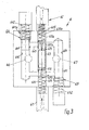
- a cylinder-piston system 5 is arranged in the middle area of the gripper, the cylinder 51 is held by means of attachment 15 to the carrier during the Piston 52 with its piston rod 520 engages around the shaft of the pivot bearing 20.
- Pressure spaces 53, 54 form within the cylinder-piston system 5.
- the pressure chamber 53 is for closing the gripper tongs 2, 2 'and the pressure chamber 54 responsible for opening the gripper tongs 2, 2 '.
- Both pressure rooms 53, 54 are connected to valve unit 6 via connections 66 and 67, respectively.
- This valve unit 6 is via the connections 61 and 62 and corresponding Pressure hoses connected to a pressure source by a central one Control panel, e.g. B. the cabin of the crane can be pressurized.
- a central one Control panel e.g. B. the cabin of the crane can be pressurized.
- Valve unit 6 shown schematically in FIG. 3 with a control piston 63 and corresponding pressure relief valves 64, 65 equipped.
- a bore 633 extends between the connections 61 and 62, in which a control piston can move axially positively.
- the control piston 63 is in a central position by means of springs 634, 635 (solid lines) held. In the middle position, it closes channels 643, 653.
- the cylinder-piston system 5 is in a secured rest position.
- the control piston 63 is provided with two annular grooves 631, 632, which over a Hole system each connected to one of the end faces of the control piston 63 are.
- valve unit Bores 644, 654 arranged in which the pistons 641, 651 of the pressure relief valves 64, 65 are performed. These pistons 641, 651 are by means of Springs 642, 652 held in the closed position.
- the holes 644, 654 are over ports 66 and 67 connected to pressure chambers 54 and 53, respectively.
- control piston 63 moves from the central position into the position 63a (dotted).
- the annular groove 631 is in the position 631a brought. This allows hydraulic fluid to flow out of channel 643 via the ring groove Drain 631a in the direction of connection 62.
- connection 61 Pressure A supply of hydraulic fluid takes place via the connection 61 Pressure, the hydraulic fluid flows below the control piston 63a into the left section of channel 653 and into hole 644. Via the connection The pressure chamber 54 of the cylinder-piston unit 5 becomes 66 with this pressure applied.
- the pressure relief valve 64 active. If the pressure in bore 644 exceeds a certain size, there the piston 641 overcoming the spring force of the spring 642 the channel 643 free.
- the pressure can be via the annular groove 631a of the control piston 63a and that Relax the corresponding bore system via connection 62.
- the pressure in the pressure chamber 54 is adjusted so that the pivot bearing 20 cannot be moved upwards when the load is attached. Only, if the rail or any other corresponding, reachable load is on on a solid surface, you can use the available pressure in the Pressure chamber 54 raised the shaft of the pivot bearing and the gripper tongs 2 and 2 'are opened. There are no additional ones for this opening process Assistants required.
Landscapes
- Engineering & Computer Science (AREA)
- Mechanical Engineering (AREA)
- Load-Engaging Elements For Cranes (AREA)
- Forklifts And Lifting Vehicles (AREA)
Abstract
Description
- Fig. 1
- eine Ansicht des Greifers mit schematisch dargestellter Zylinder-Kolben-Einheit für das Öffnen und Schließen der Greiferzangen,
- Fig. 2
- eine schematische Darstellung einer Greiferzange und der Zuordnung des Öffnungs- und/oder Schließmechanismus und
- Fig. 3
- eine schematische Schnittdarstellung durch die Ventileinheit mit Steuerkolben und Druckbegrenzungsventilen für das Öffnen und Schließen von Greiferzangen.
- 1
- Träger
- 11
- Kupplung
- 12, 12'
- Haltezapfen
- 13, 13'
- Lagerabschnitt
- 14, 14'
- Führungsnut
- 15
- Befestigung (Zylinder)
- 2, 2'
- Greiferzange
- 20
- Schwenklager/Welle
- 21, 21'
- Zangenschenkel
- 211
- Kulisse
- 22, 22'
- Zangenschenkel
- 221
- Kulisse
- 3
- Schiene
- 4
- Schlaufe/Hubmttel (auch Kranhaken)
- 5
- Zylinder-Kolben-System/Stellmittel
- 51
- Zylinder
- 52
- Kolben
- 520
- Kolbenstange
- 53
- Druckraum (Schließen)
- 54
- Druckraum (Öffnen)
- 6
- Ventileinheit
- 61
- Druckanschluss (Öffnen)
- 62
- Druckanschluss (Schließen)
- 63
- Steuerkolben (Mittelstellung)
- 63a
- Steuerkolben (Position Öffnen)
- 631
- Ringnut
- 631a
- Ringnut (Öffnen)
- 632
- Ringnut
- 633
- Bohrung
- 634
- Feder
- 635
- Feder
- 64
- Druckbegrenzungsventil
- 641
- Kolben
- 641a
- Kolben (Überlastposition)
- 642
- Feder
- 643
- Kanal
- 644
- Zylinderbohrung
- 65
- Druckbegrenzungsventil
- 651
- Kolben
- 652
- Feder
- 653
- Kanal
- 66
- Anschluss (Ausgang zum Druckraum 54)
- 67
- Anschluss (Ausgang zum Druckraum 53)
Claims (5)
- Greifer für das Heben von Lasten mit umgreifbaren Tragprofilen, bestehend aus einem Träger (1) und aus mindestens einer daran geführten und gehaltenen Greiferzange (2),
wobei der Träger (1) mit Mitteln (11) zur Kopplung an dem Hubgerät und mit einem Hublager (Haltezapfen 12) für das Schließen und Heben der Greiferzange (2) ausgestattet ist,
wobei die Greiferzange (2) mit um ein Schwenklager (20) gegeneinander schwenkbaren, den Schienenkopf umgreifenden Zangenschenkeln (21, 22) ausgestattet ist und
wobei dem Greifer Mittel zum Sichern der Schließstellung der Greiferzange (2) im Belastungszustand zugeordnet sind,
dadurch gekennzeichnet, dass zwischen dem Träger (1) und dem Schwenklager (20) der Greiferzange (2, 2') kraftgesteuerte Stellmittel (Zylinder-Kolben-System 5) zum Öffnen und Schließen der Greiferzange (2, 2') angeordnet sind und
dass dem Stellmittel (5) am Greifer befindliche Begrenzer (z. B. Druckbegrenzungsventil 64) für die Antriebskraft zugeordnet sind. - Greifer nach Anspruch 1, dadurch gekennzeichnet, dass das Stellmittel ein Zylinder-Kolben-System (5) ist, dessen Druckräume (53, 54) über getrennte Anschlüsse (61, 62) und Druckleitungen von einem zentralen Bedienraum steuerbar sind, und
dass mindestens dem Druckraum (54) für das Öffnen der Greiferzange (2, 2') ein Druckbegrenzungsventil (64, 65) zugeordnet ist. - Greifer nach Anspruch 1 und 2, dadurch gekennzeichnet, dass das Druckmedium des Zylinder-Kolben-Systems (5) eine Hydraulikflüssigkeit ist.
- Greifer nach Anspruch 1 bis 3, dadurch gekennzeichnet, dass am Greifer eine Ventileinheit (6) befestigt ist,
dass die Ventileinheit (6) je einen Anschluss (61, 62) für je eine Druckleitung zum Öffnen und Schließen aufweist, die von einer zentralen Steuereinheit bedienbar sind,
dass die Ventileinheit (6) Anschlüsse (66, 67) für beide Druckräume (53, 54) des Zylinder-Kolben-Systems (5) aufweist und
dass die Ventileinheit (6) mit einem Steuerkolben (63) und mit zwei Druckbegrenzungsventilen (64, 65) ausgestattet ist. - Greifer nach Anspruch 4, dadurch gekennzeichnet, dass der Steuerkolben (63) koaxial und axial beweglich in einer Bohrung (633) zwischen dem Anschluss (61) der Druckleitung für das Öffnen und dem Anschluss (62) der Druckleitung für das Schließen mittels Federn (634, 635) elastisch in einer Mittelstellung gehalten ist,
dass der Steuerkolben (63) der Mittelstellung beide Druckräume (53, 54) des Zylinder-Kolben-Systems (5) geschlossen hält,
dass dem Steuerkolben (63) beiderseits der Mittelstellung je ein aktivierbarer Kanal (643, 653; Bohrung 644, 654; Anschluss 66, 67) mit Verbindung zu einem der Druckräume (53, 54) des Zylinder-Kolben-Systems (5) zugeordnet ist und
dass jeweils in diesem Kanal (643, 653; Bohrung 644, 654; Anschluss 66, 67) und in dem jeweiligen Druckraum (53, 54) je ein Druckbegrenzungsventil
Priority Applications (3)
| Application Number | Priority Date | Filing Date | Title |
|---|---|---|---|
| EP03012347A EP1481938B1 (de) | 2003-05-30 | 2003-05-30 | Greifer für das Heben von Lasten mit umgreifbaren Tragprofilen |
| DE50308407T DE50308407D1 (de) | 2003-05-30 | 2003-05-30 | Greifer für das Heben von Lasten mit umgreifbaren Tragprofilen |
| AT03012347T ATE375955T1 (de) | 2003-05-30 | 2003-05-30 | Greifer für das heben von lasten mit umgreifbaren tragprofilen |
Applications Claiming Priority (1)
| Application Number | Priority Date | Filing Date | Title |
|---|---|---|---|
| EP03012347A EP1481938B1 (de) | 2003-05-30 | 2003-05-30 | Greifer für das Heben von Lasten mit umgreifbaren Tragprofilen |
Publications (2)
| Publication Number | Publication Date |
|---|---|
| EP1481938A1 true EP1481938A1 (de) | 2004-12-01 |
| EP1481938B1 EP1481938B1 (de) | 2007-10-17 |
Family
ID=33104112
Family Applications (1)
| Application Number | Title | Priority Date | Filing Date |
|---|---|---|---|
| EP03012347A Expired - Lifetime EP1481938B1 (de) | 2003-05-30 | 2003-05-30 | Greifer für das Heben von Lasten mit umgreifbaren Tragprofilen |
Country Status (3)
| Country | Link |
|---|---|
| EP (1) | EP1481938B1 (de) |
| AT (1) | ATE375955T1 (de) |
| DE (1) | DE50308407D1 (de) |
Citations (3)
| Publication number | Priority date | Publication date | Assignee | Title |
|---|---|---|---|---|
| GB862948A (en) * | 1958-08-27 | 1961-03-15 | New York Air Brake Co | Improvements in or relating to two-way fluid pressure relief valves |
| GB1057778A (en) * | 1963-06-12 | 1967-02-08 | Fives Lille Cail | Improvements in slab tongs |
| DE9318652U1 (de) * | 1993-12-07 | 1994-06-23 | Glumann, Karl, 09127 Chemnitz | Greifer für Hubgeräte zum Heben von stangenförmigen Körpern, insbesondere von Eisenbahnschienen |
-
2003
- 2003-05-30 EP EP03012347A patent/EP1481938B1/de not_active Expired - Lifetime
- 2003-05-30 DE DE50308407T patent/DE50308407D1/de not_active Expired - Lifetime
- 2003-05-30 AT AT03012347T patent/ATE375955T1/de active
Patent Citations (3)
| Publication number | Priority date | Publication date | Assignee | Title |
|---|---|---|---|---|
| GB862948A (en) * | 1958-08-27 | 1961-03-15 | New York Air Brake Co | Improvements in or relating to two-way fluid pressure relief valves |
| GB1057778A (en) * | 1963-06-12 | 1967-02-08 | Fives Lille Cail | Improvements in slab tongs |
| DE9318652U1 (de) * | 1993-12-07 | 1994-06-23 | Glumann, Karl, 09127 Chemnitz | Greifer für Hubgeräte zum Heben von stangenförmigen Körpern, insbesondere von Eisenbahnschienen |
Also Published As
| Publication number | Publication date |
|---|---|
| ATE375955T1 (de) | 2007-11-15 |
| EP1481938B1 (de) | 2007-10-17 |
| DE50308407D1 (de) | 2007-11-29 |
Similar Documents
| Publication | Publication Date | Title |
|---|---|---|
| EP1369598B2 (de) | Elektrohydraulische Hubsteuervorrichtung für Flurförderfahrzeuge | |
| DE69305824T2 (de) | Sicherheitselevator für Bohrgestänge | |
| DE2433437C2 (de) | Steuersystem für einen hydraulischen Kran | |
| DE3048523A1 (de) | Vorrichtung zum bewegen von rohrsaetzen in einem turm | |
| DE1926293B2 (de) | Abstelleinrichtung zum senkrechten lagern von bohrrohr- und schwerstangenzuegen | |
| DE102018204361B3 (de) | Mehrwegeventil und Verfahren zu seinem Betreiben | |
| EP3394454A1 (de) | Ventil, insbesondere 4/2-wegeschieberventil | |
| WO2019096537A1 (de) | Schienenzange | |
| DE3607055A1 (de) | Ausgleichsvorrichtung | |
| DE1263260B (de) | Hydraulisches Kletterhubwerk | |
| EP0384919A1 (de) | Greif- und Verriegelungseinrichtung für Flugzeugklappen oder -fahrwerke | |
| EP1481938B1 (de) | Greifer für das Heben von Lasten mit umgreifbaren Tragprofilen | |
| DE1920919A1 (de) | Gewinnungsmaschine,insbesondere Schraemmaschine,fuer die geneigte oder steile Lagerung | |
| DE1255269B (de) | Vorrichtung zum Bewegen grosser Lasten | |
| WO2022248298A1 (de) | Aufgleisbrückenvorrichtung sowie verfahren zum betreiben der aufgleisbrückenvorrichtung | |
| DE3704939A1 (de) | Mechanischer greifer | |
| EP2266913B1 (de) | Horizontal mittels Hydraulik verstell-, verriegel- und verspannbares Lastaufnahmemittel | |
| DE3933759A1 (de) | Vorrichtung zum aufnehmen, heben und senken sowie zum ausreichend genauen positionieren von lasten | |
| DE9211128U1 (de) | Vorrichtung zur Steuerung des Druckausgleichs zwischen zwei Hydrozylindern | |
| AT390977B (de) | Spannvorrichtung, insbesondere fuer seile von seilbahnen | |
| EP0154159A1 (de) | Kranladegeschirr | |
| DE1235748B (de) | Hydraulisch gesteuerter Druckluftkolbenmotor | |
| DE2633043B2 (de) | Kraftbetätigte Zange zum Anziehen oder Lösen einer Rohrverbindung | |
| DE19502986A1 (de) | Vertikalhubachse | |
| DE102008059560B4 (de) | Hydraulikanlage zum Betätigen einer Cabrioverdeckeinrichtung |
Legal Events
| Date | Code | Title | Description |
|---|---|---|---|
| PUAI | Public reference made under article 153(3) epc to a published international application that has entered the european phase |
Free format text: ORIGINAL CODE: 0009012 |
|
| AK | Designated contracting states |
Kind code of ref document: A1 Designated state(s): AT BE BG CH CY CZ DE DK EE ES FI FR GB GR HU IE IT LI LU MC NL PT RO SE SI SK TR |
|
| AX | Request for extension of the european patent |
Extension state: AL LT LV MK |
|
| 17P | Request for examination filed |
Effective date: 20050510 |
|
| AKX | Designation fees paid |
Designated state(s): AT BE BG CH CY CZ DE DK EE ES FI FR GB GR HU IE IT LI LU MC NL PT RO SE SI SK TR |
|
| GRAP | Despatch of communication of intention to grant a patent |
Free format text: ORIGINAL CODE: EPIDOSNIGR1 |
|
| GRAS | Grant fee paid |
Free format text: ORIGINAL CODE: EPIDOSNIGR3 |
|
| GRAA | (expected) grant |
Free format text: ORIGINAL CODE: 0009210 |
|
| AK | Designated contracting states |
Kind code of ref document: B1 Designated state(s): AT BE BG CH CY CZ DE DK EE ES FI FR GB GR HU IE IT LI LU MC NL PT RO SE SI SK TR |
|
| REG | Reference to a national code |
Ref country code: GB Ref legal event code: FG4D Free format text: NOT ENGLISH |
|
| REG | Reference to a national code |
Ref country code: CH Ref legal event code: EP |
|
| REG | Reference to a national code |
Ref country code: IE Ref legal event code: FG4D Free format text: LANGUAGE OF EP DOCUMENT: GERMAN |
|
| REF | Corresponds to: |
Ref document number: 50308407 Country of ref document: DE Date of ref document: 20071129 Kind code of ref document: P |
|
| GBT | Gb: translation of ep patent filed (gb section 77(6)(a)/1977) |
Effective date: 20080124 |
|
| NLV1 | Nl: lapsed or annulled due to failure to fulfill the requirements of art. 29p and 29m of the patents act | ||
| ET | Fr: translation filed | ||
| PG25 | Lapsed in a contracting state [announced via postgrant information from national office to epo] |
Ref country code: SE Free format text: LAPSE BECAUSE OF FAILURE TO SUBMIT A TRANSLATION OF THE DESCRIPTION OR TO PAY THE FEE WITHIN THE PRESCRIBED TIME-LIMIT Effective date: 20080117 Ref country code: NL Free format text: LAPSE BECAUSE OF FAILURE TO SUBMIT A TRANSLATION OF THE DESCRIPTION OR TO PAY THE FEE WITHIN THE PRESCRIBED TIME-LIMIT Effective date: 20071017 Ref country code: ES Free format text: LAPSE BECAUSE OF FAILURE TO SUBMIT A TRANSLATION OF THE DESCRIPTION OR TO PAY THE FEE WITHIN THE PRESCRIBED TIME-LIMIT Effective date: 20080128 |
|
| PG25 | Lapsed in a contracting state [announced via postgrant information from national office to epo] |
Ref country code: SI Free format text: LAPSE BECAUSE OF FAILURE TO SUBMIT A TRANSLATION OF THE DESCRIPTION OR TO PAY THE FEE WITHIN THE PRESCRIBED TIME-LIMIT Effective date: 20071017 Ref country code: BG Free format text: LAPSE BECAUSE OF FAILURE TO SUBMIT A TRANSLATION OF THE DESCRIPTION OR TO PAY THE FEE WITHIN THE PRESCRIBED TIME-LIMIT Effective date: 20080117 Ref country code: PT Free format text: LAPSE BECAUSE OF FAILURE TO SUBMIT A TRANSLATION OF THE DESCRIPTION OR TO PAY THE FEE WITHIN THE PRESCRIBED TIME-LIMIT Effective date: 20080317 |
|
| REG | Reference to a national code |
Ref country code: IE Ref legal event code: FD4D |
|
| PG25 | Lapsed in a contracting state [announced via postgrant information from national office to epo] |
Ref country code: DK Free format text: LAPSE BECAUSE OF FAILURE TO SUBMIT A TRANSLATION OF THE DESCRIPTION OR TO PAY THE FEE WITHIN THE PRESCRIBED TIME-LIMIT Effective date: 20071017 Ref country code: CZ Free format text: LAPSE BECAUSE OF FAILURE TO SUBMIT A TRANSLATION OF THE DESCRIPTION OR TO PAY THE FEE WITHIN THE PRESCRIBED TIME-LIMIT Effective date: 20071017 |
|
| PLBE | No opposition filed within time limit |
Free format text: ORIGINAL CODE: 0009261 |
|
| STAA | Information on the status of an ep patent application or granted ep patent |
Free format text: STATUS: NO OPPOSITION FILED WITHIN TIME LIMIT |
|
| PG25 | Lapsed in a contracting state [announced via postgrant information from national office to epo] |
Ref country code: RO Free format text: LAPSE BECAUSE OF FAILURE TO SUBMIT A TRANSLATION OF THE DESCRIPTION OR TO PAY THE FEE WITHIN THE PRESCRIBED TIME-LIMIT Effective date: 20071017 Ref country code: SK Free format text: LAPSE BECAUSE OF FAILURE TO SUBMIT A TRANSLATION OF THE DESCRIPTION OR TO PAY THE FEE WITHIN THE PRESCRIBED TIME-LIMIT Effective date: 20071017 |
|
| 26N | No opposition filed |
Effective date: 20080718 |
|
| PG25 | Lapsed in a contracting state [announced via postgrant information from national office to epo] |
Ref country code: IE Free format text: LAPSE BECAUSE OF FAILURE TO SUBMIT A TRANSLATION OF THE DESCRIPTION OR TO PAY THE FEE WITHIN THE PRESCRIBED TIME-LIMIT Effective date: 20071017 |
|
| BERE | Be: lapsed |
Owner name: GLUMANN MASCHINENBAU A.G. Effective date: 20080531 |
|
| PG25 | Lapsed in a contracting state [announced via postgrant information from national office to epo] |
Ref country code: MC Free format text: LAPSE BECAUSE OF NON-PAYMENT OF DUE FEES Effective date: 20080531 |
|
| REG | Reference to a national code |
Ref country code: CH Ref legal event code: PL |
|
| PG25 | Lapsed in a contracting state [announced via postgrant information from national office to epo] |
Ref country code: GR Free format text: LAPSE BECAUSE OF FAILURE TO SUBMIT A TRANSLATION OF THE DESCRIPTION OR TO PAY THE FEE WITHIN THE PRESCRIBED TIME-LIMIT Effective date: 20080118 Ref country code: CH Free format text: LAPSE BECAUSE OF NON-PAYMENT OF DUE FEES Effective date: 20080531 Ref country code: LI Free format text: LAPSE BECAUSE OF NON-PAYMENT OF DUE FEES Effective date: 20080531 |
|
| PG25 | Lapsed in a contracting state [announced via postgrant information from national office to epo] |
Ref country code: FI Free format text: LAPSE BECAUSE OF FAILURE TO SUBMIT A TRANSLATION OF THE DESCRIPTION OR TO PAY THE FEE WITHIN THE PRESCRIBED TIME-LIMIT Effective date: 20071017 |
|
| PG25 | Lapsed in a contracting state [announced via postgrant information from national office to epo] |
Ref country code: BE Free format text: LAPSE BECAUSE OF NON-PAYMENT OF DUE FEES Effective date: 20080531 |
|
| PG25 | Lapsed in a contracting state [announced via postgrant information from national office to epo] |
Ref country code: EE Free format text: LAPSE BECAUSE OF FAILURE TO SUBMIT A TRANSLATION OF THE DESCRIPTION OR TO PAY THE FEE WITHIN THE PRESCRIBED TIME-LIMIT Effective date: 20071017 |
|
| PG25 | Lapsed in a contracting state [announced via postgrant information from national office to epo] |
Ref country code: CY Free format text: LAPSE BECAUSE OF FAILURE TO SUBMIT A TRANSLATION OF THE DESCRIPTION OR TO PAY THE FEE WITHIN THE PRESCRIBED TIME-LIMIT Effective date: 20071017 |
|
| PG25 | Lapsed in a contracting state [announced via postgrant information from national office to epo] |
Ref country code: HU Free format text: LAPSE BECAUSE OF FAILURE TO SUBMIT A TRANSLATION OF THE DESCRIPTION OR TO PAY THE FEE WITHIN THE PRESCRIBED TIME-LIMIT Effective date: 20080418 Ref country code: LU Free format text: LAPSE BECAUSE OF NON-PAYMENT OF DUE FEES Effective date: 20080530 |
|
| PG25 | Lapsed in a contracting state [announced via postgrant information from national office to epo] |
Ref country code: TR Free format text: LAPSE BECAUSE OF FAILURE TO SUBMIT A TRANSLATION OF THE DESCRIPTION OR TO PAY THE FEE WITHIN THE PRESCRIBED TIME-LIMIT Effective date: 20071017 |
|
| PG25 | Lapsed in a contracting state [announced via postgrant information from national office to epo] |
Ref country code: IT Free format text: LAPSE BECAUSE OF NON-PAYMENT OF DUE FEES Effective date: 20080531 |
|
| PGFP | Annual fee paid to national office [announced via postgrant information from national office to epo] |
Ref country code: FR Payment date: 20110607 Year of fee payment: 9 |
|
| PGFP | Annual fee paid to national office [announced via postgrant information from national office to epo] |
Ref country code: GB Payment date: 20110525 Year of fee payment: 9 Ref country code: AT Payment date: 20110526 Year of fee payment: 9 |
|
| PGFP | Annual fee paid to national office [announced via postgrant information from national office to epo] |
Ref country code: DE Payment date: 20110624 Year of fee payment: 9 |
|
| REG | Reference to a national code |
Ref country code: AT Ref legal event code: MM01 Ref document number: 375955 Country of ref document: AT Kind code of ref document: T Effective date: 20120530 |
|
| GBPC | Gb: european patent ceased through non-payment of renewal fee |
Effective date: 20120530 |
|
| PG25 | Lapsed in a contracting state [announced via postgrant information from national office to epo] |
Ref country code: AT Free format text: LAPSE BECAUSE OF NON-PAYMENT OF DUE FEES Effective date: 20120530 |
|
| REG | Reference to a national code |
Ref country code: FR Ref legal event code: ST Effective date: 20130131 |
|
| REG | Reference to a national code |
Ref country code: DE Ref legal event code: R119 Ref document number: 50308407 Country of ref document: DE Effective date: 20121201 |
|
| PG25 | Lapsed in a contracting state [announced via postgrant information from national office to epo] |
Ref country code: FR Free format text: LAPSE BECAUSE OF NON-PAYMENT OF DUE FEES Effective date: 20120531 Ref country code: GB Free format text: LAPSE BECAUSE OF NON-PAYMENT OF DUE FEES Effective date: 20120530 |
|
| PG25 | Lapsed in a contracting state [announced via postgrant information from national office to epo] |
Ref country code: DE Free format text: LAPSE BECAUSE OF NON-PAYMENT OF DUE FEES Effective date: 20121201 |