EP1479891A2 - Einrichtung zur Betätigung wenigstens einer Drosselklappe - Google Patents
Einrichtung zur Betätigung wenigstens einer Drosselklappe Download PDFInfo
- Publication number
- EP1479891A2 EP1479891A2 EP04010806A EP04010806A EP1479891A2 EP 1479891 A2 EP1479891 A2 EP 1479891A2 EP 04010806 A EP04010806 A EP 04010806A EP 04010806 A EP04010806 A EP 04010806A EP 1479891 A2 EP1479891 A2 EP 1479891A2
- Authority
- EP
- European Patent Office
- Prior art keywords
- throttle valve
- load range
- rotation
- contour
- transmission
- Prior art date
- Legal status (The legal status is an assumption and is not a legal conclusion. Google has not performed a legal analysis and makes no representation as to the accuracy of the status listed.)
- Granted
Links
Images


Classifications
-
- F—MECHANICAL ENGINEERING; LIGHTING; HEATING; WEAPONS; BLASTING
- F02—COMBUSTION ENGINES; HOT-GAS OR COMBUSTION-PRODUCT ENGINE PLANTS
- F02M—SUPPLYING COMBUSTION ENGINES IN GENERAL WITH COMBUSTIBLE MIXTURES OR CONSTITUENTS THEREOF
- F02M19/00—Details, component parts, or accessories of carburettors, not provided for in, or of interest apart from, the apparatus of groups F02M1/00 - F02M17/00
- F02M19/12—External control gear, e.g. having dash-pots
-
- F—MECHANICAL ENGINEERING; LIGHTING; HEATING; WEAPONS; BLASTING
- F02—COMBUSTION ENGINES; HOT-GAS OR COMBUSTION-PRODUCT ENGINE PLANTS
- F02D—CONTROLLING COMBUSTION ENGINES
- F02D11/00—Arrangements for, or adaptations to, non-automatic engine control initiation means, e.g. operator initiated
- F02D11/02—Arrangements for, or adaptations to, non-automatic engine control initiation means, e.g. operator initiated characterised by hand, foot, or like operator controlled initiation means
-
- F—MECHANICAL ENGINEERING; LIGHTING; HEATING; WEAPONS; BLASTING
- F02—COMBUSTION ENGINES; HOT-GAS OR COMBUSTION-PRODUCT ENGINE PLANTS
- F02D—CONTROLLING COMBUSTION ENGINES
- F02D11/00—Arrangements for, or adaptations to, non-automatic engine control initiation means, e.g. operator initiated
- F02D11/04—Arrangements for, or adaptations to, non-automatic engine control initiation means, e.g. operator initiated characterised by mechanical control linkages
-
- F—MECHANICAL ENGINEERING; LIGHTING; HEATING; WEAPONS; BLASTING
- F02—COMBUSTION ENGINES; HOT-GAS OR COMBUSTION-PRODUCT ENGINE PLANTS
- F02D—CONTROLLING COMBUSTION ENGINES
- F02D9/00—Controlling engines by throttling air or fuel-and-air induction conduits or exhaust conduits
- F02D9/02—Controlling engines by throttling air or fuel-and-air induction conduits or exhaust conduits concerning induction conduits
- F02D2009/0201—Arrangements; Control features; Details thereof
- F02D2009/0261—Arrangements; Control features; Details thereof having a specially shaped transmission member, e.g. a cam, specially toothed gears, with a clutch
Definitions
- the invention relates to a Device for actuating at least one throttle valve with one Actuator, such as a twist grip, at least one with it kinematically coupled, pivotable via an actuation angle Throttle valve and one in the transmission path between Actuator and throttle valve (s) arranged Translation device for generating a progressive Transmission behavior at least in a lower load range.
- Actuator such as a twist grip
- Throttle valve one in the transmission path between Actuator and throttle valve (s) arranged
- Translation device for generating a progressive Transmission behavior at least in a lower load range.
- Such throttle valve actuations are used in particular motorcycles used.
- a not too large actuation path on Throttle twistgrip required, so that in the middle and upper load range low twist of the throttle grip a relatively large one Throttle valve adjustment conditional, on the other hand, especially in lower load range, the demand for good meterability, so that In this load range, a large rotation of the Throttle twist grip causes a relatively small throttle valve adjustment.
- the path on the Actuator such as the twist grip
- the path on the Actuator do not become too large.
- the cable pull is directly over by a strongly progressive pulley the articulation point of the pulley is strongly deflected, causing the cable pull in a guide tube enters at an angle and thus also due to the changing Entry angle is mechanically heavily loaded, which is a friction-free Operation impaired and leads to high wear.
- the invention is therefore based on the object of a device for Provide actuation of at least one throttle valve, which a optimized especially with regard to friction and wear Transmission of motion between an actuator and a Throttle valve with a particularly progressive one at the same time Transmission behavior enables.
- the Cam one with the lever element in operative connection Contour on which is an increasing distance from its axis of rotation has, so that when actuated starting from an idle position across the lower load range towards a middle and upper Load range an increasing radius is effective.
- the axis of rotation of the cam plate is expediently eccentric a distance to the throttle shaft axis of rotation, whereby at a Rotation of the cam disc and entrainment of the lever element The contact point is shifted along the cam disc contour.
- the actuating device with the Cam is connected by a cable
- the Cam has a contour associated with the cable, which one has decreasing distance to its pivot point, so that at a Operation from an idle position via the lower one Load range in the direction of a middle and upper load range decreasing radius is effective. This way, in addition to Progression, which is indicated by the cam in connection with the Lever element is generated, another progression can be generated.
- one Transfer function which is the connection between cable route and throttle opening angle represents a relatively flat course in lower load range, a medium range with a high progression and a relatively steep course in the upper load range.
- a device for adjusting the game is expediently between Cam contour and lever element, for example as Stop screw designed, provided.
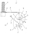
- a device 100 for actuating one is not closer here Throttle valve shown of an internal combustion engine by means of a Throttle twist grip 102 shown.
- Throttle twist grip 102 Such facilities can be found typically on motorcycles, with the throttle grip 102 is tubular, cylindrical and about its longitudinal axis is rotatably arranged at the outer end of a handlebar.
- the throttle grip 102 is in an idle position corresponding to an unactuated position restoring force held against a stop. An actuation takes place by turning the throttle grip 102 counter to the Restoring force.
- a cable pulley 104 is connected coaxially to the throttle grip 102, which circumferentially receives the end of a cable pull 106 and together with the twist grip 102 is rotatable. Starting from the idle position is the cable pull 106 when the pulley 104 rotates on the Rope pulley 104 wound up against the restoring force and thus shortened, so that the throttle valve with which the cable pull 106 is at least indirectly is connected, is pivoted in the opening direction.
- the restoring force will applied by one or more springs such as 124, which on the Throttle twist grip, on cam 108 and / or on the throttle valve Act.
- the spring 124 is schematic and exemplarily as tensile coil spring shown, but can of course also designed as a torsion spring.
- the cable pull 106 is connected to the cam plate 108 and lies against the contour 110 assigned to it.
- the cam disk 108 is rotated about its axis of rotation 122 in the direction of arrow a, the cable pull 102 unwinding and a lever becoming shorter due to the radius of the contour 110 decreasing from R 1 to R 2 in the direction of the arrow a to the axis of rotation 122 is effective, so that a progressive transmission behavior is achieved.
- Throttle valve To transfer motion to the one not shown here Throttle valve is the cam plate 108 with a lever member 114 in Connection, which in turn is rotationally fixed to the throttle valve shaft 120 is connected and preferably a pin with a roller 116 at the end made of plastic.
- the end of the lever member 114 may alternatively also formed without a roller, with the contour 112 in sliding contact his.
- the lever element 114 With a further rotation of the cam plate 108 in the direction of arrow a, the lever element 114 is carried along essentially without any further relative movement between the cam plate 108 and the lever element 114, so that from a predetermined angle of rotation at least approximate a constant ratio of 1: 1 between the cam plate 108 and the lever element 114 in the direction larger throttle opening angle is reached.
- Translation device 200 is shown with FIG. 2. It is analogous to FIG a twist grip 202 by means of a cable 206 with a cam 208 connected, which has a contour 210 assigned to it has progressive motion transmission. Compared to that in FIG. 1 illustrated embodiment, however, the distance increases Contour 212 of the cam disk 208 to the axis of rotation of the cam disk 222 when actuated in the direction of a larger throttle valve opening angle much stronger.
- the contour 212 only initially follows that The direction of arrow b is strongly curved and at the end opposite to the direction of arrow b directed so that a progressive change in the throttle valve opening movement not only up to a gear ratio of 1: 1, but in addition, a quick translation is achieved.
- the contour 212 is to ensure perfect functionality, for example with a Damage or failure of a return spring such as 224 to ensure as closed backdrop trained.
- contour 212 Due to the particularly high progression achieved with contour 212 can the - usually necessary but undesirable - progression, which is generated with the contour 210 reduces the progressive Total gear ratio between throttle 202 and Throttle valve, however, are retained. With an actuation path / angle at throttle 202 of approx. 75 °, the throttle valve can be moved from Idle stop to full load stop, correspondingly usually at an angle of approx. 85 °.
- stop screws 226, 228 are provided, the Stop screw 226 in a known manner as an idle stop for the Throttle valve / shaft is provided while the stop screw 228 serves to set the stop position of the cam disc 208. through the stop screw 228 becomes the stop position of the cam disk 208 chosen so that the contour 212 and the pin with roller 216, which in Otherwise also without a roller, with the contour 212 in sliding contact, can be designed to cooperate at least approximately without play.
- throttle valve (s) is (are) used for Regulation of the gas volume flowing into the cylinder (s), whereby an admixture of the fuel, for example, by manifold injection he follows.
- FIG. 3 shows in a diagram 300 the relationship between the Path of the cable pull 106, 206 and the opening angle of the throttle valve (s), where on the ordinate 304 the cable route and on the abscissa 306 the Throttle valve opening angle is applied.
- the curved curve 302 shows the progressive overall transmission behavior, which is decisive by the contours 110, 210 and 112, 212 and the axis offset e (FIG. 1) is determined.
- a translation takes place based on the idle position the slow movement, with a particularly good dosage is achieved in that when the throttle grip 102, 202 is actuated relatively little actuation of the throttle valve (s) takes place.
Landscapes
- Engineering & Computer Science (AREA)
- Chemical & Material Sciences (AREA)
- Combustion & Propulsion (AREA)
- Mechanical Engineering (AREA)
- General Engineering & Computer Science (AREA)
- Control Of Throttle Valves Provided In The Intake System Or In The Exhaust System (AREA)
- Harvester Elements (AREA)
- Mechanically-Actuated Valves (AREA)
Abstract
Description
- Figur 1
- eine Einrichtung zur Betätigung wenigstens einer Drosselklappe mit einer im kinematischen Übertragungsweg zwischen Gasdrehgriff und Drosselklappe angeordneten Übersetzungseinrichtung mit Kurvenscheibe und Hebeleinrichtung,
- Figur 2
- eine Einrichtung zur Betätigung wenigstens einer Drosselklappe mit einer im kinematischen Übertragungsweg zwischen Gasdrehgriff und Drosselklappe angeordnete Übersetzungseinrichtung mit Kurvenscheibe und Hebeleinrichtung und
- Figur 3
- ein Diagramm.
Claims (9)
- Einrichtung zur Betätigung wenigstens einer Drosselklappe mitdadurch gekennzeichnet, dass die Übersetzungseinrichtung (100, 200) ein mit der Drosselklappe verbundenes Hebelelement (114, 214) sowie eine mit diesem zusammenwirkende, mittels der Betätigungseinrichtung betätigbare Kurvenscheibe (108, 208) umfasst.einer Betätigungseinrichtung, wie Gasdrehgriff,wenigstens einer mit dieser kinematisch gekoppelten, über einen Betätigungswinkel verschwenkbaren Drosselklappe sowieeiner im Übertragungsweg zwischen Betätigungseinrichtung und Drosselklappe(n) angeordneten Übersetzungseinrichtung zur Erzeugung eines progressiven Übertragungsverhaltens zumindest in einem unteren Lastbereich,
- Einrichtung nach Anspruch 1, dadurch gekennzeichnet, dass die Kurvenscheibe (108, 208) eine mit dem Hebelelement (114, 214) in Wirkverbindung stehende Kontur (112, 212) aufweist, welche einen zunehmenden Abstand zu ihrer Drehachse (122, 222) aufweist, so dass bei einer Betätigung ausgehend von einer Leerlaufstellung über den unteren Lastbereich in Richtung eines mittleren und oberen Lastbereiches ein zunehmender Radius (R3) wirksam ist.
- Einrichtung nach Anspruch 1 oder 2, dadurch gekennzeichnet, dass die Drehachse (122, 222) der Kurvenscheibe (108, 208) exzentrisch mit einem Abstand (e) zur Drosselwellendrehachse (120) angeordnet ist.
- Einrichtung nach einem der vorhergehenden Ansprüche, dadurch gekennzeichnet, dass die Kurvenscheibe (108, 208) mit der Betätigungseinrichtung (102, 202) mittels eines Seilzuges (106, 206) verbunden ist und eine dem Seilzug (106, 206) zugeordnete Kontur (110, 210) aufweist, welche einen abnehmenden Abstand zu ihrer Drehachse (122, 222) aufweist, so dass bei einer Betätigung ausgehend von einer Leerlaufstellung über den unteren Lastbereich in Richtung eines mittleren und oberen Lastbereiches ein abnehmender Radius (R1, R2) wirksam ist.
- Einrichtung nach einem der vorhergehenden Ansprüche, dadurch gekennzeichnet, dass sich bei einer Betätigung ausgehend von der Leerlaufstellung, wobei eine Drehung der Kurvenscheibe (108, 208) ins Langsame übersetzt auf die Drosselklappe übertragen wird, über den unteren Lastbereich in Richtung eines mittleren und oberen Lastbereiches das Übersetzungsverhältnis vergrößert und bei einem vorbestimmten Öffnungswinkel eine Übersetzung von zumindest annähernd 1:1 erreicht ist.
- Einrichtung nach Anspruch 5, dadurch gekennzeichnet, dass sich bei einer Betätigung über den vorbestimmten Öffnungswinkel hinaus das Übersetzungsverhältnis nicht weiter erhöht.
- Einrichtung nach Anspruch 5, dadurch gekennzeichnet, dass sich bei einer Betätigung über den vorbestimmten Öffnungswinkel hinaus das Übersetzungsverhältnis weiter erhöht, so dass eine Übersetzung ins Schnelle erreicht wird.
- Einrichtung nach einem der Ansprüche 5 bis 7, gekennzeichnet durch eine Übertragungsfunktion (302) mit einem relativ flachen Verlauf im unteren Lastbereich (d), einem mittleren Bereich (e) mit einer hohen Progression sowie einem relativ steilen Verlauf im oberen Lastbereich (f).
- Einrichtung nach einem der vorhergehenden Ansprüche, gekennzeichnet durch eine Einrichtung (228) zur Einstellung des Spiels zwischen Kurvenscheibenkontur (112, 212) und Hebelelement (114, 214).
Applications Claiming Priority (2)
| Application Number | Priority Date | Filing Date | Title |
|---|---|---|---|
| DE2003123121 DE10323121A1 (de) | 2003-05-22 | 2003-05-22 | Einrichtung zur Betätigung wenigstens einer Drosselklappe |
| DE10323121 | 2003-05-22 |
Publications (3)
| Publication Number | Publication Date |
|---|---|
| EP1479891A2 true EP1479891A2 (de) | 2004-11-24 |
| EP1479891A3 EP1479891A3 (de) | 2004-12-22 |
| EP1479891B1 EP1479891B1 (de) | 2006-07-19 |
Family
ID=33039263
Family Applications (1)
| Application Number | Title | Priority Date | Filing Date |
|---|---|---|---|
| EP20040010806 Expired - Lifetime EP1479891B1 (de) | 2003-05-22 | 2004-05-04 | Einrichtung zur Betätigung wenigstens einer Drosselklappe |
Country Status (2)
| Country | Link |
|---|---|
| EP (1) | EP1479891B1 (de) |
| DE (2) | DE10323121A1 (de) |
Cited By (2)
| Publication number | Priority date | Publication date | Assignee | Title |
|---|---|---|---|---|
| EP2177737A3 (de) * | 2008-10-15 | 2011-08-24 | Steven Richard Scott | Drehgasgriff mit variabler Rate |
| JP2017160810A (ja) * | 2016-03-08 | 2017-09-14 | 豊田鉄工株式会社 | スロットル弁開閉制御装置 |
Family Cites Families (5)
| Publication number | Priority date | Publication date | Assignee | Title |
|---|---|---|---|---|
| GB1133721A (en) * | 1965-01-29 | 1968-11-13 | Smiths Industries Ltd | Improvements in or relating to variable ratio transmission devices for incorporation in throttle linkages |
| JPS57198329A (en) * | 1981-05-30 | 1982-12-04 | Nippon Denso Co Ltd | Opening and closing device of intake air throttle valve for internal combustion engine |
| DE3329791A1 (de) * | 1983-08-18 | 1985-02-28 | Vdo Adolf Schindling Ag, 6000 Frankfurt | Motorisch angetriebenes stellglied fuer die schwenkachse einer drosselklappe |
| US5239891A (en) * | 1991-10-07 | 1993-08-31 | Ford Motor Company | Cam follower variable ratio throttle linkage |
| US5165298A (en) * | 1991-10-08 | 1992-11-24 | General Motors Corporation | Throttle cable linkage |
-
2003
- 2003-05-22 DE DE2003123121 patent/DE10323121A1/de not_active Withdrawn
-
2004
- 2004-05-04 DE DE200450000975 patent/DE502004000975D1/de not_active Expired - Lifetime
- 2004-05-04 EP EP20040010806 patent/EP1479891B1/de not_active Expired - Lifetime
Cited By (3)
| Publication number | Priority date | Publication date | Assignee | Title |
|---|---|---|---|---|
| EP2177737A3 (de) * | 2008-10-15 | 2011-08-24 | Steven Richard Scott | Drehgasgriff mit variabler Rate |
| US9897014B2 (en) | 2008-10-15 | 2018-02-20 | Motion Pro, Inc. | Variable rate push/pull twist throttle |
| JP2017160810A (ja) * | 2016-03-08 | 2017-09-14 | 豊田鉄工株式会社 | スロットル弁開閉制御装置 |
Also Published As
| Publication number | Publication date |
|---|---|
| DE502004000975D1 (de) | 2006-08-31 |
| DE10323121A1 (de) | 2004-12-16 |
| EP1479891B1 (de) | 2006-07-19 |
| EP1479891A3 (de) | 2004-12-22 |
Similar Documents
| Publication | Publication Date | Title |
|---|---|---|
| DE3417814C2 (de) | ||
| DE10255299A1 (de) | Pleuel zur Verwendung an einer Hubkolbenmaschine mit veränderbar einstellbarem Verdichtungsverhältnis | |
| DE19524941B4 (de) | Lastverstellvorrichtung | |
| DE2155681A1 (de) | Vorrichtung zur Betriebssicherung des Drosselklappen-Steuermechanismus für Vergaser von Brennkraftmaschinen | |
| DE2308260C2 (de) | Fliehkraftdrehzahlregler für Einspritzbrennkraftmaschinen | |
| WO2003029632A1 (de) | Stelleinheit | |
| DE3210603C2 (de) | ||
| DE2410530C3 (de) | Vorrichtung zur Steuerung einer schwenkbar gelagerten Drosselklappe in einem Vergaser | |
| DE2334729B2 (de) | Fliehkraftdrehzahlregler für Einspritzbrennkraftmaschinen | |
| DE2931298C2 (de) | Registervergaser für Brennkraftmaschinen | |
| EP2743478B1 (de) | Arbeitsgerät | |
| DE102006048616A1 (de) | Ventilvorrichtung | |
| WO1994003709A1 (de) | Motorventilabschaltung mittels nockenrollenverlagerung | |
| EP1479891B1 (de) | Einrichtung zur Betätigung wenigstens einer Drosselklappe | |
| DE2855889C2 (de) | Leerlauf- und Enddrehzahlregler einer Kraftstoffeinspritzpumpe für Einspritzbrennkraftmaschinen, insbesondere für Fahrzeuge | |
| DE102009054687A1 (de) | Viergelenk-Koppelgetriebe sowie Abgasturbolader | |
| DE102009036914A1 (de) | Stellanordnung zum Verstellen eines Ventils | |
| DE3901264A1 (de) | Zweiflutiges drosselklappenteil | |
| DE2938200C2 (de) | ||
| EP2501921B1 (de) | Stellvorrichtung zur umwandlung einer rotatorischen bewegung in eine lineare bewegung | |
| DE10236022B4 (de) | Einlassluft-Drosselventilvorrichtung | |
| DE4036953C1 (en) | Throttle linkage in vehicle - involves link lever with slot and several coil springs | |
| DE102005062998B4 (de) | Kraftfahrzeugtürverschluss | |
| WO2004085805A1 (de) | Vorrichtung zur betätigung von ladungswechselventilen in hubkolbenmotoren | |
| DE19800456A1 (de) | Drosselventilvorrichtung eines Motors mit innerer Verbrennung |
Legal Events
| Date | Code | Title | Description |
|---|---|---|---|
| PUAI | Public reference made under article 153(3) epc to a published international application that has entered the european phase |
Free format text: ORIGINAL CODE: 0009012 |
|
| PUAL | Search report despatched |
Free format text: ORIGINAL CODE: 0009013 |
|
| AK | Designated contracting states |
Kind code of ref document: A2 Designated state(s): AT BE BG CH CY CZ DE DK EE ES FI FR GB GR HU IE IT LI LU MC NL PL PT RO SE SI SK TR |
|
| AX | Request for extension of the european patent |
Extension state: AL HR LT LV MK |
|
| AK | Designated contracting states |
Kind code of ref document: A3 Designated state(s): AT BE BG CH CY CZ DE DK EE ES FI FR GB GR HU IE IT LI LU MC NL PL PT RO SE SI SK TR |
|
| AX | Request for extension of the european patent |
Extension state: AL HR LT LV MK |
|
| 17P | Request for examination filed |
Effective date: 20050120 |
|
| AKX | Designation fees paid |
Designated state(s): DE GB IT |
|
| GRAP | Despatch of communication of intention to grant a patent |
Free format text: ORIGINAL CODE: EPIDOSNIGR1 |
|
| GRAS | Grant fee paid |
Free format text: ORIGINAL CODE: EPIDOSNIGR3 |
|
| GRAA | (expected) grant |
Free format text: ORIGINAL CODE: 0009210 |
|
| AK | Designated contracting states |
Kind code of ref document: B1 Designated state(s): DE GB IT |
|
| PG25 | Lapsed in a contracting state [announced via postgrant information from national office to epo] |
Ref country code: IT Free format text: LAPSE BECAUSE OF FAILURE TO SUBMIT A TRANSLATION OF THE DESCRIPTION OR TO PAY THE FEE WITHIN THE PRESCRIBED TIME-LIMIT;WARNING: LAPSES OF ITALIAN PATENTS WITH EFFECTIVE DATE BEFORE 2007 MAY HAVE OCCURRED AT ANY TIME BEFORE 2007. THE CORRECT EFFECTIVE DATE MAY BE DIFFERENT FROM THE ONE RECORDED. Effective date: 20060719 |
|
| REG | Reference to a national code |
Ref country code: GB Ref legal event code: FG4D Free format text: NOT ENGLISH |
|
| REF | Corresponds to: |
Ref document number: 502004000975 Country of ref document: DE Date of ref document: 20060831 Kind code of ref document: P |
|
| GBT | Gb: translation of ep patent filed (gb section 77(6)(a)/1977) |
Effective date: 20060923 |
|
| PLBE | No opposition filed within time limit |
Free format text: ORIGINAL CODE: 0009261 |
|
| STAA | Information on the status of an ep patent application or granted ep patent |
Free format text: STATUS: NO OPPOSITION FILED WITHIN TIME LIMIT |
|
| 26N | No opposition filed |
Effective date: 20070420 |
|
| PGRI | Patent reinstated in contracting state [announced from national office to epo] |
Ref country code: IT Effective date: 20080801 |
|
| PGFP | Annual fee paid to national office [announced via postgrant information from national office to epo] |
Ref country code: DE Payment date: 20150515 Year of fee payment: 12 Ref country code: GB Payment date: 20150528 Year of fee payment: 12 |
|
| PGFP | Annual fee paid to national office [announced via postgrant information from national office to epo] |
Ref country code: IT Payment date: 20150513 Year of fee payment: 12 |
|
| REG | Reference to a national code |
Ref country code: DE Ref legal event code: R119 Ref document number: 502004000975 Country of ref document: DE |
|
| GBPC | Gb: european patent ceased through non-payment of renewal fee |
Effective date: 20160504 |
|
| PG25 | Lapsed in a contracting state [announced via postgrant information from national office to epo] |
Ref country code: IT Free format text: LAPSE BECAUSE OF FAILURE TO SUBMIT A TRANSLATION OF THE DESCRIPTION OR TO PAY THE FEE WITHIN THE PRESCRIBED TIME-LIMIT Effective date: 20160504 |
|
| PG25 | Lapsed in a contracting state [announced via postgrant information from national office to epo] |
Ref country code: DE Free format text: LAPSE BECAUSE OF NON-PAYMENT OF DUE FEES Effective date: 20161201 |
|
| PG25 | Lapsed in a contracting state [announced via postgrant information from national office to epo] |
Ref country code: GB Free format text: LAPSE BECAUSE OF NON-PAYMENT OF DUE FEES Effective date: 20160504 |