EP1479880A2 - Elektrischer Ventiltrieb mit Elektro- und Permanentmagneten - Google Patents
Elektrischer Ventiltrieb mit Elektro- und Permanentmagneten Download PDFInfo
- Publication number
- EP1479880A2 EP1479880A2 EP04009654A EP04009654A EP1479880A2 EP 1479880 A2 EP1479880 A2 EP 1479880A2 EP 04009654 A EP04009654 A EP 04009654A EP 04009654 A EP04009654 A EP 04009654A EP 1479880 A2 EP1479880 A2 EP 1479880A2
- Authority
- EP
- European Patent Office
- Prior art keywords
- coil
- electromagnet
- yoke
- armature
- valve train
- Prior art date
- Legal status (The legal status is an assumption and is not a legal conclusion. Google has not performed a legal analysis and makes no representation as to the accuracy of the status listed.)
- Granted
Links
Images
Classifications
-
- H—ELECTRICITY
- H01—ELECTRIC ELEMENTS
- H01F—MAGNETS; INDUCTANCES; TRANSFORMERS; SELECTION OF MATERIALS FOR THEIR MAGNETIC PROPERTIES
- H01F7/00—Magnets
- H01F7/06—Electromagnets; Actuators including electromagnets
- H01F7/08—Electromagnets; Actuators including electromagnets with armatures
- H01F7/16—Rectilinearly-movable armatures
- H01F7/1638—Armatures not entering the winding
- H01F7/1646—Armatures or stationary parts of magnetic circuit having permanent magnet
-
- F—MECHANICAL ENGINEERING; LIGHTING; HEATING; WEAPONS; BLASTING
- F01—MACHINES OR ENGINES IN GENERAL; ENGINE PLANTS IN GENERAL; STEAM ENGINES
- F01L—CYCLICALLY OPERATING VALVES FOR MACHINES OR ENGINES
- F01L9/00—Valve-gear or valve arrangements actuated non-mechanically
- F01L9/20—Valve-gear or valve arrangements actuated non-mechanically by electric means
- F01L9/21—Valve-gear or valve arrangements actuated non-mechanically by electric means actuated by solenoids
- F01L2009/2146—Latching means
- F01L2009/2148—Latching means using permanent magnet
-
- H—ELECTRICITY
- H01—ELECTRIC ELEMENTS
- H01F—MAGNETS; INDUCTANCES; TRANSFORMERS; SELECTION OF MATERIALS FOR THEIR MAGNETIC PROPERTIES
- H01F7/00—Magnets
- H01F7/06—Electromagnets; Actuators including electromagnets
- H01F7/08—Electromagnets; Actuators including electromagnets with armatures
- H01F7/16—Rectilinearly-movable armatures
- H01F2007/1692—Electromagnets or actuators with two coils
-
- H—ELECTRICITY
- H01—ELECTRIC ELEMENTS
- H01F—MAGNETS; INDUCTANCES; TRANSFORMERS; SELECTION OF MATERIALS FOR THEIR MAGNETIC PROPERTIES
- H01F7/00—Magnets
- H01F7/06—Electromagnets; Actuators including electromagnets
- H01F7/08—Electromagnets; Actuators including electromagnets with armatures
- H01F7/121—Guiding or setting position of armatures, e.g. retaining armatures in their end position
- H01F7/122—Guiding or setting position of armatures, e.g. retaining armatures in their end position by permanent magnets
Definitions
- the present invention relates to an electric valve train for internal combustion engines according to the preamble of claim 1.
- valve train is in De 197 23 405 A1 in connection with Figure 5 described.
- the valves are replaced by one of the Crankshaft driven camshaft mechanically controlled.
- electrically controlled valves are being researched, as these have a higher Promise performance yield with lower fuel consumption.
- electrical Valve drives with stroke actuators are provided with an axially displaceable armature is biased by springs and held in a central position.
- the anchor points an anchor plate.
- electromagnet on each side of the anchor plate arranged.
- electromagnet By energizing one or the other electromagnet can A magnetic field is generated in each case, the armature in one or in the other Direction pulls.
- the armature which is biased by the springs, provides a spring-mass oscillator represents.
- the anchor During a combustion cycle, the anchor must be one during each cycle Most of the cycle time in one or the other end position at which the anchor plate on one or the other electromagnet is held. In the end positions, the valve assigned to the stroke actuator is either fully open or fully closed. To anchor in one or the other To hold the end position, the associated electromagnet must be relative large holding current are energized. Overall, therefore, is a relatively high electrical "Holding power" required.
- DE 197 23 405 A1 proposes permanent magnets on the electromagnets to arrange, the magnetic field of the magnetic field of the assigned Electromagnet is rectified.
- the armature exerted magnetic forces in the respective holding position supports the magnetic field of the associated electromagnet, so that the Keeping the armature required current is lower.
- the permanent magnets are arranged laterally on pole pieces of the electromagnets. It is not without its problems. With stroke actuators can namely considerable mechanical loads occur, in particular vibration loads. Individual components, e.g. the permanent magnets must be very firmly attached to the yoke of the associated electromagnet to be attached to detach in continuous operation prevent due to mechanical loads.
- the object of the invention is a stroke actuator for an electric valve train to create with electro and permanent magnets, in which the permanent magnets are arranged magnetically cheap, mechanically firm and space-saving.
- the invention relates to a known electric valve train for Internal combustion engines made of a movable anchor with an anchor plate and a first and a second electromagnet, which is on both sides are arranged with respect to the anchor plate.
- the electromagnets each have yoke formed from a laminated core and an electrical one arranged thereon Reel up.
- a magnetic field can be generated, which pulls the armature towards a first end position and through Energizing the coil of the other electromagnet, a magnetic field can be generated, that pulls the anchor in the opposite direction to a second end position.
- the or the Permanent magnets pull or pull the armature when it is in the close range of the associated electromagnet.
- the yoke on which the at least one permanent magnet is arranged is, seen from the anchor plate, in the area "behind” the coil Recess in which the at least one permanent magnet is arranged.
- the at least one permanent magnet is thus "embedded” in a form-fitting manner in the yoke.
- the coil of the electromagnet (s) is positively between Pole shoes of the associated yoke arranged.
- the at least one permanent magnet is positively arranged in a recess of the respective yoke.
- the coil and the at least one permanent magnet are preferably in poured the yoke. That is, between the yoke, coil and permanent magnet a hardening binder, e.g. Cast in epoxy resin. After curing of the binder you get a very compact, robust unit.
- the yokes of the electromagnets are preferably also arranged in a housing. For reasons of strength, it is advantageous if the yokes are also in the Housing are cast.
- the "housing" is in a real engine through the Cylinder head formed. To the mechanical connection of the yoke with the surrounding Housing can further improve on the outside of the yokes or more undercut elements can be arranged when pouring the yokes are filled in the housing of housing material. This is a positive Connection of the yokes to the housing reached.
- the at least one permanent magnet is preferably in the region between the Coil and the at least one undercut element arranged. That from The undercut element protruding from the outer circumference of the yoke constitutes a "Material accumulation" represents the magnetic flux in the area of at least favored a permanent magnet.
- one or more, e.g. two permanent magnets per Yoke may be provided.
- the two permanent magnets can be in their north-south direction seen spaced apart. It can also be provided that the permanent magnets are in a direction transverse to their north-south direction are staggered.
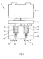
- Figure 1 shows a stroke actuator 1 according to the invention in a schematic representation.
- the stroke actuator 1 has a first electromagnet 2 and a second Electromagnet 3 on. Furthermore, a spring biased 4, 5 in a central position Anchor is provided, of which only one anchor plate 6 is shown here.
- the Armature plate 6 is arranged between the two electromagnets 2, 3.
- the anchor also has a shaft, not shown here, and is between an upper one and lower end position axially displaceable between the two electromagnets arranged.
- the electromagnets each have a sheet metal stack Yoke 7 with pole shoes 8-10.
- the pole shoes 8-10 have recesses 11, 12 formed in which a coil 13 of the electromagnet is arranged is.
- the yoke 7 points in the area "behind” the coil 13 recesses 14, 15, in each of which a permanent magnet 16, 17th is arranged.
- the yoke has two permanent magnets 16, 17 on its outside dovetail-like undercut elements 18, 19.
- the Undercut elements 18, 19 serve primarily to ensure that the yoke 7, which is in a Yoke 7 surrounding housing - e.g. a cylinder head - is cast in, positive and therefore mechanically robust with the housing (not shown) connected is.
- the undercut elements 18, 19 thus provide a form fit reached between the yoke 7 and the surrounding housing (not shown).
- the electromagnet 2 shown here only schematically can be quite analogous to that Electromagnet 3 can be constructed.
- the arrangement of the permanent magnets 16, 17 in the area of Undercut elements is the mechanical strength of the laminated yoke 7 guaranteed.
- the risk that the laminated yoke 7 is divided into several sections divides does not exist. Overall results from the described Arrangement high stability with little production engineering effort.
- the armature By energizing the coil 13, the armature can move towards the electromagnet 3 be pulled there. If the armature plate 6 is in the vicinity of the electromagnet 3 is located, the anchor plate is in addition to that generated by the coil 13 Magnetic field detected by the magnetic field of the permanent magnets 16, 17. To the Holding the anchor plate 6 in the end position in which the anchor plate 6 rests on the yoke 7, is therefore a lower holding current due to the permanent magnets 14, 15 required than with purely electromagnetic actuation of the armature, i.e. if no Permanent magnets would be present.
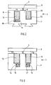
- FIG. 2 shows a variant of the electromagnet 3 shown in Figure 1 Stroke actuator.
- the permanent magnet 16 here is somewhat wider than that in FIG Figure 1 provided electromagnet 16.
- the electromagnet 16 of Figure 2 has in essentially the same width as the coil 13. The recesses go accordingly 11 and 14 one above the other or through a single groove in the yoke 7 educated.
- FIG. 3 shows a further variant of the electromagnet 3. Similar to that in FIG. 1 two permanent magnets 16, 17 are provided here. However, these are not in the middle arranged below the coil 13, but offset towards the center of the yoke 7. As can be seen from Figure 3, the permanent magnets 16, 17 have something smaller width than the coil 13. Accordingly, the recesses have 14, 15 a slightly smaller width than the recesses 11, 12.
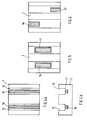
- Figures 4a, 4b, 5, 6 show top views of different variants of the invention.
- the permanent magnets 14, 15 arranged centrally below the recesses 11, 12.
- the permanent magnets 16, 17 extend over the entire Length of the yoke 7.
- the permanent magnets 16, 17 are shorter than in the embodiment of Figures 4a, 4b.
- the permanent magnets 16, 17 are arranged centrally on the yoke 7 with respect to their longitudinal direction.
- the permanent magnets 16, 17 are in the embodiment 6 is arranged offset on the yoke 7 in its longitudinal direction.
Landscapes
- Physics & Mathematics (AREA)
- Electromagnetism (AREA)
- Engineering & Computer Science (AREA)
- Power Engineering (AREA)
- Valve Device For Special Equipments (AREA)
Abstract
Description
- Figur 1
- das Grundprinzip eines Hubaktuators gemäß der Erfindung;
- Figuren 2, 3
- verschiedene Varianten eines Elektromagneten der Hubaktuoranordnung im Querschnitt;
- Figuren 4a, 4b, 5, 6
- verschiedene Anordnungsmöglichkeiten der Permanentmagneten im Joch des zugeordneten Elektromagneten.
Claims (11)
- Elektrischer Ventiltrieb für Verbrennungsmotoren mit einem verschieblich angeordneten Anker, der eine Ankerplatte (6) aufweist, einem ersten Elektromagneten (2), der auf der einen Seite der Ankerplatte (6) angeordnet ist und einem zweiten Elektromagneten (3), der auf der anderen Seite der Ankerplatte (6) angeordnet ist, wobei
die Elektromagneten (2, 3) jeweils ein Joch (7) und eine daran angeordnete Spule (13) aufweisen und durch Bestromen der Spule (13) des einen Elektromagneten (2) ein Magnetfeld erzeugbar ist, das den Anker in Richtung einer ersten Endstellung zieht und durch Bestromen des anderen Elektromagneten (3) ein Magnetfeld erzeugbar ist, das den Anker in entgegengesetzte Richtung zu einer zweiten Endstellung zieht, und wobei
an mindestens einem der Joche (7) mindestens ein Permanentmagnet (16, 17) angeordnet ist, welcher, insbesondere wenn sich die Ankerplatte (6) in einem Nahbereich des zugeordneten Elektromagneten (3) befindet, den Anker anzieht,
dadurch gekennzeichnet, dass
der mindestens eine Permanentmagnet (16, 17) auf einer der Ankerplatte (6) abgewandten Seite der Spule (13) des zugeordneten Elektromagneten (3) angeordnet ist. - Elektrischer Ventiltrieb nach Anspruch 1, wobei das Joch (7), an dem der mindestens eine Permanentmagnet (16, 17) angeordnet ist, eine Ausnehmung (11, 12) aufweist, in der die zugeordnete Spule (13) angeordnet ist und dass von der Ankerplatte (6) aus gesehen in einem Bereich hinter der Spule (13) eine Ausnehmung (14, 15) im Joch (7) vorgesehen ist, in welcher der mindestens eine Permanentmagnet (16, 17) angeordnet ist.
- Elektrischer Ventiltrieb nach Anspruch 1 oder 2, wobei der mindestens eine Permanentmagnet (16, 17) von der Ankerplatte (6) aus gesehen in einem Bereich hinter den Windungen der Spule (13) angeordnet ist.
- Elektrischer Ventiltrieb nach einem der Ansprüche 2 oder 3, wobei die Spule (13) und der mindestens eine Permanentmagnet (16, 17) an dem zugeordneten Joch (7) durch ein zwischen Joch (7), Spule (13) und Permanentmagnet (16, 17) eingegossenes und anschließend ausgehärtetes Bindemittel fixiert sind.
- Elektrischer Ventiltrieb nach einem der Ansprüche 1 bis 4, wobei das Joch (7) in einem Gehäuse angeordnet ist.
- Elektrischer Ventiltrieb nach einem der Ansprüche 1 bis 5, wobei das Joch (7) in ein Gehäuse eingegossen ist.
- Elektrischer Ventiltrieb nach Anspruch 6, wobei das Joch (7) an seiner Außenseite mindestens ein von der Außenseite abstehendes Hinterschnittelement (18, 19) aufweist, wobei ein durch das Hinterschnittelement (18, 19) gebildeter Hinterschnitt vom Material des Gehäuses ausgefüllt ist und dadurch formschlüssig mit dem Gehäuse verbunden ist.
- Elektrischer Ventiltrieb nach Anspruch 7, wobei der mindestens eine Permanentmagnet (16, 17) im Bereich zwischen der zugeordneten Spule (13) und dem mindestens einen Hinterschnittelement (18, 19) angeordnet ist.
- Elektrischer Ventiltrieb nach einem der Ansprüche 1 bis 8, wobei mindestens an einem der beiden Joche (7) der Elektromagneten (2, 3) zwei Permanentmagneten (16, 17) angeordnet sind.
- Elektrischer Ventiltrieb nach Anspruch 9, wobei die beiden Permanentmagneten (16, 17) in ihrer Nord-Süd-Richtung gesehen voneinander beabstandet angeordnet sind.
- Elektrischer Ventiltrieb nach Anspruch 9 oder 10, wobei die beiden Permanentmagneten (16, 17) in einer Richtung, die quer zu ihrer Nord-Süd-Richtung ist, versetzt zueinander angeordnet sind.
Applications Claiming Priority (2)
| Application Number | Priority Date | Filing Date | Title |
|---|---|---|---|
| DE10322881A DE10322881A1 (de) | 2003-05-21 | 2003-05-21 | Elektrischer Ventiltrieb mit Elektro- und Permanentmagneten |
| DE10322881 | 2003-05-21 |
Publications (3)
| Publication Number | Publication Date |
|---|---|
| EP1479880A2 true EP1479880A2 (de) | 2004-11-24 |
| EP1479880A3 EP1479880A3 (de) | 2006-05-24 |
| EP1479880B1 EP1479880B1 (de) | 2008-08-20 |
Family
ID=33039239
Family Applications (1)
| Application Number | Title | Priority Date | Filing Date |
|---|---|---|---|
| EP04009654A Expired - Lifetime EP1479880B1 (de) | 2003-05-21 | 2004-04-22 | Elektrischer Ventiltrieb mit Elektro- und Permanentmagneten |
Country Status (2)
| Country | Link |
|---|---|
| EP (1) | EP1479880B1 (de) |
| DE (2) | DE10322881A1 (de) |
Cited By (1)
| Publication number | Priority date | Publication date | Assignee | Title |
|---|---|---|---|---|
| CN109817408A (zh) * | 2017-11-21 | 2019-05-28 | 三花亚威科电器设备(芜湖)有限公司 | 电磁铁和具有该电磁铁的电磁阀 |
Family Cites Families (8)
| Publication number | Priority date | Publication date | Assignee | Title |
|---|---|---|---|---|
| US4829947A (en) * | 1987-08-12 | 1989-05-16 | General Motors Corporation | Variable lift operation of bistable electromechanical poppet valve actuator |
| JP3186462B2 (ja) * | 1994-09-22 | 2001-07-11 | トヨタ自動車株式会社 | 内燃機関の電磁式弁駆動装置 |
| JPH1047028A (ja) * | 1996-07-31 | 1998-02-17 | Suzuki Motor Corp | 電磁弁型エンジンの制御装置 |
| DE19723405A1 (de) * | 1997-06-04 | 1998-12-10 | Fev Motorentech Gmbh & Co Kg | Verfahren zur Steuerung eines elektromagnetischen Ventilbetriebes für ein Gaswechselventil |
| DE19712293A1 (de) * | 1997-03-24 | 1998-10-01 | Binder Magnete | Elektromagnetisch arbeitende Stelleinrichtung |
| US6274954B1 (en) * | 1997-10-10 | 2001-08-14 | Daimlerchrysler Ag | Electromagnetic actuator for actuating a gas-exchanging valve |
| JP3547115B2 (ja) * | 1998-06-11 | 2004-07-28 | トヨタ自動車株式会社 | 電磁駆動バルブ |
| JP2002364391A (ja) * | 2001-06-08 | 2002-12-18 | Toyota Motor Corp | 電磁駆動弁の中立位置変化検出装置 |
-
2003
- 2003-05-21 DE DE10322881A patent/DE10322881A1/de not_active Withdrawn
-
2004
- 2004-04-22 EP EP04009654A patent/EP1479880B1/de not_active Expired - Lifetime
- 2004-04-22 DE DE502004007871T patent/DE502004007871D1/de not_active Expired - Lifetime
Cited By (2)
| Publication number | Priority date | Publication date | Assignee | Title |
|---|---|---|---|---|
| CN109817408A (zh) * | 2017-11-21 | 2019-05-28 | 三花亚威科电器设备(芜湖)有限公司 | 电磁铁和具有该电磁铁的电磁阀 |
| CN109817408B (zh) * | 2017-11-21 | 2022-05-10 | 三花亚威科电器设备(芜湖)有限公司 | 电磁铁和具有该电磁铁的电磁阀 |
Also Published As
| Publication number | Publication date |
|---|---|
| EP1479880A3 (de) | 2006-05-24 |
| EP1479880B1 (de) | 2008-08-20 |
| DE10322881A1 (de) | 2004-12-16 |
| DE502004007871D1 (de) | 2008-10-02 |
Similar Documents
| Publication | Publication Date | Title |
|---|---|---|
| EP2158596B1 (de) | Elektromagnetische stellvorrichtung | |
| EP2191107B1 (de) | Elektromagnetische stellvorrichtung | |
| DE3024109A1 (de) | Elektromagnetisch arbeitende stelleinrichtung | |
| EP0796981A1 (de) | Elektromagnetische Betätigungsvorrichtung für Brennkraftmaschinen-Hubventile | |
| EP3191695B1 (de) | Elektromagnetische stellvorrichtung | |
| DE102009015486A1 (de) | Elektromagnetischer Aktuator | |
| DE19751609B4 (de) | Schmalbauender elektromagnetischer Aktuator | |
| EP0748416B1 (de) | Elektromagnetische Stellvorrichtung eines Gaswechselventils an einer Kolbenbrennkraftmaschine | |
| EP2724354B1 (de) | Elektromagnetische stellvorrichtung sowie nockenwellenverstellvorrichtung | |
| DE9412763U1 (de) | Motorbremsvorrichtung für einen Nutzfahrzeugmotor | |
| EP0935054A2 (de) | Elektromagnetischer Aktuator | |
| DE19839580A1 (de) | Elektromagnet für eine Treibstoffeinspritzvorrichtung | |
| EP1479880B1 (de) | Elektrischer Ventiltrieb mit Elektro- und Permanentmagneten | |
| DE19719299C1 (de) | Betätigungseinrichtung für Gaswechselventile einer Brennkraftmaschine mit elektromagnetischen Aktuatoren | |
| DE102011012020B4 (de) | Nockenwelle mit Nockenwellenversteller | |
| DE3018972C2 (de) | Magnetventil | |
| DE102013108029A1 (de) | Elektromagnetische Stellvorrichtung | |
| EP1004755B1 (de) | Herstellverfahren für einen stösselgeführten Anker eines Aktuators für Hubventile einer Brennkraftmaschine | |
| DE10051076C2 (de) | Verfahren zur Herstellung eines elektromagnetischen Aktuators | |
| DE10317644A1 (de) | Elektromagnetischer Aktuator mit unsymmetrischer Magnetkreisauslegung zur Betätigung eines Gaswechselventils | |
| EP2649281B1 (de) | Nockenwellenbaugruppe sowie verfahren zum herstellen einer nockenwellenbaugruppe | |
| DE202004011676U1 (de) | Elektromagnetische Linear-Stelleinrichtung | |
| EP3361085A1 (de) | Elektromagnetisches schaltventil und kraftstoffhochdruckpumpe | |
| DE10119291A1 (de) | Aktor zur elektromagnetischen Ventilsteuerung | |
| WO2001006159A1 (de) | Elektromagnetischer antrieb |
Legal Events
| Date | Code | Title | Description |
|---|---|---|---|
| PUAI | Public reference made under article 153(3) epc to a published international application that has entered the european phase |
Free format text: ORIGINAL CODE: 0009012 |
|
| AK | Designated contracting states |
Kind code of ref document: A2 Designated state(s): AT BE BG CH CY CZ DE DK EE ES FI FR GB GR HU IE IT LI LU MC NL PL PT RO SE SI SK TR |
|
| AX | Request for extension of the european patent |
Extension state: AL HR LT LV MK |
|
| PUAL | Search report despatched |
Free format text: ORIGINAL CODE: 0009013 |
|
| AK | Designated contracting states |
Kind code of ref document: A3 Designated state(s): AT BE BG CH CY CZ DE DK EE ES FI FR GB GR HU IE IT LI LU MC NL PL PT RO SE SI SK TR |
|
| AX | Request for extension of the european patent |
Extension state: AL HR LT LV MK |
|
| 17P | Request for examination filed |
Effective date: 20060608 |
|
| AKX | Designation fees paid |
Designated state(s): DE FR GB IT |
|
| 17Q | First examination report despatched |
Effective date: 20070322 |
|
| GRAP | Despatch of communication of intention to grant a patent |
Free format text: ORIGINAL CODE: EPIDOSNIGR1 |
|
| RIC1 | Information provided on ipc code assigned before grant |
Ipc: H01F 7/128 20060101ALI20080306BHEP Ipc: H01F 7/16 20060101ALI20080306BHEP Ipc: F01L 9/04 20060101AFI20080306BHEP |
|
| GRAS | Grant fee paid |
Free format text: ORIGINAL CODE: EPIDOSNIGR3 |
|
| GRAA | (expected) grant |
Free format text: ORIGINAL CODE: 0009210 |
|
| AK | Designated contracting states |
Kind code of ref document: B1 Designated state(s): DE FR GB IT |
|
| REG | Reference to a national code |
Ref country code: GB Ref legal event code: FG4D Free format text: NOT ENGLISH |
|
| REF | Corresponds to: |
Ref document number: 502004007871 Country of ref document: DE Date of ref document: 20081002 Kind code of ref document: P |
|
| PLBE | No opposition filed within time limit |
Free format text: ORIGINAL CODE: 0009261 |
|
| STAA | Information on the status of an ep patent application or granted ep patent |
Free format text: STATUS: NO OPPOSITION FILED WITHIN TIME LIMIT |
|
| 26N | No opposition filed |
Effective date: 20090525 |
|
| REG | Reference to a national code |
Ref country code: FR Ref legal event code: PLFP Year of fee payment: 12 |
|
| PGFP | Annual fee paid to national office [announced via postgrant information from national office to epo] |
Ref country code: DE Payment date: 20150411 Year of fee payment: 12 Ref country code: GB Payment date: 20150430 Year of fee payment: 12 |
|
| PGFP | Annual fee paid to national office [announced via postgrant information from national office to epo] |
Ref country code: FR Payment date: 20150430 Year of fee payment: 12 Ref country code: IT Payment date: 20150428 Year of fee payment: 12 |
|
| REG | Reference to a national code |
Ref country code: DE Ref legal event code: R119 Ref document number: 502004007871 Country of ref document: DE |
|
| GBPC | Gb: european patent ceased through non-payment of renewal fee |
Effective date: 20160422 |
|
| REG | Reference to a national code |
Ref country code: FR Ref legal event code: ST Effective date: 20161230 |
|
| PG25 | Lapsed in a contracting state [announced via postgrant information from national office to epo] |
Ref country code: DE Free format text: LAPSE BECAUSE OF NON-PAYMENT OF DUE FEES Effective date: 20161101 Ref country code: FR Free format text: LAPSE BECAUSE OF NON-PAYMENT OF DUE FEES Effective date: 20160502 Ref country code: GB Free format text: LAPSE BECAUSE OF NON-PAYMENT OF DUE FEES Effective date: 20160422 |
|
| PG25 | Lapsed in a contracting state [announced via postgrant information from national office to epo] |
Ref country code: IT Free format text: LAPSE BECAUSE OF NON-PAYMENT OF DUE FEES Effective date: 20160422 |