EP1479791A2 - Cutting tool - Google Patents
Cutting tool Download PDFInfo
- Publication number
- EP1479791A2 EP1479791A2 EP04004292A EP04004292A EP1479791A2 EP 1479791 A2 EP1479791 A2 EP 1479791A2 EP 04004292 A EP04004292 A EP 04004292A EP 04004292 A EP04004292 A EP 04004292A EP 1479791 A2 EP1479791 A2 EP 1479791A2
- Authority
- EP
- European Patent Office
- Prior art keywords
- layer
- cutting
- compound
- hard coating
- aluminum oxide
- Prior art date
- Legal status (The legal status is an assumption and is not a legal conclusion. Google has not performed a legal analysis and makes no representation as to the accuracy of the status listed.)
- Granted
Links
Images
Classifications
-
- C—CHEMISTRY; METALLURGY
- C23—COATING METALLIC MATERIAL; COATING MATERIAL WITH METALLIC MATERIAL; CHEMICAL SURFACE TREATMENT; DIFFUSION TREATMENT OF METALLIC MATERIAL; COATING BY VACUUM EVAPORATION, BY SPUTTERING, BY ION IMPLANTATION OR BY CHEMICAL VAPOUR DEPOSITION, IN GENERAL; INHIBITING CORROSION OF METALLIC MATERIAL OR INCRUSTATION IN GENERAL
- C23C—COATING METALLIC MATERIAL; COATING MATERIAL WITH METALLIC MATERIAL; SURFACE TREATMENT OF METALLIC MATERIAL BY DIFFUSION INTO THE SURFACE, BY CHEMICAL CONVERSION OR SUBSTITUTION; COATING BY VACUUM EVAPORATION, BY SPUTTERING, BY ION IMPLANTATION OR BY CHEMICAL VAPOUR DEPOSITION, IN GENERAL
- C23C16/00—Chemical coating by decomposition of gaseous compounds, without leaving reaction products of surface material in the coating, i.e. chemical vapour deposition [CVD] processes
- C23C16/02—Pretreatment of the material to be coated
- C23C16/0272—Deposition of sub-layers, e.g. to promote the adhesion of the main coating
-
- F—MECHANICAL ENGINEERING; LIGHTING; HEATING; WEAPONS; BLASTING
- F16—ENGINEERING ELEMENTS AND UNITS; GENERAL MEASURES FOR PRODUCING AND MAINTAINING EFFECTIVE FUNCTIONING OF MACHINES OR INSTALLATIONS; THERMAL INSULATION IN GENERAL
- F16B—DEVICES FOR FASTENING OR SECURING CONSTRUCTIONAL ELEMENTS OR MACHINE PARTS TOGETHER, e.g. NAILS, BOLTS, CIRCLIPS, CLAMPS, CLIPS OR WEDGES; JOINTS OR JOINTING
- F16B2/00—Friction-grip releasable fastenings
- F16B2/02—Clamps, i.e. with gripping action effected by positive means other than the inherent resistance to deformation of the material of the fastening
- F16B2/06—Clamps, i.e. with gripping action effected by positive means other than the inherent resistance to deformation of the material of the fastening external, i.e. with contracting action
- F16B2/065—Clamps, i.e. with gripping action effected by positive means other than the inherent resistance to deformation of the material of the fastening external, i.e. with contracting action using screw-thread elements
-
- C—CHEMISTRY; METALLURGY
- C23—COATING METALLIC MATERIAL; COATING MATERIAL WITH METALLIC MATERIAL; CHEMICAL SURFACE TREATMENT; DIFFUSION TREATMENT OF METALLIC MATERIAL; COATING BY VACUUM EVAPORATION, BY SPUTTERING, BY ION IMPLANTATION OR BY CHEMICAL VAPOUR DEPOSITION, IN GENERAL; INHIBITING CORROSION OF METALLIC MATERIAL OR INCRUSTATION IN GENERAL
- C23C—COATING METALLIC MATERIAL; COATING MATERIAL WITH METALLIC MATERIAL; SURFACE TREATMENT OF METALLIC MATERIAL BY DIFFUSION INTO THE SURFACE, BY CHEMICAL CONVERSION OR SUBSTITUTION; COATING BY VACUUM EVAPORATION, BY SPUTTERING, BY ION IMPLANTATION OR BY CHEMICAL VAPOUR DEPOSITION, IN GENERAL
- C23C16/00—Chemical coating by decomposition of gaseous compounds, without leaving reaction products of surface material in the coating, i.e. chemical vapour deposition [CVD] processes
- C23C16/22—Chemical coating by decomposition of gaseous compounds, without leaving reaction products of surface material in the coating, i.e. chemical vapour deposition [CVD] processes characterised by the deposition of inorganic material, other than metallic material
- C23C16/30—Deposition of compounds, mixtures or solid solutions, e.g. borides, carbides, nitrides
-
- C—CHEMISTRY; METALLURGY
- C23—COATING METALLIC MATERIAL; COATING MATERIAL WITH METALLIC MATERIAL; CHEMICAL SURFACE TREATMENT; DIFFUSION TREATMENT OF METALLIC MATERIAL; COATING BY VACUUM EVAPORATION, BY SPUTTERING, BY ION IMPLANTATION OR BY CHEMICAL VAPOUR DEPOSITION, IN GENERAL; INHIBITING CORROSION OF METALLIC MATERIAL OR INCRUSTATION IN GENERAL
- C23C—COATING METALLIC MATERIAL; COATING MATERIAL WITH METALLIC MATERIAL; SURFACE TREATMENT OF METALLIC MATERIAL BY DIFFUSION INTO THE SURFACE, BY CHEMICAL CONVERSION OR SUBSTITUTION; COATING BY VACUUM EVAPORATION, BY SPUTTERING, BY ION IMPLANTATION OR BY CHEMICAL VAPOUR DEPOSITION, IN GENERAL
- C23C16/00—Chemical coating by decomposition of gaseous compounds, without leaving reaction products of surface material in the coating, i.e. chemical vapour deposition [CVD] processes
- C23C16/22—Chemical coating by decomposition of gaseous compounds, without leaving reaction products of surface material in the coating, i.e. chemical vapour deposition [CVD] processes characterised by the deposition of inorganic material, other than metallic material
- C23C16/30—Deposition of compounds, mixtures or solid solutions, e.g. borides, carbides, nitrides
- C23C16/34—Nitrides
-
- C—CHEMISTRY; METALLURGY
- C23—COATING METALLIC MATERIAL; COATING MATERIAL WITH METALLIC MATERIAL; CHEMICAL SURFACE TREATMENT; DIFFUSION TREATMENT OF METALLIC MATERIAL; COATING BY VACUUM EVAPORATION, BY SPUTTERING, BY ION IMPLANTATION OR BY CHEMICAL VAPOUR DEPOSITION, IN GENERAL; INHIBITING CORROSION OF METALLIC MATERIAL OR INCRUSTATION IN GENERAL
- C23C—COATING METALLIC MATERIAL; COATING MATERIAL WITH METALLIC MATERIAL; SURFACE TREATMENT OF METALLIC MATERIAL BY DIFFUSION INTO THE SURFACE, BY CHEMICAL CONVERSION OR SUBSTITUTION; COATING BY VACUUM EVAPORATION, BY SPUTTERING, BY ION IMPLANTATION OR BY CHEMICAL VAPOUR DEPOSITION, IN GENERAL
- C23C16/00—Chemical coating by decomposition of gaseous compounds, without leaving reaction products of surface material in the coating, i.e. chemical vapour deposition [CVD] processes
- C23C16/22—Chemical coating by decomposition of gaseous compounds, without leaving reaction products of surface material in the coating, i.e. chemical vapour deposition [CVD] processes characterised by the deposition of inorganic material, other than metallic material
- C23C16/30—Deposition of compounds, mixtures or solid solutions, e.g. borides, carbides, nitrides
- C23C16/36—Carbonitrides
-
- C—CHEMISTRY; METALLURGY
- C23—COATING METALLIC MATERIAL; COATING MATERIAL WITH METALLIC MATERIAL; CHEMICAL SURFACE TREATMENT; DIFFUSION TREATMENT OF METALLIC MATERIAL; COATING BY VACUUM EVAPORATION, BY SPUTTERING, BY ION IMPLANTATION OR BY CHEMICAL VAPOUR DEPOSITION, IN GENERAL; INHIBITING CORROSION OF METALLIC MATERIAL OR INCRUSTATION IN GENERAL
- C23C—COATING METALLIC MATERIAL; COATING MATERIAL WITH METALLIC MATERIAL; SURFACE TREATMENT OF METALLIC MATERIAL BY DIFFUSION INTO THE SURFACE, BY CHEMICAL CONVERSION OR SUBSTITUTION; COATING BY VACUUM EVAPORATION, BY SPUTTERING, BY ION IMPLANTATION OR BY CHEMICAL VAPOUR DEPOSITION, IN GENERAL
- C23C16/00—Chemical coating by decomposition of gaseous compounds, without leaving reaction products of surface material in the coating, i.e. chemical vapour deposition [CVD] processes
- C23C16/22—Chemical coating by decomposition of gaseous compounds, without leaving reaction products of surface material in the coating, i.e. chemical vapour deposition [CVD] processes characterised by the deposition of inorganic material, other than metallic material
- C23C16/30—Deposition of compounds, mixtures or solid solutions, e.g. borides, carbides, nitrides
- C23C16/40—Oxides
- C23C16/403—Oxides of aluminium, magnesium or beryllium
-
- C—CHEMISTRY; METALLURGY
- C23—COATING METALLIC MATERIAL; COATING MATERIAL WITH METALLIC MATERIAL; CHEMICAL SURFACE TREATMENT; DIFFUSION TREATMENT OF METALLIC MATERIAL; COATING BY VACUUM EVAPORATION, BY SPUTTERING, BY ION IMPLANTATION OR BY CHEMICAL VAPOUR DEPOSITION, IN GENERAL; INHIBITING CORROSION OF METALLIC MATERIAL OR INCRUSTATION IN GENERAL
- C23C—COATING METALLIC MATERIAL; COATING MATERIAL WITH METALLIC MATERIAL; SURFACE TREATMENT OF METALLIC MATERIAL BY DIFFUSION INTO THE SURFACE, BY CHEMICAL CONVERSION OR SUBSTITUTION; COATING BY VACUUM EVAPORATION, BY SPUTTERING, BY ION IMPLANTATION OR BY CHEMICAL VAPOUR DEPOSITION, IN GENERAL
- C23C28/00—Coating for obtaining at least two superposed coatings either by methods not provided for in a single one of groups C23C2/00 - C23C26/00 or by combinations of methods provided for in subclasses C23C and C25C or C25D
- C23C28/04—Coating for obtaining at least two superposed coatings either by methods not provided for in a single one of groups C23C2/00 - C23C26/00 or by combinations of methods provided for in subclasses C23C and C25C or C25D only coatings of inorganic non-metallic material
- C23C28/042—Coating for obtaining at least two superposed coatings either by methods not provided for in a single one of groups C23C2/00 - C23C26/00 or by combinations of methods provided for in subclasses C23C and C25C or C25D only coatings of inorganic non-metallic material including a refractory ceramic layer, e.g. refractory metal oxides, ZrO2, rare earth oxides
-
- C—CHEMISTRY; METALLURGY
- C23—COATING METALLIC MATERIAL; COATING MATERIAL WITH METALLIC MATERIAL; CHEMICAL SURFACE TREATMENT; DIFFUSION TREATMENT OF METALLIC MATERIAL; COATING BY VACUUM EVAPORATION, BY SPUTTERING, BY ION IMPLANTATION OR BY CHEMICAL VAPOUR DEPOSITION, IN GENERAL; INHIBITING CORROSION OF METALLIC MATERIAL OR INCRUSTATION IN GENERAL
- C23C—COATING METALLIC MATERIAL; COATING MATERIAL WITH METALLIC MATERIAL; SURFACE TREATMENT OF METALLIC MATERIAL BY DIFFUSION INTO THE SURFACE, BY CHEMICAL CONVERSION OR SUBSTITUTION; COATING BY VACUUM EVAPORATION, BY SPUTTERING, BY ION IMPLANTATION OR BY CHEMICAL VAPOUR DEPOSITION, IN GENERAL
- C23C28/00—Coating for obtaining at least two superposed coatings either by methods not provided for in a single one of groups C23C2/00 - C23C26/00 or by combinations of methods provided for in subclasses C23C and C25C or C25D
- C23C28/04—Coating for obtaining at least two superposed coatings either by methods not provided for in a single one of groups C23C2/00 - C23C26/00 or by combinations of methods provided for in subclasses C23C and C25C or C25D only coatings of inorganic non-metallic material
- C23C28/044—Coating for obtaining at least two superposed coatings either by methods not provided for in a single one of groups C23C2/00 - C23C26/00 or by combinations of methods provided for in subclasses C23C and C25C or C25D only coatings of inorganic non-metallic material coatings specially adapted for cutting tools or wear applications
-
- C—CHEMISTRY; METALLURGY
- C23—COATING METALLIC MATERIAL; COATING MATERIAL WITH METALLIC MATERIAL; CHEMICAL SURFACE TREATMENT; DIFFUSION TREATMENT OF METALLIC MATERIAL; COATING BY VACUUM EVAPORATION, BY SPUTTERING, BY ION IMPLANTATION OR BY CHEMICAL VAPOUR DEPOSITION, IN GENERAL; INHIBITING CORROSION OF METALLIC MATERIAL OR INCRUSTATION IN GENERAL
- C23C—COATING METALLIC MATERIAL; COATING MATERIAL WITH METALLIC MATERIAL; SURFACE TREATMENT OF METALLIC MATERIAL BY DIFFUSION INTO THE SURFACE, BY CHEMICAL CONVERSION OR SUBSTITUTION; COATING BY VACUUM EVAPORATION, BY SPUTTERING, BY ION IMPLANTATION OR BY CHEMICAL VAPOUR DEPOSITION, IN GENERAL
- C23C30/00—Coating with metallic material characterised only by the composition of the metallic material, i.e. not characterised by the coating process
-
- C—CHEMISTRY; METALLURGY
- C23—COATING METALLIC MATERIAL; COATING MATERIAL WITH METALLIC MATERIAL; CHEMICAL SURFACE TREATMENT; DIFFUSION TREATMENT OF METALLIC MATERIAL; COATING BY VACUUM EVAPORATION, BY SPUTTERING, BY ION IMPLANTATION OR BY CHEMICAL VAPOUR DEPOSITION, IN GENERAL; INHIBITING CORROSION OF METALLIC MATERIAL OR INCRUSTATION IN GENERAL
- C23C—COATING METALLIC MATERIAL; COATING MATERIAL WITH METALLIC MATERIAL; SURFACE TREATMENT OF METALLIC MATERIAL BY DIFFUSION INTO THE SURFACE, BY CHEMICAL CONVERSION OR SUBSTITUTION; COATING BY VACUUM EVAPORATION, BY SPUTTERING, BY ION IMPLANTATION OR BY CHEMICAL VAPOUR DEPOSITION, IN GENERAL
- C23C30/00—Coating with metallic material characterised only by the composition of the metallic material, i.e. not characterised by the coating process
- C23C30/005—Coating with metallic material characterised only by the composition of the metallic material, i.e. not characterised by the coating process on hard metal substrates
-
- F—MECHANICAL ENGINEERING; LIGHTING; HEATING; WEAPONS; BLASTING
- F16—ENGINEERING ELEMENTS AND UNITS; GENERAL MEASURES FOR PRODUCING AND MAINTAINING EFFECTIVE FUNCTIONING OF MACHINES OR INSTALLATIONS; THERMAL INSULATION IN GENERAL
- F16B—DEVICES FOR FASTENING OR SECURING CONSTRUCTIONAL ELEMENTS OR MACHINE PARTS TOGETHER, e.g. NAILS, BOLTS, CIRCLIPS, CLAMPS, CLIPS OR WEDGES; JOINTS OR JOINTING
- F16B5/00—Joining sheets or plates, e.g. panels, to one another or to strips or bars parallel to them
- F16B5/06—Joining sheets or plates, e.g. panels, to one another or to strips or bars parallel to them by means of clamps or clips
- F16B5/0685—Joining sheets or plates to strips or bars
-
- F—MECHANICAL ENGINEERING; LIGHTING; HEATING; WEAPONS; BLASTING
- F16—ENGINEERING ELEMENTS AND UNITS; GENERAL MEASURES FOR PRODUCING AND MAINTAINING EFFECTIVE FUNCTIONING OF MACHINES OR INSTALLATIONS; THERMAL INSULATION IN GENERAL
- F16L—PIPES; JOINTS OR FITTINGS FOR PIPES; SUPPORTS FOR PIPES, CABLES OR PROTECTIVE TUBING; MEANS FOR THERMAL INSULATION IN GENERAL
- F16L3/00—Supports for pipes, cables or protective tubing, e.g. hangers, holders, clamps, cleats, clips, brackets
- F16L3/08—Supports for pipes, cables or protective tubing, e.g. hangers, holders, clamps, cleats, clips, brackets substantially surrounding the pipe, cable or protective tubing
- F16L3/10—Supports for pipes, cables or protective tubing, e.g. hangers, holders, clamps, cleats, clips, brackets substantially surrounding the pipe, cable or protective tubing divided, i.e. with two members engaging the pipe, cable or protective tubing
- F16L3/1008—Supports for pipes, cables or protective tubing, e.g. hangers, holders, clamps, cleats, clips, brackets substantially surrounding the pipe, cable or protective tubing divided, i.e. with two members engaging the pipe, cable or protective tubing with two members engaging the pipe, cable or tubing, both being made of thin band material completely surrounding the pipe
- F16L3/1016—Supports for pipes, cables or protective tubing, e.g. hangers, holders, clamps, cleats, clips, brackets substantially surrounding the pipe, cable or protective tubing divided, i.e. with two members engaging the pipe, cable or protective tubing with two members engaging the pipe, cable or tubing, both being made of thin band material completely surrounding the pipe the members being joined by means of two screws
-
- B—PERFORMING OPERATIONS; TRANSPORTING
- B23—MACHINE TOOLS; METAL-WORKING NOT OTHERWISE PROVIDED FOR
- B23B—TURNING; BORING
- B23B2228/00—Properties of materials of tools or workpieces, materials of tools or workpieces applied in a specific manner
- B23B2228/10—Coatings
-
- Y—GENERAL TAGGING OF NEW TECHNOLOGICAL DEVELOPMENTS; GENERAL TAGGING OF CROSS-SECTIONAL TECHNOLOGIES SPANNING OVER SEVERAL SECTIONS OF THE IPC; TECHNICAL SUBJECTS COVERED BY FORMER USPC CROSS-REFERENCE ART COLLECTIONS [XRACs] AND DIGESTS
- Y10—TECHNICAL SUBJECTS COVERED BY FORMER USPC
- Y10T—TECHNICAL SUBJECTS COVERED BY FORMER US CLASSIFICATION
- Y10T428/00—Stock material or miscellaneous articles
- Y10T428/24—Structurally defined web or sheet [e.g., overall dimension, etc.]
- Y10T428/24942—Structurally defined web or sheet [e.g., overall dimension, etc.] including components having same physical characteristic in differing degree
- Y10T428/2495—Thickness [relative or absolute]
- Y10T428/24967—Absolute thicknesses specified
- Y10T428/24975—No layer or component greater than 5 mils thick
-
- Y—GENERAL TAGGING OF NEW TECHNOLOGICAL DEVELOPMENTS; GENERAL TAGGING OF CROSS-SECTIONAL TECHNOLOGIES SPANNING OVER SEVERAL SECTIONS OF THE IPC; TECHNICAL SUBJECTS COVERED BY FORMER USPC CROSS-REFERENCE ART COLLECTIONS [XRACs] AND DIGESTS
- Y10—TECHNICAL SUBJECTS COVERED BY FORMER USPC
- Y10T—TECHNICAL SUBJECTS COVERED BY FORMER US CLASSIFICATION
- Y10T428/00—Stock material or miscellaneous articles
- Y10T428/26—Web or sheet containing structurally defined element or component, the element or component having a specified physical dimension
- Y10T428/263—Coating layer not in excess of 5 mils thick or equivalent
- Y10T428/264—Up to 3 mils
- Y10T428/265—1 mil or less
-
- Y—GENERAL TAGGING OF NEW TECHNOLOGICAL DEVELOPMENTS; GENERAL TAGGING OF CROSS-SECTIONAL TECHNOLOGIES SPANNING OVER SEVERAL SECTIONS OF THE IPC; TECHNICAL SUBJECTS COVERED BY FORMER USPC CROSS-REFERENCE ART COLLECTIONS [XRACs] AND DIGESTS
- Y10—TECHNICAL SUBJECTS COVERED BY FORMER USPC
- Y10T—TECHNICAL SUBJECTS COVERED BY FORMER US CLASSIFICATION
- Y10T428/00—Stock material or miscellaneous articles
- Y10T428/30—Self-sustaining carbon mass or layer with impregnant or other layer
Definitions
- the present invention relates to a Cermet cutting tool having a coated surface (to be referred to as a coated Cermet cutting tool) used for high-speed, intermittent cutting of various types of steel, cast iron and so forth, and its hard coating layer in particular demonstrates superior chipping resistance.
- coated Cermet cutting tools comprise a base (to be generically referred to as the tool base) made of tungsten carbide (WC)-based cemented carbide or titanium carbide (TiC)-based Cermet, and a hard coating layer.
- This hard coating layer comprises:
- coated Cermet cutting tools are widely known to be used for continuous and intermittent cutting of various types of steel, cast iron and so forth.
- Japanese Unexamined Patent Application, First Publication No. Hei 6-31503 discloses that the Ti compound layer and the ⁇ -Al 2 O 3 layer, which compose a hard coating layer, have a particulate crystal structure.
- Japanese Unexamined Patent Application, First Publication No. Hei 6-8010 discloses a technology for improving the strength of a TiCN layer comprising the Ti compound layer in which the TiCN layer is made to contain a longitudinally growing crystal structure by vapor deposition with an ordinary chemical vapor deposition device in an intermediate temperature range of 700-950°C using a mixed gas containing organic carbonitride as the reactive gas.
- Cutting devices have recently come to be required to offer higher performance, and there are also strong needs for saving of labor, saving of energy and reduced costs with respect to cutting processing. Accompanying these needs, the speed of cutting processing is tending to become even faster, resulting in the unavoidable circumstances of cutting processing under heavy-duty cutting conditions including greater cutting depth and faster feeding.
- the inventors of the present invention conducted research to improve chipping resistance by focusing on a Cermet cutting tool comprising an ⁇ -Al 2 O 3 layer as the hard coating layer. As a result, the following research results were obtained.
- an ⁇ -Al 2 O 3 layer is formed under ordinary conditions on the Al 2 O 3 core thin film which is heat treated under conditions in which the reaction atmosphere is changed to a hydrogen atmosphere at a pressure of 3-13 kPa and the reaction atmosphere temperature is raised to 1100-1200°C.
- the ⁇ -Al 2 O 3 layer obtained in this manner was confirmed to demonstrate a pole plot graph in which the highest peak of the inclination section appears within a narrow range.
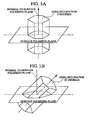
- the inclination of the (0001) plane of crystal grains relative to the normal of the surface polishing plane is measured by emitting an electron beam onto individual ⁇ -Al 2 O 3 crystal grains having a hexagonal crystal lattice present within the measuring range of the surface polishing plane using a field emission scanning electron microscope.
- the measured inclinations within the range of 0-45 degrees indicated by the individual crystal grains are divided for each pitch of 0.25 degrees, and a pole plot graph is prepared in which the measured inclinations present in each section are tabulated for each section.
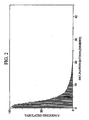
- the pole plot graph is shown in which the highest peak of the inclination division appears within a narrow range of 0-10 degrees.
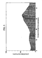
- a conventional ⁇ -Al 2 O 3 layer was confirmed to have a pole plot graph in which a gradual highest pitch of the inclination section appears over a wide range of 25-35 degrees.
- the present invention is based on these research results.
- the present invention provides a cutting tool provided with a tool base composed with WC-based cemented carbide or TiCN-based Cermet, and a hard coating layer; wherein the hard coating layer comprises:
- the ⁇ -Al 2 O 3 layer which composes the hard coating layer, exhibits a pole plot graph in which the highest peak appears in the inclination section within a range of 0-10 degrees as shown in Fig. 2, and demonstrates superior chipping resistance.
- the cutting tool of the present invention exhibits superior wear resistance and cutting performance over a long period of time even during high-speed intermittent cutting of various types of steel and cast iron that is accompanied by extremely high levels of mechanical and thermal shock as well as the generation of a large amount of heat.
- the hard coating layer it is preferable for the hard coating layer to have an aluminum oxide core thin layer containing an aluminum oxide core between the lower layer and the upper layer.
- the mean layer thickness of the aluminum oxide core thin layer prefferably be in a range of 20-200 nm.
- the hard coating layer is obtained by forming the Ti compound and/or Zr compound layer; forming the aluminum oxide core thin layer on the surface of the Ti compound and/or Zr compound layer under conditions of a reaction gas composition, in % by volume, of AlCl 3 : 3-10%, CO 2 : 0.5-3%, C 2 H 4 : 0.01-0.3% and H 2 : remainder, a reaction atmosphere temperature of 750-900°C and a reaction atmosphere pressure of 3-13 kPa; and heating the aluminum oxide core thin layer to 1100-1200°C under conditions in which the reaction atmosphere is hydrogen and the reaction pressure is 3-13 kPa; and forming the aluminum oxide layer having an a crystal structure on the heated aluminum oxide core thin layer.
- a reaction gas composition in % by volume, of AlCl 3 : 3-10%, CO 2 : 0.5-3%, C 2 H 4 : 0.01-0.3% and H 2 : remainder, a reaction atmosphere temperature of 750-900°C and a reaction atmosphere pressure of 3-13 kP
- the cutting tool of the present invention is provided with a tool base composed with WC-based cemented carbide or TiCN-based Cermet, and a hard coating layer.
- the hard coating layer further comprises a Ti compound and/or Zr compound layer, which is a lower layer, and an ⁇ -Al 2 O 3 layer, which is an upper layer.
- the Ti compound and/or Zr compound layer is basically present as the lower layer of the ⁇ -Al 2 O 3 layer. Since it has superior strength, the hard coating layer comprising it also has superior strength. In addition, since it is securely adhered to both the tool base and the ⁇ -Al 2 O 3 layer, it contributes to improved adhesion of the hard coating layer to the tool base. If the mean layer thickness is less than 0.5 ⁇ m, the actions are unable to be fully demonstrated. On the other hand, if the mean layer thickness exceeds 20 ⁇ m, the thermoplastic deformation occurs easily during high-speed intermittent cutting accompanying the generation of high levels of heat, in particular, thereby causing uneven wear. Consequently, the mean layer thickness of the Ti compound and/or Zr compound layer is defined to be 0.5-20 ⁇ m.
- the ⁇ -Al 2 O 3 layer improves wear resistance of the hard coating layer because Al 2 O 3 itself has high hardness and superior heat resistance.
- the ⁇ -Al 2 O 3 layer of the present invention since the ⁇ -Al 2 O 3 layer of the present invention has superior strength as compared with conventional ⁇ -Al 2 O 3 layers, it acts to further improve the chipping resistance of the hard coating layer.
- the effects are unable to be adequately demonstrated if its mean layer thickness is less than 1 ⁇ m. On the other hand, if it is thicker than 30 ⁇ m, chipping occurs easily. Consequently, the mean layer thickness of the ⁇ -Al 2 O 3 layer is defined to be 1-30 ⁇ m.
- Its mean layer thickness is preferably 20 nm or more, and more preferably 30 nm or more.
- its mean layer thickness is preferably 200 nm or less, and more preferably 150 nm or less.
- the mean layer thickness of the Al 2 O 3 core thin film formed on the Ti compound and/or Zr compound layer prior to formation by vapor deposition of the ⁇ -Al 2 O 3 layer is preferably 20-200 nm, and more preferably 30-150 nm.
- a TiN layer having a gold color tone may also be formed by vapor deposition as necessary as the uppermost surface layer of the hard coating layer for the purpose of discriminating before and after use of the coated Cermet cutting tool.
- the mean layer thickness of the TiN layer having a gold color tone is preferably 0.1-1 ⁇ m. If the mean layer thickness is less than 0.1 ⁇ m, adequate discrimination effects are unable to be obtained. In addition, a mean layer thickness of up to 1 ⁇ m is adequate for the TiN layer to demonstrate a discrimination effect.
- WC powder, TiC powder, ZrC powder, VC powder, TaC powder, NbC powder, Cr 3 C 2 powder, TiN powder, TaN powder and Co powder having a mean particle diameter of 1-3 ⁇ m were prepared. These raw material powders were blended to the blending compositions shown in Table 1, wax was added to them, and they were then mixed using a ball mill for 24 hours in acetone. After drying under reduced pressure, the dried mixtures were pressed formed into green compacts of a predetermined shape at a pressure of 98 MPa. Next, the green compacts were vacuum sintered for 1 hour in a vacuum at 5 Pa at a predetermined temperature within the range of 1370-1470°C.
- Mo 2 C powder Mo 2 C powder
- ZrC powder ZrC powder
- NbC powder NbC powder
- TaC powder WC powder
- Co powder and Ni powder having a mean particle diameter of 0.5-2 ⁇ m were prepared. These powders were mixed to the blending compositions shown in Table 2, they were then wet-mixed for 24 hours with a ball mill. After drying, they were press formed into green compacts at a pressure of 98 MPa. Next, the green compacts were sintered for 1 hour at a nitrogen atmosphere at 1.3 kPa, at a temperature of 1540°C.
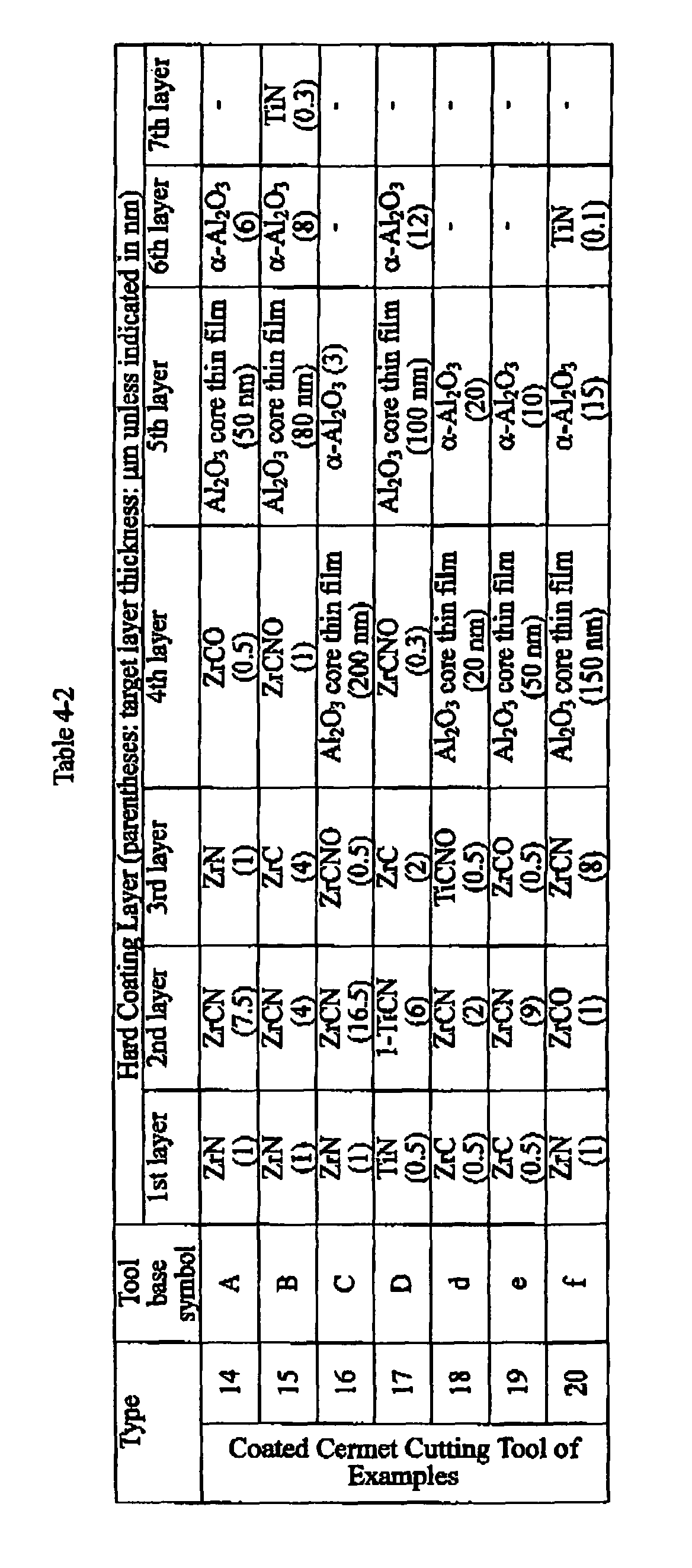
- the Ti compound and/or Zr compound layers having the target layer thicknesses shown in Table 4 were first formed by vapor deposition as the lower layer of the hard coating layer under the conditions shown in Table 3 (the 1-TiCN in Table 3 indicates the formation conditions of a TiCN layer having a longitudinally growing crystal structure described in Japanese Unexamined Patent Application, First Publication No. Hei 6-8010, while others indicate the formation conditions of an ordinary particulate crystal structure) using an ordinary chemical vapor deposition device on the surfaces of these tool bases A through F and a through f.
- Al 2 O 3 core thin films of the target layer thicknesses shown in Table 4 were formed under low-temperature conditions in which a reaction gas composition comprising, in % by volume, AlCl 3 : 6.5%, CO 2 : 1.6%, C 2 H 4 : 0.13%, and H 2 : reminder; a reaction atmosphere temperature: 820°C; a reaction atmosphere pressure: 8 kPa; and a reaction time: 5-80 minutes (the relationship between the layer thickness of the Al 2 O 3 core thin film and a reaction time was assessed in advance by an experiment, similar to the case of the Ti compound layer).
- the Al 2 O 3 core thin film was heat treated under conditions of changing the reaction atmosphere pressure to a hydrogen atmosphere at 8 kPa and raising the reaction atmosphere temperature to 1135°C.
- cutting tools of Examples 1, 3-6 and 8-11, 14, 16-19 were produced by forming by vapor deposition the ⁇ -Al 2 O 3 layers of the target layer thicknesses shown in Table 4 for the upper layer of the hard coating layer under the conditions shown in the Table 3.
- cutting tools of Examples 2, 7, 12, 13, 15 and 20 were produced by forming by vapor deposition the TiN layers of the target layer thicknesses shown in Table 4 for the uppermost surface layer of the hard coating layer under the conditions shown in the Table 3 on the resulting ⁇ -Al 2 O 3 layers.
- comparative cutting tools 1 through 20 were respectively produced under the same conditions with the exception of not forming the Al 2 O 3 core thin film and not performing heat treatment prior to forming the ⁇ -Al 2 O 3 layer of the hard coating layer as shown in Table 5.
- Pole plot graphs were respectively produced using a field emission scanning electron microscope for the ⁇ -Al 2 O 3 layers that compose the hard coating layer with the resulting coated Cermet cutting tools of Examples 1-20 and coated Cermet cutting tools of Comparative Examples 1-20.
- the surface of the ⁇ -Al 2 O 3 layer was placed inside the barrel of a field emission scanning electron microscope as the polishing plane.
- an electron beam having an acceleration voltage of 15 kV was emitted onto individual crystal grains having a hexagonal crystal lattice present within the measuring range of the surface polishing plane at an emission current of 1 nA and incident angle of 70 degrees relative to the polishing plane.
- Inclination of the (0001) plane which is the crystal plane of the crystal grains, was measured relative to the normal of the surface polishing plane in intervals of 0.1 ⁇ m/step for a region measuring 30 x 50 ⁇ m using an electron backscattering diffraction imaging device.
- the measured inclination within the range of 0-45 degrees indicated by each crystal grain was divided for each pitch of 0.25 degrees based on the measurement results, and the measured inclinations present in each section were tabulated for each section to prepare pole plot graphs.
- the thickness of each layer of the hard coating layers of the resulting coated Cermet cutting tools of Examples 1-20 and Comparative Examples 1-20 was measured using a scanning electron microscope (measurement of longitudinal cross-section). As a result, all of the mean layer thicknesses (average of five measuring points) were confirmed to be substantially the same as the target layer thickness. Furthermore, measurement of the layer thickness of the heat-treated Al 2 O 3 core thin film in the coated Cermet cutting tools of Examples 1-20 was extremely difficult.
- coated Cermet cutting tools of Examples 1-7 and 14-17 and coated Cermet coating tools of Comparative Examples 1-7 and 14-17 were bolted onto the end of a tool steel cutting bit followed by performing the cutting tests described below.
- Cut material Round bar composed of JIS-SCM440 in which four longitudinal grooves are formed at equal intervals in the direction of length
- Cutting speed 350 m/min (normal cutting speed: 250 m/min)
- Cutting depth 1 mm Feed: 0.25 mm/rev.
- Cutting time 5 min.
- Cut material Round bar composed of JIS-S45C in which four longitudinal grooves are formed at equal intervals in the direction of length Cutting speed; 400 m/min (normal cutting speed: 300 m/min) Cutting depth: 1 mm Feed: 0.25 mm/rev. Cutting time: 5 min.
- Cut material Round bar composed of JIS-FC300 in which four longitudinal grooves are formed at equal intervals in the direction of length
- Cutting speed 450 m/min (normal cutting speed: 300 m/min)
- Cutting depth 1.5 mm
- Feed 0.25 mm/rev.
- Cutting time 5 min.
- coated Cermet cutting tools of Examples 8-13 and 18-20 and the coated Cermet cutting tools of Comparative Examples 8-13 and 18-20 were bolted to the end of the tool steel cutting bit followed by performing the cutting tests described below.
- Cut material Round bar composed of JIS-SCM440 in which four longitudinal grooves are formed at equal intervals in the direction of length
- Cutting speed 400 m/min (normal cutting speed: 250 m/min)
- Cutting depth 0.7 mm
- Feed 0.15 mm/rev.
- Cutting time 5 min.
- Cut material Round bar composed of JIS-S45C in which four longitudinal grooves are formed at equal intervals in the direction of length
- Cutting speed 400 m/min (normal cutting speed: 300 m/min)
- Cutting depth 0.7 mm
- Feed 0.15 mm/rev.
- Cutting time 5 min.
- Cut material Round bar composed of JIS-FC300 in which four longitudinal grooves are formed at equal intervals in the direction of length
- Cutting speed 450 m/min (normal cutting speed: 300 m/min)
- Cutting depth 0.7 mm
- Feed 0.15 mm/rev.
- Cutting time 5 min.
- the (0001) plane of the ⁇ -Al 2 O 3 layer indicated the highest peak in the inclination section within the range of 0-10 degrees in the pole plot graphs. Consequently, these cutting tools demonstrated extremely high resistance to mechanical and thermal shock, and superior chipping resistance even during high-speed intermittent cutting of steel or cast iron accompanied by the generation of a large amount of heat.
- the cutting tools significantly suppressed the occurrence of chipping of the cutting edge, and exhibited superior wear resistance.
- the cutting tool of the present invention is naturally capable of continuous and intermittent cutting of various types of steel and cast iron under normal conditions, is extremely resistant to mechanical and thermal shock, exhibits superior chipping resistance even during the most severe high-speed intermittent cutting accompanied the generation of a large amount of heat, and demonstrates superior cutting performance over a long period of time.
- the cutting tool of the present invention is capable of satisfactorily accommodating increased performance of cutting devices, labor and energy savings in cutting processing, as well as reductions in costs.
Landscapes
- Chemical & Material Sciences (AREA)
- Engineering & Computer Science (AREA)
- Mechanical Engineering (AREA)
- Metallurgy (AREA)
- Materials Engineering (AREA)
- Chemical Kinetics & Catalysis (AREA)
- Organic Chemistry (AREA)
- Inorganic Chemistry (AREA)
- General Chemical & Material Sciences (AREA)
- General Engineering & Computer Science (AREA)
- Ceramic Engineering (AREA)
- Cutting Tools, Boring Holders, And Turrets (AREA)
- Chemical Vapour Deposition (AREA)
- Auxiliary Devices For Machine Tools (AREA)
Abstract

Description
| Type | Blending Composition (% by mass) | ||||||||||
| Co | TiC | ZrC | VC | TaC | NbC Cr3C2 | TiN | TaN | WC | |||
| Tool Base | A | 7 | - | - | - | - | - | - | - | - | Rem. |
| B | 5.7 | - | - | - | 1.5 | 0.5 | - | - | - | Rem. | |
| C | 5.7 | - | - | - | - | - | 1 | - | - | Rem. | |
| D | 8.5 | - | 0.5 | - | - | - | 0.5 | - | - | Rem. | |
| E | 12.5 | 2 | - | - | - | - | - | 1 | 2 | Rem. | |
| F | 14 | - | - | 0.2 | - | - | 0.8 | - | - | Rem. |
| Type | Blending Composition (% by mass) | ||||||||
| Co | Ni | ZrC | TaC | NbC | Mo2C | WC | TiCN | ||
| Tool Base | a | 13 | 5 | - | 10 | - | 10 | 16 | Rem. |
| b | 8 | 7 | - | 5 | - | 7.5 | - | Rem. | |
| c | 5 | - | - | - | - | 6 | 10 | Rem. | |
| | 10 | 5 | - | 11 | 2 | - | - | Rem. | |
| e | 9 | 4 | 1 | 8 | - | 10 | 10 | Rem. | |
| f | 12 | 5.5 | - | 10 | - | 9.5 | 14.5 | Rem. |



| Inclination section in which (0001) plane of α-Al2O3 layer indicates highest peak (degrees) | Amount of flank wear (mm) | ||||
| Alloy steel | Carbon steel | Cast iron | |||
| Coated Cermet Cutting Tool of Examples | 1 | 3.25-3.50 | 0.31 | 0.30 | 0.33 |
| 2 | 1.00-1.25 | 0.23 | 0.24 | 0.25 | |
| 3 | 1.50-1.75 | 0.26 | 0.25 | 0.24 | |
| 4 | 2.75-3.00 | 0.32 | 0.31 | 0.34 | |
| 5 | 8.00-8.25 | 0.38 | 0.36 | 0.35 | |
| 6 | 2.00-2.25 | 0.28 | 0.28 | 0.29 | |
| 7 | 5.25-5.50 | 0.33 | 0.34 | 0.37 | |
| 8 | 9.75-10.00 | 0.37 | 0.36 | 0.36 | |
| 9 | 2.25-2.50 | 0.29 | 0.29 | 0.31 | |
| 10 | 0.50-0.75 | 0.23 | 0.21 | 0.21 | |
| 11 | 3.50-3.75 | 0.38 | 0.39 | 0.45 | |
| 12 | 4.25-4.50 | 0.34 | 0.33 | 0.33 | |
| 13 | 0.00-0.25 | 0.25 | 0.20 | 0.19 | |
| 14 | 3.00-3.25 | 0.30 | 0.32 | 0.31 | |
| 15 | 1.50-1.75 | 0.24 | 0.25 | 0.26 | |
| 16 | 1.00-1.25 | 0.26 | 0.24 | 0.26 | |
| 17 | 2.75-3.00 | 0.32 | 0.30 | 0.33 | |
| 18 | 8.50-8.75 | 0.39 | 0.38 | 0.36 | |
| 19 | 1.50-1.75 | 0.25 | 0.26 | 0.27 | |
| 20 | 5.00-5.25 | 0.34 | 0.32 | 0.35 |
| Inclination section in which (0001) plane of α-Al2O3 layer indicates highest peak (degrees) | Cutting test results (time to reach service life) | ||||
| Alloy steel | Carbon steel | Cast iron | |||
| Coated Cermet Cutting Tool of Comparative Examples | 1 | 25.75-26.00 | 2.8 min. | 2.7 min. | 2.9 min. |
| 2 | 29.50-29.75 | 1.7 min. | 1.5 min. | 1.0 min. | |
| 3 | 33.50-33.75 | 0.5 min. | 0.3 min. | 0.3 min. | |
| 4 | 26.50-26.75 | 2.7 min. | 2.9 min. | 3.0 min. | |
| 5 | 32.25-32.50 | 0.5 min. | 0.4 min. | 0.5 min. | |
| 6 | 29.50-29.15 | 1.5 min. | 1.8 min. | 1.9 min. | |
| 7 | 27.50-27.75 | 2.0 min. | 2.1 min. | 1.6 min. | |
| 8 | 31.00-31.25 | 0.9 min. | 0.7 min. | 0.6 min. | |
| 9 | 26.25-26.50 | 2.2 min. | 1.9 min. | 1.9 min. | |
| 10 | 33.25-33.50 | 0.3 min. | 0.3 min. | 0.5 min. | |
| 11 | 25.00-25.25 | 3.1 min. | 2.6 min. | 1.5 min. | |
| 12 | 31.50-31.75 | 1.1 min. | 0.8 min. | 0.8 min. | |
| 13 | 34.75-35.00 | 0.2 min. | 0.3 min. | 0.5 min. | |
| 14 | 25.75-26.00 | 2.9 min. | 2.8 min. | 2.7 min. | |
| 15 | 29.00-29.25 | 1.8 min. | 1.7 min. | 1.2 min. | |
| 16 | 32.50-32.75 | 0.8 min. | 0.5 min. | 0.9 min. | |
| 17 | 28.50-28.75 | 2.5 min. | 2.8 min. | 3.0 min. | |
| 18 | 34.25-34.50 | 0.5 min. | 0.3 min. | 0.7 min. | |
| 19 | 29.25-29.50 | 1.7 min. | 1.8 min. | 2.0 min. | |
| 20 | 27.75-28.00 | 2.2 min. | 1.9 min. | 1.8 min. | |
| (In the table, service life was reached due to the occurrence of chipping in the hard coating layer.) |
Cut material: Round bar composed of JIS-SCM440 in which four longitudinal grooves are formed at equal intervals in the direction of length
Cutting speed: 350 m/min (normal cutting speed: 250 m/min)
Cutting depth: 1 mm
Feed: 0.25 mm/rev.
Cutting time: 5 min.
Cutting speed; 400 m/min (normal cutting speed: 300 m/min)
Cutting depth: 1 mm
Feed: 0.25 mm/rev.
Cutting time: 5 min.
Cutting speed: 450 m/min (normal cutting speed: 300 m/min)
Cutting depth: 1.5 mm
Feed: 0.25 mm/rev.
Cutting time: 5 min.
Cutting speed: 400 m/min (normal cutting speed: 250 m/min)
Cutting depth: 0.7 mm
Feed: 0.15 mm/rev.
Cutting time: 5 min.
Cutting speed: 400 m/min (normal cutting speed: 300 m/min)
Cutting depth: 0.7 mm
Feed: 0.15 mm/rev.
Cutting time: 5 min.
Cutting speed: 450 m/min (normal cutting speed: 300 m/min)
Cutting depth: 0.7 mm
Feed: 0.15 mm/rev.
Cutting time: 5 min.
Claims (4)
- A cutting tool provided with a tool base composed with tungsten carbide-based cemented carbide or titanium carbonitride-based Cermet, and a hard coating layer provided on the surface of the tool base; wherein the bard coating layer comprises:(a) a Ti compound and/or Zr compound layer, which is a lower layer, comprising one or more layers of a Ti carbide layer, Ti nitride layer, Ti carbonitride layer, Ti oxicarbide layer, Ti oxicarbonitride layer, Zr carbide layer, Zr nitride layer, Zr carbonitride layer, Zr oxicarbide layer and Zr oxicarbonitride layer formed by chemical vapor deposition, and having an overall mean layer thickness of 0.5-20 µm, and(b) an aluminum oxide layer having an α crystal structure in the state of being formed by chemical vapor deposition, which is an upper layer, comprising the highest peak in the inclination section within a range of 0-10 degrees in the case of emitting an electron beam onto individual crystal grains having a hexagonal crystal lattice present within the measuring range of the surface polishing plane, measuring the inclination of the (0001) crystal plane of the crystal grains relative to the normal of the surface polishing plane using a field emission scanning electron microscope, dividing the measured inclinations within a range of 0-45 degrees indicated by the individual crystal grains for each pitch of 0.25 degrees, and preparing a pole plot graph by tabulating the measured inclinations present in each section for each section, and having the mean layer thickness is 1-30 µm.
- A cutting tool according to claim 1, wherein the hard coating layer has an aluminum oxide core thin layer containing an aluminum oxide core between the lower layer and the upper layer.
- A cutting tool according to claim 1, wherein the mean layer thickness of the aluminum oxide core thin layer is 20-200 nm.
- A cutting tool according to claim 2, wherein the hard coating layer is obtained by forming the Ti compound and/or Zr compound layer;
forming the aluminum oxide core thin layer on the surface of the Ti compound and/or Zr compound layer under conditions of a reaction gas composition, in % by volume, of AlCl3: 3-10%, CO2: 0.5-3%, C2H4: 0.01-0.3% and H2: remainder, a reaction atmosphere temperature of 750-900°C and a reaction atmosphere pressure of 3-13 kPa; and
heating the aluminum oxide core thin layer to 1100-1200°C under conditions in which the reaction atmosphere is hydrogen and the reaction pressure is 3-13 kPa; and
forming the aluminum oxide layer having an α crystal structure on the heated aluminum oxide core thin layer.
Applications Claiming Priority (4)
| Application Number | Priority Date | Filing Date | Title |
|---|---|---|---|
| JP2003053059 | 2003-02-28 | ||
| JP2003053059 | 2003-02-28 | ||
| JP2003056639 | 2003-03-04 | ||
| JP2003056639 | 2003-03-04 |
Publications (3)
| Publication Number | Publication Date |
|---|---|
| EP1479791A2 true EP1479791A2 (en) | 2004-11-24 |
| EP1479791A3 EP1479791A3 (en) | 2006-06-21 |
| EP1479791B1 EP1479791B1 (en) | 2008-01-30 |
Family
ID=33100338
Family Applications (1)
| Application Number | Title | Priority Date | Filing Date |
|---|---|---|---|
| EP04004292A Expired - Lifetime EP1479791B1 (en) | 2003-02-28 | 2004-02-26 | Cutting tool |
Country Status (7)
| Country | Link |
|---|---|
| US (2) | US7201956B2 (en) |
| EP (1) | EP1479791B1 (en) |
| JP (1) | JP2004284003A (en) |
| KR (1) | KR100993152B1 (en) |
| CN (1) | CN100430170C (en) |
| AT (1) | ATE385266T1 (en) |
| DE (1) | DE602004011582T2 (en) |
Cited By (14)
| Publication number | Priority date | Publication date | Assignee | Title |
|---|---|---|---|---|
| EP1626105A1 (en) * | 2004-08-11 | 2006-02-15 | Mitsubishi Materials Corporation | Surface-coated cermet cutting tool with hard coating layer having excellent chipping resistance in high-speed intermittent cutting work |
| EP1683893A1 (en) * | 2005-01-21 | 2006-07-26 | Mitsubishi Materials Corporation | Surface-coated cermet cutting tool with hard coating layer exhibiting excellent chipping resistance in high-speed intermittent cutting I |
| EP1723266A1 (en) * | 2004-03-12 | 2006-11-22 | Kennametal, Inc. | Alumina coating, coated product and method of making the same |
| WO2009011648A1 (en) * | 2007-07-13 | 2009-01-22 | Seco Tools Ab | Textured alpha- alumina coated cutting tool insert for turning of steel |
| EP2098612A2 (en) | 2008-03-07 | 2009-09-09 | SECO TOOLS AB; (publ) | Oxide coated cutting insert |
| WO2009110830A1 (en) | 2008-03-07 | 2009-09-11 | Seco Tools Ab | Oxide coated cutting inser |
| EP2141257A2 (en) | 2008-03-07 | 2010-01-06 | Seco Tools Ab | Oxide coated cutting insert |
| EP2186927A1 (en) * | 2008-11-07 | 2010-05-19 | Masco Corporation | Coated article with black color |
| US8409732B2 (en) | 2008-03-07 | 2013-04-02 | Seco Tools Ab | Oxide coated cutting insert |
| EP2818573B1 (en) | 2013-06-27 | 2016-02-03 | Sandvik Intellectual Property AB | Coated cutting tool |
| EP2570510B1 (en) | 2011-09-16 | 2016-03-30 | Walter AG | Sulfur containing alpha-alumina coated cutting tool |
| EP2570511B1 (en) | 2011-09-16 | 2019-03-20 | Walter AG | Grain boundary engineered alpha-alumina coated cutting tool |
| EP3848485A1 (en) | 2020-01-10 | 2021-07-14 | Sakari Ruppi | Improved alpha alumina layer deposited with controlled textures |
| EP3848484A2 (en) | 2020-01-10 | 2021-07-14 | Sakari Ruppi | Improved alumina layer deposited at low temperature |
Families Citing this family (55)
| Publication number | Priority date | Publication date | Assignee | Title |
|---|---|---|---|---|
| EP1536041B1 (en) * | 2003-11-25 | 2008-05-21 | Mitsubishi Materials Corporation | Coated cermet cutting tool with a chipping resistant, hard coating layer |
| US7273665B2 (en) * | 2003-12-22 | 2007-09-25 | Mitsubishi Materials Corporation | Surface-coated cermet cutting tool with hard coating layer having excellent chipping resistance |
| SE528695C2 (en) * | 2004-12-22 | 2007-01-23 | Sandvik Intellectual Property | Tool holder for chip separating machining |
| SE528670C2 (en) * | 2004-12-22 | 2007-01-16 | Sandvik Intellectual Property | Cut coated with a transparent paint layer |
| DE102004063816B3 (en) * | 2004-12-30 | 2006-05-18 | Walter Ag | Cutting plate for a cutting tool comprises a wear-reducing coating consisting of a multiple layer base layer, an aluminum oxide multiple layer and a two-layer covering layer |
| JP4793749B2 (en) * | 2005-04-14 | 2011-10-12 | 三菱マテリアル株式会社 | Surface-coated cermet cutting tool whose hard coating layer exhibits excellent chipping resistance in high-speed intermittent cutting |
| JP4793750B2 (en) * | 2005-04-19 | 2011-10-12 | 三菱マテリアル株式会社 | Surface coated cermet cutting tool with excellent chipping resistance in high-speed intermittent cutting of hard steel with excellent hard coating layer |
| CN1298665C (en) * | 2005-07-08 | 2007-02-07 | 清华大学 | Nano Co-Al2O3 composite ceramic cutting tool and its preparation method |
| SE529051C2 (en) * | 2005-09-27 | 2007-04-17 | Seco Tools Ab | Cutting tool inserts coated with alumina |
| CN1966264B (en) * | 2005-11-18 | 2012-07-04 | 三菱麻铁里亚尔株式会社 | Surface coated cutting tool made of cermet |
| WO2008082020A1 (en) * | 2007-01-02 | 2008-07-10 | Taegutec Ltd. | Surface treating method for cutting tools |
| JP5262545B2 (en) * | 2007-10-29 | 2013-08-14 | 日立電線株式会社 | Nitride semiconductor free-standing substrate and device using the same |
| JP5187570B2 (en) * | 2007-12-28 | 2013-04-24 | 三菱マテリアル株式会社 | Surface coated cutting tool with excellent wear resistance due to hard coating layer |
| TWI510361B (en) * | 2008-04-29 | 2015-12-01 | 新加坡科技研究局 | Inorganic multilayer barrier film and preparation method thereof |
| JP5187571B2 (en) * | 2008-06-20 | 2013-04-24 | 三菱マテリアル株式会社 | Surface coated cutting tool with excellent wear resistance due to hard coating layer |
| JP5383259B2 (en) * | 2009-03-10 | 2014-01-08 | 京セラ株式会社 | Cutting tools |
| SE533972C2 (en) | 2009-07-27 | 2011-03-15 | Seco Tools Ab | Fine-grained cemented carbide cutting tool for turning in hardened steel and tool steel |
| EP2495057B1 (en) | 2009-10-30 | 2017-03-29 | Mitsubishi Materials Corporation | Surface coated cutting tool with excellent chip resistance |
| US8323783B2 (en) * | 2009-11-10 | 2012-12-04 | Kennametal Inc. | Coated cutting insert and method for making the same |
| US8668982B2 (en) | 2009-11-10 | 2014-03-11 | Kennametal Inc. | Coated cutting insert and method for making the same |
| JP5499650B2 (en) * | 2009-11-16 | 2014-05-21 | 三菱マテリアル株式会社 | Diamond-coated tools with excellent peeling and wear resistance |
| JP2011152602A (en) * | 2010-01-27 | 2011-08-11 | Mitsubishi Materials Corp | Surface-coated cutting tool provided with hard coated layer demonstrating superior chipping resistance |
| EP2395126A1 (en) | 2010-06-08 | 2011-12-14 | Seco Tools AB | Textured alumina layer |
| CN102294856A (en) * | 2010-06-28 | 2011-12-28 | 比亚迪股份有限公司 | Decoration material and preparation method thereof |
| JP5464494B2 (en) * | 2010-07-09 | 2014-04-09 | 三菱マテリアル株式会社 | Surface coated cutting tool with excellent chipping resistance and peeling resistance of hard coating layer |
| JP5246518B2 (en) * | 2010-09-15 | 2013-07-24 | 三菱マテリアル株式会社 | Surface coated cutting tool with excellent toughness and chipping resistance due to hard coating layer |
| EP2446988A1 (en) | 2010-10-29 | 2012-05-02 | Seco Tools AB | Cutting tool insert with an alpha-alumina layer having a multi-components texture |
| WO2012079769A1 (en) | 2010-12-17 | 2012-06-21 | Seco Tools Ab | Coated cubic boron nitride tool for machining applications |
| JP5818159B2 (en) * | 2011-02-03 | 2015-11-18 | 三菱マテリアル株式会社 | Surface coated cutting tool with excellent chipping resistance and chipping resistance with excellent hard coating layer |
| JP5257535B2 (en) * | 2011-08-31 | 2013-08-07 | 三菱マテリアル株式会社 | Surface coated cutting tool |
| JP5831704B2 (en) * | 2012-03-06 | 2015-12-09 | 三菱マテリアル株式会社 | Surface coated cutting tool with excellent chipping resistance and chipping resistance with excellent hard coating layer |
| JP5850404B2 (en) * | 2012-03-14 | 2016-02-03 | 三菱マテリアル株式会社 | WC-based cemented carbide cutting tool insert |
| CN103372764B (en) * | 2012-04-20 | 2017-03-01 | 三菱综合材料株式会社 | Hard coating layer plays the excellent resistance to surface-coated cutting tool collapsing knife |
| JP5892472B2 (en) * | 2012-06-19 | 2016-03-23 | 三菱マテリアル株式会社 | A surface-coated cutting tool with a hard coating layer that exhibits excellent peeling and chipping resistance in high-speed intermittent cutting. |
| JP5892380B2 (en) * | 2012-06-29 | 2016-03-23 | 三菱マテリアル株式会社 | Surface-coated cutting tool that exhibits excellent chipping resistance and wear resistance with a hard coating layer in high-speed intermittent cutting |
| WO2014153469A1 (en) | 2013-03-21 | 2014-09-25 | Kennametal Inc. | Coatings for cutting tools |
| US9371580B2 (en) | 2013-03-21 | 2016-06-21 | Kennametal Inc. | Coated body wherein the coating scheme includes a coating layer of TiAl2O3 and method of making the same |
| DE112014001562B4 (en) * | 2013-03-21 | 2019-08-08 | Kennametal Inc. | Coatings for cutting tools |
| US10286453B2 (en) | 2014-01-30 | 2019-05-14 | Sandvik Intellectual Property Ab | Alumina coated cutting tool |
| EP2902528B1 (en) | 2014-01-30 | 2016-06-29 | Walter Ag | Alumina coated cutting tool with zigzag alumina grain boundaries |
| JP6657594B2 (en) * | 2014-05-16 | 2020-03-04 | 三菱マテリアル株式会社 | Surface coated cutting tool |
| JP6548072B2 (en) * | 2014-05-30 | 2019-07-24 | 三菱マテリアル株式会社 | Surface coated cutting tool |
| US9719175B2 (en) | 2014-09-30 | 2017-08-01 | Kennametal Inc. | Multilayer structured coatings for cutting tools |
| JP6634647B2 (en) * | 2014-11-27 | 2020-01-22 | 三菱マテリアル株式会社 | Surface coated cutting tool with excellent chipping and wear resistance |
| US9834845B2 (en) | 2015-08-28 | 2017-12-05 | Sumitomo Electric Hardmetal Corp. | Surface-coated cutting tool |
| EP3296044B1 (en) | 2015-08-28 | 2019-10-02 | Sumitomo Electric Hardmetal Corp. | Surface-coated cutting tool |
| CN106856658B (en) * | 2015-10-09 | 2019-03-08 | 住友电工硬质合金株式会社 | Surface-coated cutting tools |
| CN108129167B (en) * | 2018-01-09 | 2020-07-28 | 中南大学 | High-temperature-resistant ablation-resistant modified ZrC-SiC ceramic coating and preparation method thereof |
| KR102531904B1 (en) | 2018-10-15 | 2023-05-11 | 스미또모 덴꼬오 하드메탈 가부시끼가이샤 | cutting tool |
| US11167355B2 (en) | 2018-10-15 | 2021-11-09 | Sumitomo Electric Hardmetal Corp. | Cutting tool |
| WO2020170571A1 (en) | 2019-02-19 | 2020-08-27 | 住友電工ハードメタル株式会社 | Cutting tool |
| CN113226602B (en) | 2019-02-19 | 2024-04-09 | 住友电工硬质合金株式会社 | Cutting Tools |
| WO2020250625A1 (en) | 2019-06-11 | 2020-12-17 | 住友電工ハードメタル株式会社 | Cutting tool |
| CN111893421A (en) * | 2020-08-12 | 2020-11-06 | 常熟市绿一电器配件制造有限公司 | Wear-resistant mold surface nanocrystal pattern layer and preparation method thereof |
| CN117165919A (en) * | 2023-08-30 | 2023-12-05 | 成都工具研究所有限公司 | Composite CVD coating and preparation method and application thereof |
Family Cites Families (22)
| Publication number | Priority date | Publication date | Assignee | Title |
|---|---|---|---|---|
| SE464818B (en) * | 1989-06-16 | 1991-06-17 | Sandvik Ab | COVERED SHOULD BE CUTTING |
| DE69007885T2 (en) * | 1989-07-13 | 1994-07-28 | Seco Tools Ab | Carbide body coated with several oxides and process for its production. |
| DE69010293T3 (en) | 1989-09-04 | 1999-04-22 | Nippon Hardmetal Co. Ltd., Tokio/Tokyo | Ceramic-coated cemented carbide tool with high breaking resistance. |
| JP3052586B2 (en) | 1992-06-25 | 2000-06-12 | 三菱マテリアル株式会社 | Surface-coated tungsten carbide based cemented carbide cutting tool with excellent chipping resistance |
| JP2867803B2 (en) | 1992-06-25 | 1999-03-10 | 三菱マテリアル株式会社 | Surface-coated tungsten carbide based cemented carbide cutting tool with excellent chipping resistance |
| JP3291775B2 (en) | 1992-07-10 | 2002-06-10 | 三菱マテリアル株式会社 | Surface coated cutting tool |
| SE501527C2 (en) | 1992-12-18 | 1995-03-06 | Sandvik Ab | Methods and articles when coating a cutting tool with an alumina layer |
| SE502174C2 (en) | 1993-12-23 | 1995-09-04 | Sandvik Ab | Methods and articles when coating a cutting tool with an alumina layer |
| JP2927181B2 (en) | 1994-05-31 | 1999-07-28 | 三菱マテリアル株式会社 | Surface coated tungsten carbide based cemented carbide cutting tool with excellent interlayer adhesion with hard coating layer |
| US5920760A (en) * | 1994-05-31 | 1999-07-06 | Mitsubishi Materials Corporation | Coated hard alloy blade member |
| SE509201C2 (en) | 1994-07-20 | 1998-12-14 | Sandvik Ab | Aluminum oxide coated tool |
| WO1996010658A1 (en) | 1994-10-04 | 1996-04-11 | Sumitomo Electric Industries, Ltd. | Coated hard alloy |
| US5635247A (en) | 1995-02-17 | 1997-06-03 | Seco Tools Ab | Alumina coated cemented carbide body |
| SE514181C2 (en) | 1995-04-05 | 2001-01-15 | Sandvik Ab | Coated carbide inserts for milling cast iron |
| JP3331929B2 (en) | 1997-11-10 | 2002-10-07 | 三菱マテリアル株式会社 | Surface coated cemented carbide cutting tool with excellent chipping resistance with hard coating layer |
| JPH11267903A (en) * | 1998-03-23 | 1999-10-05 | Mitsubishi Materials Corp | Surface coated cemented carbide cutting tool with excellent fracture resistance |
| JP3371796B2 (en) * | 1998-03-23 | 2003-01-27 | 三菱マテリアル株式会社 | Surface coated cemented carbide cutting tool with excellent fracture resistance |
| DE19980940B4 (en) | 1998-04-14 | 2005-05-25 | Sumitomo Electric Industries, Ltd. | Coated carbide cutting tool |
| US6338894B1 (en) | 2000-05-31 | 2002-01-15 | Mitsubishi Materials Corporation | Coated cemented carbide cutting tool member and process for producing the same |
| US6805944B2 (en) | 2001-03-26 | 2004-10-19 | Mitsubishi Materials Corporation | Coated cemented carbide cutting tool |
| US6733874B2 (en) | 2001-08-31 | 2004-05-11 | Mitsubishi Materials Corporation | Surface-coated carbide alloy cutting tool |
| EP2865784A1 (en) | 2002-08-08 | 2015-04-29 | Kabushiki Kaisha Kobe Seiko Sho (Kobe Steel, Ltd.) | Process for producing alumina coating composed mainly of alpha-type crystal structure |
-
2003
- 2003-10-08 JP JP2003349501A patent/JP2004284003A/en not_active Withdrawn
-
2004
- 2004-02-26 AT AT04004292T patent/ATE385266T1/en active
- 2004-02-26 EP EP04004292A patent/EP1479791B1/en not_active Expired - Lifetime
- 2004-02-26 DE DE602004011582T patent/DE602004011582T2/en not_active Expired - Lifetime
- 2004-02-26 US US10/788,969 patent/US7201956B2/en not_active Ceased
- 2004-02-27 KR KR1020040013587A patent/KR100993152B1/en not_active Expired - Lifetime
- 2004-03-01 CN CNB2004100073475A patent/CN100430170C/en not_active Expired - Lifetime
-
2008
- 2008-09-16 US US12/211,244 patent/USRE41111E1/en not_active Expired - Lifetime
Cited By (21)
| Publication number | Priority date | Publication date | Assignee | Title |
|---|---|---|---|---|
| EP1723266A1 (en) * | 2004-03-12 | 2006-11-22 | Kennametal, Inc. | Alumina coating, coated product and method of making the same |
| US7422806B2 (en) | 2004-08-11 | 2008-09-09 | Mitsubishi Materials Corporation | Surface-coated cermet cutting tool with hard coating layer having excellent chipping resistance in high-speed intermittent cutting work |
| EP1626105A1 (en) * | 2004-08-11 | 2006-02-15 | Mitsubishi Materials Corporation | Surface-coated cermet cutting tool with hard coating layer having excellent chipping resistance in high-speed intermittent cutting work |
| EP1683893A1 (en) * | 2005-01-21 | 2006-07-26 | Mitsubishi Materials Corporation | Surface-coated cermet cutting tool with hard coating layer exhibiting excellent chipping resistance in high-speed intermittent cutting I |
| US7985471B2 (en) | 2007-07-13 | 2011-07-26 | Seco Tools Ab | Coated cutting tool |
| WO2009011648A1 (en) * | 2007-07-13 | 2009-01-22 | Seco Tools Ab | Textured alpha- alumina coated cutting tool insert for turning of steel |
| US8043482B1 (en) | 2008-03-07 | 2011-10-25 | Seco Tools Ab | Oxide coated cutting insert |
| US8409731B2 (en) | 2008-03-07 | 2013-04-02 | Seco Tools Ab | Oxide coated cutting insert |
| EP2141257A2 (en) | 2008-03-07 | 2010-01-06 | Seco Tools Ab | Oxide coated cutting insert |
| WO2009110830A1 (en) | 2008-03-07 | 2009-09-11 | Seco Tools Ab | Oxide coated cutting inser |
| EP2098612A2 (en) | 2008-03-07 | 2009-09-09 | SECO TOOLS AB; (publ) | Oxide coated cutting insert |
| US8075743B2 (en) | 2008-03-07 | 2011-12-13 | Seco Tools Ab | Oxide coated cutting insert |
| US8409732B2 (en) | 2008-03-07 | 2013-04-02 | Seco Tools Ab | Oxide coated cutting insert |
| EP2186927A1 (en) * | 2008-11-07 | 2010-05-19 | Masco Corporation | Coated article with black color |
| EP2570510B1 (en) | 2011-09-16 | 2016-03-30 | Walter AG | Sulfur containing alpha-alumina coated cutting tool |
| EP2570510B2 (en) † | 2011-09-16 | 2019-02-13 | Walter AG | Sulfur containing alpha-alumina coated cutting tool |
| EP2570511B1 (en) | 2011-09-16 | 2019-03-20 | Walter AG | Grain boundary engineered alpha-alumina coated cutting tool |
| EP2570511B2 (en) † | 2011-09-16 | 2025-08-06 | Walter AG | Grain boundary engineered alpha-alumina coated cutting tool |
| EP2818573B1 (en) | 2013-06-27 | 2016-02-03 | Sandvik Intellectual Property AB | Coated cutting tool |
| EP3848485A1 (en) | 2020-01-10 | 2021-07-14 | Sakari Ruppi | Improved alpha alumina layer deposited with controlled textures |
| EP3848484A2 (en) | 2020-01-10 | 2021-07-14 | Sakari Ruppi | Improved alumina layer deposited at low temperature |
Also Published As
| Publication number | Publication date |
|---|---|
| DE602004011582T2 (en) | 2008-05-21 |
| US7201956B2 (en) | 2007-04-10 |
| JP2004284003A (en) | 2004-10-14 |
| EP1479791B1 (en) | 2008-01-30 |
| DE602004011582D1 (en) | 2008-03-20 |
| KR100993152B1 (en) | 2010-11-09 |
| CN1524653A (en) | 2004-09-01 |
| CN100430170C (en) | 2008-11-05 |
| USRE41111E1 (en) | 2010-02-09 |
| EP1479791A3 (en) | 2006-06-21 |
| ATE385266T1 (en) | 2008-02-15 |
| KR20040078062A (en) | 2004-09-08 |
| US20040224159A1 (en) | 2004-11-11 |
Similar Documents
| Publication | Publication Date | Title |
|---|---|---|
| USRE41111E1 (en) | Cutting tool | |
| EP1288335B1 (en) | Surface-coated carbide alloy cutting tool | |
| EP2267182B1 (en) | Coated cutting tool | |
| EP1788124B1 (en) | Surface coated cutting tool made of cermet having property-modified alpha type Al2O3 layer of hard coating layer | |
| JP2006198735A (en) | Surface coated cermet cutting tool whose hard coating layer exhibits excellent chipping resistance in high-speed intermittent cutting | |
| JP4512989B2 (en) | Surface coated cermet cutting tool with excellent chipping resistance with hard coating layer | |
| JP5023654B2 (en) | Surface-coated cermet cutting tool with excellent crystal grain interface strength, modified α-type Al2O3 layer of hard coating layer | |
| JP5170828B2 (en) | A surface-coated cutting tool that exhibits excellent chipping resistance with a hard coating layer in high-speed intermittent cutting | |
| JP5176787B2 (en) | Surface coated cutting tool with excellent chipping resistance and wear resistance due to hard coating layer | |
| JP2008093769A (en) | Surface coated cutting tool with excellent chipping resistance due to hard coating layer | |
| JP2004299021A (en) | Surface-coated cermet cutting tool with excellent thermal shock resistance with hard coating layer | |
| JP2006198740A (en) | Surface coated cermet cutting tool whose hard coating layer exhibits excellent chipping resistance in high-speed intermittent cutting | |
| JP3371796B2 (en) | Surface coated cemented carbide cutting tool with excellent fracture resistance | |
| JP4747386B2 (en) | Surface coated cermet cutting tool whose hard coating layer exhibits excellent wear resistance in high speed cutting | |
| JP5187573B2 (en) | Surface-coated cutting tool that exhibits excellent chipping resistance and wear resistance with a hard coating layer in high-speed heavy cutting | |
| JP5170829B2 (en) | Surface coated cutting tool with excellent wear resistance with hard coating layer in high speed cutting | |
| JP4474644B2 (en) | Surface-coated cermet cutting tool whose hard coating layer exhibits excellent chipping resistance in high-speed intermittent cutting | |
| JP4529578B2 (en) | Surface coated cermet cutting tool whose hard coating layer exhibits excellent chipping resistance in high speed heavy cutting | |
| JP2009166195A (en) | A surface-coated cutting tool that exhibits excellent chipping resistance and wear resistance with a hard coating layer in high-speed interrupted cutting | |
| JP2005279909A (en) | Surface coated cermet cutting tool with excellent chipping resistance with hard coating layer | |
| JP4747338B2 (en) | Surface-coated cermet cutting tool that exhibits excellent chipping resistance with a hard coating layer in high-speed cutting of difficult-to-cut materials | |
| JP4747387B2 (en) | Surface-coated cermet cutting tool with excellent chipping resistance thanks to thick α-type aluminum oxide layer | |
| JP2004181554A (en) | Surface-coated cermet cutting tool with excellent thermal shock resistance with hard coating layer | |
| JP4692065B2 (en) | Surface-coated cermet cutting tool with excellent chipping resistance thanks to thick α-type aluminum oxide layer | |
| JP4816904B2 (en) | Surface coated cermet cutting tool whose hard coating layer exhibits excellent wear resistance in high speed cutting |
Legal Events
| Date | Code | Title | Description |
|---|---|---|---|
| PUAI | Public reference made under article 153(3) epc to a published international application that has entered the european phase |
Free format text: ORIGINAL CODE: 0009012 |
|
| AK | Designated contracting states |
Kind code of ref document: A2 Designated state(s): AT BE BG CH CY CZ DE DK EE ES FI FR GB GR HU IE IT LI LU MC NL PT RO SE SI SK TR |
|
| AX | Request for extension of the european patent |
Extension state: AL LT LV MK |
|
| PUAL | Search report despatched |
Free format text: ORIGINAL CODE: 0009013 |
|
| AK | Designated contracting states |
Kind code of ref document: A3 Designated state(s): AT BE BG CH CY CZ DE DK EE ES FI FR GB GR HU IE IT LI LU MC NL PT RO SE SI SK TR |
|
| AX | Request for extension of the european patent |
Extension state: AL LT LV MK |
|
| 17P | Request for examination filed |
Effective date: 20061026 |
|
| 17Q | First examination report despatched |
Effective date: 20061127 |
|
| AKX | Designation fees paid |
Designated state(s): AT BE BG CH CY CZ DE DK EE ES FI FR GB GR HU IE IT LI LU MC NL PT RO SE SI SK TR |
|
| GRAP | Despatch of communication of intention to grant a patent |
Free format text: ORIGINAL CODE: EPIDOSNIGR1 |
|
| GRAS | Grant fee paid |
Free format text: ORIGINAL CODE: EPIDOSNIGR3 |
|
| GRAA | (expected) grant |
Free format text: ORIGINAL CODE: 0009210 |
|
| AK | Designated contracting states |
Kind code of ref document: B1 Designated state(s): AT BE BG CH CY CZ DE DK EE ES FI FR GB GR HU IE IT LI LU MC NL PT RO SE SI SK TR |
|
| REG | Reference to a national code |
Ref country code: GB Ref legal event code: FG4D |
|
| REG | Reference to a national code |
Ref country code: CH Ref legal event code: EP |
|
| REG | Reference to a national code |
Ref country code: IE Ref legal event code: FG4D |
|
| REF | Corresponds to: |
Ref document number: 602004011582 Country of ref document: DE Date of ref document: 20080320 Kind code of ref document: P |
|
| REG | Reference to a national code |
Ref country code: SE Ref legal event code: TRGR |
|
| PG25 | Lapsed in a contracting state [announced via postgrant information from national office to epo] |
Ref country code: LI Free format text: LAPSE BECAUSE OF FAILURE TO SUBMIT A TRANSLATION OF THE DESCRIPTION OR TO PAY THE FEE WITHIN THE PRESCRIBED TIME-LIMIT Effective date: 20080130 Ref country code: FI Free format text: LAPSE BECAUSE OF FAILURE TO SUBMIT A TRANSLATION OF THE DESCRIPTION OR TO PAY THE FEE WITHIN THE PRESCRIBED TIME-LIMIT Effective date: 20080130 Ref country code: ES Free format text: LAPSE BECAUSE OF FAILURE TO SUBMIT A TRANSLATION OF THE DESCRIPTION OR TO PAY THE FEE WITHIN THE PRESCRIBED TIME-LIMIT Effective date: 20080511 Ref country code: CH Free format text: LAPSE BECAUSE OF FAILURE TO SUBMIT A TRANSLATION OF THE DESCRIPTION OR TO PAY THE FEE WITHIN THE PRESCRIBED TIME-LIMIT Effective date: 20080130 |
|
| NLV1 | Nl: lapsed or annulled due to failure to fulfill the requirements of art. 29p and 29m of the patents act | ||
| ET | Fr: translation filed | ||
| REG | Reference to a national code |
Ref country code: CH Ref legal event code: PL |
|
| PG25 | Lapsed in a contracting state [announced via postgrant information from national office to epo] |
Ref country code: SI Free format text: LAPSE BECAUSE OF FAILURE TO SUBMIT A TRANSLATION OF THE DESCRIPTION OR TO PAY THE FEE WITHIN THE PRESCRIBED TIME-LIMIT Effective date: 20080130 Ref country code: BE Free format text: LAPSE BECAUSE OF FAILURE TO SUBMIT A TRANSLATION OF THE DESCRIPTION OR TO PAY THE FEE WITHIN THE PRESCRIBED TIME-LIMIT Effective date: 20080130 Ref country code: PT Free format text: LAPSE BECAUSE OF FAILURE TO SUBMIT A TRANSLATION OF THE DESCRIPTION OR TO PAY THE FEE WITHIN THE PRESCRIBED TIME-LIMIT Effective date: 20080630 |
|
| PG25 | Lapsed in a contracting state [announced via postgrant information from national office to epo] |
Ref country code: SK Free format text: LAPSE BECAUSE OF FAILURE TO SUBMIT A TRANSLATION OF THE DESCRIPTION OR TO PAY THE FEE WITHIN THE PRESCRIBED TIME-LIMIT Effective date: 20080130 Ref country code: NL Free format text: LAPSE BECAUSE OF FAILURE TO SUBMIT A TRANSLATION OF THE DESCRIPTION OR TO PAY THE FEE WITHIN THE PRESCRIBED TIME-LIMIT Effective date: 20080130 Ref country code: MC Free format text: LAPSE BECAUSE OF NON-PAYMENT OF DUE FEES Effective date: 20080228 Ref country code: CZ Free format text: LAPSE BECAUSE OF FAILURE TO SUBMIT A TRANSLATION OF THE DESCRIPTION OR TO PAY THE FEE WITHIN THE PRESCRIBED TIME-LIMIT Effective date: 20080130 Ref country code: DK Free format text: LAPSE BECAUSE OF FAILURE TO SUBMIT A TRANSLATION OF THE DESCRIPTION OR TO PAY THE FEE WITHIN THE PRESCRIBED TIME-LIMIT Effective date: 20080130 |
|
| PLBI | Opposition filed |
Free format text: ORIGINAL CODE: 0009260 |
|
| PG25 | Lapsed in a contracting state [announced via postgrant information from national office to epo] |
Ref country code: RO Free format text: LAPSE BECAUSE OF FAILURE TO SUBMIT A TRANSLATION OF THE DESCRIPTION OR TO PAY THE FEE WITHIN THE PRESCRIBED TIME-LIMIT Effective date: 20080130 |
|
| PLAX | Notice of opposition and request to file observation + time limit sent |
Free format text: ORIGINAL CODE: EPIDOSNOBS2 |
|
| 26 | Opposition filed |
Opponent name: SANDVIK INTELLECTUAL PROPERTY AB Effective date: 20081029 |
|
| PG25 | Lapsed in a contracting state [announced via postgrant information from national office to epo] |
Ref country code: EE Free format text: LAPSE BECAUSE OF FAILURE TO SUBMIT A TRANSLATION OF THE DESCRIPTION OR TO PAY THE FEE WITHIN THE PRESCRIBED TIME-LIMIT Effective date: 20080130 Ref country code: IE Free format text: LAPSE BECAUSE OF NON-PAYMENT OF DUE FEES Effective date: 20080226 |
|
| PLAF | Information modified related to communication of a notice of opposition and request to file observations + time limit |
Free format text: ORIGINAL CODE: EPIDOSCOBS2 |
|
| PG25 | Lapsed in a contracting state [announced via postgrant information from national office to epo] |
Ref country code: BG Free format text: LAPSE BECAUSE OF FAILURE TO SUBMIT A TRANSLATION OF THE DESCRIPTION OR TO PAY THE FEE WITHIN THE PRESCRIBED TIME-LIMIT Effective date: 20080430 |
|
| PLBB | Reply of patent proprietor to notice(s) of opposition received |
Free format text: ORIGINAL CODE: EPIDOSNOBS3 |
|
| PG25 | Lapsed in a contracting state [announced via postgrant information from national office to epo] |
Ref country code: CY Free format text: LAPSE BECAUSE OF FAILURE TO SUBMIT A TRANSLATION OF THE DESCRIPTION OR TO PAY THE FEE WITHIN THE PRESCRIBED TIME-LIMIT Effective date: 20080130 |
|
| PG25 | Lapsed in a contracting state [announced via postgrant information from national office to epo] |
Ref country code: LU Free format text: LAPSE BECAUSE OF NON-PAYMENT OF DUE FEES Effective date: 20080226 Ref country code: HU Free format text: LAPSE BECAUSE OF FAILURE TO SUBMIT A TRANSLATION OF THE DESCRIPTION OR TO PAY THE FEE WITHIN THE PRESCRIBED TIME-LIMIT Effective date: 20080731 |
|
| PG25 | Lapsed in a contracting state [announced via postgrant information from national office to epo] |
Ref country code: TR Free format text: LAPSE BECAUSE OF FAILURE TO SUBMIT A TRANSLATION OF THE DESCRIPTION OR TO PAY THE FEE WITHIN THE PRESCRIBED TIME-LIMIT Effective date: 20080130 |
|
| PG25 | Lapsed in a contracting state [announced via postgrant information from national office to epo] |
Ref country code: GR Free format text: LAPSE BECAUSE OF FAILURE TO SUBMIT A TRANSLATION OF THE DESCRIPTION OR TO PAY THE FEE WITHIN THE PRESCRIBED TIME-LIMIT Effective date: 20080501 |
|
| PLAB | Opposition data, opponent's data or that of the opponent's representative modified |
Free format text: ORIGINAL CODE: 0009299OPPO |
|
| R26 | Opposition filed (corrected) |
Opponent name: SANDVIK INTELLECTUAL PROPERTY AB Effective date: 20081029 |
|
| PLCK | Communication despatched that opposition was rejected |
Free format text: ORIGINAL CODE: EPIDOSNREJ1 |
|
| APBM | Appeal reference recorded |
Free format text: ORIGINAL CODE: EPIDOSNREFNO |
|
| APBP | Date of receipt of notice of appeal recorded |
Free format text: ORIGINAL CODE: EPIDOSNNOA2O |
|
| APAH | Appeal reference modified |
Free format text: ORIGINAL CODE: EPIDOSCREFNO |
|
| APBQ | Date of receipt of statement of grounds of appeal recorded |
Free format text: ORIGINAL CODE: EPIDOSNNOA3O |
|
| APBU | Appeal procedure closed |
Free format text: ORIGINAL CODE: EPIDOSNNOA9O |
|
| PLBN | Opposition rejected |
Free format text: ORIGINAL CODE: 0009273 |
|
| STAA | Information on the status of an ep patent application or granted ep patent |
Free format text: STATUS: OPPOSITION REJECTED |
|
| 27O | Opposition rejected |
Effective date: 20130805 |
|
| REG | Reference to a national code |
Ref country code: DE Ref legal event code: R100 Ref document number: 602004011582 Country of ref document: DE Effective date: 20130805 |
|
| REG | Reference to a national code |
Ref country code: FR Ref legal event code: PLFP Year of fee payment: 13 |
|
| REG | Reference to a national code |
Ref country code: FR Ref legal event code: PLFP Year of fee payment: 14 |
|
| REG | Reference to a national code |
Ref country code: FR Ref legal event code: PLFP Year of fee payment: 15 |
|
| PGFP | Annual fee paid to national office [announced via postgrant information from national office to epo] |
Ref country code: FR Payment date: 20230220 Year of fee payment: 20 Ref country code: AT Payment date: 20230217 Year of fee payment: 20 |
|
| PGFP | Annual fee paid to national office [announced via postgrant information from national office to epo] |
Ref country code: SE Payment date: 20230216 Year of fee payment: 20 Ref country code: IT Payment date: 20230223 Year of fee payment: 20 Ref country code: GB Payment date: 20230220 Year of fee payment: 20 Ref country code: DE Payment date: 20230216 Year of fee payment: 20 |
|
| REG | Reference to a national code |
Ref country code: DE Ref legal event code: R071 Ref document number: 602004011582 Country of ref document: DE |
|
| REG | Reference to a national code |
Ref country code: GB Ref legal event code: PE20 Expiry date: 20240225 |
|
| REG | Reference to a national code |
Ref country code: AT Ref legal event code: MK07 Ref document number: 385266 Country of ref document: AT Kind code of ref document: T Effective date: 20240226 |
|
| PG25 | Lapsed in a contracting state [announced via postgrant information from national office to epo] |
Ref country code: GB Free format text: LAPSE BECAUSE OF EXPIRATION OF PROTECTION Effective date: 20240225 |