US8043482B1 - Oxide coated cutting insert - Google Patents
Oxide coated cutting insert Download PDFInfo
- Publication number
- US8043482B1 US8043482B1 US13/165,289 US201113165289A US8043482B1 US 8043482 B1 US8043482 B1 US 8043482B1 US 201113165289 A US201113165289 A US 201113165289A US 8043482 B1 US8043482 B1 US 8043482B1
- Authority
- US
- United States
- Prior art keywords
- layer
- machining
- steel
- cutting tool
- composition
- Prior art date
- Legal status (The legal status is an assumption and is not a legal conclusion. Google has not performed a legal analysis and makes no representation as to the accuracy of the status listed.)
- Expired - Fee Related
Links
Images


Classifications
-
- C—CHEMISTRY; METALLURGY
- C23—COATING METALLIC MATERIAL; COATING MATERIAL WITH METALLIC MATERIAL; CHEMICAL SURFACE TREATMENT; DIFFUSION TREATMENT OF METALLIC MATERIAL; COATING BY VACUUM EVAPORATION, BY SPUTTERING, BY ION IMPLANTATION OR BY CHEMICAL VAPOUR DEPOSITION, IN GENERAL; INHIBITING CORROSION OF METALLIC MATERIAL OR INCRUSTATION IN GENERAL
- C23C—COATING METALLIC MATERIAL; COATING MATERIAL WITH METALLIC MATERIAL; SURFACE TREATMENT OF METALLIC MATERIAL BY DIFFUSION INTO THE SURFACE, BY CHEMICAL CONVERSION OR SUBSTITUTION; COATING BY VACUUM EVAPORATION, BY SPUTTERING, BY ION IMPLANTATION OR BY CHEMICAL VAPOUR DEPOSITION, IN GENERAL
- C23C14/00—Coating by vacuum evaporation, by sputtering or by ion implantation of the coating forming material
- C23C14/22—Coating by vacuum evaporation, by sputtering or by ion implantation of the coating forming material characterised by the process of coating
- C23C14/24—Vacuum evaporation
- C23C14/32—Vacuum evaporation by explosion; by evaporation and subsequent ionisation of the vapours, e.g. ion-plating
- C23C14/325—Electric arc evaporation
-
- B—PERFORMING OPERATIONS; TRANSPORTING
- B23—MACHINE TOOLS; METAL-WORKING NOT OTHERWISE PROVIDED FOR
- B23B—TURNING; BORING
- B23B27/00—Tools for turning or boring machines; Tools of a similar kind in general; Accessories therefor
- B23B27/14—Cutting tools of which the bits or tips or cutting inserts are of special material
- B23B27/148—Composition of the cutting inserts
-
- C—CHEMISTRY; METALLURGY
- C04—CEMENTS; CONCRETE; ARTIFICIAL STONE; CERAMICS; REFRACTORIES
- C04B—LIME, MAGNESIA; SLAG; CEMENTS; COMPOSITIONS THEREOF, e.g. MORTARS, CONCRETE OR LIKE BUILDING MATERIALS; ARTIFICIAL STONE; CERAMICS; REFRACTORIES; TREATMENT OF NATURAL STONE
- C04B41/00—After-treatment of mortars, concrete, artificial stone or ceramics; Treatment of natural stone
- C04B41/80—After-treatment of mortars, concrete, artificial stone or ceramics; Treatment of natural stone of only ceramics
- C04B41/81—Coating or impregnation
- C04B41/85—Coating or impregnation with inorganic materials
- C04B41/87—Ceramics
-
- C—CHEMISTRY; METALLURGY
- C04—CEMENTS; CONCRETE; ARTIFICIAL STONE; CERAMICS; REFRACTORIES
- C04B—LIME, MAGNESIA; SLAG; CEMENTS; COMPOSITIONS THEREOF, e.g. MORTARS, CONCRETE OR LIKE BUILDING MATERIALS; ARTIFICIAL STONE; CERAMICS; REFRACTORIES; TREATMENT OF NATURAL STONE
- C04B41/00—After-treatment of mortars, concrete, artificial stone or ceramics; Treatment of natural stone
- C04B41/80—After-treatment of mortars, concrete, artificial stone or ceramics; Treatment of natural stone of only ceramics
- C04B41/81—Coating or impregnation
- C04B41/89—Coating or impregnation for obtaining at least two superposed coatings having different compositions
-
- C—CHEMISTRY; METALLURGY
- C23—COATING METALLIC MATERIAL; COATING MATERIAL WITH METALLIC MATERIAL; CHEMICAL SURFACE TREATMENT; DIFFUSION TREATMENT OF METALLIC MATERIAL; COATING BY VACUUM EVAPORATION, BY SPUTTERING, BY ION IMPLANTATION OR BY CHEMICAL VAPOUR DEPOSITION, IN GENERAL; INHIBITING CORROSION OF METALLIC MATERIAL OR INCRUSTATION IN GENERAL
- C23C—COATING METALLIC MATERIAL; COATING MATERIAL WITH METALLIC MATERIAL; SURFACE TREATMENT OF METALLIC MATERIAL BY DIFFUSION INTO THE SURFACE, BY CHEMICAL CONVERSION OR SUBSTITUTION; COATING BY VACUUM EVAPORATION, BY SPUTTERING, BY ION IMPLANTATION OR BY CHEMICAL VAPOUR DEPOSITION, IN GENERAL
- C23C14/00—Coating by vacuum evaporation, by sputtering or by ion implantation of the coating forming material
- C23C14/06—Coating by vacuum evaporation, by sputtering or by ion implantation of the coating forming material characterised by the coating material
- C23C14/08—Oxides
- C23C14/081—Oxides of aluminium, magnesium or beryllium
-
- C—CHEMISTRY; METALLURGY
- C23—COATING METALLIC MATERIAL; COATING MATERIAL WITH METALLIC MATERIAL; CHEMICAL SURFACE TREATMENT; DIFFUSION TREATMENT OF METALLIC MATERIAL; COATING BY VACUUM EVAPORATION, BY SPUTTERING, BY ION IMPLANTATION OR BY CHEMICAL VAPOUR DEPOSITION, IN GENERAL; INHIBITING CORROSION OF METALLIC MATERIAL OR INCRUSTATION IN GENERAL
- C23C—COATING METALLIC MATERIAL; COATING MATERIAL WITH METALLIC MATERIAL; SURFACE TREATMENT OF METALLIC MATERIAL BY DIFFUSION INTO THE SURFACE, BY CHEMICAL CONVERSION OR SUBSTITUTION; COATING BY VACUUM EVAPORATION, BY SPUTTERING, BY ION IMPLANTATION OR BY CHEMICAL VAPOUR DEPOSITION, IN GENERAL
- C23C14/00—Coating by vacuum evaporation, by sputtering or by ion implantation of the coating forming material
- C23C14/06—Coating by vacuum evaporation, by sputtering or by ion implantation of the coating forming material characterised by the coating material
- C23C14/08—Oxides
- C23C14/083—Oxides of refractory metals or yttrium
-
- C—CHEMISTRY; METALLURGY
- C23—COATING METALLIC MATERIAL; COATING MATERIAL WITH METALLIC MATERIAL; CHEMICAL SURFACE TREATMENT; DIFFUSION TREATMENT OF METALLIC MATERIAL; COATING BY VACUUM EVAPORATION, BY SPUTTERING, BY ION IMPLANTATION OR BY CHEMICAL VAPOUR DEPOSITION, IN GENERAL; INHIBITING CORROSION OF METALLIC MATERIAL OR INCRUSTATION IN GENERAL
- C23C—COATING METALLIC MATERIAL; COATING MATERIAL WITH METALLIC MATERIAL; SURFACE TREATMENT OF METALLIC MATERIAL BY DIFFUSION INTO THE SURFACE, BY CHEMICAL CONVERSION OR SUBSTITUTION; COATING BY VACUUM EVAPORATION, BY SPUTTERING, BY ION IMPLANTATION OR BY CHEMICAL VAPOUR DEPOSITION, IN GENERAL
- C23C30/00—Coating with metallic material characterised only by the composition of the metallic material, i.e. not characterised by the coating process
- C23C30/005—Coating with metallic material characterised only by the composition of the metallic material, i.e. not characterised by the coating process on hard metal substrates
-
- B—PERFORMING OPERATIONS; TRANSPORTING
- B23—MACHINE TOOLS; METAL-WORKING NOT OTHERWISE PROVIDED FOR
- B23B—TURNING; BORING
- B23B2222/00—Materials of tools or workpieces composed of metals, alloys or metal matrices
- B23B2222/80—Stainless steel
-
- B—PERFORMING OPERATIONS; TRANSPORTING
- B23—MACHINE TOOLS; METAL-WORKING NOT OTHERWISE PROVIDED FOR
- B23B—TURNING; BORING
- B23B2224/00—Materials of tools or workpieces composed of a compound including a metal
- B23B2224/04—Aluminium oxide
-
- B—PERFORMING OPERATIONS; TRANSPORTING
- B23—MACHINE TOOLS; METAL-WORKING NOT OTHERWISE PROVIDED FOR
- B23B—TURNING; BORING
- B23B2228/00—Properties of materials of tools or workpieces, materials of tools or workpieces applied in a specific manner
- B23B2228/10—Coatings
-
- B—PERFORMING OPERATIONS; TRANSPORTING
- B23—MACHINE TOOLS; METAL-WORKING NOT OTHERWISE PROVIDED FOR
- B23B—TURNING; BORING
- B23B2228/00—Properties of materials of tools or workpieces, materials of tools or workpieces applied in a specific manner
- B23B2228/10—Coatings
- B23B2228/105—Coatings with specified thickness
-
- B—PERFORMING OPERATIONS; TRANSPORTING
- B23—MACHINE TOOLS; METAL-WORKING NOT OTHERWISE PROVIDED FOR
- B23B—TURNING; BORING
- B23B2270/00—Details of turning, boring or drilling machines, processes or tools not otherwise provided for
- B23B2270/54—Methods of turning, boring or drilling not otherwise provided for
-
- B—PERFORMING OPERATIONS; TRANSPORTING
- B23—MACHINE TOOLS; METAL-WORKING NOT OTHERWISE PROVIDED FOR
- B23C—MILLING
- B23C2228/00—Properties of materials of tools or workpieces, materials of tools or workpieces applied in a specific manner
- B23C2228/04—Properties of materials of tools or workpieces, materials of tools or workpieces applied in a specific manner applied by chemical vapour deposition [CVD]
-
- B—PERFORMING OPERATIONS; TRANSPORTING
- B23—MACHINE TOOLS; METAL-WORKING NOT OTHERWISE PROVIDED FOR
- B23C—MILLING
- B23C2228/00—Properties of materials of tools or workpieces, materials of tools or workpieces applied in a specific manner
- B23C2228/08—Properties of materials of tools or workpieces, materials of tools or workpieces applied in a specific manner applied by physical vapour deposition [PVD]
-
- C—CHEMISTRY; METALLURGY
- C22—METALLURGY; FERROUS OR NON-FERROUS ALLOYS; TREATMENT OF ALLOYS OR NON-FERROUS METALS
- C22C—ALLOYS
- C22C2204/00—End product comprising different layers, coatings or parts of cermet
-
- Y—GENERAL TAGGING OF NEW TECHNOLOGICAL DEVELOPMENTS; GENERAL TAGGING OF CROSS-SECTIONAL TECHNOLOGIES SPANNING OVER SEVERAL SECTIONS OF THE IPC; TECHNICAL SUBJECTS COVERED BY FORMER USPC CROSS-REFERENCE ART COLLECTIONS [XRACs] AND DIGESTS
- Y10—TECHNICAL SUBJECTS COVERED BY FORMER USPC
- Y10T—TECHNICAL SUBJECTS COVERED BY FORMER US CLASSIFICATION
- Y10T407/00—Cutters, for shaping
- Y10T407/27—Cutters, for shaping comprising tool of specific chemical composition
-
- Y—GENERAL TAGGING OF NEW TECHNOLOGICAL DEVELOPMENTS; GENERAL TAGGING OF CROSS-SECTIONAL TECHNOLOGIES SPANNING OVER SEVERAL SECTIONS OF THE IPC; TECHNICAL SUBJECTS COVERED BY FORMER USPC CROSS-REFERENCE ART COLLECTIONS [XRACs] AND DIGESTS
- Y10—TECHNICAL SUBJECTS COVERED BY FORMER USPC
- Y10T—TECHNICAL SUBJECTS COVERED BY FORMER US CLASSIFICATION
- Y10T409/00—Gear cutting, milling, or planing
- Y10T409/30—Milling
- Y10T409/303752—Process
-
- Y—GENERAL TAGGING OF NEW TECHNOLOGICAL DEVELOPMENTS; GENERAL TAGGING OF CROSS-SECTIONAL TECHNOLOGIES SPANNING OVER SEVERAL SECTIONS OF THE IPC; TECHNICAL SUBJECTS COVERED BY FORMER USPC CROSS-REFERENCE ART COLLECTIONS [XRACs] AND DIGESTS
- Y10—TECHNICAL SUBJECTS COVERED BY FORMER USPC
- Y10T—TECHNICAL SUBJECTS COVERED BY FORMER US CLASSIFICATION
- Y10T428/00—Stock material or miscellaneous articles
- Y10T428/26—Web or sheet containing structurally defined element or component, the element or component having a specified physical dimension
- Y10T428/263—Coating layer not in excess of 5 mils thick or equivalent
- Y10T428/264—Up to 3 mils
- Y10T428/265—1 mil or less
Abstract
A cutting tool insert, particularly useful for machining of steel and stainless steel, comprising a body of a hard alloy of cemented carbide, cermet, ceramics, cubic boron nitride based material or high speed steel a hard and wear resistant coating; and at least (Al,Cr)2O3 layer applied to said body is disclosed. Methods of making a cutting tool insert are also disclosed. In addition, methods for machining of cast iron using the cutting tool inserts are disclosed.
Description
This application is a divisional of U.S. application Ser. No. 12/399,466, filed Mar. 6, 2009, which claims priority to Swedish Application No. 0800541-5 filed Mar. 7, 2008. The entire contents of each of the above-identified applications are hereby incorporated by reference.
This invention relates to tools for machining by chip removal. More specifically, the invention relates to cutting tool inserts comprising a body of a hard alloy of cemented carbide, cermet, ceramics, cubic boron nitride based material or high speed steel and a hard and wear resistant oxide designed to be used in machining of steels, preferably at high cutting speeds. The said coating is composed of one or more layers of which at least one layer is a textured physical vapor deposited (PVD) corundum phase alumina containing chromium (Al,Cr)2O3.
Textured α-Al2O3 layers, produced with chemical vapor deposition (CVD) is disclosed in, e.g., EP 603144, EP 1528125, EP 1477581, EP 659153, EP 1655387, EP 659903, EP 738336, EP 1655388, EP 1655392, US 2007/104945, US 2004/202877.
EP 1479791 discloses a cutting tool composed of cemented carbide or cermet, and a hard coating; wherein the hard coating includes an α-Al2O3 layer formed by CVD, with the highest peak, measuring the inclination of the α-Al2O3 basal planes relative to the normal of the surface within a range of 0-10 degrees as determined by electron back scattering diffraction (EBSD).
EP 744473 discloses textured γ-Al2O3 layers produced by PVD.
U.S. Pat. No. 5,310,607 discloses a hard coating including (Al,Cr)2O3 crystals and a chromium content higher than 5 at % wherein the (Al,Cr)2O3 is a single crystal. The coating is deposited at a temperature lower than 900° C. The hard coating is deposited by a CVD or PVD process.
When machining steels with an alumina coated cemented carbide tool, the cutting edge is worn according to different wear mechanisms, such as chemical wear, abrasive wear, adhesive wear and by edge chipping caused by cracks formed along the cutting edge. The domination of any of the wear mechanisms is determined by the application, and is dependent on properties of the machined material, applied cutting parameters and the properties of the tool material. In general, it is very difficult to improve all tool properties simultaneously, and commercial cemented carbide grades have usually been optimised with respect to one or few of the above mentioned wear types, and have consequently been optimised for specific application areas. This can, for instance, be achieved by controlling the texture of the alumina layer.
What is needed is a wear resistant and hard oxide coated cutting tool with enhanced performance for machining of steels and stainless steels. The invention is directed to these, as well as other, important needs.
Accordingly, the invention is directed to cutting tool inserts comprising a body of a hard alloy of cemented carbide, cermet, ceramics, cubic boron nitride based material or high speed steel comprising a textured oxide layer of corundum phase (Al,Cr)2O3 with excellent metal machining properties.
In one embodiment, the invention is directed to cutting tool inserts, comprising:
a body comprising a hard alloy selected from the group consisting of cemented carbide, cermet, ceramics, cubic boron nitride based material, and high speed steel; and
a hard and wear resistant coating applied on said body;
wherein said coating comprises at least one (Al,Cr)2O3 layer;
wherein said (Al,Cr)2O3 layer has a corundum phase crystalline structure and a structure and a composition (Al1-yCry)2O3 with about 0.5≦y≦about 0.7 with a thickness of about 0.5 μm to about 10 μm and a fiber texture, rotational symmetry, in the direction of the coated surface normal with an inclination angle, φ, of the basal planes relative to the coated surface normal is about 0°<φ<about 20° or the inclination angle, φ, for the highest peak in the pole plot is about 0°<φ<about 20°.
In other embodiments, the invention is directed to methods of making a cutting tool insert comprising:
a body comprising a hard alloy selected from the group consisting of cemented carbide, cermet, ceramics, cubic boron nitride based material, and high speed steel; and
a hard and wear resistant coating applied on said body;
wherein said coating comprises at least one (Al,Cr)2O3 layer;
wherein said (Al,Cr)2O3 layer has a corundum phase crystalline structure and a structure and a composition (Al1-yCry)2O3 with about 0.5≦y≦about 0.7 with a thickness of about 0.5 μm to about 10 μm and a fiber texture, rotational symmetry, in the direction of the coated surface normal with an inclination angle, φ, of the basal planes relative to the coated surface normal is about 0°<φ<about 20° or the inclination angle, φ, for the highest peak in the pole plot is about 0°<φ<about 20°
said method comprising the step of:
depositing on said body said (Al,Cr)2O3 layer by cathodic arc evaporation using Al+Cr-cathodes with a composition of about (20 at % Al+80 at % Cr) and about (60 at % Al+40 at % Cr), an evaporation current between about 50 A and about 200 A depending on the cathode size in an atmosphere comprising a gas selected from the group consisting of Ar, O2, and combinations thereof, at a total pressure of about 2.0 Pa to about 7.0 Pa, a bias of about −50 V to about −200 V, and a deposition temperature of about 500° C. and about 700° C.
In yet other embodiments, the invention is directed to methods for machining of steel and stainless steel, comprising the step of:
using a cutting tool insert described herein at a cutting speed of about 75-600 m/min, with an average feed, per tooth in the case of milling, of about 0.08-0.5 mm.
The accompanying drawings, which are included to provide a further understanding of the invention and are incorporated in and constitute a part of this specification, illustrate embodiments of the invention and together with the description serve to explain the principles of the invention. In the drawings:
The invention is directed, in one aspect, to a cutting tool for machining by chip removal, particularly useful in metal cutting of steel and stainless steel, comprising a body of a hard alloy of cemented carbide, cermet, ceramics, cubic boron nitride based material or high speed steel onto which a coating is deposited comprising:
preferably a first (innermost) bonding layer (FIG. 3 , layer B) of, e.g., TiN or (Al,Cr)N preferably less than about 0.5 μm according to prior art;
a layer of (Al1-yCry)2O3 with about 0.5≦y≦about 0.7, preferably y is about 0.6, with a thickness of about 0.5-10 μm, preferably about 1-5 μm, most preferably about 2-4 μm, with textured columnar grains. The (Al,Cr)2O3 layer has a corundum structure formed by PVD and a fiber texture with rotational symmetry in the direction of the coated surface normal with an inclination angle, φ, (FIG. 1B ) of the basal planes relative to the coated surface normal (FIG. 5A ) or the inclination angle, φ, for the highest peak in the pole plot (FIG. 5B ) with about 0°<φ<about 20°, preferably about 0°<φ<about 10° as determined by, e.g., electron back scattering diffraction (EBSD) or x-ray diffraction (XRD).
The (Al,Cr)O layer has a compressive stress level of about −4.5<σ<−about 0.5 GPa, preferably of about −3.0<σ<about −1.0 GPa.
The composition, y, of (Al1-yCry)2O3 is determined by, e.g., energy dispersive spectroscopy (EDS) or wavelength dispersive X-ray spectroscopy (WDS).
The body may further be coated with an inner single- and/or multilayer coating of, e.g. TiN, TiC, Ti(C,N), (Al,Cr)N or (Ti,Al)N, preferably (Ti,Al)N, (ALCr)N, and/or an outer single- and/or multilayer coating of, e.g. TiN, TiC, Ti(C,N), (Al,Cr)N or (Ti,Al)N, preferably (Ti,Al)N, (ALCr)N, to a total thickness, including the thickness of the (Al,Cr)2O3 layer, of about 1 to 20 μm, preferably about 1 to 10 μm and most preferably about 2 to 7 μm according to prior art.
The deposition method for the layer of the present invention is based on cathodic arc evaporation of an alloy or composite cathode under the following conditions; (Al,Cr)2O3 layers are grown using Al+Cr-cathodes with a composition between about (20 at % Al+80 at % Cr) and about (60 at % Al+40 at % Cr) and preferably between about (30 at % Al+70 at % Cr) and about (50 at % Al+50 at % Cr). The evaporation current is between about 50 A and about 200 A depending on the cathode size and preferably between about 60 A and about 90 A using cathodes of 63 mm in diameter. The layers are grown in an Ar+O2 atmosphere, preferably in a pure O2 atmosphere at a total pressure of about 2.0 Pa to about 7.0 Pa, preferably about 4.0 Pa to about 7.0 Pa. The bias is about −50 V to about −200 V, preferably about −50 V to about −100 V. The deposition temperature is between about 500° C. and about 700° C., preferably between about 600° C. and about 700° C.
The invention also relates to the use of cutting tool inserts according to the above for machining of steel and stainless steel at cutting speeds of about 75-600 m/min, preferably about 150-500 m/min, with an average feed, per tooth in the case of milling, of about 0.08-0.5 mm, preferably about 0.1-0.4 mm depending on cutting speed and insert geometry.
Unless defined otherwise, all technical and scientific terms used herein have the same meaning as commonly understood by one of ordinary skill in the art to which this invention belongs. Although any methods and materials similar or equivalent to those described herein can be used in the practice or testing of the present invention, the preferred methods and materials are now described. All publications mentioned hereunder are incorporated herein by reference. Unless mentioned otherwise, the techniques employed or contemplated herein are standard methodologies well known to one of ordinary skill in the art. The materials, methods, and examples are illustrative only and not limiting.
The present invention is further defined in the following Examples, in which all parts and percentages are by weight and degrees are Celsius, unless otherwise stated. It should be understood that these examples, while indicating preferred embodiments of the invention, are given by way of illustration only. From the above discussion and these examples, one skilled in the art can ascertain the essential characteristics of this invention, and without departing from the spirit and scope thereof, can make various changes and modifications of the invention to adapt it to various usages and conditions.
Grade A: Cemented carbide inserts with the composition 10.3 wt % Co and balance WC, were used.
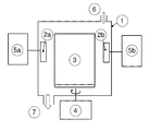
Before deposition, the inserts were cleaned in ultrasonic baths of an alkali solution and alcohol. The system was evacuated to a pressure of less than 2.0×10⁻³ Pa, after which the body were sputter cleaned with Ar ions. At first, a bonding layer of TiN with a thickness of 0.2 μm followed by a textured (Al,Cr)2O3 layer of thickness 2.5 μm, were grown by cathodic arc evaporation of an alloyed (40 at % Al+60 at % Cr) cathode, 63 mm in diameter (position (2 a) and (2 b) in FIG. 2A ) in 99.995% pure O2 atmosphere at a total pressure of 5.5 Pa and a deposition temperature of about 650° C. to a total coating thickness of 3 μm. The evaporation current was 75 A and the bias was held at −75 V during depositions. Finally, a top coating consisting of 0.3 μm (Al,Cr)N and 0.2 μm TiN was applied.
A fractured cross-section SEM micrograph of the coating is shown in FIG. 3 with (A) body, (B) bonding layer, (C) (Al,Cr)O layer, (D) (Al,Cr)N layer and (E) TiN layer.
The XRD patterns of the as-deposited layers were obtained using CuKα-radiation and a θ-2θ configuration. FIG. 4 shows the XRD pattern of a coating according to the invention with a textured corundum phase alumina (Al,Cr)2O3 layer. The peaks originating from the (Al,Cr)2O3 layer are marked with dashed lines whereas the peaks of cemented carbide are marked with solid lines.
The EBSD pole figure (FIG. 5A ) and pole plot graph (FIG. 5B ) of the as-deposited corundum phase (Al,Cr)2O3 layers in the c-axis (001) direction (FIG. 1A ), respectively, showing a fiber texture (rotational symmetry) in the direction of the coated surface normal (FIG. 1B ) with an inclination angle, φ (FIG. 1B ), of the basal planes relative to the coated surface normal between 0 and 20°. The highest peak in the pole plot is close to 0°. The EBSD data were obtained using a LEO Ultra 55 scanning electron microscope operated at 20 kV equipped with a HKL Nordlys II EBSD detector and evaluated with the Channel 5 software.
The residual stress, σ, of the (Al,Cr)2O3 coating was evaluated by XRD measurements using the sin2ψ method. The measurements were performed using CrKα-radiation on the (Al,Cr)2O3 (116)-reflection. The residual stress value was 2.1±0.2 GPa as evaluated using a Poisson's ratio of ν=0.26 and Young's modulus of E=420 GPa.
The composition, y=0.49, of (Al1-yCry)2O3 was estimated by energy dispersive spectroscopy (EDS) analysis using a LEO Ultra 55 scanning electron microscope with a Thermo Noran EDS detector operating at 10 kV. The data were evaluated using a Noran System Six (NSS ver 2) software.
Grade B: A layer of 3.0 μm Ti0.34Al0.66N was deposited by PVD on cemented carbide inserts with the composition 10.3 wt % Co and balance WC, according to prior art.
Grade C: A coating consisting of 3.0 μm Ti(C,N)+3 μm α-Al2O3 was deposited by CVD on cemented carbide inserts with the composition 10.3 wt % Co and balance WC, according to prior art.
Grade D: Example 1 was repeated using cemented carbide inserts with the composition 5.3 wt % Co and balance WC.
Grade E: A layer of 3.0 μm Ti0.34Al0.66N was deposited by PVD on cemented carbide inserts with the composition 5.3 wt % Co and balance WC, according to prior art.
Grade F: A coating consisting of 3.0 μm Ti(C,N)+3 μm α-Al2O3 was deposited by CVD on cemented carbide inserts with the composition 5.3 wt % Co and balance WC, according to prior art.
Grades A, B and C were tested in machining in steel.
| Operation | Face milling | ||
| Cutter diameter | 125 mm | ||
| Material | SS1672 | ||
| Insert type | SEEX1204AFTN-M15 | ||
| Cutting speed | 300 m/min | ||
| Feed | 0.2 mm/tooth | ||
| Depth of cut | 2,5 mm | ||
| Width of cut | 120 mm | ||
| Results | Tool life (min) | ||
| Grade A | 7.4 | ||
| (grade according to invention) | |||
| Grade B | 6.2 | ||
| Grade C | 3.3 | ||
The test was stopped at the same maximum flank wear. The wear resistance was much improved with the grade according to the invention.
Grades A, B and C were tested in machining in stainless steel.
| Operation | Shoulder milling | ||
| Cutter diameter | 32 mm | ||
| Material | SS1672 | ||
| Insert type | XOEX120408-M07 | ||
| Cutting speed | 275 m/min | ||
| Feed | 0.25 mm/tooth | ||
| Depth of | 3 mm | ||
| Width of cut | 8.8 mm | ||
| Results | Tool life (min) | ||
| Grade A | 6.2 | ||
| (grade according to invention) | |||
| Grade B | 4.1 | ||
| Grade C | failed | ||
The test was stopped at the same maximum flank wear. The wear resistance was much improved with the grade according to the invention.
Grades D, E and F were tested in machining in stainless steel.
| Operation | Interrupted turning | ||
| Material | SS2348 | ||
| Insert type | CNMG120408-MR3 | ||
| Cutting speed | 80 m/min | ||
| Feed | 0.3 mm | ||
| Depth of cut | 2 mm | ||
| Results | Tool life (cycles) | ||
| Grade D | 7 | ||
| (grade according to invention) | |||
| Grade E | 2 | ||
| Grade F | 5 | ||
The test was stopped at the same maximum flank wear. The wear resistance was much improved with the grade according to the invention.
Grades D, E and F were tested in machining in stainless steel.
| Operation | Interrupted turning | ||
| Material | SS1672 | ||
| Insert type | CNMG120408-MR3 | ||
| Cutting speed | 350 m/min | ||
| Feed | 0.3 mm | ||
| Depth of cut | 2 mm | ||
| Results | Tool life (min) | ||
| Grade D | 11.1 | ||
| (grade according to invention) | |||
| Grade E | 4.5 | ||
| Grade F | 9.2 | ||
The test was stopped at the same maximum flank wear. The wear resistance was much improved with the grade according to the invention.
When ranges are used herein for physical properties, such as molecular weight, or chemical properties, such as chemical formulae, all combinations and subcombinations of ranges specific embodiments therein are intended to be included.
The disclosures of each patent, patent application, and publication cited or described in this document are hereby incorporated herein by reference, in their entirety.
Those skilled in the art will appreciate that numerous changes and modifications can be made to the preferred embodiments of the invention and that such changes and modifications can be made without departing from the spirit of the invention. It is, therefore, intended that the appended claims cover all such equivalent variations as fall within the true spirit and scope of the invention.
Claims (4)
1. A method of making a cutting tool insert comprising:
a body comprising a hard alloy selected from the group consisting of cemented carbide, cermet, ceramics, cubic boron nitride based material, and high speed steel; and
a hard and wear resistant coating applied on said body;
wherein said coating comprises at least one (Al,Cr)2O3 layer;
wherein said (Al,Cr)2O3 layer has a corundum phase crystalline structure and a structure and a composition (Al1-yCry)2O3 with about 0.5≦y≦about 0.7 with a thickness of about 0.5 μm to about 10 μm and a fiber texture, rotational symmetry, in the direction of the coated surface normal with an inclination angle, φ, of the basal planes relative to the coated surface normal is about 0°<φ<about 20° or the inclination angle, φ, for the highest peak in the pole plot is about 0°<φ<about 20°
said method comprising the step of:
depositing on said body said (Al,Cr)2O3 layer by cathodic arc evaporation using Al+Cr-cathodes with a composition of about (20 at % Al+80 at % Cr) and about (60 at % Al+40 at % Cr), an evaporation current between about 50 A and about 200 A depending on the cathode size in an atmosphere comprising a gas selected from the group consisting of Ar, O2, and combinations thereof, at a total pressure of about 2.0 Pa to about 7.0 Pa, a bias of about −50 V to about −200 V, and a deposition temperature of about 500° C. and about 700° C.
2. The method according to claim 1 ,
depositing said (Al,Cr)2O3 layer by cathodic arc evaporation using Al+Cr-cathodes with a composition of about (30 at % Al+70 at % Cr) and about (50 at % Al+50 at % Cr), an evaporation current between about 60 A and about 90 A depending on the cathode size in an atmosphere that is O2 at a total pressure of about 4.0 Pa to about 7.0 Pa, a bias of about −50 V to about −100 V and a deposition temperature of about 600° C. and about 700° C.
3. A method for machining of steel or stainless steel, comprising:
machining with a cutting tool insert according to claim 1 at a cutting speed of about 75-600 m/min, with an average feed, per tooth in the case of milling, of about 0.08-0.5 mm.
4. A method for machining of steel or stainless steel, comprising:
machining with a cutting tool insert according to claim 1 at a cutting speed of about 150-500 m/min, with an average feed, per tooth in the case of milling, of about 0.1-0.4 mm.
Priority Applications (1)
| Application Number | Priority Date | Filing Date | Title |
|---|---|---|---|
| US13/165,289 US8043482B1 (en) | 2008-03-07 | 2011-06-21 | Oxide coated cutting insert |
Applications Claiming Priority (5)
| Application Number | Priority Date | Filing Date | Title |
|---|---|---|---|
| SE0800541 | 2008-03-07 | ||
| SE0800541-5 | 2008-03-07 | ||
| SE0800541A SE532048C2 (en) | 2008-03-07 | 2008-03-07 | Oxide coated cutting tool cutter for chip separating machining of steel |
| US12/399,466 US7989060B2 (en) | 2008-03-07 | 2009-03-06 | Oxide coated cutting insert |
| US13/165,289 US8043482B1 (en) | 2008-03-07 | 2011-06-21 | Oxide coated cutting insert |
Related Parent Applications (1)
| Application Number | Title | Priority Date | Filing Date |
|---|---|---|---|
| US12/399,466 Division US7989060B2 (en) | 2008-03-07 | 2009-03-06 | Oxide coated cutting insert |
Publications (2)
| Publication Number | Publication Date |
|---|---|
| US20110250362A1 US20110250362A1 (en) | 2011-10-13 |
| US8043482B1 true US8043482B1 (en) | 2011-10-25 |
Family
ID=41053915
Family Applications (2)
| Application Number | Title | Priority Date | Filing Date |
|---|---|---|---|
| US12/399,466 Expired - Fee Related US7989060B2 (en) | 2008-03-07 | 2009-03-06 | Oxide coated cutting insert |
| US13/165,289 Expired - Fee Related US8043482B1 (en) | 2008-03-07 | 2011-06-21 | Oxide coated cutting insert |
Family Applications Before (1)
| Application Number | Title | Priority Date | Filing Date |
|---|---|---|---|
| US12/399,466 Expired - Fee Related US7989060B2 (en) | 2008-03-07 | 2009-03-06 | Oxide coated cutting insert |
Country Status (4)
| Country | Link |
|---|---|
| US (2) | US7989060B2 (en) |
| EP (1) | EP2141257B1 (en) |
| CN (1) | CN101524905B (en) |
| SE (1) | SE532048C2 (en) |
Families Citing this family (13)
| Publication number | Priority date | Publication date | Assignee | Title |
|---|---|---|---|---|
| SE532049C2 (en) * | 2008-03-07 | 2009-10-13 | Seco Tools Ab | Oxide coated cutting tool cutter for chip separating machining of steel |
| SE532047C2 (en) * | 2008-03-07 | 2009-10-13 | Seco Tools Ab | Oxide coated cutting tool cutter for chip separating machining of cast iron |
| SE532050C2 (en) * | 2008-03-07 | 2009-10-13 | Seco Tools Ab | Oxide coated cutting tool cutter for chip separating machining of steel |
| JP6608937B2 (en) * | 2015-08-29 | 2019-11-20 | 京セラ株式会社 | Coated tool |
| JP6578935B2 (en) * | 2015-12-24 | 2019-09-25 | 三菱マテリアル株式会社 | Surface coated cutting tool with excellent chipping and wear resistance with excellent hard coating layer |
| EP3406761A1 (en) * | 2017-05-24 | 2018-11-28 | Walter Ag | A method for producing a coated cutting tool and a coated cutting tool |
| JP6910598B2 (en) * | 2017-12-26 | 2021-07-28 | 株式会社Moldino | Cover cutting tool |
| WO2020166683A1 (en) * | 2019-02-14 | 2020-08-20 | 三菱マテリアル株式会社 | Surface-coated cutting tool |
| JP7453613B2 (en) | 2019-02-14 | 2024-03-21 | 三菱マテリアル株式会社 | surface coated cutting tools |
| CN111658511B (en) * | 2020-06-02 | 2022-05-06 | 西安交通大学 | Hollow loop type electric heating needle with adjustable heating position |
| CN112281115B (en) * | 2020-10-30 | 2023-04-07 | 贵州大学 | Crystalline cubic aluminum chromium trioxide stable structure coating obtained at low temperature and preparation method thereof |
| CN114686883B (en) * | 2022-04-07 | 2023-04-28 | 赣州澳克泰工具技术有限公司 | Cutting tool with gradient multilayer coating and preparation method thereof |
| CN115074731A (en) * | 2022-05-10 | 2022-09-20 | 四川大学 | Porous composite TiCN/TiAlXN wear-resistant and oxidation-resistant coating and preparation method and application thereof |
Citations (21)
| Publication number | Priority date | Publication date | Assignee | Title |
|---|---|---|---|---|
| US5310607A (en) | 1991-05-16 | 1994-05-10 | Balzers Aktiengesellschaft | Hard coating; a workpiece coated by such hard coating and a method of coating such workpiece by such hard coating |
| JPH06322517A (en) | 1993-03-15 | 1994-11-22 | Takeshi Masumoto | Wear resistant amorphous hard film and its production |
| EP0659153A1 (en) | 1992-09-03 | 1995-06-28 | CLARKSON, Melvin | Suspended beverage infusion bag |
| EP0659903A1 (en) | 1993-12-23 | 1995-06-28 | Sandvik Aktiebolag | Alumina coated cutting tool |
| EP0738336A1 (en) | 1994-01-14 | 1996-10-23 | Sandvik Aktiebolag | Oxide coated cutting tool |
| EP0603144B1 (en) | 1992-12-18 | 1996-11-20 | Sandvik Aktiebolag | Oxide coated cutting tool |
| EP0744473A1 (en) | 1995-05-22 | 1996-11-27 | Fraunhofer-Gesellschaft Zur Förderung Der Angewandten Forschung E.V. | Vacuum coated composite body and method of its production |
| JP2002053946A (en) | 2000-08-04 | 2002-02-19 | Kobe Steel Ltd | Hard film and wear resistant member, and manufacturing method thereof |
| US6767627B2 (en) | 2002-12-18 | 2004-07-27 | Kobe Steel, Ltd. | Hard film, wear-resistant object and method of manufacturing wear-resistant object |
| US20040202877A1 (en) | 2001-02-16 | 2004-10-14 | Sandvik Aktiebolag | Alpha-alumina coated cutting tool |
| EP1477581A1 (en) | 2003-05-10 | 2004-11-17 | Seco Tools Ab | Enhanced alumina layer produced by CVD |
| EP1479791A2 (en) | 2003-02-28 | 2004-11-24 | Mitsubishi Materials Corporation | Cutting tool |
| EP1528125A2 (en) | 2003-10-27 | 2005-05-04 | Seco Tools Ab | Coated cutting insert for rough turning |
| EP1655388A2 (en) | 2004-11-05 | 2006-05-10 | Seco Tools Ab | Alumina layer with controlled texture |
| EP1655392A1 (en) | 2004-11-05 | 2006-05-10 | Seco Tools Ab | Alumina layer with enhanced texture |
| EP1655387A1 (en) | 2004-11-05 | 2006-05-10 | Seco Tools Ab | Enhanced alumina layer with texture |
| US20060263640A1 (en) | 2003-04-30 | 2006-11-23 | Kabushiki Kaisha Krobe Seiko Sho(Kobe Steel Ltd) | Alumina protective coating film and method for formation thereof |
| US20070104945A1 (en) | 2005-09-27 | 2007-05-10 | Seco Tools Ab | Alumina layer with enhanced texture |
| US7273665B2 (en) | 2003-12-22 | 2007-09-25 | Mitsubishi Materials Corporation | Surface-coated cermet cutting tool with hard coating layer having excellent chipping resistance |
| US7276301B2 (en) | 2003-11-25 | 2007-10-02 | Mitsubishi Materials Corporation | Surface-coated cermet cutting tool with a hard coating layer exhibiting excellent chipping resistance |
| US20080090099A1 (en) | 2006-10-11 | 2008-04-17 | Oc Oerlikon Balzers Ag | Layer system with at least one mixed crystal layer of a multi-oxide |
Family Cites Families (6)
| Publication number | Priority date | Publication date | Assignee | Title |
|---|---|---|---|---|
| EP1553210B1 (en) * | 2002-08-08 | 2014-05-28 | Kabushiki Kaisha Kobe Seiko Sho | PROCESS FOR PRODUCING ALUMINA COATING COMPOSED MAINLY OF a-TYPE CRYSTAL STRUCTURE |
| RU2320775C2 (en) * | 2002-09-24 | 2008-03-27 | Исикавадзима-Харима Хэви Индастриз Ко., Лтд. | Method for depositing of coating onto sliding surface of fire-resistant member, fire-resistant member, and electrode for electric discharge treatment of surface |
| JP4389152B2 (en) * | 2003-07-10 | 2009-12-24 | 三菱マテリアル株式会社 | Surface-coated cemented carbide cutting tool that exhibits excellent chipping resistance under heavy cutting conditions. |
| SE532050C2 (en) * | 2008-03-07 | 2009-10-13 | Seco Tools Ab | Oxide coated cutting tool cutter for chip separating machining of steel |
| SE532049C2 (en) * | 2008-03-07 | 2009-10-13 | Seco Tools Ab | Oxide coated cutting tool cutter for chip separating machining of steel |
| SE532047C2 (en) * | 2008-03-07 | 2009-10-13 | Seco Tools Ab | Oxide coated cutting tool cutter for chip separating machining of cast iron |
-
2008
- 2008-03-07 SE SE0800541A patent/SE532048C2/en not_active IP Right Cessation
-
2009
- 2009-03-03 EP EP09003007.3A patent/EP2141257B1/en not_active Not-in-force
- 2009-03-06 US US12/399,466 patent/US7989060B2/en not_active Expired - Fee Related
- 2009-03-09 CN CN2009101346970A patent/CN101524905B/en not_active Expired - Fee Related
-
2011
- 2011-06-21 US US13/165,289 patent/US8043482B1/en not_active Expired - Fee Related
Patent Citations (22)
| Publication number | Priority date | Publication date | Assignee | Title |
|---|---|---|---|---|
| US5310607A (en) | 1991-05-16 | 1994-05-10 | Balzers Aktiengesellschaft | Hard coating; a workpiece coated by such hard coating and a method of coating such workpiece by such hard coating |
| US5447804A (en) | 1991-05-16 | 1995-09-05 | Balzers Aktiengesellschaft | Hard coating; a workpiece coated by such hard coating and a method of coating such workpiece by such hard coating |
| EP0659153A1 (en) | 1992-09-03 | 1995-06-28 | CLARKSON, Melvin | Suspended beverage infusion bag |
| EP0603144B1 (en) | 1992-12-18 | 1996-11-20 | Sandvik Aktiebolag | Oxide coated cutting tool |
| JPH06322517A (en) | 1993-03-15 | 1994-11-22 | Takeshi Masumoto | Wear resistant amorphous hard film and its production |
| EP0659903A1 (en) | 1993-12-23 | 1995-06-28 | Sandvik Aktiebolag | Alumina coated cutting tool |
| EP0738336A1 (en) | 1994-01-14 | 1996-10-23 | Sandvik Aktiebolag | Oxide coated cutting tool |
| EP0744473A1 (en) | 1995-05-22 | 1996-11-27 | Fraunhofer-Gesellschaft Zur Förderung Der Angewandten Forschung E.V. | Vacuum coated composite body and method of its production |
| JP2002053946A (en) | 2000-08-04 | 2002-02-19 | Kobe Steel Ltd | Hard film and wear resistant member, and manufacturing method thereof |
| US20040202877A1 (en) | 2001-02-16 | 2004-10-14 | Sandvik Aktiebolag | Alpha-alumina coated cutting tool |
| US6767627B2 (en) | 2002-12-18 | 2004-07-27 | Kobe Steel, Ltd. | Hard film, wear-resistant object and method of manufacturing wear-resistant object |
| EP1479791A2 (en) | 2003-02-28 | 2004-11-24 | Mitsubishi Materials Corporation | Cutting tool |
| US20060263640A1 (en) | 2003-04-30 | 2006-11-23 | Kabushiki Kaisha Krobe Seiko Sho(Kobe Steel Ltd) | Alumina protective coating film and method for formation thereof |
| EP1477581A1 (en) | 2003-05-10 | 2004-11-17 | Seco Tools Ab | Enhanced alumina layer produced by CVD |
| EP1528125A2 (en) | 2003-10-27 | 2005-05-04 | Seco Tools Ab | Coated cutting insert for rough turning |
| US7276301B2 (en) | 2003-11-25 | 2007-10-02 | Mitsubishi Materials Corporation | Surface-coated cermet cutting tool with a hard coating layer exhibiting excellent chipping resistance |
| US7273665B2 (en) | 2003-12-22 | 2007-09-25 | Mitsubishi Materials Corporation | Surface-coated cermet cutting tool with hard coating layer having excellent chipping resistance |
| EP1655388A2 (en) | 2004-11-05 | 2006-05-10 | Seco Tools Ab | Alumina layer with controlled texture |
| EP1655392A1 (en) | 2004-11-05 | 2006-05-10 | Seco Tools Ab | Alumina layer with enhanced texture |
| EP1655387A1 (en) | 2004-11-05 | 2006-05-10 | Seco Tools Ab | Enhanced alumina layer with texture |
| US20070104945A1 (en) | 2005-09-27 | 2007-05-10 | Seco Tools Ab | Alumina layer with enhanced texture |
| US20080090099A1 (en) | 2006-10-11 | 2008-04-17 | Oc Oerlikon Balzers Ag | Layer system with at least one mixed crystal layer of a multi-oxide |
Non-Patent Citations (4)
| Title |
|---|
| Ramm et al "Pulse enhanced electron emission (P3eTM) arc evaporation and the synthesis of wear resistant AI-Cr-O coatings in corundum structure" Suface & Coatings Technology 202 (2007) p. 876-883. |
| Ramm et al "Thermal stability of thin film corundum-type solid solutions of (AI(1-x)Cr(x))2(0)3 synthesized under low temperature non-equilibrium" Advanced Engeering Materials 2007,9, No. 7 p. 604-608. |
| Viktorov et al "Fine structure of alpha-AI203-based solid solutions" Inorganic Materials, vol. 37, No. 10, 2001 p. 983-991. |
| Witthaut et al "Preparation of Cr203-A1203 solid solutions by reactive magnetron sputtering" Mikrochim Acta 133, 2000 p. 191-196. |
Also Published As
| Publication number | Publication date |
|---|---|
| EP2141257B1 (en) | 2014-08-27 |
| SE0800541L (en) | 2009-09-08 |
| US20090226716A1 (en) | 2009-09-10 |
| CN101524905A (en) | 2009-09-09 |
| EP2141257A2 (en) | 2010-01-06 |
| US7989060B2 (en) | 2011-08-02 |
| EP2141257A3 (en) | 2013-08-21 |
| SE532048C2 (en) | 2009-10-13 |
| US20110250362A1 (en) | 2011-10-13 |
| CN101524905B (en) | 2012-12-05 |
Similar Documents
| Publication | Publication Date | Title |
|---|---|---|
| US8043482B1 (en) | Oxide coated cutting insert | |
| US8075743B2 (en) | Oxide coated cutting insert | |
| EP1877595B1 (en) | Cutting tool insert, solid end mill or drill coated with wear resistant layer. | |
| US6673430B2 (en) | PVD Al2O3 coated cutting tool | |
| US9180522B2 (en) | Coated cutting tool insert | |
| US8409696B2 (en) | Multilayered coated cutting tool | |
| EP1722009A1 (en) | Thin wear resistant coating | |
| EP1736565A1 (en) | Composite coatings for finishing of hardened steels | |
| KR100945702B1 (en) | Coated cutting tool insert | |
| EP1120387A1 (en) | Cutting tool made of Al203-coated cubic boron nitride-based sintered material | |
| US8409731B2 (en) | Oxide coated cutting insert | |
| US8409732B2 (en) | Oxide coated cutting insert |
Legal Events
| Date | Code | Title | Description |
|---|---|---|---|
| STCF | Information on status: patent grant |
Free format text: PATENTED CASE |
|
| FPAY | Fee payment |
Year of fee payment: 4 |
|
| FEPP | Fee payment procedure |
Free format text: MAINTENANCE FEE REMINDER MAILED (ORIGINAL EVENT CODE: REM.); ENTITY STATUS OF PATENT OWNER: LARGE ENTITY |
|
| LAPS | Lapse for failure to pay maintenance fees |
Free format text: PATENT EXPIRED FOR FAILURE TO PAY MAINTENANCE FEES (ORIGINAL EVENT CODE: EXP.); ENTITY STATUS OF PATENT OWNER: LARGE ENTITY |
|
| STCH | Information on status: patent discontinuation |
Free format text: PATENT EXPIRED DUE TO NONPAYMENT OF MAINTENANCE FEES UNDER 37 CFR 1.362 |
|
| FP | Lapsed due to failure to pay maintenance fee |
Effective date: 20191025 |