EP1478899B1 - Determiner le profil d'une surface d'un objet - Google Patents
Determiner le profil d'une surface d'un objet Download PDFInfo
- Publication number
- EP1478899B1 EP1478899B1 EP03709731A EP03709731A EP1478899B1 EP 1478899 B1 EP1478899 B1 EP 1478899B1 EP 03709731 A EP03709731 A EP 03709731A EP 03709731 A EP03709731 A EP 03709731A EP 1478899 B1 EP1478899 B1 EP 1478899B1
- Authority
- EP
- European Patent Office
- Prior art keywords
- inspection
- signal
- receiver
- transmitter
- calibration
- Prior art date
- Legal status (The legal status is an assumption and is not a legal conclusion. Google has not performed a legal analysis and makes no representation as to the accuracy of the status listed.)
- Expired - Lifetime
Links
- 238000000691 measurement method Methods 0.000 title 1
- 238000007689 inspection Methods 0.000 claims abstract description 101
- 238000000034 method Methods 0.000 claims abstract description 49
- 239000000523 sample Substances 0.000 claims abstract description 39
- 230000001052 transient effect Effects 0.000 claims abstract description 21
- 230000004044 response Effects 0.000 claims abstract description 11
- 230000007797 corrosion Effects 0.000 claims description 74
- 238000005260 corrosion Methods 0.000 claims description 74
- 238000012937 correction Methods 0.000 claims description 11
- 238000005303 weighing Methods 0.000 claims description 4
- 230000035699 permeability Effects 0.000 claims description 2
- 230000001939 inductive effect Effects 0.000 abstract description 4
- 238000005259 measurement Methods 0.000 description 29
- 229910000831 Steel Inorganic materials 0.000 description 15
- 239000010959 steel Substances 0.000 description 15
- 230000007547 defect Effects 0.000 description 13
- 230000000694 effects Effects 0.000 description 5
- 230000007423 decrease Effects 0.000 description 4
- 238000012360 testing method Methods 0.000 description 4
- 230000008901 benefit Effects 0.000 description 3
- 238000011088 calibration curve Methods 0.000 description 3
- 239000004020 conductor Substances 0.000 description 3
- 238000009413 insulation Methods 0.000 description 3
- 230000005355 Hall effect Effects 0.000 description 2
- 238000005422 blasting Methods 0.000 description 2
- 230000008859 change Effects 0.000 description 2
- 230000005284 excitation Effects 0.000 description 2
- 238000002474 experimental method Methods 0.000 description 2
- 230000010354 integration Effects 0.000 description 2
- 239000012811 non-conductive material Substances 0.000 description 2
- 239000003973 paint Substances 0.000 description 2
- 125000006850 spacer group Chemical group 0.000 description 2
- 229910000975 Carbon steel Inorganic materials 0.000 description 1
- 238000013459 approach Methods 0.000 description 1
- 239000010962 carbon steel Substances 0.000 description 1
- 238000007796 conventional method Methods 0.000 description 1
- 230000003247 decreasing effect Effects 0.000 description 1
- 230000001419 dependent effect Effects 0.000 description 1
- 230000005672 electromagnetic field Effects 0.000 description 1
- 238000011156 evaluation Methods 0.000 description 1
- 231100001261 hazardous Toxicity 0.000 description 1
- 238000009434 installation Methods 0.000 description 1
- 238000013507 mapping Methods 0.000 description 1
- 239000000463 material Substances 0.000 description 1
- 239000011159 matrix material Substances 0.000 description 1
- 239000002184 metal Substances 0.000 description 1
- 239000000203 mixture Substances 0.000 description 1
- 238000012986 modification Methods 0.000 description 1
- 230000004048 modification Effects 0.000 description 1
- 230000008439 repair process Effects 0.000 description 1
- 239000007787 solid Substances 0.000 description 1
- GOLXNESZZPUPJE-UHFFFAOYSA-N spiromesifen Chemical compound CC1=CC(C)=CC(C)=C1C(C(O1)=O)=C(OC(=O)CC(C)(C)C)C11CCCC1 GOLXNESZZPUPJE-UHFFFAOYSA-N 0.000 description 1
- 239000010935 stainless steel Substances 0.000 description 1
- 229910001220 stainless steel Inorganic materials 0.000 description 1
- 239000000126 substance Substances 0.000 description 1
- 230000003746 surface roughness Effects 0.000 description 1
Images


Classifications
-
- G—PHYSICS
- G01—MEASURING; TESTING
- G01N—INVESTIGATING OR ANALYSING MATERIALS BY DETERMINING THEIR CHEMICAL OR PHYSICAL PROPERTIES
- G01N27/00—Investigating or analysing materials by the use of electric, electrochemical, or magnetic means
- G01N27/72—Investigating or analysing materials by the use of electric, electrochemical, or magnetic means by investigating magnetic variables
- G01N27/82—Investigating or analysing materials by the use of electric, electrochemical, or magnetic means by investigating magnetic variables for investigating the presence of flaws
- G01N27/90—Investigating or analysing materials by the use of electric, electrochemical, or magnetic means by investigating magnetic variables for investigating the presence of flaws using eddy currents
- G01N27/9073—Recording measured data
- G01N27/9086—Calibrating of recording device
-
- G—PHYSICS
- G01—MEASURING; TESTING
- G01B—MEASURING LENGTH, THICKNESS OR SIMILAR LINEAR DIMENSIONS; MEASURING ANGLES; MEASURING AREAS; MEASURING IRREGULARITIES OF SURFACES OR CONTOURS
- G01B7/00—Measuring arrangements characterised by the use of electric or magnetic techniques
- G01B7/28—Measuring arrangements characterised by the use of electric or magnetic techniques for measuring contours or curvatures
- G01B7/281—Measuring arrangements characterised by the use of electric or magnetic techniques for measuring contours or curvatures for measuring contour or curvature along an axis, e.g. axial curvature of a pipeline or along a series of feeder rollers
-
- G—PHYSICS
- G01—MEASURING; TESTING
- G01N—INVESTIGATING OR ANALYSING MATERIALS BY DETERMINING THEIR CHEMICAL OR PHYSICAL PROPERTIES
- G01N27/00—Investigating or analysing materials by the use of electric, electrochemical, or magnetic means
- G01N27/72—Investigating or analysing materials by the use of electric, electrochemical, or magnetic means by investigating magnetic variables
- G01N27/82—Investigating or analysing materials by the use of electric, electrochemical, or magnetic means by investigating magnetic variables for investigating the presence of flaws
- G01N27/90—Investigating or analysing materials by the use of electric, electrochemical, or magnetic means by investigating magnetic variables for investigating the presence of flaws using eddy currents
- G01N27/9013—Arrangements for scanning
- G01N27/902—Arrangements for scanning by moving the sensors
Definitions
- the present invention relates to a method of determining a surface profile of an electrically conductive object.
- a probe is used, which comprises a transmitter/receiver arrangement, wherein the transmitter is adapted to induce transient eddy currents in the object, and wherein the receiver is adapted to provide a signal indicative of the strength of a magnetic field or changes in the strength of a magnetic field.
- Transient eddy currents are generally induced when the electrically conductive object is subjected to a non-steady changing magnetic field, such as generated by a coil that is energized by a current pulse. Transient eddy currents change with time after excitation, generally decaying to zero in the absence of further excitation, and so does the signal received in the receiver.
- Transient eddy-current methods are useful inspection techniques, and examples of objects that can suitably be inspected with the method according to the present invention are metal plates or walls of container means, such as pipes, vessels or containers, having a radius of curvature that is larger than the thickness of the object.
- the electrically conducting material can be any electrically conducting material, for example carbon steel or stainless steel.
- surface profile is used in the claims and in the description to refer to a representation of the shortest distance to a surface from known reference points, which are for example arranged along a line or in a plane substantially parallel to the surface to be inspected.
- a surface profile can reveal surface roughness, and anomalies such as a local decrease of the thickness of the object, which decrease is caused for example by corrosion.
- a particularly important parameter which can be derived from a surface profile is the depth of an anomaly.
- the depth of a corrosion spot is a critical parameter for the integrity assessment, since it is related to the remaining wall thickness.
- European patent specification No. 321 112 discloses a method of determining the thickness of a container wall means under insulation.
- a probe comprising a transmitter coil for inducing eddy currents in the object, and a receiver system for providing a signal indicative of changes in the strength of a magnetic field.
- the known method comprises inducing transient eddy currents in the object; receiving a signal indicative of the eddy current, and comparing the decay of the received signal over a period of time with a reference decay indicative of a known wall thickness, whereby the thickness of the container means wall portion can be inferred.
- the method of determining a surface profile of an electrically conductive object, using a probe comprising a transmitter which is adapted to induce transient eddy currents in the object, and a receiver which is adapted to provide a signal indicative of the strength of a magnetic field or changes in the strength of a magnetic field, the transmitter and receiver forming a transmitter/receiver arrangement, according to the present invention comprises the steps of:
- the invention is based on the insight gained by Applicant, that the overall amplitude of a signal received by a probe in response to transient eddy currents in an object, can be used to quantify the distance between the probe and the object. By performing measurements systematically at a number of selected inspection positions, a surface profile can thus be obtained.
- the transmitter/receiver arrangement can comprise a further (second) receiver, spaced apart from the first receiver, and the calibration values and the inspection values are in this case determined from the signals generated in the first and second receivers at the respective position of the transmitter/receiver arrangement.
- a transmitter/receiver arrangement is particularly useful when it is oriented such that the first and second receivers are spaced substantially along the normal to the surface at the point to be investigated, and when the calibration values and inspection values relate to a ratio of characteristic values of the signals generated in the first and second receivers.
- the inspection values can be interpreted so as to determine a parameter that is a measure of an electromagnetic property of the object at the inspection point.
- the method of the present invention can be used to determine a correction for conventional wall thickness measurements, wherein a wall thickness has been determined from a characteristic of the signal at any one of the inspection positions corresponding to the inspection point, wherein in the correction the determined parameter that is a measure of an electromagnetic property of the object at the inspection point is taken into account.
- the electrically conductive object is covered with corrosion products at one or more inspection points, and one is interested in the true surface profile of the object underneath the corrosion products.
- the present invention also provides a method for determining a the surface profile underneath corrosion products, wherein the method further comprises obtaining a signal representing the response generated by isolated corrosion products in the receiver to pulsed energizing of the transmitter; and applying a correction to account for the signal contribution from corrosion products to the total signal received at an inspection position corresponding to the corroded inspection point.
- the correction suitably comprises comparing the total signal and the signal representing isolated corrosion products at a time or in a time interval where the signal contribution from corrosion products dominates the total signal.
- a corrected signal pertaining to the corroded inspection point can be obtained, in which corrected signal the contribution of corrosion products has been eliminated, so that the inspection value pertaining to the corroded inspection point can be determined by determining the characteristic value of the corrected signal.
- a conformable sensor coil array is described, which can be used for pipeline inspection.
- the operation of the array is not based on exciting transient eddy currents and following the accompanying signal over time as in the present invention. Rather, the sensor coils are activated by an alternating current of a selected frequency, for an extended period of time, thereby generating steady-state eddy currents in the inspected object.
- By analysing the complex impedance of the coils prefabricated defects in a steel test object could be detected. The influence of corrosion products on the measurements is not discussed.
- the object of electrically conducting material is referred to with reference numeral 2 and the probe is referred to with reference numeral 4.
- the probe 4 comprises a transmitter/receiver arrangement having a transmitter coil 6 for transmitting an electromagnetic field and a receiver coil 8.
- the transmitter coil 6 is connected to a device (not shown) for energizing the transmitter coil and the receiver is connected to a device (not shown) for recording the signals from the receiver.
- the distance between a selected point in the probe 4 and the surface 12 of the object 2 is denoted by L, and part of the space between the probe 4 and the object 2 is for example filled with paint, or with an insulation layer (not shown) covering the surface 12.
- the surface 12 is the surface of the object nearest to the probe.
- the object 2 has an anomaly at the surface 12, which anomaly is being referred to with reference numeral 15.
- a calibration is performed. To this end a calibration point 20 is selected on the surface 12, suitably in an area of the surface without anomalies.
- a set of calibration positions of the probe 4 including the transmitter/receiver arrangement are selected relative to the calibration point 20, suitably at different distances L along the normal of the surface.
- Three calibration positions 22a, 22b, and 22c are indicated in the Figure, which are separated along the normal 25 through the surface at the calibration point 20.
- a suitable way to arrange the probe at the different calibration positions is for example to place plastic spacers or stacks of plastic spacers of known thickness on the surface, and to place the probe on top thereof.
- a set of calibration values corresponding to the set of calibration positions is determined.
- the probe 4 is placed at one of the calibration positions, for example at position 22b, having a distance L b from the surface 12.
- Eddy currents are induced in the object by energizing the transmitter coil 6 with a current I during a finite time interval.
- time interval is chosen so long, that eddy currents generated due to the switch-on of the current I have died out.
- eddy currents are generated again in the object 2, and cause a changing magnetic field at the location of the receiver coil 8, thereby inducing a voltage V in the receiver coil.
- Figure 2 shows schematically signals 52a, 52b, 52c which can be obtained when the voltage V, measured at the receiver coil 8 is registered as a function of time t after the current I has been switched off, when the probe 4 is in the calibration positions 22a (distance L a ), 22b (distance L b ), and 22c (distance L c ), respectively.
- the Figure illustrates, in a double logarithmic representation, that the overall amplitude of the signal increases with decreasing distance between the receiver coil 8 in the probe 4 and the surface 12, i.e. that for a selected time the signal is the stronger, the closer the receiver coil is located to the surface.
- the signals shown in Figure 2 exhibit a decay rate that is slower in the initial part of the curve, and faster for times greater than a critical time t c .
- the critical time t c reflects the time it takes for the eddy currents diffuse from one surface of the wall to the other, and is therefore a measure for the thickness of the object 2.
- a characteristic value can be determined, which is related to the amplitude of the signal.
- the voltage V(t 1 ) at a selected time t 1 can be registered, preferably in the initial part of the signal where the signal is strongest.
- Figure 3 shows a plot of the characteristic values ⁇ a , ⁇ b , ⁇ c determined for the calibration positions 22a, 22b, 22c of Figure 2, in dependence of the corresponding distances from the surface. It shall be clear that more calibration values at other calibration positions can be obtained.
- the solid curve shown in Figure 3 is a representation of the calibration function, which relates the characteristic value to the relative location of calibration point and calibration position.
- Figure 1 shows only four inspection points 30a, 30b, 30c, and 30d in a linear arrangement on the surface 12. It shall be clear, that in practice more points and other arrangements such as matrix arrangement can be selected.
- a number of inspection positions of the transmitter/receiver arrangement are selected.
- FIG 1 there are indicated four positions 32a, 32b, 32c, 32d of the probe 4 including the transmitter/receiver arrangement, which positions are arranged along a line, the normal projection of which onto the surface 12 substantially coincides with the path connecting the inspection points.
- an inspection value is determined.
- energizing of the transmitter, receiving of the signal and calculation of the inspection value from a characteristic value of the received signal is done in the same way as for determining the calibration values.
- the inspection value also relates to the amplitude of the respective signal.
- the distance, calculated from a selected point in the probe, above the respective inspection point can be determined. This can for example be done by linear interpolation. Since the location and orientation of the transmitter/receiver arrangement at the corresponding inspection position in space are known, deriving the distance corresponds to deriving the relative location of inspection point and the corresponding inspection position.
- Figure 4 shows the resulting surface profile, wherein on the abscissa the inspection points are indicated, and on the ordinate the determined distance between corresponding inspection points and inspection positions.
- the known relative position of the inspection positions with respect to each other is taken into account.
- the calibration function can suitably be represented by an analytical function, in order to facilitate evaluation with a computer.
- the analytical function can in particular be determined on the basis of a theoretical approach, this has the advantage that fewer calibration values have to be determined.
- R and ⁇ can for example be determined by a least-squares fitting of equation 2 to a limited number of calibration values, together with the known distances between calibration positions and the calibration point. Equation (2) can be inverted such that the distance z can be determined in dependence of an inspection value measured at an inspection position.
- the transmitter/receiver arrangement is formed by a single transmitter coil and a single receiver coil, stacked parallel to each other. Different transmitter/receiver arrangements can also be used.
- the receiver coil can be oriented perpendicular to the transmitter coil, and they can be laterally spaced with respect to the surface of the object to be investigated. It is also possible to use a single coil serving initially as transmitter of a magnetic pulse, and then as a receiver of the magnetic field generated by the eddy currents.
- a particularly useful transmitter/receiver arrangement comprises two spaced apart receivers.
- Figure 1 indicates at reference numeral 38 a second receiver coil, which is arranged parallel and co-axially to the first receiver coil 8.
- the total signal generated in the receiver in this case comprises the signal generated in the first receiver coil 8 and the signal generated in the second receiver coil 38.
- the receiver coils are suitably spaced apart by a distance in the order of the diameter of the receiver coils.
- the gradient of the property of the magnetic field can be determined from the gradient in the signals received in the two receivers.
- the distance of the receiver coil that is closer to the surface from the surface is selected to be approximately in the order of the diameter of the receiver coils.
- the ratio of first and second characteristic values ⁇ ' and ⁇ " of the signals generated in the first and second receiver, respectively, is evaluated.
- ⁇ ' ⁇ " V'(t 1 ) V"(t 1 )
- V'(t 1 ) and V"(t 1 ) are the voltages measured at time t 1 at the first and second receiver coils, respectively.
- Such a ratio of characteristic values can be used to determine the calibration values and measurement values in the method of the present invention.
- Each of the characteristic values relates to the signal amplitude of the signal generated in the first, or second, receivers. The skilled person will understand that it is not required to explicitly determine the first and second characteristic values separately. It is sufficient for the method of the present invention that they are implicitly represented in the calibration values and inspection values that are determined, for example when an electronic circuit is used that performs a division of voltages V'(t 1 ) and V"(t 1 ).
- the ratio of characteristic values represents a gradient in a property of the magnetic field, e.g. the magnetic field strength or the time-change of the magnetic field strength. It shall be clear that a gradient can also be defined in a different way, e.g. as a difference of signals divided by the distance of the receiver coils.
- a calibration function can be obtained relating the ratio of characteristic values ⁇ '/ ⁇ " to the distance from the surface, similar to the calibration function represented by Figure 3. Using this calibration function, an unknown distance between an inspection position and an inspection point can be derived.
- Equation (4) does not contain the proportionality constant ⁇ anymore. This illustrates an important advantage of the measurement using two receiver coils, namely that the measurements are far less dependent on the electromagnetic properties of the test object.
- the electromagnetic properties of an object to be tested may vary between different inspection points and the calibration point. This is a source of error in inspection methods based on transient eddy currents, which generally limits the accuracy of quantitative measurements.
- the method of the present invention wherein two spaced apart receivers are used and wherein the gradient of the magnetic field due to eddy currents is evaluated, allows to determine the surface profile with higher accuracy, wherein the influence from changing electromagnetic properties is taken into account.
- the factor R in equations (2) and (4) may vary somewhat with the electromagnetic properties and the geometry of the test specimen. This effect can further be taken into account when one or more further receiver coils are arranged, spaced apart from the first and second receiver coils. By combining pairs of characteristic values determined by using the individual receiver coils, two or more independent equations analogous to equation (4) can be obtained, from which both R and z can be solved.
- the method of the present invention can be used to determine a parameter that relates to an electromagnetic property of the object at the point of the surface that is being inspected. It has been discussed with reference to Figure 2 how the parameter ⁇ can be determined from measurements at different calibration positions of the transmitter/receiver arrangement corresponding to a calibration point. Similarly, on the basis of equation 2 also measurements can be evaluated wherein the transmitter coil is kept stationary, and wherein characteristic values of signals at different distances of a receiver from the point at the surface are obtained.
- the actual wall thickness or true wall thickness there are three wall thicknesses, (1) the actual wall thickness or true wall thickness, (2) the measured wall thickness (before correction) and (3) the corrected wall thickness. Correcting the measured wall thickness is done in order to get a wall thickness that is nearer to the actual wall thickness than the measured wall thickness before correction.
- the critical time of the signals that was already discussed with reference to Figure 1 is quantitatively evaluated.
- Another method includes calculating the integral of the signals in time between two predetermined times and obtaining information on the thickness from the calculated value.
- a further method is based on determining the time that it takes for the signal to decrease from a first value to a second value and obtaining the thickness from a relation between wall thickness and this time.
- All these methods are based on a calibration using measurements on an object with known wall thickness, and as such they provide a measured wall thickness WT m at the inspection point that is not corrected for the influence of different electromagnetic properties at the calibration point and at the inspection point.
- the influence from corrosion products can be taken into account.
- This aspect of the invention is particularly important when it is undesirable to remove the corrosion products, e.g. by grit-blasting.
- mechanical removal of the corrosion products can further weaken the structural integrity before the severity of corrosion has be assessed.
- a method is required that can measure the true surface profile of the electrically conductive object underneath the corrosion products.
- corrosion products of steel when subjected to a transient eddy current measurement, produce a signal in the receiver although they are non-conductive. Corrosion products are therefore a source of error in eddy current measurements of corroded objects.
- the signal from the corrosion products contributes to the total signal of the corroded object, whereas one is normally only interested in the signal from the uncorroded part of the object, in order to determine a surface profile, or a wall thickness thereof.
- Figure 5 illustrates the signal contribution from corrosion products.
- Transient eddy current signals are shown in arbitrary units as a function of time t.
- Curve a) shows the signal received from a 6.5 mm thick steel sample, wherein the probe was located 22 mm above the nearest surface of the sample.
- Curve c) shows the signal that is received from a 12 mm thick layer of corrosion products alone, when the probe is located 10 mm above the near surface of the layer. It is found that the sum of curves a) and c) corresponds well with curve b).
- the overall shape of the signal received from steel corrosion products is relatively independent of the exact chemical composition, the thickness and the shape of the corrosion products.
- Figure 5 shows, that the corrosion products contribute to the overall amplitude of the signal.
- the contribution to the total signal in curve b) is relatively smallest in the initial part, and strongest in the late time portions, beyond the critical time. From about 30 ms onwards in Figure 5, the signal from corrosion products is the dominant contribution to the total signal.
- the late time portions can therefore be used to adapt the method of the present invention so as to correct the signal for the influence from corrosion products, so that the true underlying profile of the electrically conducting (steel) surface can be obtained. This is suitably done by comparing the total signal of a corroded surface with a signal representing isolated corrosion products at a time or in a time interval where the signal contribution from corrosion products dominates the total signal.
- the contribution of corrosion products to the total signal can be determined, and a corrected signal can be determined wherein the contribution from corrosion products has been eliminated.
- a corrected signal can be determined wherein the contribution from corrosion products has been eliminated.
- the corrected signal can be calculated as a difference between the total signal, and the signal representing the response generated by isolated corrosion products multiplied with a weighing factor.
- the weighing factor can be determined by comparing of the total signal and the signal representing isolated corrosion products, at a time or in a time interval where the signal contribution from corrosion products dominates the total signal.
- the parameter X serves to correct for the influence of the corrosion products.
- the parameter is determined from a signal representing the signal obtained from isolated corrosion products.
- the signal of voltages V C (wherein the index c indicates corrosion products) is generally similar to curve c) in Figure 5.
- V C (wherein the index c indicates corrosion products) is generally similar to curve c) in Figure 5.
- the surface profile on a naturally corroded defect (anomaly) in a steel pipe was determined.
- the defect is approximately round and has a diameter at the steel surface of about 35 mm. Initially, corrosion products were removed from the defect. The defect depth was then determined with ultrasonic measurements, and was found to be 7.9 mm.
- a probe as shown in Figure 1 was used, comprising a single receiver coil.
- a calibration point was selected in a non-corroded area of the pipe, and the signal was calibration values were determined for 8 calibration positions, selected between 22 mm and 51 mm above the calibration point.
- a wooden ruler was put on the outer surface of the pipe, crossing the area of the defect from which corrosion products had been removed.
- a probe can be used, which comprises a plurality of transmitter/receiver arrangements, so that the measurement at various inspection positions (or calibration positions) can be carried out more efficiently than by moving the probe every time.
- the receivers for use with the present invention can suitably be coils.
- the property of the magnetic field that is represented in the signal from the receiver is the change of the strength of the magnetic field with time.
- the receivers can be Hall effect transducers. When the receivers are Hall effect transducers, or when the signals from the coils are integrated over time, the signals are indicative of the strength of the magnetic field.
Landscapes
- Physics & Mathematics (AREA)
- General Physics & Mathematics (AREA)
- Chemical & Material Sciences (AREA)
- Biochemistry (AREA)
- Electrochemistry (AREA)
- Health & Medical Sciences (AREA)
- Life Sciences & Earth Sciences (AREA)
- Analytical Chemistry (AREA)
- Chemical Kinetics & Catalysis (AREA)
- General Health & Medical Sciences (AREA)
- Immunology (AREA)
- Pathology (AREA)
- Investigating Or Analyzing Materials By The Use Of Magnetic Means (AREA)
- Measurement Of Length, Angles, Or The Like Using Electric Or Magnetic Means (AREA)
- Length Measuring Devices With Unspecified Measuring Means (AREA)
- Analysing Materials By The Use Of Radiation (AREA)
Claims (14)
- Procédé pour déterminer le profil d'une surface d'un objet (2) électriquement conducteur au moyen d'un détecteur (4) qui comprend un émetteur (6) qui est adapté pour induire des courants de Foucault transitoires dans l'objet et un récepteur (8) qui est adapté pour délivrer un signal qui indique la force d'un champ magnétique ou les changements de la force d'un champ magnétique, l'émetteur (6) et le récepteur (8) formant un agencement émetteur/récepteur, lequel procédé comprend les étapes qui consistent à :(a) sélectionner un point d'étalonnage (20) sur la surface et plusieurs positions d'étalonnage (22a, 22b, 22c) de l'agencement d'émetteur/récepteur par rapport au point d'étalonnage (20),(b) déterminer un ensemble de valeurs d'étalonnage en déterminant, pour chacune des positions d'étalonnage (22a, 22b, 22c) la valeur caractéristique du signal créé dans le récepteur en réponse aux courants de Foucault transitoires induits dans l'objet par l'émetteur, la valeur caractéristique étant associée à l'amplitude du signal,(c) déterminer une fonction d'étalonnage qui associe les valeurs d'étalonnage à l'emplacement de la position d'étalonnage (22a, 22b, 22c) et à celui du point d'étalonnage (20),(d) sélectionner un ensemble de points d'inspection (30a, 30b, 30c, 30d) sur la surface de l'objet et un ensemble de positions d'inspection (32a, 32b, 32c, 32d) de l'agencement d'émetteur/récepteur en correspondance avec l'ensemble de points d'inspection (30a, 30b, 30c, 30d),(e) déterminer un ensemble de valeurs d'inspection en déterminant pour chacune des positions d'inspection (32a, 32b, 32c, 32d) la valeur caractéristique du signal créé dans le récepteur en réponse aux courants de Foucault transitoires induits dans l'objet par l'émetteur (6) et(f) déterminer le profil de la surface en interprétant l'ensemble des valeurs d'inspection en tenant compte de la fonction d'étalonnage et en dérivant l'emplacement des points d'inspection (30a, 30b, 30c, 30d) et des positions d'inspection correspondantes (32a, 32b, 32c, 32d).
- Procédé selon la revendication 1, dans lequel le récepteur forme un premier récepteur (8), un deuxième récepteur (38) étant en outre prévu à distance du premier récepteur (8), l'émetteur (6) et le premier et le deuxième récepteur (8, 38) formant l'agencement d'émetteur/récepteur et les valeurs d'étalonnage et les valeurs d'inspection étant déterminées à partir des signaux créés dans le premier et le deuxième récepteur (8, 38) dans la position respective de l'agencement d'émetteur/récepteur.
- Procédé selon la revendication 2, dans lequel l'agencement d'émetteur/récepteur est orienté de telle sorte que le premier et le deuxième récepteur (8, 38) sont situés à distance l'un de l'autre essentiellement le long de la normale (25) à la surface (12) au point à inspecter, les valeurs d'étalonnage et les valeurs d'inspection étant associées au gradient d'une propriété du champ magnétique induit par les courants de Foucault transitoires.
- Procédé selon la revendication 3, dans lequel le gradient est déterminé en tant que rapport entre les valeurs caractéristiques des signaux créées dans le premier et le deuxième récepteur (8, 38).
- Procédé selon l'une quelconque des revendications 1 à 4, dans lequel les valeurs d'inspection sont obtenues pour plus d'une position d'inspection (32a, 32b, 32c, 32d) de l'agencement d'émetteur/récepteur ou pour plus d'une position du récepteur (8) qui correspondent à un point d'inspection (30a, 30b, 30c, 30d), les valeurs d'inspection étant interprétées de manière à déterminer le paramètre qui est mesure une propriété électromagnétique de l'objet au point d'inspection (30a, 30b, 30c, 30d).
- Procédé selon la revendication 5, dans lequel la propriété électromagnétique est le produit de la conductivité électrique et de la perméabilité magnétique.
- Procédé selon les revendications 5 ou 6, qui comprend en outre l'étape qui consiste à déterminer pour chaque point d'inspection (30a, 30b, 30c, 30d) l'épaisseur d'une paroi à partir de la caractéristique du signal dans l'une quelconque des positions d'inspection (32a, 32b, 32c, 32d) qui correspondent au point d'inspection (30a, 30b, 30c, 30d) en tenant compte du paramètre déterminé qui mesure une propriété électromagnétique de l'objet au point d'inspection (30a, 30b, 30c, 30d).
- Procédé selon l'une quelconque des revendications précédentes, dans lequel la surface (12) de l'objet (2) électriquement conducteur à inspecter est recouverte de produits de corrosion en un point d'inspection corrodé (30a, 30b, 30c, 30d), le procédé comprenant en outre les étapes qui consistent à :délivrer au récepteur (8) le signal qui représente la réponse délivrée par les produits de corrosion isolés lorsque l'émetteur (6) est excité par impulsions etappliquer une correction qui tient compte de la contribution du signal des produits de corrosion au signal total reçu dans la position d'inspection (32a, 32b, 32c, 32d) qui correspond au point d'inspection corrodé (30a, 30b, 30c, 30d).
- Procédé selon la revendication 8, dans lequel le signal corrigé associé au point d'inspection corrodé (30a, 30b, 30c, 30d) est obtenu, la contribution des produits de corrosion ayant étant éliminée du signal corrigé et la valeur d'inspection associée au point d'inspection corrodé (30a, 30b, 30c, 30d) étant déterminée en déterminant la valeur caractéristique du signal corrigé.
- Procédé selon les revendications 8 ou 9, dans lequel la correction comprend l'étape qui consiste à comparer le signal total et le signal qui représente les produits de corrosion isolés au moment ou dans l'intervalle où la contribution du signal des produits de corrosion domine le signal total.
- Procédé selon la revendication 10, dans lequel le signal corrigé est calculé en tant que différence entre le signal total et le signal qui représente la réponse délivrée par les produits de corrosion isolés, multipliée par un facteur de pondération, le facteur de pondération étant déterminé à partir de la comparaison entre le signal total et le signal qui représente les produits de corrosion isolés.
- Procédé selon les revendications 10 ou 11, dans lequel le moment ou l'intervalle sont situés dans la dernière partie temporelle des signaux.
- Procédé selon l'une quelconque des revendications 10 à 12, dans lequel le moment ou l'intervalle sont situés environ 20 ms après que l'émetteur a été déconnecté.
- Procédé selon l'une quelconque des revendications 8 à 13, dans lequel la valeur caractéristique du signal total est calculée comme suit:où
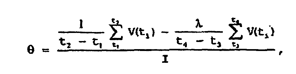 tk (k = 1,..., 4) sont des instants après que l'émetteur a été déconnecté, t1 < t2 représentant la partie initiale du signal et t3 < t4 représentant la dernière partie temporelle du signal,V(ti) sont les tensions qui représentent le signal total reçu par le récepteur à différents instants dans les intervalles [t1, t2] et [t3, t4],I est le courant qui excite l'émetteur,et Vc(ti) sont les tensions qui représentent le signal reçu par le récepteur et dû aux produits de corrosion à différents instants dans les intervalles [t1, t2] et [t3, t4].
Priority Applications (1)
| Application Number | Priority Date | Filing Date | Title |
|---|---|---|---|
| EP03709731A EP1478899B1 (fr) | 2002-02-26 | 2003-02-26 | Determiner le profil d'une surface d'un objet |
Applications Claiming Priority (4)
| Application Number | Priority Date | Filing Date | Title |
|---|---|---|---|
| EP02075765 | 2002-02-26 | ||
| EP02075765 | 2002-02-26 | ||
| EP03709731A EP1478899B1 (fr) | 2002-02-26 | 2003-02-26 | Determiner le profil d'une surface d'un objet |
| PCT/EP2003/002040 WO2003073040A2 (fr) | 2002-02-26 | 2003-02-26 | Determiner le profil d'une surface d'un objet |
Publications (2)
| Publication Number | Publication Date |
|---|---|
| EP1478899A2 EP1478899A2 (fr) | 2004-11-24 |
| EP1478899B1 true EP1478899B1 (fr) | 2005-12-07 |
Family
ID=27763400
Family Applications (1)
| Application Number | Title | Priority Date | Filing Date |
|---|---|---|---|
| EP03709731A Expired - Lifetime EP1478899B1 (fr) | 2002-02-26 | 2003-02-26 | Determiner le profil d'une surface d'un objet |
Country Status (12)
| Country | Link |
|---|---|
| US (1) | US6734670B2 (fr) |
| EP (1) | EP1478899B1 (fr) |
| JP (1) | JP2005518534A (fr) |
| CN (1) | CN1307401C (fr) |
| AT (1) | ATE312334T1 (fr) |
| AU (1) | AU2003214081A1 (fr) |
| CA (1) | CA2477263A1 (fr) |
| DE (1) | DE60302653T2 (fr) |
| ES (1) | ES2254911T3 (fr) |
| NO (1) | NO20044056L (fr) |
| RU (1) | RU2299399C2 (fr) |
| WO (1) | WO2003073040A2 (fr) |
Families Citing this family (26)
| Publication number | Priority date | Publication date | Assignee | Title |
|---|---|---|---|---|
| US6703831B1 (en) * | 1999-11-12 | 2004-03-09 | Quantech, Inc. | Dual eddy current probe for detecting geometrical differences especially as related to threaded apertures and studs |
| US7696748B2 (en) * | 2003-10-10 | 2010-04-13 | Jentek Sensors, Inc. | Absolute property measurements using electromagnetic sensors |
| JP4394415B2 (ja) * | 2003-10-24 | 2010-01-06 | 非破壊検査株式会社 | 電磁波パルスによる板厚相対比較方法及び板厚相対比較装置 |
| US8013599B2 (en) * | 2004-11-19 | 2011-09-06 | General Electric Company | Methods and apparatus for testing a component |
| FR2900471B1 (fr) * | 2006-04-26 | 2008-12-26 | Snecma Sa | Mesure des epaisseurs de paroi, notamment d'aube, par courants de foucault |
| FR2904694B1 (fr) * | 2006-08-03 | 2008-11-07 | Commissariat Energie Atomique | Procede et dispositif de controle par courants de foucault a fonctions emission/reception separees d'une piece electriquement conductrice |
| MX2009003069A (es) | 2006-09-21 | 2009-04-01 | Shell Int Research | Dispositivo y metodo para detectar una anomalia en un montaje de un primer y un segundo objeto. |
| GB2450112B (en) * | 2007-06-12 | 2010-12-08 | Ge Inspection Technologies Ltd | Automatic lift-off compensation for pulsed eddy current inspection |
| JP5017038B2 (ja) * | 2007-09-26 | 2012-09-05 | 株式会社日立製作所 | 渦流検査装置及び渦流検査方法 |
| JP5200513B2 (ja) * | 2007-11-30 | 2013-06-05 | 新日鐵住金株式会社 | 溶接部の非破壊検査装置、及び溶接部の非破壊検査方法 |
| US9109330B2 (en) * | 2009-03-09 | 2015-08-18 | Honeywell International Inc. | Apparatus and method for measuring properties of unstabilized moving sheets |
| JP5387718B2 (ja) * | 2011-05-30 | 2014-01-15 | Jfeスチール株式会社 | 磁気特性測定方法および磁気特性測定装置 |
| CN102445567B (zh) * | 2011-10-12 | 2013-06-26 | 上海华力微电子有限公司 | 一种电子扫描显微镜环境磁场的监测方法 |
| JP5299800B2 (ja) * | 2011-10-25 | 2013-09-25 | 新日鐵住金株式会社 | 浸炭検知方法 |
| GB201203717D0 (en) * | 2012-03-02 | 2012-04-18 | Speir Hunter Ltd | Fault detection for pipelines |
| US9091664B2 (en) * | 2012-06-07 | 2015-07-28 | Thomas Krause | Pulsed eddy current sensor for precision measurement at-large lift-offs on metallic surfaces |
| GB2527988B (en) * | 2013-03-15 | 2018-09-05 | Aegion Coating Services Llc | Pipe outer surface inspection apparatus |
| JP6271336B2 (ja) * | 2014-05-22 | 2018-01-31 | 日立Geニュークリア・エナジー株式会社 | 渦電流検査装置及び渦電流検査方法 |
| FR3025306B1 (fr) * | 2014-08-29 | 2020-07-10 | Safran | Procede non-destructif de mesure de l'epaisseur de barriere thermique et/ou de mur en superalliage d'aube creuse de turbomachine |
| US20170241953A1 (en) * | 2014-11-21 | 2017-08-24 | Konica Minolta, Inc. | Magnetic flaw detection device and magnetic flaw detection method |
| CN106247171B (zh) * | 2015-06-12 | 2019-10-22 | 宁波市鄞州磁泰电子科技有限公司 | 管道缺陷检测方法、管道缺陷检测装置和管道缺陷检测设备 |
| CN106707392B (zh) * | 2016-12-07 | 2019-02-01 | 友达光电(昆山)有限公司 | 彩色滤光片及其膜层厚度测量方法 |
| GB2566548B (en) * | 2017-09-19 | 2022-04-13 | Elcometer Ltd | Surface profile measuring instrument and method |
| EP3647714B1 (fr) * | 2018-11-01 | 2021-01-27 | Airbus Defence and Space GmbH | Dispositif capteur, dispositif de captage, procédé de détermination et procédé de captage permettant de déterminer une position relative ou de capter un objet dans l'espace |
| CN113984887B (zh) * | 2021-10-29 | 2024-02-09 | 中国航发北京航空材料研究院 | 一种利用涡流自动检测系统在线获取盘件轮廓的方法 |
| KR102663363B1 (ko) | 2023-07-21 | 2024-05-08 | 대한민국 | 벽체의 면 외 방향 변위 측정장치 및 측정방법 |
Family Cites Families (10)
| Publication number | Priority date | Publication date | Assignee | Title |
|---|---|---|---|---|
| GB2112944A (en) * | 1982-01-05 | 1983-07-27 | James C Taylor | Calibration of thickness gauges |
| US4843320A (en) * | 1987-12-17 | 1989-06-27 | Atlantic Richfield Company | Transient electromagnetic method for detecting corrosion on conductive containers |
| US5200704A (en) * | 1991-02-28 | 1993-04-06 | Westinghouse Electric Corp. | System and method including a buried flexible sheet target impregnated with ferromagnetic particles and eddy current probe for determining proximity of a non-conductive underground structure |
| US5854553A (en) * | 1996-06-19 | 1998-12-29 | Skf Condition Monitoring | Digitally linearizing eddy current probe |
| US6291992B1 (en) * | 1996-07-12 | 2001-09-18 | Shell Oil Company | Eddy current inspection technique |
| US6285183B1 (en) * | 1996-09-30 | 2001-09-04 | Mcdonnell Douglas Corporation | Method and system for measuring the volume loss of a metal substrate |
| US6037768A (en) * | 1997-04-02 | 2000-03-14 | Iowa State University Research Foundation, Inc. | Pulsed eddy current inspections and the calibration and display of inspection results |
| DE19860487A1 (de) * | 1998-12-28 | 2000-07-06 | Siemens Ag | Verfahren und Vorrichtung zur räumlichen Vermessung einer Inhomogenität an einer Oberfläche eines Kernreaktorbauteils und Anwendung des Verfahrens zur Vermessung einer elektrisch praktisch nicht leitenden Schicht |
| US6344741B1 (en) * | 2000-06-20 | 2002-02-05 | Her Majesty The Queen As Represented By The Minister Of National Defence In Right Of Canada | Pulsed eddy current method for detection of corrosion in multilayer structures using the lift-off point of intersection |
| US6570379B2 (en) * | 2000-08-24 | 2003-05-27 | Shell Oil Company | Method for inspecting an object of electrically conducting material |
-
2003
- 2003-02-26 CN CNB038047063A patent/CN1307401C/zh not_active Expired - Fee Related
- 2003-02-26 ES ES03709731T patent/ES2254911T3/es not_active Expired - Lifetime
- 2003-02-26 DE DE60302653T patent/DE60302653T2/de not_active Expired - Lifetime
- 2003-02-26 US US10/375,804 patent/US6734670B2/en not_active Expired - Lifetime
- 2003-02-26 CA CA002477263A patent/CA2477263A1/fr not_active Abandoned
- 2003-02-26 WO PCT/EP2003/002040 patent/WO2003073040A2/fr active IP Right Grant
- 2003-02-26 EP EP03709731A patent/EP1478899B1/fr not_active Expired - Lifetime
- 2003-02-26 AU AU2003214081A patent/AU2003214081A1/en not_active Abandoned
- 2003-02-26 RU RU2004128445/28A patent/RU2299399C2/ru not_active IP Right Cessation
- 2003-02-26 AT AT03709731T patent/ATE312334T1/de not_active IP Right Cessation
- 2003-02-26 JP JP2003571682A patent/JP2005518534A/ja not_active Ceased
-
2004
- 2004-09-24 NO NO20044056A patent/NO20044056L/no not_active Application Discontinuation
Also Published As
| Publication number | Publication date |
|---|---|
| EP1478899A2 (fr) | 2004-11-24 |
| CN1639538A (zh) | 2005-07-13 |
| CN1307401C (zh) | 2007-03-28 |
| WO2003073040A2 (fr) | 2003-09-04 |
| AU2003214081A1 (en) | 2003-09-09 |
| US6734670B2 (en) | 2004-05-11 |
| NO20044056L (no) | 2004-09-24 |
| DE60302653D1 (de) | 2006-01-12 |
| AU2003214081A8 (en) | 2003-09-09 |
| DE60302653T2 (de) | 2006-06-14 |
| JP2005518534A (ja) | 2005-06-23 |
| US20030169035A1 (en) | 2003-09-11 |
| ES2254911T3 (es) | 2006-06-16 |
| CA2477263A1 (fr) | 2003-09-04 |
| ATE312334T1 (de) | 2005-12-15 |
| WO2003073040A3 (fr) | 2004-03-11 |
| RU2299399C2 (ru) | 2007-05-20 |
| RU2004128445A (ru) | 2005-05-27 |
Similar Documents
| Publication | Publication Date | Title |
|---|---|---|
| EP1478899B1 (fr) | Determiner le profil d'une surface d'un objet | |
| EP1311800B1 (fr) | Mesure de l'epaisseur de la paroi d'un objet electriquement conducteur | |
| US4843320A (en) | Transient electromagnetic method for detecting corrosion on conductive containers | |
| EP1311842B1 (fr) | Controle d'un objet constitue d'un materiau electroconducteur | |
| JP5383597B2 (ja) | 渦電流検査装置および検査方法 | |
| JP4455343B2 (ja) | 壁厚の監視 | |
| US4881031A (en) | Eddy current method and apparatus for determining structural defects in a metal object without removing surface films or coatings | |
| CN109521087A (zh) | 一种带包覆层铁磁管道壁厚腐蚀的脉冲涡流检测方法 | |
| JPH0771905A (ja) | 核燃料棒に析出した強磁性物質の厚みを決定する方法 | |
| US5847562A (en) | Thickness gauging of single-layer conductive materials with two-point non linear calibration algorithm | |
| JP5692007B2 (ja) | 溶射皮膜の品質評価方法 | |
| JPH09113488A (ja) | 電磁気的材質評価方法及び装置 | |
| Al-Qadeeb | Tubing inspection using multiple NDT techniques | |
| CN108489374B (zh) | 一种双模式铁磁包覆层管道壁厚检测方法 | |
| Goldfine et al. | MWM®-Array Electromagnetic Techniques for Crack Sizing, Weld Assessment, Wall Loss/Thickness Measurement, and Mechanical Damage Profilometry | |
| Terekhin et al. | Evaluating specific electrical conductivity of two-layered nonmagnetic objects by pulsed eddy-current method | |
| JP7374032B2 (ja) | 電磁気測定による厚さ測定用マスターカーブの作成方法とその使用方法 | |
| Olympus Europa SE & Co. KG | Getting the Right Tool for Every Application | |
| Dmitriev et al. | Research of Steel-dielectric Transition Using Subminiature Eddy-current Transducer | |
| Kania et al. | Investigation and Assessment of Low-Frequency ERW Seam Imperfections by EMAT and CMFL ILI | |
| Malikov et al. | Measurement System for Studying Thickness by Means of Subminiature Eddy-Current Transducers | |
| Zhang et al. | A thickness measuring strategy for coating in hemispherical steel shells with EC-laser combined sensors | |
| Dmitriev et al. | Subminiature eddy-current transducers for thickness studies | |
| Casper et al. | Pulsed Eddy Current Testing | |
| Kania et al. | On the assessment of low-frequency electric-resistance-welded linepipe defects by EMAT and CMFL in-line inspection. |
Legal Events
| Date | Code | Title | Description |
|---|---|---|---|
| PUAI | Public reference made under article 153(3) epc to a published international application that has entered the european phase |
Free format text: ORIGINAL CODE: 0009012 |
|
| 17P | Request for examination filed |
Effective date: 20040824 |
|
| AK | Designated contracting states |
Kind code of ref document: A2 Designated state(s): AT BE BG CH CY CZ DE DK EE ES FI FR GB GR HU IE IT LI LU MC NL PT SE SI SK TR |
|
| AX | Request for extension of the european patent |
Extension state: AL LT LV MK RO |
|
| GRAP | Despatch of communication of intention to grant a patent |
Free format text: ORIGINAL CODE: EPIDOSNIGR1 |
|
| GRAS | Grant fee paid |
Free format text: ORIGINAL CODE: EPIDOSNIGR3 |
|
| GRAA | (expected) grant |
Free format text: ORIGINAL CODE: 0009210 |
|
| AK | Designated contracting states |
Kind code of ref document: B1 Designated state(s): AT BE BG CH CY CZ DE DK EE ES FI FR GB GR HU IE IT LI LU MC NL PT SE SI SK TR |
|
| PG25 | Lapsed in a contracting state [announced via postgrant information from national office to epo] |
Ref country code: CZ Free format text: LAPSE BECAUSE OF FAILURE TO SUBMIT A TRANSLATION OF THE DESCRIPTION OR TO PAY THE FEE WITHIN THE PRESCRIBED TIME-LIMIT Effective date: 20051207 Ref country code: CH Free format text: LAPSE BECAUSE OF FAILURE TO SUBMIT A TRANSLATION OF THE DESCRIPTION OR TO PAY THE FEE WITHIN THE PRESCRIBED TIME-LIMIT Effective date: 20051207 Ref country code: AT Free format text: LAPSE BECAUSE OF FAILURE TO SUBMIT A TRANSLATION OF THE DESCRIPTION OR TO PAY THE FEE WITHIN THE PRESCRIBED TIME-LIMIT Effective date: 20051207 Ref country code: FI Free format text: LAPSE BECAUSE OF FAILURE TO SUBMIT A TRANSLATION OF THE DESCRIPTION OR TO PAY THE FEE WITHIN THE PRESCRIBED TIME-LIMIT Effective date: 20051207 Ref country code: SK Free format text: LAPSE BECAUSE OF FAILURE TO SUBMIT A TRANSLATION OF THE DESCRIPTION OR TO PAY THE FEE WITHIN THE PRESCRIBED TIME-LIMIT Effective date: 20051207 Ref country code: LI Free format text: LAPSE BECAUSE OF FAILURE TO SUBMIT A TRANSLATION OF THE DESCRIPTION OR TO PAY THE FEE WITHIN THE PRESCRIBED TIME-LIMIT Effective date: 20051207 Ref country code: SI Free format text: LAPSE BECAUSE OF FAILURE TO SUBMIT A TRANSLATION OF THE DESCRIPTION OR TO PAY THE FEE WITHIN THE PRESCRIBED TIME-LIMIT Effective date: 20051207 |
|
| REG | Reference to a national code |
Ref country code: GB Ref legal event code: FG4D |
|
| REG | Reference to a national code |
Ref country code: CH Ref legal event code: EP |
|
| REG | Reference to a national code |
Ref country code: IE Ref legal event code: FG4D |
|
| REF | Corresponds to: |
Ref document number: 60302653 Country of ref document: DE Date of ref document: 20060112 Kind code of ref document: P |
|
| PG25 | Lapsed in a contracting state [announced via postgrant information from national office to epo] |
Ref country code: IE Free format text: LAPSE BECAUSE OF NON-PAYMENT OF DUE FEES Effective date: 20060227 |
|
| PG25 | Lapsed in a contracting state [announced via postgrant information from national office to epo] |
Ref country code: LU Free format text: LAPSE BECAUSE OF NON-PAYMENT OF DUE FEES Effective date: 20060228 Ref country code: MC Free format text: LAPSE BECAUSE OF NON-PAYMENT OF DUE FEES Effective date: 20060228 |
|
| PG25 | Lapsed in a contracting state [announced via postgrant information from national office to epo] |
Ref country code: SE Free format text: LAPSE BECAUSE OF FAILURE TO SUBMIT A TRANSLATION OF THE DESCRIPTION OR TO PAY THE FEE WITHIN THE PRESCRIBED TIME-LIMIT Effective date: 20060307 Ref country code: BG Free format text: LAPSE BECAUSE OF FAILURE TO SUBMIT A TRANSLATION OF THE DESCRIPTION OR TO PAY THE FEE WITHIN THE PRESCRIBED TIME-LIMIT Effective date: 20060307 Ref country code: GR Free format text: LAPSE BECAUSE OF FAILURE TO SUBMIT A TRANSLATION OF THE DESCRIPTION OR TO PAY THE FEE WITHIN THE PRESCRIBED TIME-LIMIT Effective date: 20060307 Ref country code: DK Free format text: LAPSE BECAUSE OF FAILURE TO SUBMIT A TRANSLATION OF THE DESCRIPTION OR TO PAY THE FEE WITHIN THE PRESCRIBED TIME-LIMIT Effective date: 20060307 |
|
| PG25 | Lapsed in a contracting state [announced via postgrant information from national office to epo] |
Ref country code: PT Free format text: LAPSE BECAUSE OF FAILURE TO SUBMIT A TRANSLATION OF THE DESCRIPTION OR TO PAY THE FEE WITHIN THE PRESCRIBED TIME-LIMIT Effective date: 20060508 |
|
| PG25 | Lapsed in a contracting state [announced via postgrant information from national office to epo] |
Ref country code: HU Free format text: LAPSE BECAUSE OF FAILURE TO SUBMIT A TRANSLATION OF THE DESCRIPTION OR TO PAY THE FEE WITHIN THE PRESCRIBED TIME-LIMIT Effective date: 20060608 |
|
| REG | Reference to a national code |
Ref country code: CH Ref legal event code: PL |
|
| REG | Reference to a national code |
Ref country code: ES Ref legal event code: FG2A Ref document number: 2254911 Country of ref document: ES Kind code of ref document: T3 |
|
| ET | Fr: translation filed | ||
| PLBE | No opposition filed within time limit |
Free format text: ORIGINAL CODE: 0009261 |
|
| STAA | Information on the status of an ep patent application or granted ep patent |
Free format text: STATUS: NO OPPOSITION FILED WITHIN TIME LIMIT |
|
| 26N | No opposition filed |
Effective date: 20060908 |
|
| REG | Reference to a national code |
Ref country code: IE Ref legal event code: MM4A |
|
| PG25 | Lapsed in a contracting state [announced via postgrant information from national office to epo] |
Ref country code: EE Free format text: LAPSE BECAUSE OF FAILURE TO SUBMIT A TRANSLATION OF THE DESCRIPTION OR TO PAY THE FEE WITHIN THE PRESCRIBED TIME-LIMIT Effective date: 20051207 |
|
| PG25 | Lapsed in a contracting state [announced via postgrant information from national office to epo] |
Ref country code: TR Free format text: LAPSE BECAUSE OF FAILURE TO SUBMIT A TRANSLATION OF THE DESCRIPTION OR TO PAY THE FEE WITHIN THE PRESCRIBED TIME-LIMIT Effective date: 20051207 |
|
| PG25 | Lapsed in a contracting state [announced via postgrant information from national office to epo] |
Ref country code: CY Free format text: LAPSE BECAUSE OF FAILURE TO SUBMIT A TRANSLATION OF THE DESCRIPTION OR TO PAY THE FEE WITHIN THE PRESCRIBED TIME-LIMIT Effective date: 20051207 |
|
| PGFP | Annual fee paid to national office [announced via postgrant information from national office to epo] |
Ref country code: ES Payment date: 20100222 Year of fee payment: 8 Ref country code: FR Payment date: 20091223 Year of fee payment: 8 |
|
| PGFP | Annual fee paid to national office [announced via postgrant information from national office to epo] |
Ref country code: IT Payment date: 20100121 Year of fee payment: 8 |
|
| PGFP | Annual fee paid to national office [announced via postgrant information from national office to epo] |
Ref country code: BE Payment date: 20091224 Year of fee payment: 8 Ref country code: DE Payment date: 20091224 Year of fee payment: 8 |
|
| BERE | Be: lapsed |
Owner name: *SHELL INTERNATIONALE RESEARCH MAATSCHAPPIJ B.V. Effective date: 20110228 |
|
| REG | Reference to a national code |
Ref country code: FR Ref legal event code: ST Effective date: 20111102 |
|
| PG25 | Lapsed in a contracting state [announced via postgrant information from national office to epo] |
Ref country code: BE Free format text: LAPSE BECAUSE OF NON-PAYMENT OF DUE FEES Effective date: 20110228 |
|
| PG25 | Lapsed in a contracting state [announced via postgrant information from national office to epo] |
Ref country code: IT Free format text: LAPSE BECAUSE OF NON-PAYMENT OF DUE FEES Effective date: 20110226 |
|
| REG | Reference to a national code |
Ref country code: DE Ref legal event code: R119 Ref document number: 60302653 Country of ref document: DE Effective date: 20110901 |
|
| PG25 | Lapsed in a contracting state [announced via postgrant information from national office to epo] |
Ref country code: FR Free format text: LAPSE BECAUSE OF NON-PAYMENT OF DUE FEES Effective date: 20110228 |
|
| REG | Reference to a national code |
Ref country code: ES Ref legal event code: FD2A Effective date: 20120411 |
|
| PG25 | Lapsed in a contracting state [announced via postgrant information from national office to epo] |
Ref country code: ES Free format text: LAPSE BECAUSE OF NON-PAYMENT OF DUE FEES Effective date: 20110227 |
|
| PG25 | Lapsed in a contracting state [announced via postgrant information from national office to epo] |
Ref country code: DE Free format text: LAPSE BECAUSE OF NON-PAYMENT OF DUE FEES Effective date: 20110901 |
|
| REG | Reference to a national code |
Ref country code: GB Ref legal event code: 732E Free format text: REGISTERED BETWEEN 20150827 AND 20150902 |
|
| REG | Reference to a national code |
Ref country code: NL Ref legal event code: PD Owner name: TUEV RHEINLAND SONOVATION HOLDING B.V.; NL Free format text: DETAILS ASSIGNMENT: VERANDERING VAN EIGENAAR(S), OVERDRACHT; FORMER OWNER NAME: SHELL INTERNATIONALE RESEARCH MAATSCHAPPIJ B.V. Effective date: 20150923 |
|
| PGFP | Annual fee paid to national office [announced via postgrant information from national office to epo] |
Ref country code: NL Payment date: 20160225 Year of fee payment: 14 |
|
| PGFP | Annual fee paid to national office [announced via postgrant information from national office to epo] |
Ref country code: GB Payment date: 20160226 Year of fee payment: 14 |
|
| REG | Reference to a national code |
Ref country code: NL Ref legal event code: MM Effective date: 20170301 |
|
| GBPC | Gb: european patent ceased through non-payment of renewal fee |
Effective date: 20170226 |
|
| PG25 | Lapsed in a contracting state [announced via postgrant information from national office to epo] |
Ref country code: NL Free format text: LAPSE BECAUSE OF NON-PAYMENT OF DUE FEES Effective date: 20170301 |
|
| PG25 | Lapsed in a contracting state [announced via postgrant information from national office to epo] |
Ref country code: GB Free format text: LAPSE BECAUSE OF NON-PAYMENT OF DUE FEES Effective date: 20170226 |