EP1473685B1 - Eigensicheres Feldgerätwartungswerkzeug - Google Patents
Eigensicheres Feldgerätwartungswerkzeug Download PDFInfo
- Publication number
- EP1473685B1 EP1473685B1 EP04252479A EP04252479A EP1473685B1 EP 1473685 B1 EP1473685 B1 EP 1473685B1 EP 04252479 A EP04252479 A EP 04252479A EP 04252479 A EP04252479 A EP 04252479A EP 1473685 B1 EP1473685 B1 EP 1473685B1
- Authority
- EP
- European Patent Office
- Prior art keywords
- power
- island
- islands
- power island
- voltage
- Prior art date
- Legal status (The legal status is an assumption and is not a legal conclusion. Google has not performed a legal analysis and makes no representation as to the accuracy of the status listed.)
- Expired - Lifetime
Links
Images

Classifications
-
- G—PHYSICS
- G08—SIGNALLING
- G08C—TRANSMISSION SYSTEMS FOR MEASURED VALUES, CONTROL OR SIMILAR SIGNALS
- G08C19/00—Electric signal transmission systems
- G08C19/02—Electric signal transmission systems in which the signal transmitted is magnitude of current or voltage
-
- G—PHYSICS
- G05—CONTROLLING; REGULATING
- G05B—CONTROL OR REGULATING SYSTEMS IN GENERAL; FUNCTIONAL ELEMENTS OF SUCH SYSTEMS; MONITORING OR TESTING ARRANGEMENTS FOR SUCH SYSTEMS OR ELEMENTS
- G05B19/00—Program-control systems
- G05B19/02—Program-control systems electric
- G05B19/04—Program control other than numerical control, i.e. in sequence controllers or logic controllers
- G05B19/042—Program control other than numerical control, i.e. in sequence controllers or logic controllers using digital processors
- G05B19/0426—Programming the control sequence
-
- G—PHYSICS
- G05—CONTROLLING; REGULATING
- G05B—CONTROL OR REGULATING SYSTEMS IN GENERAL; FUNCTIONAL ELEMENTS OF SUCH SYSTEMS; MONITORING OR TESTING ARRANGEMENTS FOR SUCH SYSTEMS OR ELEMENTS
- G05B23/00—Testing or monitoring of control systems or parts thereof
- G05B23/02—Electric testing or monitoring
- G05B23/0205—Electric testing or monitoring by means of a monitoring system capable of detecting and responding to faults
- G05B23/0208—Electric testing or monitoring by means of a monitoring system capable of detecting and responding to faults characterized by the configuration of the monitoring system
- G05B23/0213—Modular or universal configuration of the monitoring system, e.g. monitoring system having modules that may be combined to build monitoring program; monitoring system that can be applied to legacy systems; adaptable monitoring system; using different communication protocols
-
- G—PHYSICS
- G05—CONTROLLING; REGULATING
- G05B—CONTROL OR REGULATING SYSTEMS IN GENERAL; FUNCTIONAL ELEMENTS OF SUCH SYSTEMS; MONITORING OR TESTING ARRANGEMENTS FOR SUCH SYSTEMS OR ELEMENTS
- G05B2219/00—Program-control systems
- G05B2219/20—Pc systems
- G05B2219/23—Pc programming
- G05B2219/23067—Control, human or man machine interface, interactive, HMI, MMI
-
- G—PHYSICS
- G05—CONTROLLING; REGULATING
- G05B—CONTROL OR REGULATING SYSTEMS IN GENERAL; FUNCTIONAL ELEMENTS OF SUCH SYSTEMS; MONITORING OR TESTING ARRANGEMENTS FOR SUCH SYSTEMS OR ELEMENTS
- G05B2219/00—Program-control systems
- G05B2219/20—Pc systems
- G05B2219/23—Pc programming
- G05B2219/23406—Programmer device, portable, handheld detachable programmer
-
- G—PHYSICS
- G05—CONTROLLING; REGULATING
- G05B—CONTROL OR REGULATING SYSTEMS IN GENERAL; FUNCTIONAL ELEMENTS OF SUCH SYSTEMS; MONITORING OR TESTING ARRANGEMENTS FOR SUCH SYSTEMS OR ELEMENTS
- G05B2219/00—Program-control systems
- G05B2219/20—Pc systems
- G05B2219/25—Pc structure of the system
- G05B2219/25006—Interface connected to fieldbus
-
- G—PHYSICS
- G05—CONTROLLING; REGULATING
- G05B—CONTROL OR REGULATING SYSTEMS IN GENERAL; FUNCTIONAL ELEMENTS OF SUCH SYSTEMS; MONITORING OR TESTING ARRANGEMENTS FOR SUCH SYSTEMS OR ELEMENTS
- G05B2219/00—Program-control systems
- G05B2219/20—Pc systems
- G05B2219/25—Pc structure of the system
- G05B2219/25428—Field device
Definitions
- Intrinsically safe field maintenance tools are known. Such tools are highly useful in the process control and measurement industry to allow operators to conveniently communicate with and/or interrogate field devices in a given process installation. Examples of such process installations include petroleum, pharmaceutical, chemical, pulp and other processing installations. In such installations, the process control and measurement network may include tens or even hundreds of various field devices which periodically require maintenance to ensure that such devices are functioning properly and/or calibrated. Moreover, when one or more errors in the process control and measurement installation is detected, the use of an intrinsically safe hand held field maintenance tool allows technicians to quickly diagnose such errors in the field.
- Model 275 HART® Communicator available from Fisher-Rosemount Systems, Inc., of Eden Prairie, Minnesota.
- HART® is a registered trademark of the HART® Communication Foundation.
- the Model 275 provides a host of important functions and capabilities and generally allows highly effective field maintenance. However, the Model 275 does not currently support communication with non-HART ® (Highway Addressable Remote Transducer) devices.
- the HART ® protocol has a hybrid physical layer consisting of digital communication signals superimposed on the standard 4-20 mA analog signal.
- the data transmission rate is approximately 1.2 Kbits/SEC.
- HART ® communication is one of the primary communication protocols in process industries.
- FOUNDATION TM Fieldbus Another major process industry communication protocol is known as the FOUNDATION TM fieldbus communication protocol. This protocol is based on an ISA standard (ISA-S50.01-1992, promulgated by the Instrument Society of America in 1992). A practical implementation was specified by the Fieldbus Foundation (FF). FOUNDATION TM Fieldbus is an all-digital communication protocol with a transmission rate of approximately 31.25 Kbits/SEC.
- US patent application US2002/0167904 describes a hand held communicator to communicate with a process control loop and, in turn, one or more connected filed units.
- a problem with this device is that it does nothing to limit the current through any particular component of the device.
- the device of US2002/0167904 can be improved to meet better the requirements for an intrinsically safe hand held communicator.
- a hand held configurator for coupling to a two wire process control loop is provided for use in configuring and monitoring field units coupled to the two wire process control loop.
- the configurator includes a power supply, loop coupling circuitry configured to couple to the two wire process control loop and at least two power islands which are configured to electrically isolate electrical components in one power island from electrical components in another power island. Independent power connections are provided between each power island and the power supply.
- a series resistor electrically connects two power islands to limit energy transfer therebetween.
- An improved intrinsically safe field maintenance tool in accordance with embodiments of the present invention is operable with at least two industry standard device descriptions.
- the tool includes at least two power islands which are electrically isolated in a manner to meet intrinsic safety requirements.
- an improved intrinsically safe field maintenance tool implements both HART® and fieldbus Device Description Language (DDL).
- DDL Device Description Language
- the improved field maintenance tool is used to maintain both two-wire and four-wire (i.e. external power) field devices using these protocols.
- both configuration and calibration are supported via DDL technology.
- DDL technology is known and additional reading regarding Device Description Language can be found in U.S. Patent 5,960,214 to Sharp, Jr. et al.
- the improved intrinsically safe field maintenance tool also facilitates a convenient display of diagnostic information from individual field devices (i.e. status bits) as well as providing advanced protocol-specific network troubleshooting features. Further details and benefits of the improved intrinsically safe field maintenance tool in accordance with embodiments of the present invention will be appreciated after reading the description below.
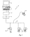
- Fig. 1 illustrates an exemplary system in which embodiments of the present invention are useful.
- System 10 includes controller 12, I/O and control sub-system 14, intrinsic safety (IS) barrier 16, process communication loop 18 and field devices 20.
- Controller 12 is coupled to I/O and control sub-system 14 via link 21 which can be any suitable link such as a local area network (LAN) operating in accordance with Ethernet signaling protocols or any other suitable protocol.
- I/O and control sub-system 14 is coupled to intrinsic safety barrier 16 which in turn is coupled to process communication loop 18 to allow data communication between loop 18 and I/O and control sub-system 14 in a manner that limits energy passing therethrough.
- LAN local area network
- process communication or process control loop 18 is a FOUNDATIONTM fieldbus process communication loop and is coupled to field devices 20, which are shown coupled arranged in a multi-drop configuration.
- An alternative process communication loop (not shown) is an HART® process communication loop.
- Fig. 1 illustrates a multi-drop wiring configuration that vastly simplifies system wiring compared to other topologies such as the star topology. Multi-drop HART® configurations support a maximum of 15 devices, while multi-drop FOUNDATIONTM Fieldbus configurations support a maximum of 32 devices.
- Intrinsically safe field maintenance tool 22 is coupled to loop 18 as illustrated in Fig. 1 .
- tool 22 can perform a number of the communication and diagnostic functions.
- Tool 22 can couple to and interact with HART® process communication loops in much the same way the presently available Model 275 HART® Communicator can.
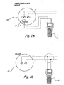
- Fig. 2A illustrates tool 22 coupled to HART®-compatible device 20 via terminals 24.
- tool 22 can communicate with a HART® compatible device on the process instrumentation communication loop, such as device 24 via the loop itself, as indicated in Fig. 2B .
- Fig. 3 is a diagrammatic view of field maintenance tool 22 in accordance with embodiments of the present invention.
- tool 22 preferably includes three communication terminals 26, 28 and 30 which facilitate coupling tool 22 to process communication loops and/or devices in accordance with at least two process industry standard protocols.
- first process industry standard protocol such coupling is effected using terminal 26 and common terminal 28.
- media access unit 32 which is configured to interact upon the process communication loop in accordance with the first industry standard protocol.
- tool 22 is to be coupled to a process and control measurement loop that operates in accordance with a second industry standard protocol, such connection is made via common terminal 28 and terminal 30.
- connection is effected via the second media access unit 34 which is configured to interact upon the process communication loop in accordance with the second industry standard protocol.
- Both media access units 32 and 34 are coupled to processor 36 which receives data from one of the media access units and interprets that data accordingly.
- Processor 36 is also coupled to keypad module 38 and display module 40.
- Keypad module 38 is coupled to the keypad on the housing of tool 22 in order to receive various keypad inputs from a user.
- Display module 40 is coupled to the display to provide data and/or a user interface.
- tool 22 includes additional hardware enhancements that facilitate increased functionality over that generally available in the prior art.
- tool 22 includes infrared data access port 42 which is coupled to processor 36 to allow tool 22 to transfer information to and from a separate device using infrared wireless communication.
- port 42 is for transferring and/or updating Device Descriptions stored in one or more memories of tool 22.
- a Device Description (DD) is a software technology used to describe parameters in a field device in a computer-readable format. This contains all of the information necessary for a software application being executed on processor 36 to retrieve and use the parametric data.
- the separate device such as computer 12, can obtain a new Device Description from floppy disk, CD ROM, or the internet and wirelessly transfer the new Device Description to tool 22.
- Removable memory module 44 is removably coupled to processor 36 via port/interface 46.
- Removable memory module 44 is adapted to store software applications that can be executed instead of primary applications on processor 36.
- module 44 may contain applications that use the HART® or FOUNDATIONTM fieldbus communication port, to provide a comprehensive diagnostic for a given process valve.
- module 44 may store software applications that aid in the calibration or configuration of specific devices.
- Module 44 may also store a software image for a new or updated primary device application that can subsequently be transferred into the non-volatile memory of device 36 to enable execution of the updated application.
- module 44 provides removable memory storage for the configuration of multiple devices allowing a field maintenance operator to acquire a relatively substantial amount of device data and conveniently store or transfer such data by simply removing module 44.
- module 44 is adapted to be replaceable in hazardous areas, in a process plant.
- module 44 comply with intrinsic safety requirements set forth in: APPROVAL STANDARD INTRINSICALLY SAFE APPARATUS AND ASSOCIATED APPARATUS FOR USE IN CLASS I, II AND III, DIVISION 1 HAZARDOUS (CLASSIFIED) LOCATIONS, CLASS NUMBER 3610, promulgated by Factory Mutual Research October, 1988.
- Adaptations to comply with additional industrial standards such as Canadian Standards Association (CSA) and the European CENELEC standards are also contemplated.
- Examples of specific structural adaptations for memory module 44 and/or interface 46 to facilitate compliance include energy limiting circuits such that the operating voltage level of memory module 44 is sufficiently low that stored energy within module 44 cannot generate a source of ignition. Additionally, module 44 may include current limiting circuitry to ensure that in the event that specific terminals on module 44 are shorted, that the discharge energy is sufficiently low that ignition is inhibited. Specific implementations of these features are set forth in connection with Figure 4 .
- Interface 44 may include physical characteristics that are specifically designed to prevent exposure of electrical contacts on memory module 44 to an external environment while simultaneously allowing suitable interface contacts to make electrical contact with module 44. For example, module 44 may include an over-modeling that can be pierced or otherwise displaced by coupling module 44 to interface 46.
- Tool 22 also preferably includes expansion memory module 48 coupled to processor 36 via connector 50 which is preferably disposed on the main board of tool 22.
- Expansion memory module 48 may contain Device Descriptions of first and second industry standard protocols. Module 48 may also contain license code(s) that will determine the functionality of tool 22 with respect to the multiple protocols. For example, data residing within module 48 may indicate that tool 22 is only authorized to operate within a single process industry standard mode, such as the HART® protocol. Ultimately, a different setting of that data within module 48 may indicate that tool 22 is authorized to operate in accordance with two or more industry standard protocols. Module 48 is preferably inserted to a connector 50 on the main board and may in fact require partial disassembly of tool 22, such as removing the battery pack to access port 50.
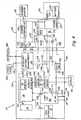
- FIG 4 is a more detailed block diagram of tool 22.
- Tool 22 generally includes power supply circuitry 100 and power islands 102, 104 and 106.
- the keypad 38 shown in Figure 3 is divided into a touch panel 38A and a keyboard 38B in Figure 4 .
- a charger/adapter 110 couples to power supply circuitry 100 as does a battery pack 112.
- Power supply circuitry 100 provides power to power islands 102, 104 and 106 using power received from charger/adapter 110 or battery pack 112.
- Battery pack 112 includes batteries 120 which couple to power supply circuitry 100 through a fuse 122.
- Power supply circuitry 100 includes charger interface circuitry 130, isolator 132, power supply circuitry 134, and voltage regulator 136.
- Power island 102 includes keyboard and battery management circuitry 140.
- Power island 104 includes processor 136.
- Power island 106 includes loop I/O circuitry 150 which implements MAU 32 and MAU 34 shown in Figure 3 .
- the infrared interface 42 is also located in power island 106.
- the power supply 100 and the power islands 102, 104 and 106 are isolated using passive and active techniques.
- Power supply 100 receives power from charger/adapter 110 or battery pack 112. When charger/adapter 110 is used power supply 100 charges battery 120 or battery pack 112.
- the power supply 100 is controlled by keyboard/battery management circuitry 140 and is isolated from circuitry 140 by isolator 132 which includes a plurality of resistors 160 and Zener diode 162. Resistors 160 act as passive current limiters and diode 162 act as passive voltage limiters.
- Power from battery pack 112 is provided to power island 102 through voltage regulator 136 and resistor 164.
- a Zener diode 166 connects the power connection to ground.
- Connection 172 from power supply 134 provides a power on/off connection.
- Active current limiters 174 and 176 couple power supply 134 to power islands 104 and 106, respectively.
- SCR 178 limits the voltage applied to current limiters 174 and 176.
- An electrical ground connection 180 is also provided between power supply circuitry 100 and power islands 102, 104 and 106.
- a power on/off connection 190 selectively closes switch 192 to thereby provide power to power island 106.
- Keyboard/battery management circuitry 140 couples to a touch pad panel 38A and a keyboard 38B and is configured to receive user input which is provided to processor 36 over connection 200 through a resistor 202. Circuitry 140 also couples to power connection 204 and 206 through resistors 208 and 210, respectively. These connections allow circuitry 140 to sense whether power is being supplied to power islands 104 and 106, respectively. Zener diodes 214 and 215 limit the voltage seen between the power islands.
- Power island 104 includes processor 36 which couples to infrared interface 42 through resistor 230 and to loop I/O circuitry 150 through resistor 232.
- Processor 36 also couples to display 40 through power island 106 and display drivers 240 and 242 and resistors 244 and 246.
- Loop I/O circuitry 150 of power island 106 receives power from a voltage regulator 250 through resistors 252 and 254.
- a Zener diode 256 limits the voltage applied to circuitry 150.
- the surface temperature of small components under fault conditions be limited. Limiting component surface temperature will prevent ignition of surrounding material. For example, if the total surface area of a component is 20mm 2 , the power dissipation by the component must be limited to 1.3 watts. For systems with higher total power consumption, it is necessary to split the power between separate power islands. Using this power island technique, it is possible to exceed the 1.3 watt limit.
- the power islands 102, 104 and 106 are supplied power through separate power connections which are connected to separate power supplies or through barriers.
- the power source for each power island is limited by voltage and current barriers to ensure that the maximum allowed power draw is not exceeded.
- passive barriers are used, such as a resistor current limiter and a Zener diode voltage limiter, as well as active limiters.
- SCR 178 will close (short circuit) if the voltage exceeds a predetermined limit.
- current limiters 174 and 176 activate SCR 178 if the current draw exceeds a predetermined limit. In both cases if the voltage or current exceeds the limits, SCR 178 will be activated and short circuit the power supply output.
- ground routes are also provided from the islands such that all of the islands are coupled to the same ground. The ground routes must be sufficient to carry the largest possible current. If the ground routes are fabricated as traces on a circuit board, the width of the trace must be sufficient to carry the desired current. Alternatively, a multi-layered trace can be provided.
- increased voltages can be generated using a DC to DC converter if the voltage required is greater than that provided by the power supply.
- voltage regulator 250 can increase the voltage level provided from the power supply.
- the converter outputs are limited with voltage barriers which limit the maximum voltage applied. The greatest possible voltage value present in a particular island, along with the voltage of adjacent islands, defines the necessary spacing between the islands.
- a selection of the series resistors can effect the high frequency characteristics of the signal paths between islands.
- the resistance value together with the internal capacitance of the circuitry act as a high frequency filter.
- driver and level shifter circuits are preferably placed close to the series resistors an the island borders to thereby reduce the capacitance.
- a "subpower island” can be used to overcome this limitation.
- a subpower island is contained within a power island and is separated with a desired physical spacing. The same rules described above with respect to power islands are applied to the subpower island.
- Current limiting series resistors between the power island and the subpower island reduce the maximum possible power inside the subpower island.
- the maximum possible surface temperature of components inside the subpower island can be controlled by choosing the appropriate value of the current limiting series resistors.
- the signal paths between the power island and the subpower island thus reduce the power available within the subpower island.
- An example of subpower island is shown as loop I/O circuitry 150 in Figure 4 which is a part of power island 106. Resistors 232, 252 and 254 limit the maximum power which may be supplied to the subpower island 150.
Landscapes
- Physics & Mathematics (AREA)
- General Physics & Mathematics (AREA)
- Engineering & Computer Science (AREA)
- Automation & Control Theory (AREA)
- Arrangements For Transmission Of Measured Signals (AREA)
- Programmable Controllers (AREA)
- Testing Or Calibration Of Command Recording Devices (AREA)
- Earth Drilling (AREA)
- Excavating Of Shafts Or Tunnels (AREA)
- Bridges Or Land Bridges (AREA)
Claims (20)
- Handgeführter bzw. tragbarer Konfigurator (22) zur Kopplung an eine Zweidraht-Prozessregelschleife (18) zur Verwendung bei der Konfiguration und Überwachung von Feldeinheiten (20), welche an die Zweidraht-Prozessregelschleife (18) gekoppelt sind, wobei der Konfigurator Folgendes aufweist:eine Energieversorgung (134);eine Schleifenkopplungs-Schaltkreisanordnung, welche derart konfiguriert ist, dass sie an die Zweidraht-Prozessregelschleife (18) koppelt;dadurch gekennzeichnet, dass der handgeführte bzw. tragbare Konfigurator (22) des Weiteren Folgendes aufweist:mindestens zwei Leistungsinseln bzw. isolierte Netzwerke (102, 104, 106), welche derart konfiguriert sind, dass sie elektrische Bauteile in einer Leistungsinsel von elektrischen Bauteilen in einer anderen Leistungsinsel elektrisch isolieren;unabhängige Energie- bzw. Stromanschlüsse zwischen jeder Leistungsinsel und der Energieversorgung; undeinen Reihenwiderstand (202, 208, 210, 230, 232, 244, 246), welcher zwei Leistungsinseln (102, 104, 106) elektrisch verbindet, um eine Energieübertragung dazwischen zu begrenzen.
- Vorrichtung nach Anspruch 1, welche einen Strombegrenzer in mindestens einem Netzanschluss zur Begrenzung von an eine Leistungsinsel bzw. an ein isoliertes Netzwerk (102, 104, 106) gelieferten Strom einschließt.
- Vorrichtung nach Anspruch 1 oder Anspruch 2, welche einen Spannungsbegrenzer (162, 166, 178) einschließt, welcher an mindestens einen Netzanschluss zur Begrenzung von an die Leistungsinsel bzw. an das isolierte Netzwerk (102, 104, 106) angelegte Spannung gekoppelt ist.
- Vorrichtung nach einem der vorhergehenden Ansprüche, dadurch gekennzeichnet, dass zumindest eine der Leistungsinseln bzw. isolierten Netzwerke (102, 104, 106) eine Teilleistungsinsel (150) darin aufweist, welche durch einen gewünschten Abstand getrennt ist und an andere Bauelemente der Leistungsinsel über mindestens einen Reihenwiderstand (252, 254) gekoppelt ist.
- Vorrichtung nach einem der Ansprüche 2 bis 4, dadurch gekennzeichnet, dass der Strombegrenzer ein aktives Bauelement (174, 176) aufweist.
- Vorrichtung nach einem der Ansprüche 2 bis 4, dadurch gekennzeichnet, dass der Strombegrenzer ein passives Bauelement (160) aufweist.
- Vorrichtung nach einem der Ansprüche 3 bis 6, dadurch gekennzeichnet, dass der Spannungsbegrenzer ein aktives Bauelement (136) aufweist.
- Vorrichtung nach einem der Ansprüche 3 bis 6, dadurch gekennzeichnet, dass der Spannungsbegrenzer ein passives Bauelement (162, 166, 178) aufweist.
- Vorrichtung nach einem der vorhergehenden Ansprüche, dadurch gekennzeichnet, dass mindestens eine Leistungsinsel bzw. mindestens ein isoliertes Netzwerk (102, 104, 106) eine Spannungserhöhungsschaltung (250) zur Erhöhung eines Spannungspegels innerhalb der Leistungsinsel aufweist.
- Vorrichtung nach einem der vorhergehenden Ansprüche, dadurch gekennzeichnet, dass die Energieversorgung eine Batterie (120) aufweist.
- Vorrichtung nach einem der vorhergehenden Ansprüche, dadurch gekennzeichnet, dass an eine Leistungsinsel (102, 104, 106) gelieferte Energie abgeschaltet bzw. unterbrochen wird, falls die Stromentnahme der Leistungsinsel einen Grenzwert bzw. eine Obergrenze überschreitet.
- Vorrichtung nach einem der vorhergehenden Ansprüche, dadurch gekennzeichnet, dass zumindest eine Leistungsinsel (102, 104, 106) einen Mikroprozessor (36) einschließt.
- Vorrichtung nach einem der vorhergehenden Ansprüche, dadurch gekennzeichnet, dass zumindest eine Leistungsinsel (102, 104, 106) eine Schleifen-Eingabe/ Ausgabe-Schaltung (150) zur Kopplung an eine Zweidraht-Prozessregelschleife (18) aufweist.
- Vorrichtung nach einem der vorhergehenden Ansprüche, dadurch gekennzeichnet, dass zumindest eine Leistungsinsel (102, 104, 106) einen Anzeige-Treiber (240, 242) aufweist.
- Vorrichtung nach einem der vorhergehenden Ansprüche, dadurch gekennzeichnet, dass zumindest eine Leistungsinsel (102, 104, 106) eine Tastatur-Schaltung (140) aufweist.
- Vorrichtung nach einem der vorhergehenden Ansprüche, dadurch gekennzeichnet, dass zumindest eine Leistungsinsel (162, 166, 178) eine Batterie-Überwachungsschaltung (140) aufweist.
- Vorrichtung nach einem der vorhergehenden Ansprüche, dadurch gekennzeichnet, dass die Leistungsinseln (162, 166, 178) über elektrische Anschlüsse (180), welche für die Führung eines gewünschten Strom-Höchstpegels konfiguriert sind, mit Masse verbunden sind.
- Vorrichtung nach einem der vorhergehenden Ansprüche, dadurch gekennzeichnet, dass ein an jede Leistungsinsel (162, 166, 178) gelieferter Strom-Höchstpegel 1,3 Watt beträgt.
- Vorrichtung nach einem der vorhergehenden Ansprüche, welche eine Sperrdiode aufweist, welche zwei bei unterschiedlichen Spannungspegeln arbeitende Leistungsinseln (162, 166, 178) elektrisch miteinander verbindet.
- Vorrichtung nach einem der vorhergehenden Ansprüche, dadurch gekennzeichnet, dass an den Reihenwiderstand gekoppelte Treiber- und/oder Pegelverschiebungsschaltungen in unmittelbarer Nähe zu den Grenzen der Leistungsinseln (162, 166, 178) angeordnet sind, um dadurch elektrische Kapazität in einem dazwischenliegenden Signaldurchgang zu reduzieren.
Applications Claiming Priority (2)
| Application Number | Priority Date | Filing Date | Title |
|---|---|---|---|
| US426894 | 2003-04-30 | ||
| US10/426,894 US7512521B2 (en) | 2003-04-30 | 2003-04-30 | Intrinsically safe field maintenance tool with power islands |
Publications (3)
| Publication Number | Publication Date |
|---|---|
| EP1473685A2 EP1473685A2 (de) | 2004-11-03 |
| EP1473685A3 EP1473685A3 (de) | 2007-08-29 |
| EP1473685B1 true EP1473685B1 (de) | 2010-01-20 |
Family
ID=32990429
Family Applications (1)
| Application Number | Title | Priority Date | Filing Date |
|---|---|---|---|
| EP04252479A Expired - Lifetime EP1473685B1 (de) | 2003-04-30 | 2004-04-29 | Eigensicheres Feldgerätwartungswerkzeug |
Country Status (5)
| Country | Link |
|---|---|
| US (1) | US7512521B2 (de) |
| EP (1) | EP1473685B1 (de) |
| CN (1) | CN1598726B (de) |
| AT (1) | ATE456117T1 (de) |
| DE (1) | DE602004025168D1 (de) |
Cited By (1)
| Publication number | Priority date | Publication date | Assignee | Title |
|---|---|---|---|---|
| DE102018109778A1 (de) | 2018-04-24 | 2019-10-24 | Abb Schweiz Ag | Kommunikationsanordnung und Verfahren zu ihrem Betrieb |
Families Citing this family (28)
| Publication number | Priority date | Publication date | Assignee | Title |
|---|---|---|---|---|
| US8145180B2 (en) | 2004-05-21 | 2012-03-27 | Rosemount Inc. | Power generation for process devices |
| US8160535B2 (en) | 2004-06-28 | 2012-04-17 | Rosemount Inc. | RF adapter for field device |
| US7262693B2 (en) | 2004-06-28 | 2007-08-28 | Rosemount Inc. | Process field device with radio frequency communication |
| EP2100206B1 (de) | 2006-12-31 | 2014-08-27 | SanDisk Technologies Inc. | Systeme, schaltungen, chips und verfahren mit schutzfunktion an den grenzen eines kraftwerks |
| US8725081B2 (en) * | 2007-04-13 | 2014-05-13 | Fisher-Rosemount Systems, Inc. | Wireless process communication adapter for handheld field maintenance tool |
| CN102385345B (zh) * | 2007-06-13 | 2015-03-04 | 费希尔-罗斯蒙德系统公司 | 手持现场维护工具的改进功能 |
| US8630766B2 (en) * | 2008-05-20 | 2014-01-14 | Bosch Automotive Service Solutions Llc | Universal vehicle input/output transceiver and method of operation thereof |
| JP5255698B2 (ja) | 2008-06-17 | 2013-08-07 | ローズマウント インコーポレイテッド | 電圧降下が可変のフィールド機器用無線アダプタ |
| JP5232299B2 (ja) | 2008-06-17 | 2013-07-10 | ローズマウント インコーポレイテッド | ループ電流バイパスを備えるフィールド機器のためのrfアダプター |
| US8694060B2 (en) | 2008-06-17 | 2014-04-08 | Rosemount Inc. | Form factor and electromagnetic interference protection for process device wireless adapters |
| US8929948B2 (en) | 2008-06-17 | 2015-01-06 | Rosemount Inc. | Wireless communication adapter for field devices |
| CA2726707C (en) | 2008-06-17 | 2016-01-19 | Rosemount Inc. | Rf adapter for field device with low voltage intrinsic safety clamping |
| US8004922B2 (en) * | 2009-06-05 | 2011-08-23 | Nxp B.V. | Power island with independent power characteristics for memory and logic |
| US8626087B2 (en) | 2009-06-16 | 2014-01-07 | Rosemount Inc. | Wire harness for field devices used in a hazardous locations |
| US9674976B2 (en) | 2009-06-16 | 2017-06-06 | Rosemount Inc. | Wireless process communication adapter with improved encapsulation |
| WO2011005938A2 (en) * | 2009-07-09 | 2011-01-13 | Rosemount Inc. | Process variable transmitter with two-wire process control loop diagnostics |
| US10761524B2 (en) | 2010-08-12 | 2020-09-01 | Rosemount Inc. | Wireless adapter with process diagnostics |
| US9310794B2 (en) | 2011-10-27 | 2016-04-12 | Rosemount Inc. | Power supply for industrial process field device |
| RU2642046C2 (ru) | 2012-12-14 | 2018-01-23 | Ванс, Инк. | Системы натяжения обуви |
| CN106575979B (zh) | 2014-08-28 | 2020-08-04 | 通用电气智能平台有限公司 | 使用可变阻抗桥将调制的电压信号耦合到电流回路的方法、系统和装置 |
| US10367612B2 (en) | 2015-09-30 | 2019-07-30 | Rosemount Inc. | Process variable transmitter with self-learning loop diagnostics |
| US11605037B2 (en) | 2016-07-20 | 2023-03-14 | Fisher-Rosemount Systems, Inc. | Fleet management system for portable maintenance tools |
| US10374873B2 (en) * | 2016-07-22 | 2019-08-06 | Fisher-Rosemount Systems, Inc. | Process control communication between a portable field maintenance tool and a process control instrument |
| US10270853B2 (en) * | 2016-07-22 | 2019-04-23 | Fisher-Rosemount Systems, Inc. | Process control communication between a portable field maintenance tool and an asset management system |
| US10375162B2 (en) * | 2016-07-22 | 2019-08-06 | Fisher-Rosemount Systems, Inc. | Process control communication architecture |
| US10764083B2 (en) | 2016-07-25 | 2020-09-01 | Fisher-Rosemount Systems, Inc. | Portable field maintenance tool with resistor network for intrinsically safe operation |
| DE102017207783B3 (de) | 2017-05-09 | 2018-06-07 | Vega Grieshaber Kg | Radarfüllstandmessgerät mit einem Phasenregelkreis |
| JP7116831B1 (ja) * | 2021-08-03 | 2022-08-10 | 株式会社オーバル | 信号処理装置 |
Family Cites Families (159)
| Publication number | Priority date | Publication date | Assignee | Title |
|---|---|---|---|---|
| US1387619A (en) | 1919-07-26 | 1921-08-16 | Morris G Rosenthal | Sewing-machine |
| US3774693A (en) | 1970-12-23 | 1973-11-27 | Orthman Manufacturing | Agricultural implement |
| AT318035B (de) | 1971-05-11 | 1974-09-25 | Warnecke Tuwa Plastik | Trockenbatterie sowie Verfahren zu ihrer Herstellung |
| GB1441808A (en) | 1973-07-31 | 1976-07-07 | Coal Industry Patents Ltd | Intrinsically safe power supply apparatus |
| DE7830544U1 (de) | 1978-10-13 | 1979-02-08 | Keiper Automobiltechnik Gmbh & Co Kg, 5630 Remscheid | Gelenkbeschlag fuer sitze, mit verstellbarer rueckenlehne, insbesondere kraftfahrzeugsitze |
| US4337516A (en) | 1980-06-26 | 1982-06-29 | United Technologies Corporation | Sensor fault detection by activity monitoring |
| JPH0619666B2 (ja) | 1983-06-30 | 1994-03-16 | 富士通株式会社 | 故障診断処理方式 |
| US4707796A (en) | 1983-10-19 | 1987-11-17 | Calabro Salvatore R | Reliability and maintainability indicator |
| US4535636A (en) | 1984-03-19 | 1985-08-20 | The United States Of America As Represented By The Administrator Of The National Aeronautics And Space Administration | Tensile testing apparatus |
| US4630265A (en) | 1984-09-26 | 1986-12-16 | General Electric Company | Method and apparatus for selecting for use between data buses in a redundant bus communication system |
| US4578324A (en) | 1984-10-05 | 1986-03-25 | Ford Aerospace & Communications Corporation | Active cooling system for electrochemical cells |
| US4630483A (en) | 1985-07-24 | 1986-12-23 | Engdahl Paul D | Peak accelerograph |
| US4825392A (en) * | 1986-08-20 | 1989-04-25 | Freeman Mark S | Dual function DMM display |
| US4749934A (en) * | 1986-11-07 | 1988-06-07 | Alexander Manufacturing Company | Intrinsically safe battery circuit |
| US5005142A (en) | 1987-01-30 | 1991-04-02 | Westinghouse Electric Corp. | Smart sensor system for diagnostic monitoring |
| US4988990A (en) | 1989-05-09 | 1991-01-29 | Rosemount Inc. | Dual master implied token communication system |
| US4954923A (en) | 1988-08-19 | 1990-09-04 | Cooper Industries, Inc. | Intrinsic safety module interface |
| US4964125A (en) | 1988-08-19 | 1990-10-16 | Hughes Aircraft Company | Method and apparatus for diagnosing faults |
| US5197328A (en) | 1988-08-25 | 1993-03-30 | Fisher Controls International, Inc. | Diagnostic apparatus and method for fluid control valves |
| EP0369489A3 (de) | 1988-11-18 | 1991-11-27 | Omron Corporation | Steuerungssystem für Sensoren |
| JP2714091B2 (ja) | 1989-01-09 | 1998-02-16 | 株式会社日立製作所 | フィールド計器 |
| JPH0650557B2 (ja) | 1989-07-04 | 1994-06-29 | 株式会社日立製作所 | フィールド計器の通信方式 |
| JP2753592B2 (ja) | 1990-01-18 | 1998-05-20 | 横河電機株式会社 | 2線式計器 |
| US5113303A (en) | 1990-03-29 | 1992-05-12 | Cooper Industries, Inc. | Grounding detection circuit |
| US5150289A (en) | 1990-07-30 | 1992-09-22 | The Foxboro Company | Method and apparatus for process control |
| US5099539A (en) | 1990-12-06 | 1992-03-31 | Forester Glen R | Telescoping extension rod having pivotably adjustable tool head |
| GB9208704D0 (en) | 1992-04-22 | 1992-06-10 | Foxboro Ltd | Improvements in and relating to sensor units |
| US5204194A (en) | 1992-05-21 | 1993-04-20 | Magnavox Electronic Systems Company | Multicell battery having a tab-fuse for overcurrent interruption |
| CA2097558C (en) | 1992-06-16 | 2001-08-21 | William B. Kilgore | Directly connected display of process control system in an open systems windows environment |
| US5412312A (en) * | 1992-10-01 | 1995-05-02 | Snap-On Incorporated | Frequency and instantaneous voltage level meter |
| US5501107A (en) | 1993-02-23 | 1996-03-26 | Snyder; Robert F. | Torque tool |
| US5426774A (en) | 1993-04-06 | 1995-06-20 | Honeywell Inc. | Method for maintaining a sequence of events function during failover in a redundant multiple layer system |
| US5549137A (en) | 1993-08-25 | 1996-08-27 | Rosemount Inc. | Valve positioner with pressure feedback, dynamic correction and diagnostics |
| US5481200A (en) | 1993-09-15 | 1996-01-02 | Rosemont Inc. | Field transmitter built-in test equipment |
| US5442639A (en) | 1993-10-12 | 1995-08-15 | Ship Star Associates, Inc. | Method and apparatus for monitoring a communications network |
| US5471698A (en) | 1993-11-26 | 1995-12-05 | Innovation Development, Inc. | Hand tool having interchangeable accessories |
| US5434774A (en) | 1994-03-02 | 1995-07-18 | Fisher Controls International, Inc. | Interface apparatus for two-wire communication in process control loops |
| US5623605A (en) | 1994-08-29 | 1997-04-22 | Lucent Technologies Inc. | Methods and systems for interprocess communication and inter-network data transfer |
| CA2203561C (en) | 1994-10-24 | 2004-09-21 | Thomas Andrew Boyd | Apparatus for providing access to field devices in a distributed control system |
| US5793963A (en) | 1994-10-24 | 1998-08-11 | Fisher Rosemount Systems, Inc. | Apparatus for providing non-redundant secondary access to field devices in a distributed control system |
| DE4442944B4 (de) | 1994-12-02 | 2005-05-19 | Hess, Martin, Dipl.-Ing. | Schutzkasten zur Anbringung und Halterung an einer Meßgeräteinstallation |
| US5689173A (en) | 1995-02-07 | 1997-11-18 | Sanyo Electric Co., Ltd. | Battery pack |
| US5650777A (en) | 1995-06-07 | 1997-07-22 | Rosemount Inc. | Conversion circuit for process control system |
| US5742845A (en) | 1995-06-22 | 1998-04-21 | Datascape, Inc. | System for extending present open network communication protocols to communicate with non-standard I/O devices directly coupled to an open network |
| DE69528663T2 (de) | 1995-08-11 | 2003-06-26 | International Business Machines Corp., Armonk | Verfahren zum überprüfen der betriebsanordnung eines rechnersystems |
| DE29514362U1 (de) | 1995-09-07 | 1995-11-16 | Ibs Schillings Gmbh | Elektrische Baugruppe der Schutzart EEx-m |
| US6076124A (en) | 1995-10-10 | 2000-06-13 | The Foxboro Company | Distributed control system including a compact easily-extensible and serviceable field controller |
| US6304934B1 (en) | 1995-10-13 | 2001-10-16 | Smar Research Corporation | Computer to fieldbus control system interface |
| US6714969B1 (en) | 1995-11-17 | 2004-03-30 | Symbol Technologies, Inc. | Mobile terminal with integrated host application software |
| US5697453A (en) | 1995-11-20 | 1997-12-16 | Van Den Bosch; Lenard | Subsurface cutting tool |
| US5940290A (en) | 1995-12-06 | 1999-08-17 | Honeywell Inc. | Method of predictive maintenance of a process control system having fluid movement |
| CA2238371A1 (en) | 1995-12-06 | 1997-06-12 | Honeywell Inc. | A method of predictive maintenance of a process control system haivng fluid movement |
| PL327615A1 (en) | 1996-01-17 | 1998-12-21 | Siemens Ag | Automation apparatus |
| US5651255A (en) | 1996-02-06 | 1997-07-29 | Saft America, Inc. | High efficiency loose multi-foil thermal insulation structure with integral load bearing system |
| US6094600A (en) | 1996-02-06 | 2000-07-25 | Fisher-Rosemount Systems, Inc. | System and method for managing a transaction database of records of changes to field device configurations |
| US5764891A (en) | 1996-02-15 | 1998-06-09 | Rosemount Inc. | Process I/O to fieldbus interface circuit |
| US5665899A (en) | 1996-02-23 | 1997-09-09 | Rosemount Inc. | Pressure sensor diagnostics in a process transmitter |
| US6539267B1 (en) | 1996-03-28 | 2003-03-25 | Rosemount Inc. | Device in a process system for determining statistical parameter |
| US6017143A (en) | 1996-03-28 | 2000-01-25 | Rosemount Inc. | Device in a process system for detecting events |
| US6654697B1 (en) | 1996-03-28 | 2003-11-25 | Rosemount Inc. | Flow measurement with diagnostics |
| US5995916A (en) | 1996-04-12 | 1999-11-30 | Fisher-Rosemount Systems, Inc. | Process control system for monitoring and displaying diagnostic information of multiple distributed devices |
| US5909368A (en) | 1996-04-12 | 1999-06-01 | Fisher-Rosemount Systems, Inc. | Process control system using a process control strategy distributed among multiple control elements |
| US5763118A (en) | 1996-05-09 | 1998-06-09 | Hughes Aircraft Company | Battery system with a high-thermal-conductivity split shell structural support |
| US5771287A (en) | 1996-08-01 | 1998-06-23 | Transcrypt International, Inc. | Apparatus and method for secured control of feature set of a programmable device |
| DE19634997C2 (de) | 1996-08-30 | 1999-08-05 | Voith Sulzer Papiermasch Gmbh | Regeleinrichtung mit einer Sensoren-Mehrzahl |
| US6023399A (en) | 1996-09-24 | 2000-02-08 | Hitachi, Ltd. | Decentralized control system and shutdown control apparatus |
| BR9711589A (pt) | 1996-10-04 | 1999-08-24 | Fisher Controls Int | Dispositivo de interface de manutan-Æo parqa uso em um sistema de controle de processo |
| WO1998014852A1 (en) | 1996-10-04 | 1998-04-09 | Fisher Controls International, Inc. | A network accessible interface for a process control network |
| US6047222A (en) | 1996-10-04 | 2000-04-04 | Fisher Controls International, Inc. | Process control network with redundant field devices and buses |
| US5970430A (en) | 1996-10-04 | 1999-10-19 | Fisher Controls International, Inc. | Local device and process diagnostics in a process control network having distributed control functions |
| US6519546B1 (en) | 1996-11-07 | 2003-02-11 | Rosemount Inc. | Auto correcting temperature transmitter with resistance based sensor |
| US5956663A (en) | 1996-11-07 | 1999-09-21 | Rosemount, Inc. | Signal processing technique which separates signal components in a sensor for sensor diagnostics |
| US6434504B1 (en) | 1996-11-07 | 2002-08-13 | Rosemount Inc. | Resistance based process control device diagnostics |
| US6601005B1 (en) | 1996-11-07 | 2003-07-29 | Rosemount Inc. | Process device diagnostics using process variable sensor signal |
| US5828567A (en) | 1996-11-07 | 1998-10-27 | Rosemount Inc. | Diagnostics for resistance based transmitter |
| US6449574B1 (en) | 1996-11-07 | 2002-09-10 | Micro Motion, Inc. | Resistance based process control device diagnostics |
| US5752249A (en) | 1996-11-14 | 1998-05-12 | Macon, Jr.; Charles E. | System and method for instantiating a sharable, presistent parameterized collection class and real time process control system embodying the same |
| US5838187A (en) | 1997-02-10 | 1998-11-17 | Lucent Technologies Inc. | Integrated circuit thermal shutdown system utilizing a thermal sensor |
| US5980078A (en) | 1997-02-14 | 1999-11-09 | Fisher-Rosemount Systems, Inc. | Process control system including automatic sensing and automatic configuration of devices |
| AU6686298A (en) | 1997-03-04 | 1998-09-22 | Emerson Electric Co. | Distributed diagnostic system |
| JPH10261185A (ja) | 1997-03-19 | 1998-09-29 | Hitachi Ltd | 入出力混在形信号変換器 |
| DE19714846A1 (de) | 1997-04-10 | 1998-10-15 | Varta Batterie | Wiederaufladbare Lithium-Ionen-Zelle |
| US6091968A (en) | 1997-06-12 | 2000-07-18 | Nortel Networks Corporation | Call switching system based on type of call |
| US6087036A (en) | 1997-07-25 | 2000-07-11 | 3M Innovative Properties Company | Thermal management system and method for a solid-state energy storing device |
| US5923557A (en) | 1997-08-01 | 1999-07-13 | Hewlett-Packard Company | Method and apparatus for providing a standard interface to process control devices that are adapted to differing field-bus protocols |
| AU9795598A (en) | 1997-10-13 | 1999-05-03 | Rosemount Inc. | Communication technique for field devices in industrial processes |
| US6037778A (en) | 1997-11-05 | 2000-03-14 | Stat Engineering Company, L.L.C. | Electronic battery testing device and method for testing batteries |
| GB2332993B (en) | 1998-01-05 | 2002-03-13 | Int Rectifier Corp | Fully integrated ballast ic |
| US6146350A (en) | 1998-01-30 | 2000-11-14 | Active Ankle Systems, Inc. | Ankle brace with removable single piece hinge |
| US6098095A (en) | 1998-02-26 | 2000-08-01 | Tektronix, Inc. | Instrument communication through signal jacks |
| US6199018B1 (en) | 1998-03-04 | 2001-03-06 | Emerson Electric Co. | Distributed diagnostic system |
| US6455186B1 (en) | 1998-03-05 | 2002-09-24 | Black & Decker Inc. | Battery cooling system |
| US6270920B1 (en) | 1998-03-19 | 2001-08-07 | Sanyo Electric Co., Ltd. | Battery module and container for battery module |
| US6111738A (en) | 1998-05-22 | 2000-08-29 | Diagnostic Instruments Ltd. | Intrinsically safe circuits |
| FI114745B (fi) | 1998-06-01 | 2004-12-15 | Metso Automation Oy | Kenttälaitteiden hallintajärjestelmä |
| FI108678B (fi) | 1998-06-17 | 2002-02-28 | Neles Controls Oy | Kenttälaitteiden hallintajärjestelmä |
| US6325611B1 (en) | 1998-07-10 | 2001-12-04 | Hitachi Maxell, Ltd. | Non-aqueous secondary cell |
| US6312364B1 (en) | 1998-08-19 | 2001-11-06 | Douglas Spriggs Selsam | Blow-moldable water-filled freeweights |
| US6615149B1 (en) | 1998-12-10 | 2003-09-02 | Rosemount Inc. | Spectral diagnostics in a magnetic flow meter |
| US6611775B1 (en) | 1998-12-10 | 2003-08-26 | Rosemount Inc. | Electrode leakage diagnostics in a magnetic flow meter |
| IT1304079B1 (it) | 1998-12-31 | 2001-03-07 | Abb Research Ltd | Dispositivo di collaudo per sistemi di controllo industriali |
| US7206646B2 (en) | 1999-02-22 | 2007-04-17 | Fisher-Rosemount Systems, Inc. | Method and apparatus for performing a function in a plant using process performance monitoring with process equipment monitoring and control |
| US6298454B1 (en) | 1999-02-22 | 2001-10-02 | Fisher-Rosemount Systems, Inc. | Diagnostics in a process control system |
| DE10011233B4 (de) | 1999-03-12 | 2007-07-12 | Sanyo Electric Co., Ltd., Moriguchi | Batterieeinheit |
| US6564268B1 (en) | 1999-03-17 | 2003-05-13 | Rosemount Inc. | Fieldbus message queuing method and apparatus |
| US6309986B1 (en) | 1999-05-07 | 2001-10-30 | S. C. Johnson & Son, Inc. | Mat for dispensing volatile materials |
| US6356191B1 (en) | 1999-06-17 | 2002-03-12 | Rosemount Inc. | Error compensation for a process fluid temperature transmitter |
| AU5780300A (en) | 1999-07-01 | 2001-01-22 | Rosemount Inc. | Low power two-wire self validating temperature transmitter |
| DE19930660A1 (de) | 1999-07-02 | 2001-01-11 | Siemens Ag | Verfahren zur Überwachung oder zur Installation neuer Programmcodes in einer industriellen Anlage |
| US6505517B1 (en) | 1999-07-23 | 2003-01-14 | Rosemount Inc. | High accuracy signal processing for magnetic flowmeter |
| US6294287B1 (en) * | 1999-08-18 | 2001-09-25 | The Gillette Company | Alkaline cell with insulator |
| US6636242B2 (en) | 1999-08-31 | 2003-10-21 | Accenture Llp | View configurer in a presentation services patterns environment |
| DE29917651U1 (de) | 1999-10-07 | 2000-11-09 | Siemens AG, 80333 München | Meßumformer sowie Prozeßleitsystem |
| US6487462B1 (en) | 2000-01-22 | 2002-11-26 | G. George Reeves | Selective process data logger with instant replay |
| JP4833420B2 (ja) | 2000-02-25 | 2011-12-07 | パナソニック株式会社 | 電池パック |
| JP2001243927A (ja) | 2000-02-28 | 2001-09-07 | Toshiba Battery Co Ltd | アルカリ乾電池 |
| US6556447B2 (en) | 2000-03-01 | 2003-04-29 | Endress + Hauser Flowtec Ag | Electronic apparatus with an enclosure |
| US6594621B1 (en) | 2000-03-06 | 2003-07-15 | James H. Meeker | System and method for determining condition of plant |
| US7043641B1 (en) | 2000-03-08 | 2006-05-09 | Igt | Encryption in a secure computerized gaming system |
| US6697681B1 (en) | 2000-03-22 | 2004-02-24 | Trellis Software & Controls, Inc. | Shared operating unit for a network of programmable equipment |
| JP4079572B2 (ja) | 2000-04-14 | 2008-04-23 | 松下電器産業株式会社 | 電池パック |
| US6775271B1 (en) | 2000-05-17 | 2004-08-10 | Intel Corporation | Switching system and method for communicating information at a customer premises |
| US6789205B1 (en) | 2000-05-19 | 2004-09-07 | Motorola, Inc. | System for determining intrinsic safety status of the combination of a communication device and a battery |
| US6718425B1 (en) | 2000-05-31 | 2004-04-06 | Cummins Engine Company, Inc. | Handheld computer based system for collection, display and analysis of engine/vehicle data |
| US6539384B1 (en) | 2000-06-02 | 2003-03-25 | Bellsouth Intellectual Property Corporation | Browser on test equipment |
| US7103344B2 (en) | 2000-06-08 | 2006-09-05 | Menard Raymond J | Device with passive receiver |
| DE10032774A1 (de) | 2000-07-06 | 2002-01-17 | Endress Hauser Gmbh Co | Feldgerät |
| WO2002027418A2 (en) | 2000-09-25 | 2002-04-04 | Motorwiz, Inc. | Model-based machine diagnostics and prognostics using theory of noise and communications |
| DE60018072T2 (de) | 2000-10-27 | 2005-12-29 | Invensys Systems, Inc., Foxboro | Feldgerät mit einem Sender und/oder Empfänger zur drahtlosen Datenübertragung |
| JP2002199915A (ja) | 2000-12-28 | 2002-07-16 | Seiko Instruments Inc | 腕装着型電子機器 |
| US20040148503A1 (en) | 2002-01-25 | 2004-07-29 | David Sidman | Apparatus, method, and system for accessing digital rights management information |
| JP3815231B2 (ja) | 2001-02-16 | 2006-08-30 | 日本電気株式会社 | 携帯機器向け移動エージェント転送システム、携帯機器及び移動エージェント転送方法 |
| US6795798B2 (en) | 2001-03-01 | 2004-09-21 | Fisher-Rosemount Systems, Inc. | Remote analysis of process control plant data |
| US6598828B2 (en) | 2001-03-05 | 2003-07-29 | The United States Of America As Represented By The Secretary Of The Navy | Integral data acquisition capacity |
| US20030023408A1 (en) | 2001-03-06 | 2003-01-30 | Robin Wight | System for collecting and storing information |
| FI113706B (fi) | 2001-03-22 | 2004-05-31 | Metso Field Systems Oy | Järjestelmä laitedokumenttien hallintaan, automaatiojärjestelmä sekä älykäs kenttälaite |
| US6993664B2 (en) | 2001-03-27 | 2006-01-31 | Microsoft Corporation | Method and system for licensing a software product |
| US20040225796A1 (en) | 2001-03-29 | 2004-11-11 | Palm, Inc. | Expandable miniature accessory card for handheld computer |
| US6720673B2 (en) | 2001-04-11 | 2004-04-13 | International Business Machines Corporation | Voltage island fencing |
| US6733376B2 (en) | 2001-05-01 | 2004-05-11 | John Douglas Williams | Hand sanding tool |
| US6629059B2 (en) | 2001-05-14 | 2003-09-30 | Fisher-Rosemount Systems, Inc. | Hand held diagnostic and communication device with automatic bus detection |
| US7149597B2 (en) | 2001-05-29 | 2006-12-12 | John Billings | Process control system and method |
| DE10129189A1 (de) | 2001-06-19 | 2003-01-02 | Dm Technologies Gmbh & Co | Mobile Bedieneinheit |
| AT412176B (de) | 2001-06-26 | 2004-10-25 | Keba Ag | Tragbare vorrichtung zumindest zur visualisierung von prozessdaten einer maschine, eines roboters oder eines technischen prozesses |
| US6851612B2 (en) | 2001-07-20 | 2005-02-08 | Siemens Building Technologies, Inc. | Portable diagnostic device |
| US6959356B2 (en) | 2001-07-30 | 2005-10-25 | Fisher-Rosemount Systems, Inc. | Multi-protocol field device and communication method |
| US6672130B2 (en) | 2001-09-08 | 2004-01-06 | Dresser, Inc. | Pressure generator for portable instrument |
| US20030204373A1 (en) | 2001-12-06 | 2003-10-30 | Fisher-Rosemount Systems, Inc. | Wireless communication method between handheld field maintenance tools |
| JP4594620B2 (ja) | 2001-12-06 | 2010-12-08 | フィッシャー−ローズマウント システムズ, インコーポレイテッド | 現場保守ツール |
| US7035877B2 (en) | 2001-12-28 | 2006-04-25 | Kimberly-Clark Worldwide, Inc. | Quality management and intelligent manufacturing with labels and smart tags in event-based product manufacturing |
| JP4459212B2 (ja) | 2002-02-13 | 2010-04-28 | 株式会社東京大学Tlo | 単層カーボンナノチューブ含有組成物 |
| US7039744B2 (en) | 2002-03-12 | 2006-05-02 | Fisher-Rosemount Systems, Inc. | Movable lead access member for handheld field maintenance tool |
| JP4206688B2 (ja) | 2002-04-15 | 2009-01-14 | ソニー株式会社 | データ処理装置及びデータ処理方法 |
| US6724170B1 (en) | 2002-11-16 | 2004-04-20 | Motorola, Inc. | Interconnect system for rechargeable computer batteries |
| US20040172526A1 (en) | 2003-02-27 | 2004-09-02 | Tann Johnathan P. | Universal loader for portable electronic devices |
| US6834347B2 (en) | 2003-04-29 | 2004-12-21 | International Business Machines Corporation | Target self-security for upgrades for an embedded device |
| US20040230899A1 (en) | 2003-05-13 | 2004-11-18 | Pagnano Marco Aurelio De Oliveira | Arrangements, storage mediums and methods for associating an extensible stylesheet language device description file with a non- proprietary language device description file |
| US7054695B2 (en) | 2003-05-15 | 2006-05-30 | Fisher-Rosemount Systems, Inc. | Field maintenance tool with enhanced scripts |
| US20060094466A1 (en) | 2004-10-20 | 2006-05-04 | Bao Tran | Systems and methods for providing expansion to wireless communicators |
-
2003
- 2003-04-30 US US10/426,894 patent/US7512521B2/en not_active Expired - Lifetime
-
2004
- 2004-04-29 DE DE602004025168T patent/DE602004025168D1/de not_active Expired - Lifetime
- 2004-04-29 AT AT04252479T patent/ATE456117T1/de not_active IP Right Cessation
- 2004-04-29 EP EP04252479A patent/EP1473685B1/de not_active Expired - Lifetime
- 2004-04-30 CN CN2004100422688A patent/CN1598726B/zh not_active Expired - Fee Related
Cited By (1)
| Publication number | Priority date | Publication date | Assignee | Title |
|---|---|---|---|---|
| DE102018109778A1 (de) | 2018-04-24 | 2019-10-24 | Abb Schweiz Ag | Kommunikationsanordnung und Verfahren zu ihrem Betrieb |
Also Published As
| Publication number | Publication date |
|---|---|
| EP1473685A3 (de) | 2007-08-29 |
| US20040218326A1 (en) | 2004-11-04 |
| EP1473685A2 (de) | 2004-11-03 |
| CN1598726B (zh) | 2011-09-28 |
| US7512521B2 (en) | 2009-03-31 |
| ATE456117T1 (de) | 2010-02-15 |
| DE602004025168D1 (de) | 2010-03-11 |
| CN1598726A (zh) | 2005-03-23 |
Similar Documents
| Publication | Publication Date | Title |
|---|---|---|
| EP1473685B1 (de) | Eigensicheres Feldgerätwartungswerkzeug | |
| US6925419B2 (en) | Intrinsically safe field maintenance tool with removable battery pack | |
| CN1969238B (zh) | 能进行射频通信的过程现场设备 | |
| CN101821686B (zh) | 用于现场设备的rf适配器 | |
| US8787848B2 (en) | RF adapter for field device with low voltage intrinsic safety clamping | |
| EP2294765B1 (de) | Hf-adapter für eine einsatzorteinrichtung mit schleifenstrombypass | |
| EP1454202B1 (de) | Eigensicheres feldgerätwartungs-werkzeug | |
| US7426452B2 (en) | Dual protocol handheld field maintenance tool with radio-frequency communication | |
| US10261506B2 (en) | Method of adding software to a field maintenance tool | |
| EP2080071B1 (de) | Tragbarer feldwartungsbusmonitor | |
| CN102112932B (zh) | 用于无线适配器的通用接口 | |
| CN114237185B (zh) | 具有用于为现场设备供电并与其通信的总线的便携式现场维护工具 | |
| WO2006053211A2 (en) | Dual protocol handheld field maintenance tool with radio-frequency communication | |
| EP2294488B1 (de) | Hf-adapter für eine einsatzorteinrichtung mit intrinsischer sicherheitsklemmung niedriger spannung | |
| CN100489710C (zh) | 冗余控制系统 | |
| EP1489476B1 (de) | Eigensicheres Feldgerätwartungswerkzeug |
Legal Events
| Date | Code | Title | Description |
|---|---|---|---|
| PUAI | Public reference made under article 153(3) epc to a published international application that has entered the european phase |
Free format text: ORIGINAL CODE: 0009012 |
|
| AK | Designated contracting states |
Kind code of ref document: A2 Designated state(s): AT BE BG CH CY CZ DE DK EE ES FI FR GB GR HU IE IT LI LU MC NL PL PT RO SE SI SK TR |
|
| AX | Request for extension of the european patent |
Extension state: AL HR LT LV MK |
|
| PUAL | Search report despatched |
Free format text: ORIGINAL CODE: 0009013 |
|
| AK | Designated contracting states |
Kind code of ref document: A3 Designated state(s): AT BE BG CH CY CZ DE DK EE ES FI FR GB GR HU IE IT LI LU MC NL PL PT RO SE SI SK TR |
|
| AX | Request for extension of the european patent |
Extension state: AL HR LT LV MK |
|
| RIC1 | Information provided on ipc code assigned before grant |
Ipc: G05B 23/02 20060101ALI20070723BHEP Ipc: G08C 19/02 20060101AFI20040901BHEP |
|
| 17P | Request for examination filed |
Effective date: 20070927 |
|
| 17Q | First examination report despatched |
Effective date: 20071029 |
|
| AKX | Designation fees paid |
Designated state(s): AT BE BG CH CY CZ DE DK EE ES FI FR GB GR HU IE IT LI LU MC NL PL PT RO SE SI SK TR |
|
| GRAP | Despatch of communication of intention to grant a patent |
Free format text: ORIGINAL CODE: EPIDOSNIGR1 |
|
| GRAS | Grant fee paid |
Free format text: ORIGINAL CODE: EPIDOSNIGR3 |
|
| GRAA | (expected) grant |
Free format text: ORIGINAL CODE: 0009210 |
|
| AK | Designated contracting states |
Kind code of ref document: B1 Designated state(s): AT BE BG CH CY CZ DE DK EE ES FI FR GB GR HU IE IT LI LU MC NL PL PT RO SE SI SK TR |
|
| REG | Reference to a national code |
Ref country code: GB Ref legal event code: FG4D |
|
| REG | Reference to a national code |
Ref country code: CH Ref legal event code: NV Representative=s name: KIRKER & CIE S.A. Ref country code: CH Ref legal event code: EP |
|
| REG | Reference to a national code |
Ref country code: IE Ref legal event code: FG4D |
|
| REF | Corresponds to: |
Ref document number: 602004025168 Country of ref document: DE Date of ref document: 20100311 Kind code of ref document: P |
|
| REG | Reference to a national code |
Ref country code: NL Ref legal event code: VDEP Effective date: 20100120 |
|
| PG25 | Lapsed in a contracting state [announced via postgrant information from national office to epo] |
Ref country code: AT Free format text: LAPSE BECAUSE OF FAILURE TO SUBMIT A TRANSLATION OF THE DESCRIPTION OR TO PAY THE FEE WITHIN THE PRESCRIBED TIME-LIMIT Effective date: 20100120 |
|
| PG25 | Lapsed in a contracting state [announced via postgrant information from national office to epo] |
Ref country code: ES Free format text: LAPSE BECAUSE OF FAILURE TO SUBMIT A TRANSLATION OF THE DESCRIPTION OR TO PAY THE FEE WITHIN THE PRESCRIBED TIME-LIMIT Effective date: 20100501 Ref country code: NL Free format text: LAPSE BECAUSE OF FAILURE TO SUBMIT A TRANSLATION OF THE DESCRIPTION OR TO PAY THE FEE WITHIN THE PRESCRIBED TIME-LIMIT Effective date: 20100120 Ref country code: PT Free format text: LAPSE BECAUSE OF FAILURE TO SUBMIT A TRANSLATION OF THE DESCRIPTION OR TO PAY THE FEE WITHIN THE PRESCRIBED TIME-LIMIT Effective date: 20100520 |
|
| PGFP | Annual fee paid to national office [announced via postgrant information from national office to epo] |
Ref country code: FR Payment date: 20100506 Year of fee payment: 7 |
|
| PG25 | Lapsed in a contracting state [announced via postgrant information from national office to epo] |
Ref country code: SI Free format text: LAPSE BECAUSE OF FAILURE TO SUBMIT A TRANSLATION OF THE DESCRIPTION OR TO PAY THE FEE WITHIN THE PRESCRIBED TIME-LIMIT Effective date: 20100120 Ref country code: FI Free format text: LAPSE BECAUSE OF FAILURE TO SUBMIT A TRANSLATION OF THE DESCRIPTION OR TO PAY THE FEE WITHIN THE PRESCRIBED TIME-LIMIT Effective date: 20100120 Ref country code: PL Free format text: LAPSE BECAUSE OF FAILURE TO SUBMIT A TRANSLATION OF THE DESCRIPTION OR TO PAY THE FEE WITHIN THE PRESCRIBED TIME-LIMIT Effective date: 20100120 |
|
| PG25 | Lapsed in a contracting state [announced via postgrant information from national office to epo] |
Ref country code: EE Free format text: LAPSE BECAUSE OF FAILURE TO SUBMIT A TRANSLATION OF THE DESCRIPTION OR TO PAY THE FEE WITHIN THE PRESCRIBED TIME-LIMIT Effective date: 20100120 Ref country code: SE Free format text: LAPSE BECAUSE OF FAILURE TO SUBMIT A TRANSLATION OF THE DESCRIPTION OR TO PAY THE FEE WITHIN THE PRESCRIBED TIME-LIMIT Effective date: 20100120 Ref country code: RO Free format text: LAPSE BECAUSE OF FAILURE TO SUBMIT A TRANSLATION OF THE DESCRIPTION OR TO PAY THE FEE WITHIN THE PRESCRIBED TIME-LIMIT Effective date: 20100120 Ref country code: GR Free format text: LAPSE BECAUSE OF FAILURE TO SUBMIT A TRANSLATION OF THE DESCRIPTION OR TO PAY THE FEE WITHIN THE PRESCRIBED TIME-LIMIT Effective date: 20100421 Ref country code: BE Free format text: LAPSE BECAUSE OF FAILURE TO SUBMIT A TRANSLATION OF THE DESCRIPTION OR TO PAY THE FEE WITHIN THE PRESCRIBED TIME-LIMIT Effective date: 20100120 Ref country code: CY Free format text: LAPSE BECAUSE OF FAILURE TO SUBMIT A TRANSLATION OF THE DESCRIPTION OR TO PAY THE FEE WITHIN THE PRESCRIBED TIME-LIMIT Effective date: 20100120 |
|
| PLBE | No opposition filed within time limit |
Free format text: ORIGINAL CODE: 0009261 |
|
| STAA | Information on the status of an ep patent application or granted ep patent |
Free format text: STATUS: NO OPPOSITION FILED WITHIN TIME LIMIT |
|
| PG25 | Lapsed in a contracting state [announced via postgrant information from national office to epo] |
Ref country code: SK Free format text: LAPSE BECAUSE OF FAILURE TO SUBMIT A TRANSLATION OF THE DESCRIPTION OR TO PAY THE FEE WITHIN THE PRESCRIBED TIME-LIMIT Effective date: 20100120 Ref country code: MC Free format text: LAPSE BECAUSE OF NON-PAYMENT OF DUE FEES Effective date: 20100430 Ref country code: BG Free format text: LAPSE BECAUSE OF FAILURE TO SUBMIT A TRANSLATION OF THE DESCRIPTION OR TO PAY THE FEE WITHIN THE PRESCRIBED TIME-LIMIT Effective date: 20100420 Ref country code: CZ Free format text: LAPSE BECAUSE OF FAILURE TO SUBMIT A TRANSLATION OF THE DESCRIPTION OR TO PAY THE FEE WITHIN THE PRESCRIBED TIME-LIMIT Effective date: 20100120 |
|
| 26N | No opposition filed |
Effective date: 20101021 |
|
| PG25 | Lapsed in a contracting state [announced via postgrant information from national office to epo] |
Ref country code: DK Free format text: LAPSE BECAUSE OF FAILURE TO SUBMIT A TRANSLATION OF THE DESCRIPTION OR TO PAY THE FEE WITHIN THE PRESCRIBED TIME-LIMIT Effective date: 20100120 Ref country code: IE Free format text: LAPSE BECAUSE OF NON-PAYMENT OF DUE FEES Effective date: 20100429 |
|
| PG25 | Lapsed in a contracting state [announced via postgrant information from national office to epo] |
Ref country code: IT Free format text: LAPSE BECAUSE OF FAILURE TO SUBMIT A TRANSLATION OF THE DESCRIPTION OR TO PAY THE FEE WITHIN THE PRESCRIBED TIME-LIMIT Effective date: 20100120 |
|
| PGFP | Annual fee paid to national office [announced via postgrant information from national office to epo] |
Ref country code: GB Payment date: 20110426 Year of fee payment: 8 |
|
| REG | Reference to a national code |
Ref country code: FR Ref legal event code: ST Effective date: 20111230 |
|
| PG25 | Lapsed in a contracting state [announced via postgrant information from national office to epo] |
Ref country code: FR Free format text: LAPSE BECAUSE OF NON-PAYMENT OF DUE FEES Effective date: 20110502 |
|
| PG25 | Lapsed in a contracting state [announced via postgrant information from national office to epo] |
Ref country code: LU Free format text: LAPSE BECAUSE OF NON-PAYMENT OF DUE FEES Effective date: 20100429 Ref country code: HU Free format text: LAPSE BECAUSE OF FAILURE TO SUBMIT A TRANSLATION OF THE DESCRIPTION OR TO PAY THE FEE WITHIN THE PRESCRIBED TIME-LIMIT Effective date: 20100721 |
|
| PG25 | Lapsed in a contracting state [announced via postgrant information from national office to epo] |
Ref country code: TR Free format text: LAPSE BECAUSE OF FAILURE TO SUBMIT A TRANSLATION OF THE DESCRIPTION OR TO PAY THE FEE WITHIN THE PRESCRIBED TIME-LIMIT Effective date: 20100120 |
|
| GBPC | Gb: european patent ceased through non-payment of renewal fee |
Effective date: 20120429 |
|
| PG25 | Lapsed in a contracting state [announced via postgrant information from national office to epo] |
Ref country code: GB Free format text: LAPSE BECAUSE OF NON-PAYMENT OF DUE FEES Effective date: 20120429 |
|
| PGFP | Annual fee paid to national office [announced via postgrant information from national office to epo] |
Ref country code: DE Payment date: 20180427 Year of fee payment: 15 Ref country code: CH Payment date: 20180502 Year of fee payment: 15 |
|
| REG | Reference to a national code |
Ref country code: DE Ref legal event code: R119 Ref document number: 602004025168 Country of ref document: DE |
|
| REG | Reference to a national code |
Ref country code: CH Ref legal event code: PL |
|
| PG25 | Lapsed in a contracting state [announced via postgrant information from national office to epo] |
Ref country code: DE Free format text: LAPSE BECAUSE OF NON-PAYMENT OF DUE FEES Effective date: 20191101 Ref country code: LI Free format text: LAPSE BECAUSE OF NON-PAYMENT OF DUE FEES Effective date: 20190430 Ref country code: CH Free format text: LAPSE BECAUSE OF NON-PAYMENT OF DUE FEES Effective date: 20190430 |