EP1473604B1 - Balance and flat hairspring regulator for a watch movement - Google Patents
Balance and flat hairspring regulator for a watch movement Download PDFInfo
- Publication number
- EP1473604B1 EP1473604B1 EP03009603A EP03009603A EP1473604B1 EP 1473604 B1 EP1473604 B1 EP 1473604B1 EP 03009603 A EP03009603 A EP 03009603A EP 03009603 A EP03009603 A EP 03009603A EP 1473604 B1 EP1473604 B1 EP 1473604B1
- Authority
- EP
- European Patent Office
- Prior art keywords
- hairspring
- turn
- plane
- thickness
- stiffened portion
- Prior art date
- Legal status (The legal status is an assumption and is not a legal conclusion. Google has not performed a legal analysis and makes no representation as to the accuracy of the status listed.)
- Expired - Lifetime
Links
Images


Classifications
-
- G—PHYSICS
- G04—HOROLOGY
- G04B—MECHANICALLY-DRIVEN CLOCKS OR WATCHES; MECHANICAL PARTS OF CLOCKS OR WATCHES IN GENERAL; TIME PIECES USING THE POSITION OF THE SUN, MOON OR STARS
- G04B17/00—Mechanisms for stabilising frequency
- G04B17/04—Oscillators acting by spring tension
- G04B17/06—Oscillators with hairsprings, e.g. balance
- G04B17/066—Manufacture of the spiral spring
-
- F—MECHANICAL ENGINEERING; LIGHTING; HEATING; WEAPONS; BLASTING
- F16—ENGINEERING ELEMENTS AND UNITS; GENERAL MEASURES FOR PRODUCING AND MAINTAINING EFFECTIVE FUNCTIONING OF MACHINES OR INSTALLATIONS; THERMAL INSULATION IN GENERAL
- F16F—SPRINGS; SHOCK-ABSORBERS; MEANS FOR DAMPING VIBRATION
- F16F1/00—Springs
- F16F1/02—Springs made of steel or other material having low internal friction; Wound, torsion, leaf, cup, ring or the like springs, the material of the spring not being relevant
- F16F1/04—Wound springs
- F16F1/10—Spiral springs with turns lying substantially in plane surfaces
-
- F—MECHANICAL ENGINEERING; LIGHTING; HEATING; WEAPONS; BLASTING
- F16—ENGINEERING ELEMENTS AND UNITS; GENERAL MEASURES FOR PRODUCING AND MAINTAINING EFFECTIVE FUNCTIONING OF MACHINES OR INSTALLATIONS; THERMAL INSULATION IN GENERAL
- F16F—SPRINGS; SHOCK-ABSORBERS; MEANS FOR DAMPING VIBRATION
- F16F1/00—Springs
- F16F1/02—Springs made of steel or other material having low internal friction; Wound, torsion, leaf, cup, ring or the like springs, the material of the spring not being relevant
- F16F1/14—Torsion springs consisting of bars or tubes
Definitions
- the present invention relates to a clockwork movement comprising a regulating device with balance and spiral plane.
- the first solution is to modify an initial spiral plan in a spiral extending in several planes. This solution does not fall within the scope of the present invention which is only concerned with plane spirals.
- the second solution is to stiffen a portion of turn determined by giving it the shape of an angle. This angle is located either on the outer turn or on a central turn.
- This angle is located either on the outer turn or on a central turn.
- the angle on central turn brings a clear improvement in terms of isochronism of the sprung balance, the angle on outer turns, it does not give not satisfied.
- the authors have even abandoned the spiral with an angle on an outer turn, considering having worked on the subject in vain.
- the present invention aims to improve the isochronism of a sprung balance by stiffening an outer coil portion of the spiral, and proposes for this purpose a clockwork as defined in the appended claim 1, embodiments particulars being defined in the dependent claims 2 to 13, as well as a timepiece, such as a watch, incorporating the aforementioned watch movement.
- the present invention is based on the observation that, contrary to the conclusions reached by the authors of the above-mentioned article "Concentric flat spirals without curves", it is possible to substantially improve the isochronism of a balance-spring by stiffening of a determined portion of the outer coil of the spiral, provided that the gap between the end portion of the outer coil and the penultimate coil of the spiral is sufficiently large that the penultimate coil remains radially free during expansions of the spiral up to amplitudes substantially corresponding to the maximum rotation angle of the pendulum in the movement.
- the reason why the solution with an external turn angle as described in the aforementioned article has not brought any improvement in terms of isochronism is due to the fact that, during large expansions, amplitude of the spiral, the penultimate spire abutted against the outer turn or against a peak or a racket pin associated with this outer turn, which significantly disrupted the operation of the spiral.
- the present inventors have observed that modifying the spiral described in the aforementioned article so that the expansion of the penultimate turn is not impeded by the last turn (outer turn) nor by its accessory elements such as pin and racket pins, the operation the balance-spring became substantially isochronous.
- the present invention also provides a method for producing a balance and balance spring control device as defined in the appended claim 15, particular embodiments being defined in the corresponding dependent claims.
- a regulating member for a watch movement comprises a rocker 1 and a spiral spring flat 2 in the form of an Archimedean spiral.
- the inner end 3 of the hairspring 2 is fixed to a shell 4 driven on the axis of the balance 1 and is therefore permanently subject to the torque of the balance 1.
- the axis of rotation of the balance-hairspring rotates. in bearings (not shown).
- the outer end 5 of the hairspring 2 is fixed to a fixed part of the movement, typically the rooster, by means of a fastening element 6 called "piton".
- the hairspring 2 comprises on its outer turn 7 a stiffened portion 8 arranged to make the deformations of the turns substantially concentric during expansions and compressions of the hairspring 2.
- This stiffened portion 8 is constituted by a portion of the blade forming the hairspring having a greater thickness e, in the plane of the hairspring, than the rest of the blade. This thickness e is sufficiently large compared to the thickness e 0 of the remainder of the blade to give the stiffened portion 8 rigidity much greater than the rest of the blade.
- the portion stiffened 8 is almost not deformed and therefore does not participate in the deformation of the turns.
- the thickness e of the stiffened portion 8 is variable, its minimum at the ends of the stiffened portion being equal to the thickness e 0 of the remainder of the blade and its maximum in the center of the portion stiffened, being equal to three times the thickness e 0 of the rest of the blade.
- the thickness e of the stiffened portion may also be constant or vary only in end portions of the stiffened portion.
- the extra thickness that the stiffened portion 8 has with respect to the remainder of the blade is preferably situated exclusively on the outside of the last turn 7, in order to prevent it from coming into contact with the penultimate turn designated by 9. The manner in which the stiffened portion 8 is arranged along the hairspring 2 will be explained later in connection with the method according to the invention.
- the deformation of the turns in a conventional hairspring is eccentric because the center of gravity of the hairspring does not correspond with its geometric center.
- the geometric center of the hairspring is the center of the landmark in which the spiral is defined. It is located on the axis of rotation of the sprung balance.
- the figure 2 shows by way of illustration a conventional spiral spiral of Archimedes in the rest position, and the associated reference (O, x, y) and the center of gravity G 0 of the spiral.
- this spiral is shown respectively in expansion by one turn (360 °) and in compression by one turn after the application of a pure torque to the inner end of the hairspring, the outer end of the hairspring being taken as a fixed reference point.
- pure torque is meant that the inner end of the hairspring is free, that is to say that one places oneself in the theoretical case where the axis of the hairspring is free to move parallel to the plane spiral or, in other words, is not maintained by bearings.
- the geometric center O 'of the spiral represented by a point within a circle, moves mainly along from the axis (O, x) - to the negative x's during expansion and to the positive x's during compression - and is therefore no longer confused with the 0 center of the reference.
- the function of the stiffened portion 8 is to bring the center of deformation of the spiral 2 to the geometric center of said hairspring.
- the center of deformation of the spiral is the center of gravity of the elastic part of the spiral, that is to say of the part of the spiral other than the stiffened portion 8.
- the figures 5 , 6 and 7 show the hairspring 2 of the regulating member according to the invention respectively at rest, expanding after application of a pure pair of the same amplitude as in the case of the figure 3 (the outer end of the hairspring being taken as a fixed reference point, as in the case of figure 3 ), and in compression after application of a pure pair of the same amplitude as in the case of the figure 4 (the outer end of the hairspring being taken as a fixed reference point, as in the case of figure 4 ).
- the geometric center O 'of the spiral 2 remains almost immobile and coincides with the center O of the reference mark during these expansion and compression.
- the distance or radial distance d between an end portion of the outer turn 7 and the penultimate turn 9 is sufficiently large for this penultimate turn 9 to remain radially free when Expansions of the spiral 2 up to amplitudes substantially corresponding to the maximum rotation angle of the pendulum 1 in the movement.
- maximum angle of rotation is meant the maximum angle that the rocker 1 is likely to reach under normal operating conditions of the movement. This angle is determined in particular by the force of the mainspring (barrel spring) of the movement. It is less than the angle of recess. In a typical embodiment of the invention, this maximum angle of rotation is slightly less than the rebound angle and is about 330 °.
- angle of recess is defined as the angle of rotation of the balance from which the rebound occurs, that is to say, typically the angle from which the ellipse of the balance enters into contact with the outer face of a horn of the fork of the escape anchor.
- the distance or radial distance d is large enough that, during the normal operation of the movement, the penultimate turn 9 can not come into contact with either the outer turn 7 or the peak 6.
- the expansions (and of course also the compressions) of the penultimate turn 9 are not hindered at any time during the normal operation of the movement, the deformations of the turns are always concentric, resulting in a significant improvement of the isochronism the balance-spring.
- the figure 8 shows a second embodiment, not covered by the claims but useful for the understanding of the invention, wherein the regulating member comprises in particular a spiral 2 'with stiffened outer turn portion 8', a pin 6 'to fix the outer end 5 'of the hairspring and a racket, of which only the pins 10 have been shown, for adjusting the active length of the hairspring 2'.
- the stiffened outer turn portion 8 ' has a double elbow 11 in its central portion.
- This double elbow 11 allows the end portion of the outer turn 7 ', from the double elbow 11 to the outer end 5', on the one hand to be sufficiently distant from the penultimate turn 9 'so that neither this end portion nor its accessory elements , pin 6 'and pins 10, can not interfere with the expansions of the penultimate turn 9', and secondly to have a general shape in a circular arc of center O adapted to the rotation of the racket. Alternatively, however, the racket with its pins 10 could be removed.
- This spiral is given a blade thickness e 0 in the plane of the spiral and a blade height h 0 perpendicular to the plane of the spiral. These values e 0 and h 0 are constant over the entire length of the spiral.
- the turn portion to be inactive must have an unbalance b equal to unbalance b G.
- the section of the outer turn portion defined by the angles ⁇ 1 and ⁇ 2 is then reinforced by giving this portion of outer turn a thickness e, in the plane of the spiral, greater than the thickness e 0 , for example equal to three times the thickness e 0 .
- the figure 10 shows the spiral thus obtained, with the stiffened portion designated by the reference 8 ".
- the shape of the stiffened portion 8 " to soften the transition between the latter and the rest of the blade.
- This shape correction of the stiffened portion 8 " is typically carried out as follows:
- a function f e ( ⁇ ) representative of the thickness, in the plane of the spiral, of the stiffened portion corrected as a function of the polar angle ⁇ is chosen.
- This function f is convex and continuous, and has a minimum, equal to the thickness e 0 , at both ends of the stiffened portion.
- This angular extent ⁇ 2 - ⁇ 1 of this corrected corrected portion is calculated.
- This angular extent ⁇ 2 - ⁇ 1 includes the angular extent ⁇ 2 - ⁇ 1 of the stiffened portion 8 "illustrated in FIG. figure 10 ; in other words, we have ⁇ 1 ⁇ 1 and ⁇ 2 > ⁇ 2 (cf. figures 9 and 10 ).
- the corrected stiffened portion must deform in the same manner as the turn portion delimited by these angles ⁇ 1 and ⁇ 2 in the spiral of the figure 10 .
- the stiffness of the stiffened portion 8 "infinite, which is the ideal theoretical value, the deformation of the coil portion of the spiral of the figure 10 between the angles ⁇ 1 and ⁇ 2 is equal to the sum of the respective deformations of the turn portions between the angles ⁇ 1 and ⁇ 1 and between the angles ⁇ 2 and ⁇ 2 .
- This function f has a minimum, equal to the thickness e 0 , at both ends of the corrected stiffened portion and a maximum, equal to three times the thickness e 0 , in the center of the corrected stiffened portion.
- This function has the advantage of being convex over the entire length of the corrected stiffened portion, that is to say at any point of this length, which minimizes the risk of rupture.
- the figure 11 shows the spiral obtained at the end of the step of correcting the stiffened portion with such a function.
- the figure 12 shows, by way of example, a hairspring obtained at the end of the step of correcting the stiffened portion with a function f such that the thickness e of the corrected stiffened portion, designated by the reference 8 "', is constant over the entire length of the latter, except at the end portions 13, where it decreases continuously towards the ends 14 of said portion 8 "'.
- the stiffened portion has the advantage not only of reducing the risk of rupture of the hairspring, but also of having rigidity. greater than that of the stiffened portion 8 "illustrated in FIG. figure 10 due to the fact that its angular extent can be calculated on the basis of infinite stiffness for the stiffened portion 8 ".
- the correction of the stiffened portion is carried out, it is simulated, for example by a finite element calculation, a maximum expansion of the spiral, corresponding to the maximum rotation angle of the balance, and the shape of the part is corrected end of the outer turn so that this end portion is sufficiently far away from the penultimate turn so that, as explained above, neither this end portion nor its accessory elements (pin, racket pins) can interfere with the expansions of the penultimate turn.
- This correction of the shape of the end portion is, however, sufficiently small not to substantially modify the unbalance of the spiral and the stiffened portion.
- the figure 13 shows, by way of illustration, the theoretical expansion of a spiral comprising a stiffened portion on its outer turn but in which the end portion of the outer turn, the shape of which has not yet been corrected, is not far enough from the penultimate turn.
- the penultimate turn designated by the reference 16 extends beyond the position of the end 17 (considered as fixed) of the outer coil, which means that in practice this penultimate turn 16 abuts against said end 17 or against the peak to which said end 17 is attached.
- the spiral of the regulating member according to the invention is typically made of silicon. Its manufacture can be carried out in different ways, for example according to the method described in document EP 0 732 635 .
- the stiffened portion is formed by an increase in the thickness of the blade forming the hairspring in the plane of the hairspring
- one could, alternatively, increase the height of the blade this is that is, the thickness of the blade perpendicular to the plane of the hairspring.
- the height of the blade should be increased relatively large to obtain a stiffness comparable to that obtained in the case of a variable thickness in the plane of the spiral.
Landscapes
- Engineering & Computer Science (AREA)
- General Engineering & Computer Science (AREA)
- Mechanical Engineering (AREA)
- Manufacturing & Machinery (AREA)
- Physics & Mathematics (AREA)
- General Physics & Mathematics (AREA)
- Springs (AREA)
- Game Rules And Presentations Of Slot Machines (AREA)
- Stringed Musical Instruments (AREA)
- Orthopedics, Nursing, And Contraception (AREA)
- Toys (AREA)
- Electromechanical Clocks (AREA)
Description
La présente invention concerne un mouvement d'horlogerie comprenant un organe de régulation à balancier et spiral plan.The present invention relates to a clockwork movement comprising a regulating device with balance and spiral plane.
On sait que les spires d'un spiral plan se déforment de façon excentrique lorsque le spiral travaille. Cette déformation excentrique des spires, qui s'explique par le fait que le centre de gravité du spiral ne correspond pas au centre de rotation du balancier-spiral, perturbe le réglage du balancier-spiral et rend ce dernier anisochrone.It is known that the spirals of a planar spiral deform eccentrically when the spiral works. This eccentric deformation of the turns, which is explained by the fact that the center of gravity of the spiral does not correspond to the center of rotation of the sprung balance, disrupts the adjustment of the sprung balance and makes the latter anisochrone.
On pourrait ramener arbitrairement par décentrage le centre de gravité du spiral au centre de rotation du balancier, mais ceci ne résoudrait pas le problème car pendant le travail du spiral, le centre de gravité se déplacerait et ne correspondrait donc plus au centre de gravité de départ.We could arbitrarily reduce by centering the center of gravity of the balance to the center of rotation of the balance, but this would not solve the problem because during the work of the spiral, the center of gravity would move and therefore no longer correspond to the original center of gravity .
Deux solutions différentes ont été proposées pour maintenir les centres de gravité et de rotation confondus pendant le travail d'un spiral plan et ainsi rendre les déformations des spires concentriques :
- le spiral Breguet à courbe dite de Philips, dans lequel une courbe extérieure est ramenée dans un second plan par dessus le spiral plan ;
- le spiral à cornière exposé en 1958 par MM. Emile et Gaston Michel dans l'article « Spiraux plats concentriques sans courbes » publié par la Société Suisse de Chronométrie.
- the Breguet spiral with a curve called Philips, in which an outer curve is brought in a second plane over the planar spiral;
- the spiral with the angle exposed in 1958 by MM. Emile and Gaston Michel in the article "Concentric flat spirals without curves" published by the Swiss Society of Chronometry.
La première solution revient à modifier un spiral plan initial en un spiral s'étendant dans plusieurs plans. Cette solution n'entre pas dans le cadre de la présente invention qui ne s'intéresse qu'aux spiraux plans.The first solution is to modify an initial spiral plan in a spiral extending in several planes. This solution does not fall within the scope of the present invention which is only concerned with plane spirals.
La seconde solution consiste à rigidifier une portion de spire déterminée en lui donnant la forme d'une cornière. Cette cornière est située soit sur la spire extérieure soit sur une spire centrale. Toutefois, de l'avis des auteurs de cette solution, si la cornière sur spire centrale apporte une nette amélioration en terme d'isochronisme du balancier-spiral, la cornière sur spire extérieure, elle, ne donne pas satisfaction. Lesdits auteurs ont même abandonné le spiral à cornière sur spire extérieure, considérant avoir travaillé en pure perte sur le sujet.The second solution is to stiffen a portion of turn determined by giving it the shape of an angle. This angle is located either on the outer turn or on a central turn. However, in the opinion of the authors of this solution, if the angle on central turn brings a clear improvement in terms of isochronism of the sprung balance, the angle on outer turns, it does not give not satisfied. The authors have even abandoned the spiral with an angle on an outer turn, considering having worked on the subject in vain.
La présente invention vise à améliorer l'isochronisme d'un balancier-spiral par rigidification d'une portion de spire extérieure du spiral, et propose à cette fin un mouvement d'horlogerie tel que défini dans la revendication 1 annexée, des modes de réalisation particuliers étant définis dans les revendications dépendantes 2 à 13, ainsi qu'une pièce d'horlogerie, telle qu'une montre, incorporant le mouvement d'horlogerie précité.The present invention aims to improve the isochronism of a sprung balance by stiffening an outer coil portion of the spiral, and proposes for this purpose a clockwork as defined in the appended
La présente invention repose sur la constatation que, contrairement aux conclusions auxquelles sont arrivés les auteurs de l'article susmentionné « Spiraux plats concentriques sans courbes », il est possible d'améliorer sensiblement l'isochronisme d'un balancier-spiral par rigidification d'une portion déterminée de spire extérieure du spiral, à condition que l'écart entre la partie terminale de la spire extérieure et l'avant-dernière spire du spiral soit suffisamment grand pour que cette avant-dernière spire reste libre radialement lors d'expansions du spiral allant jusqu'à des amplitudes correspondant sensiblement à l'angle de rotation maximal du balancier dans le mouvement.The present invention is based on the observation that, contrary to the conclusions reached by the authors of the above-mentioned article "Concentric flat spirals without curves", it is possible to substantially improve the isochronism of a balance-spring by stiffening of a determined portion of the outer coil of the spiral, provided that the gap between the end portion of the outer coil and the penultimate coil of the spiral is sufficiently large that the penultimate coil remains radially free during expansions of the spiral up to amplitudes substantially corresponding to the maximum rotation angle of the pendulum in the movement.
Selon les présents inventeurs, en effet, la raison pour laquelle la solution à cornière sur spire extérieure telle qu'exposée dans l'article précité n'a apporté aucune amélioration en terme d'isochronisme tient au fait que, lors d'expansions de grandes amplitudes du spiral, l'avant-dernière spire venait buter contre la spire extérieure ou contre un piton ou une goupille de raquette associé à cette spire extérieure, ce qui perturbait de façon importante le fonctionnement du spiral, Les présents inventeurs ont observé qu'en modifiant le spiral décrit dans l'article précité de telle sorte que l'expansion de l'avant-dernière spire ne soit pas gênée par la dernière spire (spire extérieure) ni par ses éléments accessoires tels que piton et goupilles de raquette, le fonctionnement du balancier-spiral devenait sensiblement isochrone.According to the present inventors, in fact, the reason why the solution with an external turn angle as described in the aforementioned article has not brought any improvement in terms of isochronism is due to the fact that, during large expansions, amplitude of the spiral, the penultimate spire abutted against the outer turn or against a peak or a racket pin associated with this outer turn, which significantly disrupted the operation of the spiral, The present inventors have observed that modifying the spiral described in the aforementioned article so that the expansion of the penultimate turn is not impeded by the last turn (outer turn) nor by its accessory elements such as pin and racket pins, the operation the balance-spring became substantially isochronous.
La présente invention propose également un procédé de réalisation d'un organe de régulation à balancier et spiral plan tel que défini dans la revendication 15 annexée, des modes de réalisation particuliers étant définis dans les revendications dépendantes correspondantes.The present invention also provides a method for producing a balance and balance spring control device as defined in the appended claim 15, particular embodiments being defined in the corresponding dependent claims.
D'autres caractéristiques et avantages de la présente invention apparaîtront à la lecture de la description détaillée suivante faite en référence aux dessins annexés dans lesquels :
- la
figure 1 est une vue plane d'un organe de régulation selon l'invention ; - la
figure 2 est une vue plane montrant, à titre de comparaison, le spiral d'un organe de régulation conventionnel, en position de repos ; - les
figures 3 et4 sont des vues planes montrant le spiral de lafigure 2 respectivement en expansion et en compression, dans une situation théorique où le centre du spiral est libre, l'extrémité extérieure du spiral étant prise comme point de référence fixe ; - la
figure 5 est une vue plane montrant le spiral de l'organe de régulation selon l'invention en position de repos ; - les
figures 6 et7 sont des vues planes montrant le spiral de lafigure 5 respectivement en expansion et en compression, dans une situation théorique où le centre du spiral est libre, l'extrémité extérieure du spiral étant prise comme point de référence fixe ; - la
figure 8 est une vue plane montrant le spiral d'un organe de régulation selon un mode de réalisation non couvert par les revendications mais utile à la compréhension de l'invention, avec ses éléments accessoires ; - la
figure 9 est une vue plane schématique montrant comment est déterminée une portion de spire extérieure à rigidifier du spiral de l'organe de régulation selon l'invention ; - les
figures 10 à 12 sont des vues planes montrant différentes variantes d'une forme de spiral intermédiaire obtenue lors d'un procédé de conception de l'organe de régulation selon l'invention ; - la
figure 13 est une vue plane schématique montrant une expansion théorique d'un spiral intermédiaire obtenu lors du procédé de conception selon l'invention et dont la partie terminale de la spire extérieure n'a pas encore été corrigée ; et - la
figure 14 est une vue plane schématique montrant comment la partie terminale de la spire extérieure du spiral illustré à lafigure 13 est corrigée pour permettre à l'avant-dernière spire de rester libre radialement lors d'expansions du spiral allant jusqu'à des amplitudes correspondant sensiblement à l'angle de rotation maximal du balancier associé.
- the
figure 1 is a plan view of a regulating member according to the invention; - the
figure 2 is a plan view showing, for comparison, the hairspring of a conventional regulating member, in the rest position; - the
figures 3 and4 are flat views showing the spiral of thefigure 2 respectively in expansion and in compression, in a theoretical situation where the center of the hairspring is free, the outer end of the hairspring being taken as a fixed reference point; - the
figure 5 is a plan view showing the hairspring of the regulating member according to the invention in the rest position; - the
figures 6 and7 are flat views showing the spiral of thefigure 5 respectively in expansion and in compression, in a theoretical situation where the center of the hairspring is free, the outer end of the hairspring being taken as a fixed reference point; - the
figure 8 is a plan view showing the hairspring of a regulating member according to an embodiment not covered by the claims but useful for understanding the invention, with its accessory elements; - the
figure 9 is a schematic plan view showing how is determined a portion of outer turn to stiffen the hairspring of the regulating member according to the invention; - the
Figures 10 to 12 are plan views showing different variants of an intermediate spiral shape obtained during a method of designing the regulating member according to the invention; - the
figure 13 is a schematic plan view showing a theoretical expansion of an intermediate hairspring obtained during the design process according to the invention and whose end portion of the outer coil has not yet been corrected; and - the
figure 14 is a schematic plan view showing how the end portion of the outer coil of the spiral shown in FIG.figure 13 is corrected to allow the penultimate coil to remain radially free during expansions of the spiral up to amplitudes corresponding substantially to the maximum angle of rotation of the associated balance.
En référence à la
Selon l'invention, le spiral 2 comporte sur sa spire extérieure 7 une portion rigidifiée 8 agencée pour rendre les déformations des spires sensiblement concentriques lors d'expansions et de compressions du spiral 2. Cette portion rigidifiée 8 est constituée par une portion de la lame formant le spiral ayant une plus grande épaisseur e, dans le plan du spiral, que le reste de la lame. Cette épaisseur e est suffisamment grande par rapport à l'épaisseur e0 du reste de la lame pour conférer à la portion rigidifiée 8 une rigidité bien supérieure au reste de la lame. Ainsi, lors d'expansions et de compressions du spiral, la portion rigidifiée 8 ne se déforme quasiment pas et ne participe donc pas à la déformation des spires. Dans l'exemple illustré, l'épaisseur e de la portion rigidifiée 8 est variable, son minimum, aux extrémités de la portion rigidifiée, étant égal à l'épaisseur e0 du reste de la lame et son maximum, au centre de la portion rigidifiée, étant égal à trois fois l'épaisseur e0 du reste de la lame. Toutefois, comme cela apparaîtra dans la suite, l'épaisseur e de la portion rigidifiée peut également être constante ou varier seulement dans des parties terminales de la portion rigidifiée. La surépaisseur que présente la portion rigidifiée 8 par rapport au reste de la lame est de préférence située exclusivement du côté extérieur de la dernière spire 7, afin d'éviter qu'elle puisse venir en contact avec l'avant-dernière spire, désignée par le repère 9. La manière dont est agencée la portion rigidifiée 8 le long du spiral 2 sera expliquée plus loin en relation avec le procédé selon l'invention.According to the invention, the
Comme expliqué dans la partie introductive de cette demande, la déformation des spires dans un spiral conventionnel est excentrique car le centre de gravité du spiral ne correspond pas avec son centre géométrique. Le centre géométrique du spiral est le centre du repère dans lequel est définie la spirale. Il est situé sur l'axe de rotation du balancier-spiral. La
Dans la présente invention, la fonction de la portion rigidifiée 8 est de ramener le centre de déformation du spiral 2 au centre géométrique dudit spiral. Le centre de déformation du spiral est le centre de gravité de la partie élastique du spiral, c'est-à-dire de la partie du spiral autre que la portion rigidifiée 8. Les
En référence de nouveau à la
En d'autres termes, l'écart ou distance radial d est suffisamment grand pour que, pendant le fonctionnement normal du mouvement, l'avant-dernière spire 9 ne puisse entrer en contact ni avec la spire extérieure 7 ni avec le piton 6. Comme les expansions (et bien entendu aussi les compressions) de l'avant-dernière spire 9 ne sont entravées à aucun moment pendant le fonctionnement normal du mouvement, les déformations des spires restent toujours concentriques, d'où une amélioration sensible de l'isochronisme du balancier-spiral.In other words, the distance or radial distance d is large enough that, during the normal operation of the movement, the penultimate turn 9 can not come into contact with either the
En pratique, afin de se réserver une marge de sécurité, on peut positionner la partie terminale de la spire extérieure 7 suffisamment loin de l'avant-dernière spire 9 pour que cette dernière ne puisse atteindre ladite partie terminale même lors d'expansions du spiral allant jusqu'à des amplitudes correspondant à l'angle de rotation maximum absolu du balancier, c'est-à-dire l'angle de rebattement.In practice, in order to reserve a margin of safety, it is possible to position the end portion of the
La
On va maintenant décrire le procédé de conception des spiraux 2 et 2'.The method of designing the
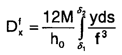
En premier lieu, on définit une spirale d'Archimède dans un repère (O, x, y) selon la formule, connue en soi :![]()
![]()
On donne à cette spirale une épaisseur de lame e0 dans le plan de la spirale et une hauteur de lame h0 perpendiculairement au plan de la spirale. Ces valeurs e0 et h0 sont constantes sur toute la longueur de la spirale.This spiral is given a blade thickness e 0 in the plane of the spiral and a blade height h 0 perpendicular to the plane of the spiral. These values e 0 and h 0 are constant over the entire length of the spiral.
On calcule les coordonnées (xG, yG) du centre de gravité G du spiral ainsi obtenu :

En utilisant les relations :![]()
![]()
![]()


![]()
![]()
![]()
On déduit ensuite le balourd du spiral, calculé au centre de gravité G :![]()
![]()
![]()
![]()
![]()
![]()
![]()
![]()
Puis l'on va déterminer une portion de spire extérieure à rendre inactive pour que ce balourd
Pour annuler le balourd
En assimilant cette portion de spire extérieure à un arc de cercle de rayon moyen (rayon à mi-épaisseur) Re, de centre O et de masse Δm, le module de son balourd ![]()

![]()

![]()
![]()
![]()
![]()
![]()
![]()
On renforce ensuite la section de la portion de spire extérieure délimitée par les angles β1 et β2 en donnant à cette portion de spire extérieure une épaisseur e, dans le plan du spiral, supérieure à l'épaisseur e0, par exemple égale à trois fois l'épaisseur e0. La
De préférence, afin d'éviter, ou à tout le moins réduire le risque, que le spiral se casse lors de sa fabrication ou de son fonctionnement au niveau des extrémités droites, orientées radialement, 12 de la portion rigidifiée 8", on corrige la forme de la portion rigidifiée 8" pour adoucir la transition entre cette dernière et le reste de la lame. Cette correction de forme de la portion rigidifiée 8" est typiquement effectuée de la manière suivante :Preferably, in order to avoid, or at least reduce the risk, that the hairspring breaks during its manufacture or operation at the radially oriented straight ends 12 of the stiffened
Dans un premier temps, on choisit une fonction f = e(ϑ) représentative de l'épaisseur, dans le plan du spiral, de la portion rigidifiée corrigée en fonction de l'angle polaire ϑ. Cette fonction f est convexe et continue, et présente un minimum, égal à l'épaisseur e0, aux deux extrémités de la portion rigidifiée.Firstly, a function f = e (θ) representative of the thickness, in the plane of the spiral, of the stiffened portion corrected as a function of the polar angle θ is chosen. This function f is convex and continuous, and has a minimum, equal to the thickness e 0 , at both ends of the stiffened portion.
Puis l'on calcule l'étendue angulaire δ2 - δ1 de cette portion rigidifiée corrigée. Cette étendue angulaire δ2 - δ1 inclut l'étendue angulaire β2 - β1 de la portion rigidifiée 8" illustrée à la
Pour déterminer les angles δ1 et δ2, on part du principe que la portion rigidifiée corrigée doit se déformer de la même manière que la portion de spire délimitée par ces angles δ1 et δ2 dans le spiral de la 
![]()
![]()

![]()
![]()
Pour résoudre l'équation ci-dessus, on peut effectuer un calcul itératif, en partant d'une valeur ϕ donnée, suffisamment grande par rapport à la longueur de la portion rigidifiée 8", puis en diminuant pas à pas cette valeur ϕ jusqu'à ce que les deux composantes de déformation ![]()
![]()
![]()

![]()
![]()
![]()
Une fois la valeur ϕ finale déterminée, on redessine la portion rigidifiée en lui donnant, entre les angles δ1 et δ2, l'épaisseur variable e(ϑ) = f.Once the final value φ is determined, the stiffened portion is redrawn by giving it, between the angles δ 1 and δ 2 , the variable thickness e (θ) = f.
On donne ci-dessous, à titre d'exemple, une fonction f convenant particulièrement pour l'épaisseur variable de la portion rigidifiée corrigée :
L'homme du métier observera toutefois que d'autres fonctions f convexes peuvent également convenir. La
On notera qu'ainsi corrigée, au moyen de l'une ou l'autre des fonctions mentionnées ci-dessus, la portion rigidifiée présente l'avantage non seulement de réduire le risque de rupture du spiral, mais également de présenter une rigidité supérieure à celle de la portion rigidifiée 8" illustrée à la
Une fois la correction de la portion rigidifiée effectuée, on simule, par exemple par un calcul d'éléments finis, une expansion maximale du spiral, correspondant à l'angle de rotation maximal du balancier, et l'on corrige la forme de la partie terminale de la spire extérieure de sorte que cette partie terminale soit suffisamment éloignée de l'avant-dernière spire pour que, comme expliqué précédemment, ni cette partie terminale ni ses éléments accessoires (piton, goupilles de raquette) ne puissent gêner les expansions de l'avant-dernière spire. Cette correction de la forme de la partie terminale est toutefois suffisamment faible pour ne pas modifier sensiblement le balourd du spiral et de la portion rigidifiée. La
Pour éloigner la partie terminale de la spire extérieure de l'avant-dernière spire, on peut procéder de la façon suivante (cf.
- On définit sur l'axe radial passant par l'extrémité extérieure du spiral un premier point P1 situé au-delà de l'avant-dernière spire lorsque le spiral est en expansion maximale, c'est-à-dire lorsque le balancier atteint son angle de rotation maximal (on se place, pour cela, dans une situation théorique où l'avant-dernière spire n'est pas gênée radialement et est donc en expansion maximale, comme dans l'exemple de la
figure 13 ), et à une distance de cette avant-dernière spire, également lorsque le spiral est en expansion maximale, par exemple d'environ un pas de spirale. Sur lafigure 14 , la position de l'extrémité extérieure du spiral est désignée par le repère P0 et la position du point d'intersection entre l'avant-dernière spire et l'axe radial précité lorsque le spiral est en expansion maximale est désignée par le repère P' (cette position P' est également représentée à lafigure 13 ). - On définit un second point P2, situé sur la spire extérieure à l'extrémité de la portion rigidifiée la plus éloignée de l'extrémité extérieure du spiral.
- On raccorde les premier et second points P1, P2 par un arc de cercle 18 tangent à la spire extérieure au niveau du second point P2. Le centre de cet arc de cercle 18 est désigné à la
figure 14 par le repère O". - On définit un troisième point P3 sur l'arc de cercle 18 entre les premier et second points P1, P2, ce troisième point P3 étant tel que la longueur du segment de l'arc de cercle 18 délimité par les second et troisième points P2, P3 soit égale à la longueur du segment de spire initial 19 délimité par le second point P2 et l'extrémité extérieure initiale P0 du spiral.
- On définit dans un repère de centre 0" dont les axes sont parallèles au repère (O, x, y), deux angles T1, T2. L'angle T2 est l'angle que fait le segment de droite [O", P2] avec l'axe des abscisses du repère de centre O". L'angle T1 est tel que la longueur de la portion de l'arc de cercle 18 délimitée par les angles T1 et T2 soit égale à la longueur de la portion du segment de spire initial 19 délimitée, dans le repère (O, x, y), par les angles δ1 et δ2.
- On donne à l'arc de cercle 18, entre les second et troisième points P2, P3, une épaisseur identique à celle du segment de spire initial 19. Cette épaisseur est donc variable entre les angles T1 et T2 et constante ailleurs. La fonction fc = e(ϑ") définissant ladite épaisseur variable entre les angles T1 et T2 en fonction de l'angle polaire ϑ" dans le repère précité de centre O", est obtenue en remplaçant dans la fonction f définissant l'épaisseur variable de la portion du segment de spire initial 19 délimitée par les angles δ1 et δ2, les paramètres βG, δ1 et δ2 par, respectivement, ϑ0", T1 et T2, où ϑ0"=(T1 +T2)/2. Ainsi, par exemple, dans le cas d'une fonction f égale à


- Le segment de spire délimité par les second et troisième points P2, P3 constitue alors la partie terminale corrigée de la spire extérieure.
- The radial axis passing through the outer end of the hairspring is defined by a first point P 1 located beyond the penultimate turn when the hairspring is in maximum expansion, that is to say when the balance reaches its maximum angle of rotation (it is placed, for this, in a theoretical situation where the penultimate turn is not hindered radially and is therefore in maximum expansion, as in the example of the
figure 13 ), and at a distance from this penultimate turn, also when the hairspring is in maximum expansion, for example about one spiral pitch. On thefigure 14 the position of the outer end of the hairspring is indicated by the reference P 0 and the position of the point of intersection between the penultimate turn and the aforementioned radial axis when the hairspring is in maximum expansion is indicated by the reference P '(this position P' is also represented atfigure 13 ). - A second point P 2 is defined, located on the outer turn at the end of the stiffened portion furthest from the outer end of the hairspring.
- The first and second points P 1 , P 2 are connected by an
arc 18 tangential to the outer turn at the second point P 2 . The center of thisarc 18 is designated at thefigure 14 by the mark O ". - A third point P 3 is defined on the
arc 18 between the first and second points P 1 , P 2 , this third point P 3 being such that the length of the segment of thecircular arc 18 delimited by the second and second third points P 2 , P 3 is equal to the length of theinitial turn segment 19 delimited by the second point P 2 and the initial outer end P 0 of the hairspring. - We define in a center coordinate system 0 "whose axes are parallel to the coordinate system (O, x, y), two angles T 1 , T 2. The angle T 2 is the angle that the line segment [O" , P 2 ] with the abscissa axis of the center mark O ". The angle T 1 is such that the length of the portion of the
circular arc 18 delimited by the angles T 1 and T 2 is equal to the length of the portion of theinitial turn segment 19 delimited, in the coordinate system (O, x, y), by the angles δ 1 and δ 2 . - Is given to the
arc 18, between the second and third points P 2 , P 3 , a thickness identical to that of theinitial turn segment 19. This thickness is variable between the angles T 1 and T 2 and constant elsewhere . The function fc = e (θ ") defining said variable thickness between the angles T 1 and T 2 as a function of the polar angle θ" in the reference said center O ", is obtained by replacing in the function f defining the variable thickness of the portion of theinitial turn segment 19 delimited by the angles δ 1 and δ 2 , the parameters β G , δ 1 and δ 2 by, respectively, θ 0 ", T 1 and T 2 , where θ 0 " = (T 1 + T 2 ) / 2 Thus, for example, in the case of a function f equal to - The turn segment delimited by the second and third points P 2 , P 3 then constitutes the corrected end portion of the outer turn.
En variante, afin d'obtenir le spiral illustré à la
- On définit un point sur la spire extérieure dans la portion rigidifiée, typiquement au centre de cette dernière.
- On décale radialement vers l'extérieur la partie terminale du spiral s'étendant depuis ledit point, en donnant au côté intérieur de cette partie terminale une forme en arc de cercle de centre 0 et au côté extérieur de cette partie terminale une forme donnant à cette partie terminale la même épaisseur que celle de la partie terminale initiale correspondante. Cette épaisseur est ainsi variable entre ledit point et l'angle δ1 et constante entre l'angle δ1 et l'extrémité extérieure du spiral. L'écart radial entre cette partie terminale et l'avant-dernière spire est choisi suffisamment grand pour que cette dernière ne puisse atteindre ladite partie terminale même lorsque le spiral est en expansion maximum.
- On raccorde la partie terminale précitée avec le reste de la portion rigidifiée par une portion droite de façon à former le
double coude 11. Cette portion droite a une épaisseur suffisamment grande pour ne pas diminuer la rigidité de la portion rigidifiée, par exemple égale à trois fois l'épaisseur e0 de la partie du spiral autre que la portion rigidifiée.
- A point is defined on the outer turn in the stiffened portion, typically in the center of the latter.
- The end portion of the hairspring extending from said point is radially outwardly shifted, giving to the inner side of this end portion an arcuate shape of center 0 and the outer side of this end portion a shape giving this end portion the same thickness as that of the corresponding initial terminal part. This thickness is thus variable between said point and the angle δ 1 and constant between the angle δ 1 and the outer end of the hairspring. The radial distance between this end portion and the penultimate turn is chosen so large that it can not reach said end portion even when the hairspring is in maximum expansion.
- The aforementioned end portion is connected with the rest of the stiffened portion by a straight portion so as to form the
double elbow 11. This straight portion has a thickness sufficiently large not to reduce the rigidity of the stiffened portion, for example equal to three times the thickness e 0 of the part of the spiral other than the stiffened portion.
Le spiral de l'organe de régulation selon l'invention est typiquement réalisé en silicium. Sa fabrication peut être effectuée de différentes manières, par exemple selon la méthode décrite dans le document
La présente invention a été décrite ci-dessus à titre d'exemple uniquement. Il apparaîtra clairement à l'homme du métier que des modifications peuvent être faites sans sortir du cadre de l'invention comme définie par les revendications. En particulier, bien qu'il soit préférable que la portion rigidifiée soit formée par une augmentation de l'épaisseur de la lame formant le spiral dans le plan du spiral, on pourrait, en variante, augmenter la hauteur de la lame (c'est-à-dire l'épaisseur de la lame perpendiculairement au plan du spiral). Dans ce cas bien entendu, la hauteur de la lame devrait être augmentée de façon relativement importante pour obtenir une rigidité comparable à celle obtenue dans le cas d'une épaisseur variable dans le plan du spiral. Dans une autre variante, on pourrait faire varier à la fois l'épaisseur de la lame dans le plan du spiral et la hauteur de ladite lame.The present invention has been described above by way of example only. It will be apparent to those skilled in the art that modifications can be made without departing from the scope of the invention as defined by the claims. In particular, although it is preferable that the stiffened portion is formed by an increase in the thickness of the blade forming the hairspring in the plane of the hairspring, one could, alternatively, increase the height of the blade (this is that is, the thickness of the blade perpendicular to the plane of the hairspring). In this case of course, the height of the blade should be increased relatively large to obtain a stiffness comparable to that obtained in the case of a variable thickness in the plane of the spiral. In another variant, one could vary both the thickness of the blade in the plane of the spiral and the height of said blade.
Claims (22)
- A timepiece movement comprising a regulating device comprising a balance (1) and a plane hairspring (2), the plane hairspring (2) comprising on its outer turn (7) a stiffened portion (8) arranged to cause the deformations of the turns to be substantially concentric, this stiffened portion (8) ending before the outer end (5) of the hairspring (2), the spacing between this stiffened portion (8) and the last-but-one turn (9) of the hairspring (2) increasing continuously in the direction of winding from the inside to the outside of the hairspring (2), characterised in that the spacing (d) between a terminal portion of the outer turn (7) and the last-but-one turn (9) of the hairspring (2) is large enough for said last-but-one turn (9) to remain free radially during expansions of the hairspring (2) up to amplitudes corresponding substantially to the maximum angle of rotation of the balance (1) in said movement.
- A timepiece movement according to claim 1, characterised in that the maximum angle of rotation of the balance (1) in said movement is slightly less than the knocking angle.
- A timepiece movement according to claim 1 or 2, characterised in that the maximum angle of rotation of the balance (1) in said movement is substantially equal to 330°.
- A timepiece movement according to any one of claims 1 to 3, characterised in that the spacing (d) between the terminal portion of the outer turn (7) and the last-but-one turn (9) of the hairspring (2) is large enough for said last-but-one turn (9) to remain free radially during expansions of the hairspring (2) up to amplitudes corresponding substantially to the knocking angle of the balance (1) in said movement.
- A timepiece movement according to any one of claims 1 to 4, characterised in that the stiffened portion (8) is a portion of strip of thickness (e) in the plane of the hairspring (2) greater than the thickness (e0) of the remainder of the strip forming the hairspring (2).
- A timepiece movement according to claim 5, characterised in that the thickness (e), in the plane of the hairspring (2), of the stiffened portion (8) varies over the length of the stiffened portion (8) as a convex function.
- A timepiece movement according to claim 6, characterised in that the thickness (e), in the plane of the hairspring (2), of the stiffened portion (8) varies over the length of the stiffened portion (8) as a convex and continuous function and presents a minimum substantially equal to the thickness (e0) of the remainder of the strip at the two ends of the stiffened portion (8).
- A timepiece movement according to claim 7, characterised in that the thickness (e), in the plane of the hairspring (2), of the stiffened portion (8) varies over the entire length of the stiffened portion (8) as a convex and continuous function and presents a minimum substantially equal to the thickness (e0) of the remainder of the strip at the two ends of the stiffened portion (8) and a maximum that is greater than the thickness (e0) of the remainder of the strip between said two ends.
- A timepiece movement according to claim 5, characterised in that the thickness (e), in the plane of the hairspring, of the stiffened portion (8") is substantially constant over the entire length of said stiffened portion (8").
- A timepiece movement according to claim 6 or 7, characterised in that the thickness (e), in the plane of the hairspring (2), of the stiffened portion (8"') is substantially constant over the entire length of said stiffened portion (8"') except in terminal portions (13) where, respectively, the thickness (e) decreases continuously towards the ends (14) of said stiffened portion (8"').
- A timepiece movement according to any one of claims 5 to 10, characterised in that the extra thickness defined by the stiffened portion (8) relative to the remainder of the strip is situated exclusively on the outer side of the outer turn (7).
- A timepiece movement according to any one of claims 5 to 11, characterised in that the height of the hairspring is substantially constant over the entire length of said hairspring.
- A timepiece movement according to any one of claims 1 to 12, characterised in that the hairspring is made of silicium.
- A timepiece, such as a watch, comprising a timepiece movement according to any one of claims 1 to 13.
- A method of making a regulating device having a balance (1) and a plane hairspring (2) for a timepiece movement, in which method the hairspring (2) is made with a stiffened portion (8) on its outer turn (7) so as to cause the deformations of the turns to be substantially concentric, this stiffened portion (8) ending before the outer end (5) of the hairspring (2), the spacing between this stiffened portion (8) and the last-but-one turn (9) of the hairspring (2) increasing continuously in the direction of winding from the inside to the outside of the hairspring (2), characterised in that the hairspring (2) is also made with a spacing (d) between a terminal portion of the outer turn (7) and the last-but-one turn (9) of the hairspring (2) that is large enough for said last-but-one turn (9) to remain free radially during expansions of the hairspring (2) up to amplitudes corresponding substantially to the maximum angle of rotation of the balance (1) in said movement.
- A method according to claim 15, characterised in that in order to design the plane hairspring (2) with the stiffened portion (8"), the following steps are performed:· defining a plane hairspring of constant strip thickness,· determining the unbalance of said plane hairspring;· determining a portion of the outer turn of said plane hairspring having the same unbalance as the plane hairspring; and· stiffening said outer turn portion.
- A method according to claim 16, characterised in that the step of stiffening the outer turn portion consists in increasing its thickness (e) in the plane of the hairspring (2).
- A method according to claim 15, characterised in that in order to design the plane hairspring (2) with the stiffened portion (8), the following steps are performed:· defining a plane hairspring of constant strip section;· determining the unbalance of said plane hairspring;· determining a portion of the outer turn of said plane hairspring having the same unbalance as the plane hairspring; and· varying the thickness (e), in the plane of the hairspring, of the strip forming the hairspring between an angle δ1 and an angle δ2 such that δ1 < β1 and δ2 > β2' where β2 - β1 is the angular extent of said portion of the outer turn, the thickness being caused to vary in accordance with a predetermined function f presenting a minimum substantially equal to the thickness (e0) of the remainder of the strip at the angles δ1 and δ2, the function f and the angles δ1 and δ2 being selected so that the deformation of the turn portion delimited by the angles δ1 and δ2 is substantially the same as the deformation which would occur if the thickness of the strip between the angles δ1 and β1 and between the angles β2 and δ2 where the same as that of the remainder of the hairspring and if, between the angles β1 and β2, the stiffness of the outer turn were equal to a predetermined value, greater than that of the remainder of the strip.
- A method according to claim 18, characterised in that said predetermined value is infinite.
- A method according to claim 18 or 19, characterised in that the predetermined function f is convex and continuous.
- A method according to any one of claims 15 to 20, characterised in that in order to determine a spacing (d) that is sufficient between the terminal portion of the outer turn (7) and the last-but-one turn (9), the following steps are implemented:· defining a first point (P1) on the radial axis passing through the outer end (P0) of an initial plane hairspring having a stiffened portion (8), the first point (P1) being situated beyond the last-but-one turn of said initial plane hairspring when said last-but-one turn is expanded by an amplitude corresponding to the maximum angle of rotation of the balance;· defining a second point (P2) on the outer turn;· interconnnecting the first and second points (P1, P2) by a circular arc (18) that is tangential to the outer turn at the second point (P2);· defining a third point (P3) on the circular arc (18) between the first and second points (P1, P2), the third point (P3) being such that the length of the segment of the circular arc (18) delimited by the second and third points (P2, P3) is equal to the length of the initial turn segment (19) delimited by the second point (P2) and the initial outer end (P0) of the hairspring; and· giving a thickness in the plane of the hairspring to the circular arc (18) between the second and third points (P2, P3) that is identical to the thickness of the initial turn segment (19), the resulting turn segment between the second and third points (P2, P3) constituting a corrected terminal portion of the outer turn.
- A method according to claim 21, characterised in that the second point (P2) is situated at the end of the stiffened portion that is further from the outer end of the hairspring.
Priority Applications (9)
| Application Number | Priority Date | Filing Date | Title |
|---|---|---|---|
| EP03009603A EP1473604B1 (en) | 2003-04-29 | 2003-04-29 | Balance and flat hairspring regulator for a watch movement |
| DE60333076T DE60333076D1 (en) | 2003-04-29 | 2003-04-29 | Balance and surface spiral spring regulator for movement |
| EP10004945A EP2224293B1 (en) | 2003-04-29 | 2003-04-29 | Balance and flat hairspring regulator for a watch movement |
| PCT/IB2004/001389 WO2004097534A1 (en) | 2003-04-29 | 2004-04-21 | Control member with a balance wheel and a planar spiral for a watch or clock movement |
| US10/554,296 US7344302B2 (en) | 2003-04-29 | 2004-04-21 | Control member with a balance wheel and a planar spiral for a watch or clock movement |
| JP2006506573A JP4763595B2 (en) | 2003-04-29 | 2004-04-21 | Adjustment device with balance wheel and flat spring for watch movement |
| CNB2004800113837A CN100465820C (en) | 2003-04-29 | 2004-04-21 | The regulating device that comprises escapement and plane hairspring that is used for watch and clock movement |
| TW093111255A TWI370335B (en) | 2003-04-29 | 2004-04-22 | Timepiece movement,time piece ,method of designing a timepiece movement,and method of making a regulating device for a timepiece movement |
| HK04109702.6A HK1066876A1 (en) | 2003-04-29 | 2004-12-08 | Balance and flat hairspring regulator for a watch movement |
Applications Claiming Priority (1)
| Application Number | Priority Date | Filing Date | Title |
|---|---|---|---|
| EP03009603A EP1473604B1 (en) | 2003-04-29 | 2003-04-29 | Balance and flat hairspring regulator for a watch movement |
Related Child Applications (1)
| Application Number | Title | Priority Date | Filing Date |
|---|---|---|---|
| EP10004945.1 Division-Into | 2010-05-11 |
Publications (2)
| Publication Number | Publication Date |
|---|---|
| EP1473604A1 EP1473604A1 (en) | 2004-11-03 |
| EP1473604B1 true EP1473604B1 (en) | 2010-06-23 |
Family
ID=32981768
Family Applications (2)
| Application Number | Title | Priority Date | Filing Date |
|---|---|---|---|
| EP03009603A Expired - Lifetime EP1473604B1 (en) | 2003-04-29 | 2003-04-29 | Balance and flat hairspring regulator for a watch movement |
| EP10004945A Expired - Lifetime EP2224293B1 (en) | 2003-04-29 | 2003-04-29 | Balance and flat hairspring regulator for a watch movement |
Family Applications After (1)
| Application Number | Title | Priority Date | Filing Date |
|---|---|---|---|
| EP10004945A Expired - Lifetime EP2224293B1 (en) | 2003-04-29 | 2003-04-29 | Balance and flat hairspring regulator for a watch movement |
Country Status (8)
| Country | Link |
|---|---|
| US (1) | US7344302B2 (en) |
| EP (2) | EP1473604B1 (en) |
| JP (1) | JP4763595B2 (en) |
| CN (1) | CN100465820C (en) |
| DE (1) | DE60333076D1 (en) |
| HK (1) | HK1066876A1 (en) |
| TW (1) | TWI370335B (en) |
| WO (1) | WO2004097534A1 (en) |
Cited By (1)
| Publication number | Priority date | Publication date | Assignee | Title |
|---|---|---|---|---|
| WO2015198261A1 (en) | 2014-06-26 | 2015-12-30 | Damasko Uhrenmanufaktur KG | Method for the production of a spiral hairspring for mechanical movements, and spiral hairspring |
Families Citing this family (42)
| Publication number | Priority date | Publication date | Assignee | Title |
|---|---|---|---|---|
| EP1605323A3 (en) * | 2004-04-13 | 2006-07-12 | Coredem S.A. | Spiral spring for mechanical clockwork |
| EP2104007A1 (en) * | 2008-03-20 | 2009-09-23 | Nivarox-FAR S.A. | Single-body spiral made from a silicon-based material and manufacturing method |
| ATE474250T1 (en) * | 2008-03-20 | 2010-07-15 | Nivarox Sa | MONOBLOCK DOUBLE SPIRAL AND ITS PRODUCTION PROCESS |
| EP2104008A1 (en) * | 2008-03-20 | 2009-09-23 | Nivarox-FAR S.A. | Single-body regulating organ and method for manufacturing same |
| EP2105807B1 (en) * | 2008-03-28 | 2015-12-02 | Montres Breguet SA | Monobloc elevated curve spiral and method for manufacturing same |
| EP2138912B1 (en) | 2008-06-24 | 2012-07-04 | Michel Belot | Horological hairspring with concentric development |
| EP2284629A1 (en) * | 2009-08-13 | 2011-02-16 | ETA SA Manufacture Horlogère Suisse | Thermocompensated mechanical resonator |
| CH701783B1 (en) * | 2009-09-07 | 2015-01-30 | Manuf Et Fabrique De Montres Et Chronomètres Ulysse Nardin Le Locle S A | spiral spring watch movement. |
| CH701846B8 (en) | 2009-09-21 | 2015-06-15 | Rolex Sa | Flat spiral for clockwork pendulum and balance-sprung assembly. |
| CH702062B1 (en) * | 2009-10-26 | 2022-01-31 | Mft Dhorlogerie Audemars Piguet Sa | Regulating organ comprising at least two pendulums, a watch movement as well as a timepiece comprising such an organ. |
| EP2337221A1 (en) * | 2009-12-15 | 2011-06-22 | The Swatch Group Research and Development Ltd. | Resonator thermocompensated at least to the first and second orders |
| EP2434353B1 (en) * | 2010-09-28 | 2018-01-10 | Montres Breguet SA | Anti-tripping hairspring for timepiece escapement |
| EP2466397B1 (en) * | 2010-12-20 | 2013-08-21 | Blancpain S.A. | Rotating clock component with peripheral guide |
| CH705234B1 (en) | 2011-07-14 | 2017-10-13 | Breitling Montres Sa | Method of manufacturing a spiral. |
| CH705471B1 (en) | 2011-09-07 | 2016-03-31 | Patek Philippe Sa Geneve | clockwork spring balance. |
| EP2570871B1 (en) * | 2011-09-14 | 2014-03-19 | Montres Breguet SA | Hairspring with two spiral springs |
| US8777195B2 (en) * | 2011-09-23 | 2014-07-15 | Adicep Technologies, Inc. | Non-linear torsion spring assembly |
| DE102012100817B4 (en) * | 2012-01-13 | 2014-04-03 | Christoph Damasko | Method for setting a vibration system for mechanical movements, oscillating system and mechanical clock |
| EP2864844B1 (en) * | 2012-06-26 | 2020-09-02 | Rolex Sa | Method for determining an unbalance feature of an oscillator |
| US9658598B2 (en) | 2012-07-17 | 2017-05-23 | Master Dynamic Limited | Hairspring for a time piece and hairspring design for concentricity |
| EP2728423A1 (en) * | 2012-11-06 | 2014-05-07 | Nivarox-FAR S.A. | Clockwork balance wheel-hairspring assembly |
| CH707165B1 (en) | 2012-11-07 | 2016-12-30 | Patek Philippe Sa Geneve | Watch movement with sprung balance. |
| HK1186057A2 (en) * | 2013-01-14 | 2014-03-07 | Master Dynamic Ltd | Stress-relief elastic structure of hairspring collet |
| CH707815B1 (en) * | 2013-03-19 | 2017-05-31 | Nivarox Far Sa | Subassembly of a clockwork escapement mechanism comprising a spiral spring. |
| EP2781965B1 (en) * | 2013-03-19 | 2017-11-15 | Nivarox-FAR S.A. | Frame for a clockwork |
| EP2781970B1 (en) * | 2013-03-19 | 2016-03-16 | Nivarox-FAR S.A. | Mechanism for adjusting a timepice hairspring |
| CH707811A2 (en) * | 2013-03-19 | 2014-09-30 | Nivarox Sa | piece component dismantled clockwork. |
| CH708429A1 (en) * | 2013-08-19 | 2015-02-27 | Manuf Et Fabrique De Montres Et Chronomètres Ulysse Nardin Le Locle S A | Spiral for a regulating member of a mechanical watch, a regulating member provided with such a hairspring, and method of making such a hairspring. |
| EP3159751B1 (en) | 2013-10-18 | 2018-10-03 | Montres Breguet SA | Flexible resilient hand |
| EP2980658B1 (en) * | 2014-08-01 | 2017-07-19 | Agenhor SA | Device for assembling and adjusting a hairspring |
| EP3023844B1 (en) * | 2014-11-20 | 2017-06-28 | Nivarox-FAR S.A. | Flexible ferrule |
| HK1209578A2 (en) | 2015-02-17 | 2016-04-01 | Master Dynamic Ltd | Silicon hairspring |
| US10474104B2 (en) | 2015-06-03 | 2019-11-12 | Eta Sa Manufacture Horlogere Suisse | Resonator with fine adjustment via an index-assembly |
| EP3159747A1 (en) * | 2015-10-22 | 2017-04-26 | ETA SA Manufacture Horlogère Suisse | Compact hairspring with constant cross-section |
| WO2017163148A1 (en) | 2016-03-23 | 2017-09-28 | Patek Philippe Sa Geneve | Balance wheel oscillator for timepiece |
| EP3629103B1 (en) * | 2018-09-28 | 2021-05-12 | The Swatch Group Research and Development Ltd | Timepiece comprising a mechanical movement of which the oscillation precision is regulated by an electronic device |
| FR3088396B1 (en) | 2018-11-08 | 2021-06-18 | Abdou Dib | ALMOST CONSTANT TORQUE SPIRAL SPRING FOR ENERGY STORAGE |
| EP3654111B1 (en) | 2018-11-15 | 2022-02-16 | Nivarox-FAR S.A. | Method for measuring the torque of a clock hairspring and device for such method of measurement |
| EP3667433B1 (en) * | 2018-12-12 | 2023-02-01 | Nivarox-FAR S.A. | Spring and method for manufacturing same |
| EP3913441B1 (en) | 2020-05-22 | 2024-05-01 | Patek Philippe SA Genève | Oscillator for a timepiece |
| EP4293428A1 (en) | 2022-06-14 | 2023-12-20 | Patek Philippe SA Genève | Hairspring for timepiece resonator |
| EP4372479A1 (en) * | 2022-11-18 | 2024-05-22 | Richemont International S.A. | Method for manufacturing timepiece hairsprings |
Family Cites Families (11)
| Publication number | Priority date | Publication date | Assignee | Title |
|---|---|---|---|---|
| BE526689A (en) * | ||||
| US209642A (en) * | 1878-11-05 | Improvement in balance-springs for time-keepers | ||
| GB697864A (en) * | 1951-03-22 | 1953-09-30 | Smith & Sons Ltd S | Improvements in or relating to hair springs |
| CH327796A (en) * | 1954-02-22 | 1958-02-15 | Horlogerie Suisse S A Asuag | Flat hairspring |
| US3154912A (en) * | 1963-01-22 | 1964-11-03 | Pinkas David | Means for mounting and regulating the outer end of a spiral spring |
| CH499094A (en) * | 1967-11-09 | 1970-11-15 | Kienzle Apparate Gmbh | Return spring for measuring devices |
| US3528237A (en) * | 1968-04-30 | 1970-09-15 | Timex Corp | Horological hairspring |
| CH1082672A4 (en) * | 1972-07-19 | 1975-03-14 | ||
| JPS5697646A (en) * | 1979-12-31 | 1981-08-06 | Nhk Spring Co Ltd | Reclining mechanism for seat |
| CH692532A5 (en) * | 1997-10-21 | 2002-07-15 | Ebauchesfabrik Eta Ag | A method of making a balance spring for a horological movement. |
| DE60206939T2 (en) * | 2002-11-25 | 2006-07-27 | Csem Centre Suisse D'electronique Et De Microtechnique S.A. | Spiral clockwork spring and process for its production |
-
2003
- 2003-04-29 EP EP03009603A patent/EP1473604B1/en not_active Expired - Lifetime
- 2003-04-29 DE DE60333076T patent/DE60333076D1/en not_active Expired - Lifetime
- 2003-04-29 EP EP10004945A patent/EP2224293B1/en not_active Expired - Lifetime
-
2004
- 2004-04-21 CN CNB2004800113837A patent/CN100465820C/en not_active Expired - Lifetime
- 2004-04-21 JP JP2006506573A patent/JP4763595B2/en not_active Expired - Lifetime
- 2004-04-21 WO PCT/IB2004/001389 patent/WO2004097534A1/en active Application Filing
- 2004-04-21 US US10/554,296 patent/US7344302B2/en active Active
- 2004-04-22 TW TW093111255A patent/TWI370335B/en active
- 2004-12-08 HK HK04109702.6A patent/HK1066876A1/en not_active IP Right Cessation
Cited By (2)
| Publication number | Priority date | Publication date | Assignee | Title |
|---|---|---|---|---|
| WO2015198261A1 (en) | 2014-06-26 | 2015-12-30 | Damasko Uhrenmanufaktur KG | Method for the production of a spiral hairspring for mechanical movements, and spiral hairspring |
| DE102014119737A1 (en) | 2014-06-26 | 2015-12-31 | Damasko Uhrenmanufaktur KG | Manufacturing method for a spiral spring for mechanical movements and spiral spring |
Also Published As
| Publication number | Publication date |
|---|---|
| CN100465820C (en) | 2009-03-04 |
| US20060262652A1 (en) | 2006-11-23 |
| EP1473604A1 (en) | 2004-11-03 |
| EP2224293B1 (en) | 2012-07-18 |
| CN1781060A (en) | 2006-05-31 |
| JP4763595B2 (en) | 2011-08-31 |
| EP2224293A2 (en) | 2010-09-01 |
| JP2006525504A (en) | 2006-11-09 |
| HK1066876A1 (en) | 2005-04-01 |
| DE60333076D1 (en) | 2010-08-05 |
| TWI370335B (en) | 2012-08-11 |
| WO2004097534A1 (en) | 2004-11-11 |
| US7344302B2 (en) | 2008-03-18 |
| TW200510972A (en) | 2005-03-16 |
| EP2224293A3 (en) | 2011-03-02 |
Similar Documents
| Publication | Publication Date | Title |
|---|---|---|
| EP1473604B1 (en) | Balance and flat hairspring regulator for a watch movement | |
| EP2917789B1 (en) | Pallet mechanism for a timepiece escapement | |
| EP2674817B1 (en) | Manufacturing method of an arbour of a timepiece barrel | |
| EP2290476B1 (en) | Isochronism corrector for a timepiece escapement and an escapement equipped with such a corrector | |
| EP2076821B1 (en) | Clockwork with constant-torque transmission between the power source and the mechanical oscillator | |
| CH710795A2 (en) | Silicon hairspring. | |
| EP2761380A2 (en) | Integral assembly of a hairspring and a collet | |
| EP3181940B2 (en) | Method for manufacturing a hairspring with a predetermined stiffness by localised removal of material | |
| EP2405313A1 (en) | Spiral with immobile mass centre | |
| EP2613206A1 (en) | Hairspring with two spiral springs with improved isochronism | |
| EP2917787B1 (en) | Clock movement having a balance and a hairspring | |
| EP2520984A1 (en) | Barrel comprising additional relilient means for the accumulation of energy | |
| EP2690506A1 (en) | Anti-tripping clock hairspring | |
| EP3598242A1 (en) | Cam timepiece mechanism | |
| CH713409A2 (en) | Spiral balance of the thermocompensated type, movement and timepiece. | |
| CH697207A5 (en) | Horological movement for timepiece i.e. watch, has control unit with spring, where space between end part and spring's turn is large so that penultimate turn is free when spiral expands till amplitude corresponding to maximum rotation angle | |
| CH706087A1 (en) | Flat spiral for integration in control element of movement in timepiece, has series of turns formed by rolled plate, where outer end portion of spiral includes series of stiffened zones separated by flexible zones | |
| EP2869138A2 (en) | Hairspring for a regulating member of a mechanical watch, regulating member provided with such a hairspring, and method for manufacturing such a hairspring | |
| CH717357A2 (en) | Watch hairspring in glass or ceramic, with complex geometry. | |
| EP2017681A1 (en) | Breguet overcoil for timepiece and method of manufacturing the same | |
| CH717283B1 (en) | Watch assembly comprising an oscillating element and an escapement. | |
| CH719658A2 (en) | Mechanical watch movement. | |
| WO2023214300A1 (en) | Regulating member for a timepiece movement | |
| EP4293428A1 (en) | Hairspring for timepiece resonator | |
| CH719140A1 (en) | Indexing device for a clock mechanism. |
Legal Events
| Date | Code | Title | Description |
|---|---|---|---|
| PUAI | Public reference made under article 153(3) epc to a published international application that has entered the european phase |
Free format text: ORIGINAL CODE: 0009012 |
|
| AK | Designated contracting states |
Kind code of ref document: A1 Designated state(s): AT BE BG CH CY CZ DE DK EE ES FI FR GB GR HU IE IT LI LU MC NL PT RO SE SI SK TR |
|
| AX | Request for extension of the european patent |
Extension state: AL LT LV MK |
|
| REG | Reference to a national code |
Ref country code: HK Ref legal event code: DE Ref document number: 1066876 Country of ref document: HK |
|
| 17P | Request for examination filed |
Effective date: 20050312 |
|
| AKX | Designation fees paid |
Designated state(s): CH DE FR GB IT LI |
|
| RAP1 | Party data changed (applicant data changed or rights of an application transferred) |
Owner name: PATEK, PHILIPPE SA |
|
| 17Q | First examination report despatched |
Effective date: 20081211 |
|
| RAP1 | Party data changed (applicant data changed or rights of an application transferred) |
Owner name: PATEK PHILIPPE SA GENEVE |
|
| GRAP | Despatch of communication of intention to grant a patent |
Free format text: ORIGINAL CODE: EPIDOSNIGR1 |
|
| GRAS | Grant fee paid |
Free format text: ORIGINAL CODE: EPIDOSNIGR3 |
|
| GRAA | (expected) grant |
Free format text: ORIGINAL CODE: 0009210 |
|
| AK | Designated contracting states |
Kind code of ref document: B1 Designated state(s): CH DE FR GB IT LI |
|
| REG | Reference to a national code |
Ref country code: CH Ref legal event code: EP |
|
| REF | Corresponds to: |
Ref document number: 60333076 Country of ref document: DE Date of ref document: 20100805 Kind code of ref document: P |
|
| REG | Reference to a national code |
Ref country code: CH Ref legal event code: NV Representative=s name: MICHELI & CIE SA |
|
| REG | Reference to a national code |
Ref country code: HK Ref legal event code: GR Ref document number: 1066876 Country of ref document: HK |
|
| PLBE | No opposition filed within time limit |
Free format text: ORIGINAL CODE: 0009261 |
|
| STAA | Information on the status of an ep patent application or granted ep patent |
Free format text: STATUS: NO OPPOSITION FILED WITHIN TIME LIMIT |
|
| 26N | No opposition filed |
Effective date: 20110324 |
|
| REG | Reference to a national code |
Ref country code: DE Ref legal event code: R097 Ref document number: 60333076 Country of ref document: DE Effective date: 20110323 |
|
| REG | Reference to a national code |
Ref country code: FR Ref legal event code: PLFP Year of fee payment: 14 |
|
| REG | Reference to a national code |
Ref country code: FR Ref legal event code: PLFP Year of fee payment: 15 |
|
| REG | Reference to a national code |
Ref country code: FR Ref legal event code: PLFP Year of fee payment: 16 |
|
| PGFP | Annual fee paid to national office [announced via postgrant information from national office to epo] |
Ref country code: IT Payment date: 20210310 Year of fee payment: 19 |
|
| PGFP | Annual fee paid to national office [announced via postgrant information from national office to epo] |
Ref country code: GB Payment date: 20220310 Year of fee payment: 20 Ref country code: CH Payment date: 20220314 Year of fee payment: 20 |
|
| PGFP | Annual fee paid to national office [announced via postgrant information from national office to epo] |
Ref country code: FR Payment date: 20220321 Year of fee payment: 20 |
|
| PGFP | Annual fee paid to national office [announced via postgrant information from national office to epo] |
Ref country code: DE Payment date: 20220309 Year of fee payment: 20 |
|
| REG | Reference to a national code |
Ref country code: DE Ref legal event code: R071 Ref document number: 60333076 Country of ref document: DE |
|
| REG | Reference to a national code |
Ref country code: CH Ref legal event code: PL |
|
| REG | Reference to a national code |
Ref country code: GB Ref legal event code: PE20 Expiry date: 20230428 |
|
| PG25 | Lapsed in a contracting state [announced via postgrant information from national office to epo] |
Ref country code: IT Free format text: LAPSE BECAUSE OF NON-PAYMENT OF DUE FEES Effective date: 20220429 |
|
| P01 | Opt-out of the competence of the unified patent court (upc) registered |
Effective date: 20230521 |
|
| PG25 | Lapsed in a contracting state [announced via postgrant information from national office to epo] |
Ref country code: GB Free format text: LAPSE BECAUSE OF EXPIRATION OF PROTECTION Effective date: 20230428 |