EP1473532B1 - Rotations-Trocknungsanlage - Google Patents
Rotations-Trocknungsanlage Download PDFInfo
- Publication number
- EP1473532B1 EP1473532B1 EP20040000427 EP04000427A EP1473532B1 EP 1473532 B1 EP1473532 B1 EP 1473532B1 EP 20040000427 EP20040000427 EP 20040000427 EP 04000427 A EP04000427 A EP 04000427A EP 1473532 B1 EP1473532 B1 EP 1473532B1
- Authority
- EP
- European Patent Office
- Prior art keywords
- processing drum
- drying plant
- housing
- rotary drying
- drum
- Prior art date
- Legal status (The legal status is an assumption and is not a legal conclusion. Google has not performed a legal analysis and makes no representation as to the accuracy of the status listed.)
- Expired - Lifetime
Links
- 238000001035 drying Methods 0.000 title claims description 20
- 238000010438 heat treatment Methods 0.000 claims description 10
- 238000007667 floating Methods 0.000 claims description 3
- 238000000605 extraction Methods 0.000 claims 3
- 238000003860 storage Methods 0.000 description 7
- 238000007789 sealing Methods 0.000 description 5
- 238000004140 cleaning Methods 0.000 description 3
- 238000003032 molecular docking Methods 0.000 description 3
- 238000005086 pumping Methods 0.000 description 3
- 230000003068 static effect Effects 0.000 description 3
- 230000004888 barrier function Effects 0.000 description 2
- 238000009833 condensation Methods 0.000 description 2
- 230000005494 condensation Effects 0.000 description 2
- 238000010276 construction Methods 0.000 description 2
- 238000000034 method Methods 0.000 description 2
- 230000000284 resting effect Effects 0.000 description 2
- 239000002033 PVDF binder Substances 0.000 description 1
- 239000000654 additive Substances 0.000 description 1
- 238000005452 bending Methods 0.000 description 1
- 230000015572 biosynthetic process Effects 0.000 description 1
- 238000006243 chemical reaction Methods 0.000 description 1
- 238000011109 contamination Methods 0.000 description 1
- 238000005260 corrosion Methods 0.000 description 1
- 230000007797 corrosion Effects 0.000 description 1
- 230000002349 favourable effect Effects 0.000 description 1
- 238000003754 machining Methods 0.000 description 1
- 238000012423 maintenance Methods 0.000 description 1
- 238000004519 manufacturing process Methods 0.000 description 1
- 239000000463 material Substances 0.000 description 1
- 238000002156 mixing Methods 0.000 description 1
- 238000005192 partition Methods 0.000 description 1
- 239000004810 polytetrafluoroethylene Substances 0.000 description 1
- 229920001343 polytetrafluoroethylene Polymers 0.000 description 1
- 229920002981 polyvinylidene fluoride Polymers 0.000 description 1
- XLYOFNOQVPJJNP-UHFFFAOYSA-N water Substances O XLYOFNOQVPJJNP-UHFFFAOYSA-N 0.000 description 1
Images


Classifications
-
- F—MECHANICAL ENGINEERING; LIGHTING; HEATING; WEAPONS; BLASTING
- F26—DRYING
- F26B—DRYING SOLID MATERIALS OR OBJECTS BY REMOVING LIQUID THEREFROM
- F26B11/00—Machines or apparatus for drying solid materials or objects with movement which is non-progressive
- F26B11/02—Machines or apparatus for drying solid materials or objects with movement which is non-progressive in moving drums or other mainly-closed receptacles
- F26B11/022—Arrangements of drives, bearings, supports
-
- F—MECHANICAL ENGINEERING; LIGHTING; HEATING; WEAPONS; BLASTING
- F26—DRYING
- F26B—DRYING SOLID MATERIALS OR OBJECTS BY REMOVING LIQUID THEREFROM
- F26B11/00—Machines or apparatus for drying solid materials or objects with movement which is non-progressive
- F26B11/02—Machines or apparatus for drying solid materials or objects with movement which is non-progressive in moving drums or other mainly-closed receptacles
- F26B11/04—Machines or apparatus for drying solid materials or objects with movement which is non-progressive in moving drums or other mainly-closed receptacles rotating about a horizontal or slightly-inclined axis
- F26B11/049—Machines or apparatus for drying solid materials or objects with movement which is non-progressive in moving drums or other mainly-closed receptacles rotating about a horizontal or slightly-inclined axis with provisions for working under increased or reduced pressure, with or without heating
Definitions
- the invention relates to a rotary drying system, in particular a vacuum dryer, comprising a mounted in a housing heated, rotatably driven, connected to operating media supply lines treatment drum with filling and emptying and a mounted in the treatment drum Brüdenabsaugstutzen, the treatment drum flying on a fixed axis is.
- a rotary dryer of this kind is by the FR-A-1 002 719 known.
- the electrically heated and subdivided by a partition into a product space and a suction chamber with suction provided therein treatment drum is arranged there on several concentrically nested tubes.
- a first, central vapor tube is adjoined outwardly by a second tube and then by a stationary hollow axle, on which a further tube designed as a hollow axis of rotation is mounted.
- the hollow axis of rotation terminates in the drum with a flange which is connected to a flange of the second tube.
- the fixed hollow shaft thus receives a rotating inner tube and is enclosed by a rotating outer tube fixed to the drum, namely the hollow axis of rotation.
- One from the EP-A2-0 315 041 known vacuum rotary dryer also has such a structure of several concentrically nested one another Tubes, wherein the drum is mounted on the outer, designed as a hollow rotary shaft tube.
- Such rotary dryers predominantly used in pharmacy and chemistry differ mainly in the geometric shape of the dryer or treatment drum and are e.g. known as double-cone dryers, tumble dryers, ball dryers and V or trousers dryers.
- These rotary dryers are compared to other dryers, e.g. Cone or Schneckentrocknem, the favorable drying time and the good cleaning ability, the complete emptying and the gentle treatment of the product together.
- They have a vacuum-resistant drum for receiving the product to be treated and a trained for heating with steam, water, thermal oil or the like double jacket.
- the drums are supported by two fixedly welded, co-rotating hollow pins in spherical roller bearings of housings, which are arranged on special bases on the left and right of the drum.
- the heating jacket of the drum is supplied with heating medium via a hollow pin, for which purpose a complex sealing head is necessary.
- a complex sealing head is necessary.
- special vapor pipes are inserted and fixed for sucking the vapors vaporized in the rotating dryer drum.
- This requires at least two dry storage, a special product seal and also a further seal against vacuum or the atmosphere.
- the vapor tubes are due to the necessary hardening in the sealing and storage area and the high demands to be complied with straightness and machining quality in the production very expensive and expensive.
- Another disadvantage is that, despite suitable base material for corrosion and, since they are not or only very difficult to heat, tend in their interior for condensation and caking of the product as well as to bending and twisting are claimed.
- the invention is therefore an object of the invention to provide a generic Rotatlons drying plant, which allows a simple, easy to dismantle construction and significantly improved operation In a pharma hygieneen execution, especially joints and gaps avoids the risk of contamination carryover as far as possible.
- the treatment drum is arranged on a rotatably driven, mounted on the fixed axis socket, wherein the fixed axis on the housing side arranged in a fixed bearing and at the same time is formed for Brüdenab Insert and mounted in the product space of the treatment drum to the fixed axis Comprising vapor suction, and wherein the socket is constructed as a rotary distributor for operating medium supply with sealed to the fixed axis annular chamber into which the axially inserted through the fixed axis operating media radially and / or exit.
- the drum only has to be sealed to the one housing, and there are no more co-rotating hollow pin required, as well as the number of bearings is reduced.
- the housing-side fixed bearing can be two static fixed bearings depending on the load or, in the case of a larger system, a static fixed bearing and a rotating bearing or a rotating bearing point.
- the rotatably driven, mounted on the fixed axis socket can consist of several parts screwed together and advantageously be welded into the treatment drum.
- the drive power e.g. via a connected to the socket, acted upon by a motor pinion gear, directly into the socket and thus introduced the drum.
- the formation of the fixed axis at the same time for vapor removal makes no further or additional component required for the storage of the rotating drum.
- the bushing By forming the bushing as a rotary distributor, all necessary connections, e.g. provide for a vacuum pumping station, a heating medium, electrical and air connections and connections for other process media, possibly with each forward and return, at a central location of the housing, namely at the distal end of the fixed axis of the drum, which also serves to evacuate the vapor.
- a vacuum pumping station e.g. a heating medium
- electrical and air connections and connections for other process media possibly with each forward and return
- the one-sided or on-the-fly storage of the treatment drum makes it possible in a simple manner to provide it with a follower disk towards the housing.
- the rotating disc with the treatment drum makes it possible to separate the working space from the sterile room.
- the disc can be advantageous to seal against a sterile wall of the housing.
- a narrow gap existing between the sterile wall and the disc can, in the resting state of the drum, be passed over e.g. a pneumatic seal can be locked.
- the housing is designed as a mobile, movable unit, for example provided with rollers.
- the rotary drying system according to the invention is thus as a compact unit during an entire process in all steps, without removing the product need to be used in different places.
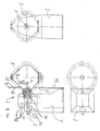
- FIGS. 1 to 3 shown rotary drying systems 1 - to the later versions of the Figures 2 and 3
- additional components which can not be quantified - which can be used not only for drying but also for storage, mixing, reaction processes in an inert or encapsulated atmosphere or under vacuum, all have a one-sided or floating on a fixed, in a housing 2 mounted on the axis 3, which is also designed for vapor removal, rotatably driven, formed in the embodiments in a double-cone design treatment drum 5.
- the treatment drum 5 has a double or heating jacket 6 and - dash-dotted lines - an insulating jacket 7 and inlet and / or discharge nozzle 8a, 8b indicated by arrows 9a, 9b docking devices, for example. Pneumatic bellows devices, for filling and / or emptying of or over barrels, special containers or the like.
- the optional treatment drum 5 to be equipped with a stirrer is freely accessible to an operator in every position of its stubs 8a, 8b.
- the treatment drum 5 is welded with a, on bearings 10 (see also FIG. 4 ) rotating, driven bushing 11 provided.
- a drive pinion 12 of an integrated motor in the housing 2 M with a fixedly connected to the bush 11 gear 13.
- the fixed axis 3, the housing side here in a static bearing 14 with also a rotating Bearing point 15 is mounted, has at its projecting into the drum interior end of a Brüdenabsaugstutzen 4 with a suction hood 16, while the other, free, emerging from the housing 2 end is designed as a docking device 17 to which a vacuum pump of a vacuum pump (not shown) can be connected.
- On the product side, ie to the treatment drum 5 towards the fixed axis 3 is sealed by means of a arranged in the rotating sleeve 11 mechanical seal 18.
- the bush 11 is formed with a rotary distributor 19.
- This has to supply the treatment drum 5 with a variety of operating media, indicated by dash-dotted lines 20 and flow arrows 21, according to the various existing connections, such as the vacuum pumping station, the flow and return of a heating medium, for the supply of a barrier medium (see. the dot-dash line 20a) to the mechanical seal 18, measuring lines for pressure, temperature or the like.
- a suitable sealing means 22 annular chambers 23rd on.
- co-rotating conduits 24 are guided through the gearwheel 13 through to the treatment drum 5.
- the storage of the treatment drum 5 on the rotating shaft 11 on the fixed axis 3 allows to provide all necessary connections at a central location of the housing 2, as in the FIGS. 1 to 3 indicated in the side views by the lines 20, axially forward by the fixed axis 3 and then via the rotary distributor 19, which can provide opposite flow paths.
- the rotary drying system 1 after FIG. 2 deviates from the above-described embodiment by a arranged on the treatment drum 5, rotating with this disc 25, which makes it possible to separate the working space from the sterile room.
- An existing between a sterile wall 26 and the disc 25 narrow gap can be locked in the resting state of the treatment drum 5 via a pneumatic seal 27 in the embodiment.
- FIGS. 1 and 2 stationary rotary drying units 1 can be converted in a simple manner into mobile units which can be used at any desired locations, as in FIG FIG. 3 shown. No matter in what version, so there is in any case before a variable rotary drying system in a simple, easy to disassemble and low maintenance construction.
- a variable speed control by hand or automatically, possible and a heating of the fixed axis, for example.
- a jacket heating counteracts condensation.
- the treatment drum can be positioned by hand or automatically in any desired position.
- parts eg a knife head as a tuber breaker, or a CIP (CLEAN IN PLACE) nozzle for cleaning and / or by over-rinsing under Rotation, the treatment drum can be further modified and adapted to the respective requirements.
- a corresponding filter bottom in the filling or emptying nozzle 8 a, 8 b enables, for example, the use as a pressure and / or vacuum suction filter.
Landscapes
- Engineering & Computer Science (AREA)
- Mechanical Engineering (AREA)
- General Engineering & Computer Science (AREA)
- Drying Of Solid Materials (AREA)
Description
- Die Erfindung betrifft eine Rotations-Trocknungsanlage, insbesondere Vakuumtrockner, umfassend eine in einem Gehäuse gelagerte beheizte, rotierend antreibbare, an Betriebsmedien-Versorgungsleitungen angeschlossene Behandlungstrommel mit Füll- und Entleereinrichtungen und einen in der Behandlungstrommel montierten Brüdenabsaugstutzen, wobei die Behandlungstrommel fliegend auf einer feststehenden Achse angeordnet ist.
- Ein Rotationstrockner dieser Art ist durch die
FR-A-1 002 719 - Ein aus der
EP-A2-0 315 041 bekannter Vakuum-Rotationstrockner besitzt ebenfalls einen derartigen Aufbau von mehreren konzentrisch ineinander geschachtelten Rohren, wobei die Trommel auf dem äußeren, als hohle Drehwelle ausgebildeten Rohr befestigt ist. - Solche überwiegend in der Pharmazie und Chemie eingesetzten RotationsTrockner unterscheiden sich in der Hauptsache durch die geometrische Form der Trockner- bzw. Behandlungstrommel und sind z.B. als Doppelkonus-Trockner, Taumel-Trockner, Kugel-Trockner und V- oder Hosen-Trockner bekannt. Diesen rotierenden Trocknern ist im Vergleich zu anderen Trocknern, z.B. Konus- bzw. Schneckentrocknem, die günstige Trocknungszeit sowie die gute Reinigungsmöglichkeit, die vollständige Restentleerung und die schonende Behandlung des Produktes gemeinsam. Sie besitzen eine vakuumfeste Trommel zur Aufnahme des zu behandelnden Produktes und einen zur Beheizung mit Dampf, Wasser, Thermoöl oder dergleichen ausgebildeten Doppelmantel. Die Trommeln lagern über zwei fest angeschweißte, mitrotierende Hohlzapfen in Pendelrollenlager von Gehäusen, die auf speziellen Fußgestellen links und rechts der Trommel angeordnet sind.
- Bei den bisher üblichen Trocknern wird über einen Hohlzapfen der Heizmantel der Trommel mit Heizmedium versorgt, wozu ein aufwändiger Dichtkopf notwendig ist. Durch den anderen Hohlzapfen werden zum Absaugen der in der rotierenden Trocknertrommel ausgedampften Brüden feststehende, spezielle Brüdenrohre gesteckt und fixiert. Das erfordert mindestens zwei Trockenlager, eine besondere Produktabdichtung und außerdem eine weitere Abdichtung gegen Vakuum bzw. die Atmosphäre. Die Brüdenrohre sind bedingt durch die notwendige Aufhärtung im Dicht- und Lagerbereich sowie die einzuhaltenden hohen Ansprüche auf Geradheit und Bearbeitungsqualität in der Herstellung sehr teuer und aufwändig. Nachteilig ist außerdem, dass sie trotz geeignetem Grundmaterial zur Korrosion und, da sie nicht oder nur sehr schwierig beheizbar sind, in ihrem Inneren zur Kondensation und Anbackungen des Produkts neigen sowie auch auf Biegung und Verdrehung beansprucht werden.
- Notwendige Rohrleitungen für Temperaturfühler, zur Einbringung von Zuschlagsstoffen oder dergleichen behindern den freien Querschnitt und verursachen in den Brüdenrohren Produktablagerungen. Gleichwohl ist eine Reinigung nicht möglich, und es lässt sich auch kein Inliner, belspw, aus PTFE oder PVDF, vorsehen. Abgesehen davon liegt ein besonderes Risiko für die Produktsicherheit In den unkontrollierbaren Räumen zwischen Brüdenrohr und Hohlzapfen. Zum Ziehen und Montieren der Brüdenrohre muß ein erheblicher Freiraum eingeplant werden, wie ebenfalls die Aufstellung einer Sterilwand oder dergleichen kaum möglich ist. Durch die Lagerung der Trommel auf zwei Gehäuse-Gestellen wird der Bediener beim Befüllen und insbesondere beim Entleeren stark eingeschränkt. Aufgrund der unvermeidbaren Fugen und Spalte durch Lagerungen etc. lässt sich mit den bekannten Trocknern keine pharmagerechte Ausführung erreichen.
- Der Erfindung liegt daher die Aufgabe zugrunde, eine gattungsgemäße Rotatlons-Trocknungsanlage zu schaffen, die eine einfache, leicht demontierbare Bau- und deutlich verbesserte Betriebsweise In einer pharmagerechten Ausführung ermöglicht, Insbesondere Fugen und Spalte mit der Gefahr von Kontaminations-Verschleppungen weitestgehend vermeidet.
- Diese Aufgabe wird erfindungsgemäß dadurch gelöst, dass die Behandlungstrommel auf einer rotierend angetriebenen, auf der feststehenden Achse gelagerten Buchse angeordnet ist, wobei die feststehende Achse gehäuseseitig in einem Festlager angeordnet sowie gleichzeitig zur Brüdenabführung ausgebildet ist und einen im Produktraum der Behandlungstrommel an die feststehende Achse montierten Brüdenabsaugstutzen aufweist, und wobei die Buchse als Rotationsverteiler zur Betriebsmedienversorgung mit zu der feststehenden Achse abgedichteten Ringkammer ausgebindet ist, in die die axial durch die feststehende Achse eingeführten Betriebsmedien radial ein- und/oder austreten.
- Die Trommel muß nur noch zu dem einen Gehäuse hin abgedichtet werden, und es sind nicht mehr mitrotierende Hohlzapfen erforderlich, wie auch die Anzahl der Lager bzw. Lagerungen verringert ist. Das gehäuseseitige Festlager können belastungsabhängig zwei statische Festlager oder bei einer größeren Anlage ein statisches Festlager und ein rotierendes Lager bzw. ein rotierender Lagerpunkt sein.
- Die rotierend angetriebene, auf der feststehenden Achse gelagerte Buchse kann aus mehreren miteinander verschraubten Teilen bestehen und vorteilhaft in die Behandlungstrommel eingeschweißt werden. Während die Achse die durch das Trommelgewicht und die Rotationskräfte auftretenden Belastungen aufnimmt, wird die Antriebsleistung, z.B. über ein mit der Buchse verbundenes, von einem Motorritzel beaufschlagtes Zahnrad, direkt in die Buchse und damit die Trommel eingeleitet. Die Ausbildung der feststehenden Achse gleichzeitig zur Brüdenabführung macht für die Lagerung der rotierenden Trommel kein weiteres bzw. zusätzliches Bauteil erforderlich.
- Durch die Ausbildung der Buchse als Rotationsverteiler lassen sich alle notwendigen Anschlüsse, z.B. für einen Vakuum-Pumpstand, ein Heizmedium, Elektro- und Luftanschlüsse sowie Anschlüsse für weitere Prozeßmedien, ggf. jeweils mit Vor- und Rücklauf, an einer zentralen Stelle des Gehäuses vorsehen, nämlich an dem von der Trommel entfernten Ende der feststehenden Achse, die auch zur Brüdenabführung dient. Über den Rotationsverteiler lässt sich beispw, auch der vakuum- und produktberührten Gleitringdichtung der rotierenden Buchse ein Sperrmedium zuführen. Von dem Rotationsverteiler verlaufen mitrotierende Leitungen durch das Antriebszahnrad bis zur Behandlungstrommel.
- Zur nur noch einseitigen Abdichtung der Trommel lässt sich vorteilhaft eine die Buchse gegen das Innere der Behandlungstrommel abdichtende Gleitringdichtung vorsehen.
- Die einseitige bzw. fliegende Lagerung der Behandlungstrommel erlaubt es in einfacher Weise, diese zum Gehäuse hin mit einer mitlaufenden Scheibe zu versehen. Die mit der Behandlungstrommel rotierende Scheibe ermöglicht es, den Arbeitsraum vom Sterilraum zu trennen.
- Die Scheibe lässt sich hierzu vorteilhaft gegen eine Sterilwand des Gehäuses abdichten. Ein zwischen der Sterilwand und der Scheibe vorhandener enger Spalt kann im Ruhezustand der Trommel über z.B. eine pneumatische Dichtung gesperrt werden.
- Nach einem Vorschlag der Erfindung ist das Gehäuse als eine mobile, verfahrbare Einheit ausgebildet, z.B. mit Laufrollen versehen. Die erfindungsgemäße Rotations-Trocknungsanlage ist damit als eine kompakte Einheit während eines gesamten Verfahrensprozesses in allen Schritten, ohne das Produkt entnehmen zu müssen, an verschiedenen Orten einsetzbar. Außerdem ist es möglich, für eine Vielzahl solcher mobiler Rotationstrockner nur eine Zentrifuge, eine Andockvorrichtung für Befüllen und/oder Entleeren und nur eine stationäre Energiestation, z.B. Heizung und Vakuum-Pumpstand, vorzusehen.
- Weitere Merkmale und Einzelheiten der Erfindung ergeben sich aus den Ansprüchen und der nachfolgenden Beschreibung von in den Zeichnungen dargestellten Ausführungsbeispielen der Erfindung. Es zeigen:
- Figur 1
- eine Rotations-Trocknungsanlage in Vorder-, Seiten- und Draufsicht;
- Figur 2
- eine Rotations-Trocknungsanlage in den drei Ansichten nach
Figur 1 , demgegenüber noch ausgebildet mit einer Sterilwand; - Figur 3
- eine Rotations-Trocknungsanlage in den drei Ansichten nach
Figur 1 , ausgebildet als verfahrbare, mobile Einheit; und - Figur 4
- als Einzelheit der Rotations-Trocknungsanlagen nach den
Figuren 1 bis 3 in einem schematischen Halbschnitt das vordere Ende einer die Behandlungstrommel tragenden, feststehenden Achse. - Die in den
Figuren 1 bis 3 dargestellten Rotations-Trocknungsanlagen 1 - zu den späteren Ausführungen nach denFiguren 2 und3 werden dort nur die gegenüber der Ausführung nachFigur 1 zusätzlichen, übereinstimmende Bauteile jedoch nicht beziffert werden - , die nicht nur zum Trocknen, sondern auch zum Lagern, Mischen, für Reaktionsprozesse unter inerter bzw. abgekapselter Atmosphäre oder unter Vakuum eingesetzt werden können, besitzen sämtlich eine einseitig bzw. fliegend auf einer feststehenden, in einem Gehäuse 2 gelagerten Achse 3, die gleichzeitig zur Brüdenabführung ausgebildet ist, rotierend antreibbare, in den Ausführungsbeispielen in einer Doppelkonus-Bauweise ausgebildete Behandlungstrommel 5. Die Behandlungstrommel 5 besitzt einen Doppel- bzw. Heizmantel 6 und - strichpunktiert angedeutet - einen Isoliermantel 7 sowie Ein- und/oder Entleerungsstutzen 8a, 8b mit durch Pfeile 9a, 9b angedeuteten Andockvorrichtungen, beispw. pneumatische Faltenbalg-Einrichtungen, zum Befüllen und/oder Entleeren von bzw. über Fässern, speziellen Behältern oder dergleichen. Die optional mit einem Rührwerk auszurüstende Behandlungstrommel 5 ist in jeder Position ihrer Stutzen 8a, 8b für einen Bediener ungehindert zugänglich. - Die Behandlungstrommel 5 ist mit einer eingeschweißten, auf Lagern 10 (vgl. auch
Figur 4 ) rotierenden, angetriebenen Buchse 11 versehen. Zum rotierenden Antrieb der Buchse 11 und damit der Behandlungstrommel 5 kämmt ein Antriebsritzel 12 eines im Gehäuse 2 integrierten Motors M mit einem fest mit der Buchse 11 verbundenen Zahnrad 13. Die feststehende Achse 3, die hier gehäuseseitig in einem statischen Festlager 14 mit außerdem einem rotierenden Lagerpunkt 15 gelagert ist, weist an ihrem in das Trommelinnere hineinragenden Ende einen Brüdenabsaugstutzen 4 mit einer Absaughaube 16 auf, während das andere, freie, aus dem Gehäuse 2 heraustretende Ende als Andockvorrichtung 17 ausgebildet ist, an die sich eine Vakuumpumpe eines Vakuum-Pumpenstandes (nicht dargestellt) anschließen lässt. Auf der Produktseite, d.h. zur Behandlungstrommel 5 hin ist die feststehende Achse 3 mittels einer in der rotierenden Buchse 11 angeordneten Gleitringdichtung 18 abgedichtet. - Wie sich näher der
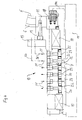
Figur 4 entnehmen lässt, ist die Buchse 11 mit einem Rotationsverteiler 19 ausgebildet. Dieser weist zur Versorgung der Behandlungstrommel 5 mit den verschiedensten Betriebsmedien, angedeutet durch strichpunktierte Linien 20 und Strömungspfeile 21, entsprechend den verschiedenen vorhandenen Anschlüssen, wie für den Vakuum-Pumpstand, den Vor- und Rücklauf eines Heizmediums, für die Zuführung eines Sperrmediums (vgl. die strichpunktierte Linie 20a) zu der Gleitringdichtung 18, Meßleitungen für Druck, Temperatur oder dergl., mehrere durch ein geeignetes Dichtmittel 22 abgedichtete Ringkammern 23 auf. Von diesen sind, wie inFigur 4 beispielhaft für die beiden dort vorderen Ringkammern 23 strichpunktiert angedeutet, mitrotierende Rohrleitungen 24 durch das Zahnrad 13 hindurch bis zur Behandlungstrommel 5 geführt. Die Lagerung der Behandlungstrommel 5 über die rotierende Buchse 11 auf der feststehenden Achse 3 erlaubt es, alle notwendigen Anschlüsse an einer zentralen Stelle des Gehäuses 2 vorzusehen, wie in denFiguren 1 bis 3 in den Seitenansichten durch die Linien 20 angedeutet, axial durch die feststehende Achse 3 und dann über den Rotationsverteiler 19 radial weiterzuleiten, wobei sich gegenläufige Strömungswege vorsehen lassen. - Die Rotations-Trocknungsanlage 1 nach
Figur 2 weicht von der vorbeschriebenen Ausführung durch eine auf der Behandlungstrommel 5 angeordnete, mit dieser rotierenden Scheibe 25 ab, die es ermöglicht, den Arbeitsraum vom Sterilraum zu trennen. Ein zwischen einer Sterilwand 26 und der Scheibe 25 vorhandener enger Spalt lässt sich im Ruhezustand der Behandlungstrommel 5 über eine im Ausführungsbeispiel pneumatische Dichtung 27 sperren. - Die nach den
Figuren 1 und2 stationären Rotations-Trocknungsanlagen 1 können dadurch, dass ihre Gehäuse 2 mit Laufrollen 28 versehen werden, in einfacher Weise zu mobilen, an beliebigen Orten einsetzbaren Einheiten umgerüstet werden, wie inFigur 3 dargestellt. Gleich in welcher Ausführung, so liegt doch in jedem Fall eine variable Rotations-Trocknungsanlage in einfacher, leicht demontierbarer und wartungsarmer Bauweise vor. - Im Betrieb ist eine variierbare Drehzahlregelung, von Hand oder automatisch, möglich und eine Beheizung der feststehenden Achse, beispw. durch eine Mantelbeheizung, wirkt einer Kondensation entgegen. Die Behandlungstrommel lässt sich von Hand oder automatisch in jede gewünschte Lage korrekt positionieren. Durch Anbauteile, z.B. eines Messerkopfes als Knollenbrecher, oder einer CIP(CLEAN IN PLACE)-Düse zum Reinigen und/oder durch Überspülen unter Rotation, kann die Behandlungstrommel weiter modifiziert und den jeweiligen Anforderungen angepasst werden. Ein entsprechender Filterboden im Einfüll- bzw. Entleerungsstutzen 8 a, 8 b ermöglicht beispw. auch den Einsatz als Druck-und/oder Vakuum-Nutsche.
Claims (6)
- Rotations-Trocknungsanlage (1), Insbesondere Vakuumtrockner, umfassend eine in einem Gehäuse (2) gelagerte beheizte, rotierend antreibbare, an Betriebsmedien-Versorgungsleitungen (20,21, 24) angeschlossene Behandlungstrommel (5) mit Füll- und Entleerungseinrichtungen (8a, 8b) und einen in der Behandlungstrommel (5) montierten Brüdenabsaugstutzen (4, 16), wobei die Behandlungstrommel (5) fliegend auf einer feststehenden Achse (3) angeordnet ist,
dadurch gekennzeichnet,
daß die Behandlungstrommel (5) auf einer rotierend angetriebenen, auf der feststehenden Achse (3) gelagerten Buchse (11) angeordnet Ist, wobei die feststehende Achse (3) gehäuseseitig in einem Festlager (14) angeordnet sowie gleichzeitig zur Brüdenabführung ausgebildet ist und einen Im Produktraum der Behandlungstrommel (5) an die feststehende Achse (3) montierten Brüdenabsaugstutzen (4) aufweist, und wobei die Buchse (11) als Rotationsverteiler (19) zur eine Heizmedienzufuhr einschlleßenden Betriebsmedienversorgung (20) mit zu der feststehenden Achse (3) abgedichteten Ringkammern (23) ausgebildet ist, in die die axial durch die feststehende Achse (3) eingeführten Betriebsmedien (20) radial ein- und/oder austreten. - Rotations-Trocknungsanlage nach Anspruch 1,
dadurch gekennzeichnet,
daß die Buchse (11) mit der Behandlungstrommel (5) verschweißt ist. - Rotations-Trockrungsanlage nach Anspruch 1 oder 2,
gekennzeichnet durch
eine die Buchse (11) gegen das Innere der Behandlungstrommel (5) abdichtende Gleitringdichtung (18). - Rotations-Trocknungsanlage nach einem der Ansprüche 1 bis 3,
dadurch gekennzeichnet,
daß die Behandlungstrommel (5) zum Gehäuse (2) hin mit einer mitlaufenden Scheibe (25) versehen ist. - Rotations-Trocknungsanlage nach Anspruch 4,
dadurch gekennzeichnet,
daß die Scheibe (25) gegen eine Sterilwand (28) des Gehäuses (2) abgedichtet ist. - Rotations-Trocknungsanlage nach einem der Ansprüche 1 bis 5,
dadurch gekennzeichnet,
daß das Gehäuse (2) als eine mobile, verfahrbare Einheit ausgebildet ist.
Applications Claiming Priority (2)
| Application Number | Priority Date | Filing Date | Title |
|---|---|---|---|
| DE10301030 | 2003-01-13 | ||
| DE10301030 | 2003-01-13 |
Publications (3)
| Publication Number | Publication Date |
|---|---|
| EP1473532A2 EP1473532A2 (de) | 2004-11-03 |
| EP1473532A3 EP1473532A3 (de) | 2008-08-20 |
| EP1473532B1 true EP1473532B1 (de) | 2013-03-13 |
Family
ID=32980539
Family Applications (1)
| Application Number | Title | Priority Date | Filing Date |
|---|---|---|---|
| EP20040000427 Expired - Lifetime EP1473532B1 (de) | 2003-01-13 | 2004-01-12 | Rotations-Trocknungsanlage |
Country Status (4)
| Country | Link |
|---|---|
| EP (1) | EP1473532B1 (de) |
| DE (1) | DE202004021648U1 (de) |
| DK (1) | DK1473532T3 (de) |
| ES (1) | ES2405289T3 (de) |
Families Citing this family (3)
| Publication number | Priority date | Publication date | Assignee | Title |
|---|---|---|---|---|
| DE102009027790B4 (de) * | 2009-04-08 | 2017-05-18 | Dorfner Analysenzentrum Und Anlagenplanungs-Gesellschaft Mbh | Vorrichtung und Verfahren zum Reinigen von Quarzmaterial oder Silicium |
| CN103954108A (zh) * | 2014-05-05 | 2014-07-30 | 杨元清 | 一种不锈钢干燥混合机 |
| CN117404882B (zh) * | 2023-12-15 | 2024-04-05 | 常州市步步干燥设备有限公司 | 一种双锥回转式真空干燥机 |
Family Cites Families (6)
| Publication number | Priority date | Publication date | Assignee | Title |
|---|---|---|---|---|
| FR1002719A (fr) | 1949-12-10 | 1952-03-10 | Perfectionnements aux séchoirs à vide | |
| GB774397A (en) * | 1954-04-23 | 1957-05-08 | Barronia Metals Great Britain | Improvements in or relating to grain driers |
| DE1079549B (de) * | 1958-12-17 | 1960-04-07 | Henkhaus Appbau Vacuumtechnik | Taumeltrockner mit Mantelheizung |
| GB1445941A (en) * | 1974-02-26 | 1976-08-11 | Apv Co Ltd | Heat treatment of particulate solid materials |
| DE3446424A1 (de) * | 1984-12-20 | 1986-06-26 | Glatt GmbH, 7851 Binzen | Waermestrahlungs-trockner |
| EP0315041B1 (de) | 1987-11-02 | 1993-03-17 | Fujisawa Pharmaceutical Co., Ltd. | Vakuum-Rotationstrockner |
-
2004
- 2004-01-12 DK DK04000427T patent/DK1473532T3/da active
- 2004-01-12 EP EP20040000427 patent/EP1473532B1/de not_active Expired - Lifetime
- 2004-01-12 DE DE202004021648U patent/DE202004021648U1/de not_active Expired - Lifetime
- 2004-01-12 ES ES04000427T patent/ES2405289T3/es not_active Expired - Lifetime
Also Published As
| Publication number | Publication date |
|---|---|
| ES2405289T3 (es) | 2013-05-30 |
| EP1473532A3 (de) | 2008-08-20 |
| EP1473532A2 (de) | 2004-11-03 |
| DK1473532T3 (da) | 2013-06-10 |
| DE202004021648U1 (de) | 2009-11-26 |
Similar Documents
| Publication | Publication Date | Title |
|---|---|---|
| DE2408839C2 (de) | Zweiwellen-Gasturbinentriebwerk | |
| EP0304925B1 (de) | Mischkneter mit Knetgabeln | |
| DE3503695A1 (de) | Pneumatik-achslager | |
| WO2002100512A1 (de) | Drehfilteranlage | |
| EP1078682A2 (de) | Mischkneter | |
| DE2054968A1 (de) | Filtrationsapparat | |
| DE2552231A1 (de) | Verfahren und vorrichtung zum entgasen viskoser fluessigkeiten | |
| DE3537822C2 (de) | ||
| WO2018087254A1 (de) | Exzenterschneckenpumpe | |
| DE69627701T2 (de) | Trocknungsvorrichtung mit drehbarem gehäuse | |
| EP2002874B1 (de) | Filtervorrichtung | |
| DE3622103C2 (de) | ||
| DE3533038C2 (de) | ||
| DE4009926A1 (de) | Mischtrockner bzw. vorrichtung zum be- und verarbeiten von fluessigen, pastoesen, feuchten und trockenen produkten | |
| EP1473532A2 (de) | Rotations-Trocknungsanlage | |
| DE1805704A1 (de) | Rotationstrocknungsvorrichtung | |
| DE102010018817A1 (de) | Transportvorrichtung für eine Maschine zur Herstellung von stabförmigen Produkten der Tabak verarbeitenden Industrie | |
| AT395872B (de) | Vorrichtung zum sieben einer zellulosefaserbrei-suspension | |
| EP2729228B1 (de) | Verfahren zum trennen von feststoffen und flüssigkeiten einer suspension | |
| DE3641952A1 (de) | Prozessfilter | |
| DE4303852A1 (de) | Mischkneter | |
| DE3818508C2 (de) | ||
| DE2807725C2 (de) | Vakuumtrockner, insbesondere zur Vortrocknung von Substanzen mit einem im Vergleich zur Flüssigkeit geringen Feststoffgehalt | |
| DE102021133580B3 (de) | Verfahren und Vorrichtung zum Herstellen einer elektrischen Maschine sowie eine elektrische Maschine | |
| DE944000C (de) | Kontinuierlich arbeitende Siebschleuder |
Legal Events
| Date | Code | Title | Description |
|---|---|---|---|
| PUAI | Public reference made under article 153(3) epc to a published international application that has entered the european phase |
Free format text: ORIGINAL CODE: 0009012 |
|
| AK | Designated contracting states |
Kind code of ref document: A2 Designated state(s): AT BE BG CH CY CZ DE DK EE ES FI FR GB GR HU IE IT LI LU MC NL PT RO SE SI SK TR |
|
| AX | Request for extension of the european patent |
Extension state: AL LT LV MK |
|
| PUAL | Search report despatched |
Free format text: ORIGINAL CODE: 0009013 |
|
| AK | Designated contracting states |
Kind code of ref document: A3 Designated state(s): AT BE BG CH CY CZ DE DK EE ES FI FR GB GR HU IE IT LI LU MC NL PT RO SE SI SK TR |
|
| AX | Request for extension of the european patent |
Extension state: AL LT LV MK |
|
| RIC1 | Information provided on ipc code assigned before grant |
Ipc: F26B 11/02 20060101ALI20080715BHEP Ipc: F26B 11/04 20060101AFI20040907BHEP |
|
| 17P | Request for examination filed |
Effective date: 20090131 |
|
| AKX | Designation fees paid |
Designated state(s): AT BE BG CH CY CZ DE DK EE ES FI FR GB GR HU IE IT LI LU MC NL PT RO SE SI SK TR |
|
| 17Q | First examination report despatched |
Effective date: 20090515 |
|
| RAP1 | Party data changed (applicant data changed or rights of an application transferred) |
Owner name: PINK GMBH THERMOSYSTEME |
|
| RIN1 | Information on inventor provided before grant (corrected) |
Inventor name: DREISBACH, BERND |
|
| GRAP | Despatch of communication of intention to grant a patent |
Free format text: ORIGINAL CODE: EPIDOSNIGR1 |
|
| GRAS | Grant fee paid |
Free format text: ORIGINAL CODE: EPIDOSNIGR3 |
|
| GRAA | (expected) grant |
Free format text: ORIGINAL CODE: 0009210 |
|
| AK | Designated contracting states |
Kind code of ref document: B1 Designated state(s): AT BE BG CH CY CZ DE DK EE ES FI FR GB GR HU IE IT LI LU MC NL PT RO SE SI SK TR |
|
| REG | Reference to a national code |
Ref country code: GB Ref legal event code: FG4D Free format text: NOT ENGLISH |
|
| REG | Reference to a national code |
Ref country code: CH Ref legal event code: EP Ref country code: AT Ref legal event code: REF Ref document number: 601041 Country of ref document: AT Kind code of ref document: T Effective date: 20130315 |
|
| REG | Reference to a national code |
Ref country code: IE Ref legal event code: FG4D Free format text: LANGUAGE OF EP DOCUMENT: GERMAN |
|
| REG | Reference to a national code |
Ref country code: CH Ref legal event code: NV Representative=s name: SCHMAUDER AND PARTNER AG PATENT- UND MARKENANW, CH |
|
| REG | Reference to a national code |
Ref country code: DE Ref legal event code: R096 Ref document number: 502004014059 Country of ref document: DE Effective date: 20130508 |
|
| REG | Reference to a national code |
Ref country code: ES Ref legal event code: FG2A Ref document number: 2405289 Country of ref document: ES Kind code of ref document: T3 Effective date: 20130530 |
|
| REG | Reference to a national code |
Ref country code: SE Ref legal event code: TRGR |
|
| REG | Reference to a national code |
Ref country code: DK Ref legal event code: T3 |
|
| PG25 | Lapsed in a contracting state [announced via postgrant information from national office to epo] |
Ref country code: BG Free format text: LAPSE BECAUSE OF FAILURE TO SUBMIT A TRANSLATION OF THE DESCRIPTION OR TO PAY THE FEE WITHIN THE PRESCRIBED TIME-LIMIT Effective date: 20130613 |
|
| REG | Reference to a national code |
Ref country code: NL Ref legal event code: T3 |
|
| PG25 | Lapsed in a contracting state [announced via postgrant information from national office to epo] |
Ref country code: SI Free format text: LAPSE BECAUSE OF FAILURE TO SUBMIT A TRANSLATION OF THE DESCRIPTION OR TO PAY THE FEE WITHIN THE PRESCRIBED TIME-LIMIT Effective date: 20130313 Ref country code: GR Free format text: LAPSE BECAUSE OF FAILURE TO SUBMIT A TRANSLATION OF THE DESCRIPTION OR TO PAY THE FEE WITHIN THE PRESCRIBED TIME-LIMIT Effective date: 20130614 |
|
| REG | Reference to a national code |
Ref country code: SK Ref legal event code: T3 Ref document number: E 14334 Country of ref document: SK |
|
| REG | Reference to a national code |
Ref country code: HU Ref legal event code: AG4A Ref document number: E016779 Country of ref document: HU |
|
| PG25 | Lapsed in a contracting state [announced via postgrant information from national office to epo] |
Ref country code: EE Free format text: LAPSE BECAUSE OF FAILURE TO SUBMIT A TRANSLATION OF THE DESCRIPTION OR TO PAY THE FEE WITHIN THE PRESCRIBED TIME-LIMIT Effective date: 20130313 Ref country code: RO Free format text: LAPSE BECAUSE OF FAILURE TO SUBMIT A TRANSLATION OF THE DESCRIPTION OR TO PAY THE FEE WITHIN THE PRESCRIBED TIME-LIMIT Effective date: 20130313 Ref country code: PT Free format text: LAPSE BECAUSE OF FAILURE TO SUBMIT A TRANSLATION OF THE DESCRIPTION OR TO PAY THE FEE WITHIN THE PRESCRIBED TIME-LIMIT Effective date: 20130715 |
|
| PG25 | Lapsed in a contracting state [announced via postgrant information from national office to epo] |
Ref country code: CY Free format text: LAPSE BECAUSE OF FAILURE TO SUBMIT A TRANSLATION OF THE DESCRIPTION OR TO PAY THE FEE WITHIN THE PRESCRIBED TIME-LIMIT Effective date: 20130313 |
|
| PLBE | No opposition filed within time limit |
Free format text: ORIGINAL CODE: 0009261 |
|
| STAA | Information on the status of an ep patent application or granted ep patent |
Free format text: STATUS: NO OPPOSITION FILED WITHIN TIME LIMIT |
|
| 26N | No opposition filed |
Effective date: 20131216 |
|
| REG | Reference to a national code |
Ref country code: DE Ref legal event code: R097 Ref document number: 502004014059 Country of ref document: DE Effective date: 20131216 |
|
| PG25 | Lapsed in a contracting state [announced via postgrant information from national office to epo] |
Ref country code: MC Free format text: LAPSE BECAUSE OF FAILURE TO SUBMIT A TRANSLATION OF THE DESCRIPTION OR TO PAY THE FEE WITHIN THE PRESCRIBED TIME-LIMIT Effective date: 20130313 |
|
| REG | Reference to a national code |
Ref country code: FR Ref legal event code: PLFP Year of fee payment: 12 |
|
| PGFP | Annual fee paid to national office [announced via postgrant information from national office to epo] |
Ref country code: LU Payment date: 20150122 Year of fee payment: 12 |
|
| PGFP | Annual fee paid to national office [announced via postgrant information from national office to epo] |
Ref country code: NL Payment date: 20150129 Year of fee payment: 12 |
|
| PGFP | Annual fee paid to national office [announced via postgrant information from national office to epo] |
Ref country code: SK Payment date: 20150112 Year of fee payment: 12 Ref country code: HU Payment date: 20150121 Year of fee payment: 12 Ref country code: CZ Payment date: 20150109 Year of fee payment: 12 Ref country code: DE Payment date: 20150121 Year of fee payment: 12 Ref country code: DK Payment date: 20150121 Year of fee payment: 12 Ref country code: IT Payment date: 20150126 Year of fee payment: 12 Ref country code: IE Payment date: 20150122 Year of fee payment: 12 Ref country code: CH Payment date: 20150121 Year of fee payment: 12 Ref country code: FI Payment date: 20150113 Year of fee payment: 12 Ref country code: ES Payment date: 20150128 Year of fee payment: 12 |
|
| PGFP | Annual fee paid to national office [announced via postgrant information from national office to epo] |
Ref country code: GB Payment date: 20150121 Year of fee payment: 12 Ref country code: SE Payment date: 20150121 Year of fee payment: 12 Ref country code: FR Payment date: 20150122 Year of fee payment: 12 Ref country code: AT Payment date: 20150122 Year of fee payment: 12 |
|
| PGFP | Annual fee paid to national office [announced via postgrant information from national office to epo] |
Ref country code: BE Payment date: 20150121 Year of fee payment: 12 |
|
| REG | Reference to a national code |
Ref country code: DE Ref legal event code: R082 Ref document number: 502004014059 Country of ref document: DE Representative=s name: STUMPF PATENTANWAELTE PARTGMBB, DE |
|
| PG25 | Lapsed in a contracting state [announced via postgrant information from national office to epo] |
Ref country code: BE Free format text: LAPSE BECAUSE OF NON-PAYMENT OF DUE FEES Effective date: 20160131 |
|
| PG25 | Lapsed in a contracting state [announced via postgrant information from national office to epo] |
Ref country code: TR Free format text: LAPSE BECAUSE OF FAILURE TO SUBMIT A TRANSLATION OF THE DESCRIPTION OR TO PAY THE FEE WITHIN THE PRESCRIBED TIME-LIMIT Effective date: 20130313 |
|
| REG | Reference to a national code |
Ref country code: DE Ref legal event code: R119 Ref document number: 502004014059 Country of ref document: DE |
|
| REG | Reference to a national code |
Ref country code: DK Ref legal event code: EBP Effective date: 20160131 |
|
| PG25 | Lapsed in a contracting state [announced via postgrant information from national office to epo] |
Ref country code: LU Free format text: LAPSE BECAUSE OF NON-PAYMENT OF DUE FEES Effective date: 20160112 |
|
| REG | Reference to a national code |
Ref country code: CH Ref legal event code: PL |
|
| REG | Reference to a national code |
Ref country code: AT Ref legal event code: MM01 Ref document number: 601041 Country of ref document: AT Kind code of ref document: T Effective date: 20160112 |
|
| GBPC | Gb: european patent ceased through non-payment of renewal fee |
Effective date: 20160112 |
|
| REG | Reference to a national code |
Ref country code: SK Ref legal event code: MM4A Ref document number: E 14334 Country of ref document: SK Effective date: 20160112 |
|
| REG | Reference to a national code |
Ref country code: NL Ref legal event code: MM Effective date: 20160201 |
|
| REG | Reference to a national code |
Ref country code: FR Ref legal event code: ST Effective date: 20160930 |
|
| PG25 | Lapsed in a contracting state [announced via postgrant information from national office to epo] |
Ref country code: DE Free format text: LAPSE BECAUSE OF NON-PAYMENT OF DUE FEES Effective date: 20160802 Ref country code: HU Free format text: LAPSE BECAUSE OF NON-PAYMENT OF DUE FEES Effective date: 20160113 Ref country code: FI Free format text: LAPSE BECAUSE OF NON-PAYMENT OF DUE FEES Effective date: 20160112 Ref country code: CH Free format text: LAPSE BECAUSE OF NON-PAYMENT OF DUE FEES Effective date: 20160131 Ref country code: GB Free format text: LAPSE BECAUSE OF NON-PAYMENT OF DUE FEES Effective date: 20160112 Ref country code: LI Free format text: LAPSE BECAUSE OF NON-PAYMENT OF DUE FEES Effective date: 20160131 |
|
| REG | Reference to a national code |
Ref country code: IE Ref legal event code: MM4A |
|
| PG25 | Lapsed in a contracting state [announced via postgrant information from national office to epo] |
Ref country code: AT Free format text: LAPSE BECAUSE OF NON-PAYMENT OF DUE FEES Effective date: 20160112 Ref country code: FR Free format text: LAPSE BECAUSE OF NON-PAYMENT OF DUE FEES Effective date: 20160201 Ref country code: NL Free format text: LAPSE BECAUSE OF NON-PAYMENT OF DUE FEES Effective date: 20160201 Ref country code: SE Free format text: LAPSE BECAUSE OF NON-PAYMENT OF DUE FEES Effective date: 20160113 Ref country code: CZ Free format text: LAPSE BECAUSE OF NON-PAYMENT OF DUE FEES Effective date: 20160112 Ref country code: SK Free format text: LAPSE BECAUSE OF NON-PAYMENT OF DUE FEES Effective date: 20160112 |
|
| PG25 | Lapsed in a contracting state [announced via postgrant information from national office to epo] |
Ref country code: IT Free format text: LAPSE BECAUSE OF NON-PAYMENT OF DUE FEES Effective date: 20160112 |
|
| PG25 | Lapsed in a contracting state [announced via postgrant information from national office to epo] |
Ref country code: IE Free format text: LAPSE BECAUSE OF NON-PAYMENT OF DUE FEES Effective date: 20160112 Ref country code: DK Free format text: LAPSE BECAUSE OF NON-PAYMENT OF DUE FEES Effective date: 20160131 |
|
| REG | Reference to a national code |
Ref country code: ES Ref legal event code: FD2A Effective date: 20170224 |
|
| PG25 | Lapsed in a contracting state [announced via postgrant information from national office to epo] |
Ref country code: ES Free format text: LAPSE BECAUSE OF NON-PAYMENT OF DUE FEES Effective date: 20160113 |