EP1473418A2 - Dichtungsband - Google Patents
Dichtungsband Download PDFInfo
- Publication number
- EP1473418A2 EP1473418A2 EP04000999A EP04000999A EP1473418A2 EP 1473418 A2 EP1473418 A2 EP 1473418A2 EP 04000999 A EP04000999 A EP 04000999A EP 04000999 A EP04000999 A EP 04000999A EP 1473418 A2 EP1473418 A2 EP 1473418A2
- Authority
- EP
- European Patent Office
- Prior art keywords
- sealing tape
- foam
- adhesive
- tape
- sealing
- Prior art date
- Legal status (The legal status is an assumption and is not a legal conclusion. Google has not performed a legal analysis and makes no representation as to the accuracy of the status listed.)
- Granted
Links
Images


Classifications
-
- E—FIXED CONSTRUCTIONS
- E04—BUILDING
- E04D—ROOF COVERINGS; SKY-LIGHTS; GUTTERS; ROOF-WORKING TOOLS
- E04D3/00—Roof covering by making use of flat or curved slabs or stiff sheets
- E04D3/38—Devices for sealing spaces or joints between roof-covering elements
-
- E—FIXED CONSTRUCTIONS
- E04—BUILDING
- E04B—GENERAL BUILDING CONSTRUCTIONS; WALLS, e.g. PARTITIONS; ROOFS; FLOORS; CEILINGS; INSULATION OR OTHER PROTECTION OF BUILDINGS
- E04B1/00—Constructions in general; Structures which are not restricted either to walls, e.g. partitions, or floors or ceilings or roofs
- E04B1/62—Insulation or other protection; Elements or use of specified material therefor
- E04B1/66—Sealings
- E04B1/68—Sealings of joints, e.g. expansion joints
- E04B1/6812—Compressable seals of solid form
-
- E—FIXED CONSTRUCTIONS
- E04—BUILDING
- E04D—ROOF COVERINGS; SKY-LIGHTS; GUTTERS; ROOF-WORKING TOOLS
- E04D3/00—Roof covering by making use of flat or curved slabs or stiff sheets
- E04D3/35—Roofing slabs or stiff sheets comprising two or more layers, e.g. for insulation
- E04D3/351—Roofing slabs or stiff sheets comprising two or more layers, e.g. for insulation at least one of the layers being composed of insulating material, e.g. fibre or foam material
- E04D3/352—Roofing slabs or stiff sheets comprising two or more layers, e.g. for insulation at least one of the layers being composed of insulating material, e.g. fibre or foam material at least one insulating layer being located between non-insulating layers, e.g. double skin slabs or sheets
Definitions
- the invention relates to a sealing tape for sealing joints in the construction industry a core made of soft foam, which has a first and a second outer surface, a tensile reinforcement layer on at least one of the outer surfaces as protection against overexpansion is applied.
- sealing tapes have been used in the construction industry for years to seal joints used. Especially in the production of sandwich elements, large volume Components with two metal skins, between which polyurethane foam is injected, which the two metal skins glued together, sealing tapes are already when foaming used to prevent foam leakage as a side seal.
- the sealing tape usually remains permanently with the sandwich element after production connected and is put together when joining two sandwich elements Compression set, whereby the foam nestles optimally on the joint flank and the joint is filled perfectly. Changes in length of the expansion joint are caused by the Sealing tape added so that no cracks or adhesive failure occur, the one would question the functionality of the joint.
- Such sealing tapes exist, for example Made of polyurethane foam, which is impregnated with an aqueous acrylic dispersion is impregnated. A tensile reinforcement layer can also be used as protection against overexpansion serve.
- a double-sided adhesive tape is arranged on the tensile reinforcement layer is that on the side facing the first outer surface of the foam core is strongly adhesive and weaker on the other hand, the weaker adhesive side of the adhesive tape is designed such that it adheres to sheet metal, but not on foam, the sealing tape can be used without another Device can be attached directly to the metal skin of the sandwich element, the Adhesive tape on the tensile reinforcement layer very strong and only relatively light on the metal skin liable.
- the foam core is preferably made of polyurethane, which is due to the elastic Properties of the soft foam and the resulting resilience a particularly secure seal of the joint is guaranteed.
- the foam core is preferably impregnated, the impregnate being the delayed one Resetting the foam-causing property, so that Sealing tape can also be used with a high degree of compression.
- An aqueous acrylate dispersion which has the density by weight, is preferably used as the impregnate of the sealing tape increased about three times and thus an excellent Provides sound absorption.
- the adhesive tape preferably only partially covers the tensile reinforcement layer, as a result of which ensures a flexible adaptation to the geometry of the sandwich element joint to be sealed becomes.
- Adhesive tape is particularly well suited because it has different designs on both sides Acrylic dispersions are inherently sticky, with the adhesive effect is increased if an acrylate dispersion contains a suitable proportion of a tackifying resin having.
- the sealing tape 1 shows a preferred embodiment of the sealing tape 1 according to the invention shown.
- the sealing tape 1 is an elongated body, which is manufactured in continuous production is and usually wound on coils in lengths of 20 m to 1000 m becomes.
- the sealing tape 1 has a foam core 3, which consists of an elastic Foam with high resilience. This is preferably a elastic, open-celled polyurethane foam is used.
- the thickness of one Foam core 3 is between 3 mm and 15 mm, its width between 5 mm and 150 mm.
- the foam core 3 is preferably impregnated with an impregnate, the one that is delayed Resetting the foam has property. Is preferred uses an impregnate based on an aqueous acrylate solution through which the sealing tape 1 also receives an approximately three times higher density, so that the soaked Foam core 3 absorbs sound excellently and therefore a later use effective sound insulation.
- the foam core 3 has a first outer surface 5, which is the sandwich element during installation should be facing, and a second outer surface 7, that of the first outer surface 5 is opposite. At least on the first outer surface 5 is a tensile reinforcement layer 4 applied, which serves as protection against overexpansion.
- the tensile reinforcement layer 4 consists of a reinforcing layer of plastic material, for example one Acrylate coating, or from a scrim, which is preferably formed from glass fibers is. It is also possible to combine both types.
- the tensile reinforcement layer 4 must be designed such that it produces a sufficiently adhesive connection with the polyurethane foam contained in sandwich elements. In addition, it must be so tight that when the sandwich element is filled with polyurethane foam, it does not penetrate or foam through the foam core 3. The hardened foam would otherwise prevent two sandwich elements from being joined exactly when used later. A temperature stability of briefly up to 90 ° C is also required for manufacturing reasons. Overall, the sealing tape 1 should have a joint permeability coefficient of less than 0.1 m 3 / hm.
- a double-sided adhesive tape 9 is applied to the tensile reinforcement layer 4 and is firm adheres to the tensile reinforcement layer 4.
- This adhesive tape 9 usually consists of a film carrier layer and has a different thickness on both sides Adhesive, the more adhesive layer on the to the reinforcing layer 4th facing surface is arranged to ensure the secure connection. On the on the other hand, the adhesive tape 9 is less adhesive, so that a There is sufficient adhesion to metal, but no adhesion to foams.
- Acrylic dispersions which are inherently tacky are preferably used as the adhesive are trained.
- the strength of the adhesion can be varied, in particular are dispersions of n-butyl acrylate, t-butyl acrylate, ethylhexyl acrylate or Cyclohexyl acrylate suitable for different adhesive strengths.
- so-called Tackyfierharze contained in the dispersions which increase their adhesive strength.
- rosins or hydrocarbon resins are suitable, for example.
- a favorite Mixing ratio for the strongly adhesive side is approx. 70% acrylate and 30% Resin content. Depending on the desired adhesive strength, these percentages can be changed as desired become.
- the adhesive tape 9 usually covers only a part, usually not more than 75% (although this is also possible), preferably about a third of the tensile reinforcement layer located at the edge region 4.
- a masking paper for the tape is not necessary, making unnecessary Preliminary work in the production of sandwich elements can be avoided.
- Fig. 2 shows a plant for the production of sandwich elements using a sealing tape according to the invention.
- the two are wound on coils Metal skins 11, 13 (made of steel or aluminum sheet) unwound, surface processed 15 and provided with an edge profile 17, in which the tongue and groove geometries of the respective model.
- the foaming 21 with polyurethane foam is mixed in a metering system 23 and is applied to the lower metal skin 11 via a rake, foams there and hardens, whereby the two metal skins 11 and 13 are glued.
- at least one sealing tape 1 according to the invention is used, that prevents the foam from escaping.
- the sealing tape 1 is about each Adapted shape of the edge profile of the metal skins 11, 13 and the joint geometry Blocks led and positioned at the desired locations.
- the blocks are individual links a chain, the so-called block chain 25.
- the sealing tape 1 according to the invention which is wound on a roll (not shown) is additionally attached to a metal skin 11, 13 by means of the adhesive tape 9 to ensure safe liability.
- a device for applying the adhesive tape on the sealing tape with the sealing tape 1 according to the invention is no longer necessary. After leaving the foaming station, the sandwich element can be cooled and cut become.
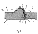
- FIG. 3 shows an example of a connection of two preferred sandwich elements 27 to a sealing tape 1 according to the invention shown.
- the sandwich elements 27 show in each case the two metal skins 11, 13, between which a foam layer 29 is introduced is.
- the sealing tape 1 closes the joint 31 of the sandwich element 27, so that no foam could escape during the foaming of the sandwich element 27.
- an adhesive tape 9 is arranged, which adheres firmly to the upper metal skin 13 is connected. This adhesive tape 9 ensures the secure guidance of the sealing tape 1 during the foaming process of the sandwich element 27.
- the assembly of Sandwich elements require an exact joining and compression of the sealing tapes.
- Sandwich elements up to 4 m high are often pressed together with a joint that is just as long.
- the sandwich elements are finally such as using conventional fasteners Screws connected together.
- the sealing tape provides the perfect soundproofing, weatherproof sealing of the joint. Changes in length of the expansion joint balanced so that no cracks or poor adhesion occur.
- the sealing tape according to the invention can also be designed in other variations be, in particular, the adhesive tape can have any geometry if it Form of the joint required.
Landscapes
- Engineering & Computer Science (AREA)
- Architecture (AREA)
- Civil Engineering (AREA)
- Structural Engineering (AREA)
- Physics & Mathematics (AREA)
- Electromagnetism (AREA)
- Laminated Bodies (AREA)
- Adhesive Tapes (AREA)
- Building Environments (AREA)
- Materials For Medical Uses (AREA)
- Adhesives Or Adhesive Processes (AREA)
- Body Structure For Vehicles (AREA)
Abstract
Description
- Fig. 1
- eine bevorzugte Ausführungsform des erfindungsgemäßen Dichtungsbandes;
- Fig. 2
- eine Anlage zur Herstellung von Sandwichelementen; und
- Fig. 3
- eine bevorzugte Ausführungsform eines Sandwichelements mit einem erfindungsgemäßen Dichtungsband.
Claims (8)
- Dichtungsband (1) mit einem Kern (3) aus weichem Schaumstoff, der eine erste (5) und eine zweite (7) Außenfläche aufweist, die gegenüberliegend angeordnet sind, wobei zumindest auf der ersten Außenfläche (5) eine Zugverstärkungsschicht (4) aufgebracht ist, dadurch gekennzeichnet, daß auf der Zugverstärkungsschicht (4) ein doppelseitig haftendes Klebeband (9) angeordnet ist, das auf der zur Zugverstärkungsschicht (4) hin gewandten Seite stark haftend und auf der anderen Seite schwächer haftend ausgestaltet ist, wobei die schwächer haftende Seite des Klebebands (9) derart ausgestaltet ist, daß sie auf Blech haftet, jedoch nicht auf Schaumstoff.
- Dichtungsband (1) nach Anspruch 1, dadurch gekennzeichnet, daß der Schaumstoffkern (3) aus Polyurethan besteht.
- Dichtungsband (1) nach Anspruch 1 oder 2, dadurch gekennzeichnet, daß der Schaumstoffkern (3) imprägniert ist, wobei das Imprägnat eine die verzögerte Rückstellung des Schaumstoffs hervorrufende Eigenschaft aufweist.
- Dichtungsband (1) nach einem der vorangehenden Ansprüche, dadurch gekennzeichnet, daß das Imprägnat eine wässrige Acrylatdispersion ist.
- Dichtungsband (1) nach einem der vorangehenden Ansprüche, dadurch gekennzeichnet, daß das Klebeband (9) die erste Außenfläche (5) des Dichtungsbandes (1) nur teilweise bedeckt.
- Dichtungsband (1) nach einem der vorangehenden Ansprüche, dadurch gekennzeichnet, daß das Klebeband (9) durch beidseitige, unterschiedlich ausgestaltete Acrylatdispersionen inhärent klebrig ausgebildet ist.
- Dichtungsband (1) nach Anspruch 6, dadurch gekennzeichnet, daß mindestens eine Acrylatdispersion (9) einen geeigneten Anteil an einem Tackyfierharz aufweist.
- Sandwichelement (27), das zwei Metallhäute (11, 13) aufweist, zwischen denen eine mit diesen verklebte Schaumstoffschicht (29) eingebracht ist, dadurch gekennzeichnet, daß mindestens eine Längsseite des Sandwichelements (29) durch ein Dichtungsband (1) gemäß einem der vorangehenden Ansprüche abgedichtet ist.
Applications Claiming Priority (2)
| Application Number | Priority Date | Filing Date | Title |
|---|---|---|---|
| DE20306687U | 2003-04-29 | ||
| DE20306687U DE20306687U1 (de) | 2003-04-29 | 2003-04-29 | Dichtungsband |
Publications (3)
| Publication Number | Publication Date |
|---|---|
| EP1473418A2 true EP1473418A2 (de) | 2004-11-03 |
| EP1473418A3 EP1473418A3 (de) | 2005-12-14 |
| EP1473418B1 EP1473418B1 (de) | 2006-05-31 |
Family
ID=32946539
Family Applications (1)
| Application Number | Title | Priority Date | Filing Date |
|---|---|---|---|
| EP04000999A Expired - Lifetime EP1473418B1 (de) | 2003-04-29 | 2004-01-19 | Dichtungsband |
Country Status (3)
| Country | Link |
|---|---|
| EP (1) | EP1473418B1 (de) |
| AT (1) | ATE328167T1 (de) |
| DE (2) | DE20306687U1 (de) |
Cited By (3)
| Publication number | Priority date | Publication date | Assignee | Title |
|---|---|---|---|---|
| EP2620566A3 (de) * | 2012-01-27 | 2014-03-05 | Tremco illbruck Produktion GmbH | Dichtband |
| EP2584110B1 (de) | 2011-10-21 | 2023-04-12 | Tremco CPG Germany GmbH | Dichtband |
| AT528027B1 (de) * | 2024-08-05 | 2025-09-15 | Horst Resch | Vorratsrolle mit einem Dichtungsband |
Families Citing this family (4)
| Publication number | Priority date | Publication date | Assignee | Title |
|---|---|---|---|---|
| DE102005058414A1 (de) * | 2005-12-07 | 2007-06-14 | Tremco Illbruck Produktion Gmbh | In einer Umhüllungsfolie aufgenommener Schaumstoffstreifen |
| DE102013209671A1 (de) * | 2013-05-24 | 2014-11-27 | Tesa Se | Abdichtung einer mit einem stiftartigen Verbindungselement bewirkten Verbindung zweier Bauteile |
| DE202013104268U1 (de) * | 2013-09-18 | 2015-01-09 | Tremco Illbruck Produktion Gmbh | Dichtband |
| US12392131B2 (en) | 2020-08-24 | 2025-08-19 | Hilti Aktiengesellschaft | Sealing profile and drywall |
Family Cites Families (5)
| Publication number | Priority date | Publication date | Assignee | Title |
|---|---|---|---|---|
| DE2312353A1 (de) * | 1973-03-13 | 1974-09-19 | Felix Preisler | Verfahren zur befestigung von waermedaemmplatten und dachhaut auf flachen bzw. wenig geneigten daechern |
| CH678871A5 (de) * | 1989-05-25 | 1991-11-15 | Huber+Suhner Ag | |
| DE8908489U1 (de) * | 1989-07-12 | 1989-08-31 | Rütgerswerke AG, 6000 Frankfurt | Wärmedämmung für Flachdächer |
| DE19609277C2 (de) * | 1996-03-08 | 1998-06-04 | Guenter Klaus | Selbstklebendes Abdeckmittel |
| DE29813307U1 (de) * | 1998-07-27 | 1999-12-09 | SALAMANDER INDUSTRIE-PRODUKTE GMBH, 86842 TüRKHEIM | Fugendichtungskörper |
-
2003
- 2003-04-29 DE DE20306687U patent/DE20306687U1/de not_active Expired - Lifetime
-
2004
- 2004-01-19 EP EP04000999A patent/EP1473418B1/de not_active Expired - Lifetime
- 2004-01-19 DE DE502004000642T patent/DE502004000642D1/de not_active Expired - Lifetime
- 2004-01-19 AT AT04000999T patent/ATE328167T1/de active
Cited By (4)
| Publication number | Priority date | Publication date | Assignee | Title |
|---|---|---|---|---|
| EP2584110B1 (de) | 2011-10-21 | 2023-04-12 | Tremco CPG Germany GmbH | Dichtband |
| EP2620566A3 (de) * | 2012-01-27 | 2014-03-05 | Tremco illbruck Produktion GmbH | Dichtband |
| AT528027B1 (de) * | 2024-08-05 | 2025-09-15 | Horst Resch | Vorratsrolle mit einem Dichtungsband |
| AT528027A4 (de) * | 2024-08-05 | 2025-09-15 | Horst Resch | Vorratsrolle mit einem Dichtungsband |
Also Published As
| Publication number | Publication date |
|---|---|
| ATE328167T1 (de) | 2006-06-15 |
| EP1473418A3 (de) | 2005-12-14 |
| DE502004000642D1 (de) | 2006-07-06 |
| DE20306687U1 (de) | 2004-09-02 |
| EP1473418B1 (de) | 2006-05-31 |
Similar Documents
| Publication | Publication Date | Title |
|---|---|---|
| DE2501096B2 (de) | Randleiste zur herstellung von isolierglasscheiben, mehrscheiben-isolierglas sowie verfahren zu seiner herstellung | |
| DE3402923A1 (de) | Verbundplatte sowie verfahren zur herstellung einer verbundplatte | |
| DE2854766C2 (de) | Verfahren zum Verkleben zweier Werkstücke sowie Klebestreifen zur Durchführung des Verfahrens | |
| DE7706988U1 (de) | Mehrschichtiges klebematerial in platten- oder streifenform | |
| EP2354410A2 (de) | Schaumstoff-Dichtstreifen und Fensterrahmen mit Schaumstoff-Dichtstreifen | |
| DE202013101372U1 (de) | Dichtband | |
| EP1473418B1 (de) | Dichtungsband | |
| AT516184B1 (de) | Anschlussprofil für an Putz angrenzende Bauteile | |
| EP1473419B1 (de) | Dichtungsband | |
| EP3448702A1 (de) | Gerüstband mit verstärkungsmittel | |
| EP3464742B1 (de) | Dichtungsstreifen zur abdichtung von fugen zwischen bauelementen sowie verfahren zur herstellung eines dichtungsstreifens | |
| DE3309338A1 (de) | Flachdichtungsring und verfahren zu seiner herstellung | |
| EP1956174B1 (de) | Profilschiene zum Positionieren eines Befestigungselements und Verfahren zum Herstellen einer Mehrfachverglasungseinheit | |
| DE3317548A1 (de) | Abschluss- und dichtungsrahmen fuer die innenkanten von oeffnungen in karosserien | |
| DE202007014100U1 (de) | Gittergewebestreifen | |
| EP3757306A1 (de) | Dichtband | |
| DE3010892C2 (de) | Tafelförmiges Bauelement | |
| AT505955A2 (de) | Verfahren zum beschichten eines abdeckprofils und wenigstens eines an einen abdeckflansch des abdeckprofils anschliessbaren ausgleichprofils einer abdeckvorrichtung für fussbodenbeläge mit einer deckschicht | |
| DE102014110541A1 (de) | Dichtungsstrang und Verfahren zu seiner Herstellung | |
| DE19611382A1 (de) | Schalplatte für Betonschalungen mit Kantenschutz und Zwischenschicht | |
| DE102018112777A1 (de) | Eckverbindung eines Dichtungsrahmens | |
| DE10126743A1 (de) | Platte nit Stirnflächen und Mitteln zur Verklebung der Stirnfläche mit der Stirnfläche einer weiteren Platte | |
| DE19904845C1 (de) | Verfahren zum Herstellen einer Furnierstreifenbahn unbegrenzter Länge | |
| DE20107230U1 (de) | Fugenabdichtung auf der Basis eines im beschichteten Bereich mindestens teilweise perforierten Vlies-Streifens | |
| EP4036347A1 (de) | Putzprofil mit einer überputzbaren folie auf einem seiner putzschenkel |
Legal Events
| Date | Code | Title | Description |
|---|---|---|---|
| PUAI | Public reference made under article 153(3) epc to a published international application that has entered the european phase |
Free format text: ORIGINAL CODE: 0009012 |
|
| AK | Designated contracting states |
Kind code of ref document: A2 Designated state(s): AT BE BG CH CY CZ DE DK EE ES FI FR GB GR HU IE IT LI LU MC NL PT RO SE SI SK TR |
|
| AX | Request for extension of the european patent |
Extension state: AL LT LV MK |
|
| PUAL | Search report despatched |
Free format text: ORIGINAL CODE: 0009013 |
|
| AK | Designated contracting states |
Kind code of ref document: A3 Designated state(s): AT BE BG CH CY CZ DE DK EE ES FI FR GB GR HU IE IT LI LU MC NL PT RO SE SI SK TR |
|
| AX | Request for extension of the european patent |
Extension state: AL LT LV MK |
|
| 17P | Request for examination filed |
Effective date: 20051107 |
|
| GRAP | Despatch of communication of intention to grant a patent |
Free format text: ORIGINAL CODE: EPIDOSNIGR1 |
|
| GRAS | Grant fee paid |
Free format text: ORIGINAL CODE: EPIDOSNIGR3 |
|
| GRAA | (expected) grant |
Free format text: ORIGINAL CODE: 0009210 |
|
| AK | Designated contracting states |
Kind code of ref document: B1 Designated state(s): AT BE BG CH CY CZ DE DK EE ES FI FR GB GR HU IE IT LI LU MC NL PT RO SE SI SK TR |
|
| PG25 | Lapsed in a contracting state [announced via postgrant information from national office to epo] |
Ref country code: IE Free format text: LAPSE BECAUSE OF FAILURE TO SUBMIT A TRANSLATION OF THE DESCRIPTION OR TO PAY THE FEE WITHIN THE PRESCRIBED TIME-LIMIT Effective date: 20060531 Ref country code: CZ Free format text: LAPSE BECAUSE OF FAILURE TO SUBMIT A TRANSLATION OF THE DESCRIPTION OR TO PAY THE FEE WITHIN THE PRESCRIBED TIME-LIMIT Effective date: 20060531 Ref country code: GB Free format text: LAPSE BECAUSE OF FAILURE TO SUBMIT A TRANSLATION OF THE DESCRIPTION OR TO PAY THE FEE WITHIN THE PRESCRIBED TIME-LIMIT Effective date: 20060531 Ref country code: SK Free format text: LAPSE BECAUSE OF FAILURE TO SUBMIT A TRANSLATION OF THE DESCRIPTION OR TO PAY THE FEE WITHIN THE PRESCRIBED TIME-LIMIT Effective date: 20060531 Ref country code: SI Free format text: LAPSE BECAUSE OF FAILURE TO SUBMIT A TRANSLATION OF THE DESCRIPTION OR TO PAY THE FEE WITHIN THE PRESCRIBED TIME-LIMIT Effective date: 20060531 Ref country code: RO Free format text: LAPSE BECAUSE OF FAILURE TO SUBMIT A TRANSLATION OF THE DESCRIPTION OR TO PAY THE FEE WITHIN THE PRESCRIBED TIME-LIMIT Effective date: 20060531 Ref country code: FI Free format text: LAPSE BECAUSE OF FAILURE TO SUBMIT A TRANSLATION OF THE DESCRIPTION OR TO PAY THE FEE WITHIN THE PRESCRIBED TIME-LIMIT Effective date: 20060531 Ref country code: IT Free format text: LAPSE BECAUSE OF FAILURE TO SUBMIT A TRANSLATION OF THE DESCRIPTION OR TO PAY THE FEE WITHIN THE PRESCRIBED TIME-LIMIT;WARNING: LAPSES OF ITALIAN PATENTS WITH EFFECTIVE DATE BEFORE 2007 MAY HAVE OCCURRED AT ANY TIME BEFORE 2007. THE CORRECT EFFECTIVE DATE MAY BE DIFFERENT FROM THE ONE RECORDED. Effective date: 20060531 |
|
| REG | Reference to a national code |
Ref country code: GB Ref legal event code: FG4D Free format text: NOT ENGLISH Ref country code: CH Ref legal event code: EP |
|
| REG | Reference to a national code |
Ref country code: IE Ref legal event code: FG4D Free format text: LANGUAGE OF EP DOCUMENT: GERMAN |
|
| REF | Corresponds to: |
Ref document number: 502004000642 Country of ref document: DE Date of ref document: 20060706 Kind code of ref document: P |
|
| AKX | Designation fees paid |
Designated state(s): AT BE BG CH CY CZ DE DK EE ES FI FR GB GR HU IE IT LI LU MC NL PT RO SE SI SK TR |
|
| PG25 | Lapsed in a contracting state [announced via postgrant information from national office to epo] |
Ref country code: SE Free format text: LAPSE BECAUSE OF FAILURE TO SUBMIT A TRANSLATION OF THE DESCRIPTION OR TO PAY THE FEE WITHIN THE PRESCRIBED TIME-LIMIT Effective date: 20060831 Ref country code: DK Free format text: LAPSE BECAUSE OF FAILURE TO SUBMIT A TRANSLATION OF THE DESCRIPTION OR TO PAY THE FEE WITHIN THE PRESCRIBED TIME-LIMIT Effective date: 20060831 |
|
| PG25 | Lapsed in a contracting state [announced via postgrant information from national office to epo] |
Ref country code: ES Free format text: LAPSE BECAUSE OF FAILURE TO SUBMIT A TRANSLATION OF THE DESCRIPTION OR TO PAY THE FEE WITHIN THE PRESCRIBED TIME-LIMIT Effective date: 20060911 |
|
| PG25 | Lapsed in a contracting state [announced via postgrant information from national office to epo] |
Ref country code: PT Free format text: LAPSE BECAUSE OF FAILURE TO SUBMIT A TRANSLATION OF THE DESCRIPTION OR TO PAY THE FEE WITHIN THE PRESCRIBED TIME-LIMIT Effective date: 20061031 |
|
| ET | Fr: translation filed | ||
| GBV | Gb: ep patent (uk) treated as always having been void in accordance with gb section 77(7)/1977 [no translation filed] |
Effective date: 20060531 |
|
| REG | Reference to a national code |
Ref country code: IE Ref legal event code: FD4D |
|
| PG25 | Lapsed in a contracting state [announced via postgrant information from national office to epo] |
Ref country code: MC Free format text: LAPSE BECAUSE OF NON-PAYMENT OF DUE FEES Effective date: 20070131 |
|
| PLBE | No opposition filed within time limit |
Free format text: ORIGINAL CODE: 0009261 |
|
| STAA | Information on the status of an ep patent application or granted ep patent |
Free format text: STATUS: NO OPPOSITION FILED WITHIN TIME LIMIT |
|
| 26N | No opposition filed |
Effective date: 20070301 |
|
| PG25 | Lapsed in a contracting state [announced via postgrant information from national office to epo] |
Ref country code: BG Free format text: LAPSE BECAUSE OF FAILURE TO SUBMIT A TRANSLATION OF THE DESCRIPTION OR TO PAY THE FEE WITHIN THE PRESCRIBED TIME-LIMIT Effective date: 20060831 |
|
| PG25 | Lapsed in a contracting state [announced via postgrant information from national office to epo] |
Ref country code: EE Free format text: LAPSE BECAUSE OF FAILURE TO SUBMIT A TRANSLATION OF THE DESCRIPTION OR TO PAY THE FEE WITHIN THE PRESCRIBED TIME-LIMIT Effective date: 20060531 |
|
| PG25 | Lapsed in a contracting state [announced via postgrant information from national office to epo] |
Ref country code: LU Free format text: LAPSE BECAUSE OF NON-PAYMENT OF DUE FEES Effective date: 20070119 Ref country code: CY Free format text: LAPSE BECAUSE OF FAILURE TO SUBMIT A TRANSLATION OF THE DESCRIPTION OR TO PAY THE FEE WITHIN THE PRESCRIBED TIME-LIMIT Effective date: 20060531 |
|
| PG25 | Lapsed in a contracting state [announced via postgrant information from national office to epo] |
Ref country code: HU Free format text: LAPSE BECAUSE OF FAILURE TO SUBMIT A TRANSLATION OF THE DESCRIPTION OR TO PAY THE FEE WITHIN THE PRESCRIBED TIME-LIMIT Effective date: 20061201 Ref country code: TR Free format text: LAPSE BECAUSE OF FAILURE TO SUBMIT A TRANSLATION OF THE DESCRIPTION OR TO PAY THE FEE WITHIN THE PRESCRIBED TIME-LIMIT Effective date: 20060531 |
|
| PG25 | Lapsed in a contracting state [announced via postgrant information from national office to epo] |
Ref country code: GR Free format text: LAPSE BECAUSE OF NON-PAYMENT OF DUE FEES Effective date: 20070131 |
|
| REG | Reference to a national code |
Ref country code: FR Ref legal event code: PLFP Year of fee payment: 13 |
|
| REG | Reference to a national code |
Ref country code: FR Ref legal event code: PLFP Year of fee payment: 14 |
|
| PGFP | Annual fee paid to national office [announced via postgrant information from national office to epo] |
Ref country code: NL Payment date: 20170119 Year of fee payment: 14 |
|
| PGFP | Annual fee paid to national office [announced via postgrant information from national office to epo] |
Ref country code: FR Payment date: 20170126 Year of fee payment: 14 Ref country code: CH Payment date: 20170126 Year of fee payment: 14 |
|
| PGFP | Annual fee paid to national office [announced via postgrant information from national office to epo] |
Ref country code: BE Payment date: 20170119 Year of fee payment: 14 Ref country code: AT Payment date: 20170123 Year of fee payment: 14 |
|
| PGFP | Annual fee paid to national office [announced via postgrant information from national office to epo] |
Ref country code: IT Payment date: 20170131 Year of fee payment: 14 |
|
| REG | Reference to a national code |
Ref country code: CH Ref legal event code: PL |
|
| REG | Reference to a national code |
Ref country code: NL Ref legal event code: MM Effective date: 20180201 |
|
| REG | Reference to a national code |
Ref country code: AT Ref legal event code: MM01 Ref document number: 328167 Country of ref document: AT Kind code of ref document: T Effective date: 20180119 |
|
| PG25 | Lapsed in a contracting state [announced via postgrant information from national office to epo] |
Ref country code: FR Free format text: LAPSE BECAUSE OF NON-PAYMENT OF DUE FEES Effective date: 20180131 |
|
| REG | Reference to a national code |
Ref country code: FR Ref legal event code: ST Effective date: 20180928 |
|
| REG | Reference to a national code |
Ref country code: BE Ref legal event code: MM Effective date: 20180131 |
|
| PG25 | Lapsed in a contracting state [announced via postgrant information from national office to epo] |
Ref country code: CH Free format text: LAPSE BECAUSE OF NON-PAYMENT OF DUE FEES Effective date: 20180131 Ref country code: BE Free format text: LAPSE BECAUSE OF NON-PAYMENT OF DUE FEES Effective date: 20180131 Ref country code: LI Free format text: LAPSE BECAUSE OF NON-PAYMENT OF DUE FEES Effective date: 20180131 Ref country code: AT Free format text: LAPSE BECAUSE OF NON-PAYMENT OF DUE FEES Effective date: 20180119 Ref country code: NL Free format text: LAPSE BECAUSE OF NON-PAYMENT OF DUE FEES Effective date: 20180201 |
|
| PG25 | Lapsed in a contracting state [announced via postgrant information from national office to epo] |
Ref country code: IT Free format text: LAPSE BECAUSE OF NON-PAYMENT OF DUE FEES Effective date: 20180119 |
|
| PGFP | Annual fee paid to national office [announced via postgrant information from national office to epo] |
Ref country code: DE Payment date: 20230127 Year of fee payment: 20 |
|
| REG | Reference to a national code |
Ref country code: DE Ref legal event code: R071 Ref document number: 502004000642 Country of ref document: DE |