EP1473208A1 - Verfahren zur Detektion einer Gleisbelegung - Google Patents
Verfahren zur Detektion einer Gleisbelegung Download PDFInfo
- Publication number
- EP1473208A1 EP1473208A1 EP03009575A EP03009575A EP1473208A1 EP 1473208 A1 EP1473208 A1 EP 1473208A1 EP 03009575 A EP03009575 A EP 03009575A EP 03009575 A EP03009575 A EP 03009575A EP 1473208 A1 EP1473208 A1 EP 1473208A1
- Authority
- EP
- European Patent Office
- Prior art keywords
- frequency
- receiver
- transmitter
- information
- track
- Prior art date
- Legal status (The legal status is an assumption and is not a legal conclusion. Google has not performed a legal analysis and makes no representation as to the accuracy of the status listed.)
- Granted
Links
- 238000000034 method Methods 0.000 title claims description 54
- 238000001514 detection method Methods 0.000 title description 22
- 230000008569 process Effects 0.000 title description 4
- 238000011084 recovery Methods 0.000 claims abstract description 4
- 230000005540 biological transmission Effects 0.000 claims description 15
- 238000005516 engineering process Methods 0.000 claims description 11
- 238000001228 spectrum Methods 0.000 claims description 8
- 230000004044 response Effects 0.000 claims description 7
- 230000003247 decreasing effect Effects 0.000 claims description 3
- 230000008859 change Effects 0.000 claims description 2
- 230000008878 coupling Effects 0.000 claims description 2
- 238000010168 coupling process Methods 0.000 claims description 2
- 238000005859 coupling reaction Methods 0.000 claims description 2
- 230000003252 repetitive effect Effects 0.000 claims 1
- 230000001360 synchronised effect Effects 0.000 description 10
- 238000010586 diagram Methods 0.000 description 4
- 230000001052 transient effect Effects 0.000 description 4
- 230000002238 attenuated effect Effects 0.000 description 2
- 230000008901 benefit Effects 0.000 description 2
- 230000002596 correlated effect Effects 0.000 description 2
- 230000000875 corresponding effect Effects 0.000 description 2
- 238000011156 evaluation Methods 0.000 description 2
- 230000006870 function Effects 0.000 description 2
- 238000009434 installation Methods 0.000 description 2
- 238000009413 insulation Methods 0.000 description 2
- 230000000630 rising effect Effects 0.000 description 2
- 230000003595 spectral effect Effects 0.000 description 2
- 230000007480 spreading Effects 0.000 description 2
- 238000003892 spreading Methods 0.000 description 2
- 230000003068 static effect Effects 0.000 description 2
- 238000003860 storage Methods 0.000 description 2
- 230000009471 action Effects 0.000 description 1
- 230000032683 aging Effects 0.000 description 1
- 230000006399 behavior Effects 0.000 description 1
- 238000005352 clarification Methods 0.000 description 1
- 239000004020 conductor Substances 0.000 description 1
- 238000013016 damping Methods 0.000 description 1
- 230000002950 deficient Effects 0.000 description 1
- 230000006735 deficit Effects 0.000 description 1
- 230000001419 dependent effect Effects 0.000 description 1
- 238000013461 design Methods 0.000 description 1
- 238000011161 development Methods 0.000 description 1
- 230000018109 developmental process Effects 0.000 description 1
- 238000009826 distribution Methods 0.000 description 1
- 230000005672 electromagnetic field Effects 0.000 description 1
- 238000001914 filtration Methods 0.000 description 1
- 230000006698 induction Effects 0.000 description 1
- 230000002045 lasting effect Effects 0.000 description 1
- 230000003137 locomotive effect Effects 0.000 description 1
- 230000007774 longterm Effects 0.000 description 1
- 239000000696 magnetic material Substances 0.000 description 1
- 239000002184 metal Substances 0.000 description 1
- 238000012544 monitoring process Methods 0.000 description 1
- 230000000284 resting effect Effects 0.000 description 1
- 230000002441 reversible effect Effects 0.000 description 1
- 238000005096 rolling process Methods 0.000 description 1
- 230000002123 temporal effect Effects 0.000 description 1
Images



Classifications
-
- B—PERFORMING OPERATIONS; TRANSPORTING
- B61—RAILWAYS
- B61L—GUIDING RAILWAY TRAFFIC; ENSURING THE SAFETY OF RAILWAY TRAFFIC
- B61L1/00—Devices along the route controlled by interaction with the vehicle or train
- B61L1/16—Devices for counting axles; Devices for counting vehicles
- B61L1/167—Circuit details
-
- B—PERFORMING OPERATIONS; TRANSPORTING
- B61—RAILWAYS
- B61L—GUIDING RAILWAY TRAFFIC; ENSURING THE SAFETY OF RAILWAY TRAFFIC
- B61L1/00—Devices along the route controlled by interaction with the vehicle or train
- B61L1/18—Railway track circuits
- B61L1/181—Details
- B61L1/188—Use of coded current
Definitions
- the present invention relates to a method for detection a track occupancy according to the preamble of the claim 1.
- Electronic detection systems and especially electronic Working axle counters have the disadvantage that they have the relevant working frequencies, e.g. 33 kHz, 43 kHz or 850 kHz or 1.2 MHz exposed to interference are and therefore have limited availability.
- the interference can cause, for example are made using electric eddy current brakes and converter locomotives.
- a relocation of the Working frequencies in supposedly interference-free areas bring no lasting success.
- No working frequency can actually cause interference be set outside the frequency band of the whole of sources of interference.
- an interference field due to a first coreless coil detect and provide a second coreless coil to the To compensate for interference. With this application none full compensation can be achieved as this is only for homogeneous interference fields.
- a wheel sensor which has two independent, has galvanically isolated wheel sensor systems. Detect them the wheel flange of a railway wheel. The principle of action is based on an alternating electromagnetic field energy is extracted by damping with metal. This System requires monitoring of correct assembly.
- the present invention is therefore based on the object specify a method for the detection of the track occupancy, that largely immune to electromagnetic interference is in a wide frequency range and no settings required during assembly.
- the method according to the invention opens up the possibility of existing installations on the track, be it now Axle counter or track circuits to continue to use.
- the transmitter unit and receiver unit requires this Method according to the invention no calibration and none level settings during assembly.
- the spectral is a broadband signal containing information ensures that occurring interference fields, for example by magnetic rail brakes or eddy current brakes caused, do not affect the safety-related Exercise detection of a track occupancy.
- the spectrally broadband signal containing information can be coded in different ways, for example through the Direct Sequence Spread Spectrum Technology (DSSS) or by repetitively sending a rising or falling Frequency curve. Because with this procedure there is always a recipient is present, this receiver can also be used for detection of static or transient interference fields and thus in the sense of a learning system the one to be sent out Frequency curve possibly outside or on Edge of an interference field and security be further improved. But this learning behavior is not absolutely necessary for the method according to the invention.
- DSSS Direct Sequence Spread Spectrum Technology
- Frequency shift keying technique also called: Frequency shift keying method
- Information S B spread in this way is modulated onto a carrier frequency.
- Fig. 1 shows two separated by a rail insulation 12 Track sections.
- a track section is in the distance d from a transmitter / transmitter 5 a receiving circuit with a Receiver / transmitter 6 connected.
- a typical area for such a distance d is 25 m in the interval. 2500 m.
- the one so modulated Carrier frequency when used in a track circuit 1 to the transmission coil 51 as Part of a transformer 5 switched.
- the secondary transmitter coil 52 as part of the transformer 5 is on the two rails 3rd a track section connected.
- the receiver / transmitter 6 has a reception coil 62 in the primary circuit and Secondary circuit on a receiving coil 61.
- the principal Function of such a track circuit in DC or AC technology is the following: Reacts to a resting track circuit a receiving device on a free track and that Track relay or electronic detection "picks up". If there is a wagon on the track section, change the electrical conditions. There is a shunt, so that by the receiving device only a small one Residual current flows. This determines that the section is occupied because the track relay then no longer "picks up”.
- This structure has the consequence that all frequently occurring Faults such as circuit interruptions (e.g. by a Wire break or defective fuses) to an alleged lead occupied track section.
- This procedure in DCoder AC technology has the disadvantage that reverse currents can simulate an assignment in the rails that do not display any assignment by an axle or vehicle.
- the spread signal modulated onto a carrier frequency band is broadband.
- the specified upper limit of the frequency band is explained by the fact that emission limit values must be observed above this frequency.
- the level of the signal S B 'received by the receiver 6 in the receiving coil 62 depends on the presence of a wheel 1 in the immediate vicinity of the transmitter / receiver arranged on the rail. In a receiving device (not shown in the figures), this signal S B 'must be despread. This is generally much more complex than spreading.
- the transmission clock is present directly in the reception device, because the transmission and reception device can be implemented directly next to one another or as an integrated device.
- This essential requirement generally does not apply to a message transmission using DSSS technology.
- no special synchronization effort is required in the receiving device.
- the received signal S B ' is in turn XOR-linked with the same Barker code B.
- the received signal S B ' has a profile S i at point i .
- a non-ideal course also occurs at the other points, but this is not shown in FIG. 5, but is only shown as an example for point i.
- This signal S i deviates by D i from the average signal strength S Avg .
- the deviation D i is then multiplied by -1 if the value of the Barker code at point i is 1.
- the result R i is calculated from this value added to the mean signal strength S Avg .
- the transmitted spread S B can nevertheless be regenerated as information S.
- the following frequencies or a frequency band from the frequency band listed below are used as examples for the transmission: 10 kHz .. 30 MHz.
- the information S is spread with a further Barker code B 2 , this code comprising m 2 digits.
- the spread signal S B2 is modulated on a carrier frequency band which is disjunct to the first carrier frequency band.
- No special conditions apply to the Barker Code B 2 , in particular the lengths m and m 2 can be different.
- a redundant two-channel system for the detection of a track occupancy is created, which is largely immune to interference on certain frequency bands and thus optimally fulfills the security requirements.
- no second installation of facilities on the track is required.
- Such a second channel with a further Barker code B 2 can be implemented with relatively little effort.
- the second embodiment of the present invention will based on the "magnetic" implementation form according to the 2 and 3 explained.
- the receiving coils 9a and 9b detect over the field lines 13 the spectrum emitted by the transmitter coil 5.
- the level this spectrum depends on the presence of a Wheel or an object made of a magnetic material between transmitter coil 5 and receiver coil 9a and 9b.
- a reception level P S is shown at a current level distance P D , it is assumed that an interference field D f is present in a small sub-area around a frequency f.
- the above-mentioned term "currently" means for the frequency f in question at a specific point in time.
- This reception level occurs with a reception coil 9a or 9b.
- This interference field is of course part of the received signal S B , with the level P S ,. For clarification, however, this is particularly designated D f in FIG.
- a self-calibration can determine whether the respective level difference P D between P S and P S corresponds to the presence of a wheel or not.
- This level difference P D is "falsified” by the aforementioned interference field.
- this is irrelevant for the determination of the presence or absence of a wheel when the respective distance P D is detected in discrete intervals over the frequency P D range [f 1 .. f 12 ], continuously summed up and finally averaged.
- “outliers" due to an interference field have no influence on the aforementioned determination of the presence or absence of a wheel.
- the interference fields are highly transient, so that with the specified repetition T REP in the range of 10 - 2000 ⁇ s, the current state regarding the presence / absence of a wheel on a sensor is determined several times.
- FIG. 8 shows the evaluation of the frequency profiles f a and f b generated according to FIG. 6a in an implementation with digital signal processors in a basic representation.
- the transmission device 50 has a voltage-controlled oscillator 55 (VCO voltage controlled oscillator).
- a controller 56 generates a corresponding voltage profile for the desired frequency profile.
- Not shown in FIG. 9 is a possible return to avoid transient or quasi-static interference fields detected in the receiving coils 9a and 9b.
- a transmit clock generator 54 is provided for determining the respective distance T from the two frequency profiles f a , f b as well as for repeating T REP .
- the receiving coils 9a and 9b are each connected to a broadband filter 71.
- the transmit clock generator is also connected to bandwidth-attenuated filters 71 in order to supply the received level of the respective frequency to the A / D converters 72 in the respective time pattern.
- the digital values of the levels in discrete time intervals are levels at certain frequencies, see FIG. 6c. Although the frequency is indicated on the abscissa, in a method with, for example, a linearly increasing frequency, this abscissa is also underlaid with a time axis.
- These digital levels are subjected to a reference storage 64 over time in order to be able to compensate for any signs of aging.
- the time constant here is on the order of weeks or months.
- the above-mentioned digital signals are used for wheel or axle recovery, as explained further above in relation to FIGS.
- the result is a value of ⁇ 1.
- the sign contains the direction of travel.
- the long-term feedback of the stored reference values means that this embodiment of the present invention does not require any external calibration.
- the aforementioned value ⁇ 1 is further evaluated in the axle counting electronics 80 in a known manner.
- first profile f a can also be designed to rise and the second profile f b to decrease.
- the method explained above can also be carried out in two channels. Independent transmission devices 6c and 6d are provided for a second channel, which generate a frequency response f c and f d as shown in FIG. 6a. Regardless of the course f a and f b , the corresponding courses f c and f d can be registered in the receiving coils 9c and 9d and analyzed or correlated in the receiving devices 6c and 6b.
- This two-channel version enables the required security requirements with regard to redundancy and independence to be met.
- the transmitter coil 5 is a static element. Any impairment of the function of the transmitter coil 5 can be determined from the transmitter side and is therefore independent of signals from the receiving circuits.
Landscapes
- Engineering & Computer Science (AREA)
- Automation & Control Theory (AREA)
- Mechanical Engineering (AREA)
- Train Traffic Observation, Control, And Security (AREA)
- Arrangements For Transmission Of Measured Signals (AREA)
- Length Measuring Devices With Unspecified Measuring Means (AREA)
Abstract
Description
- Figur 1
- Prinzipdarstellung eines Gleisstromkreises bei Anwendung einer ersten Ausführungsform der vorliegenden Erfindung;
- Figur 2
- Anordnung von Sende- und Empfangsspulen am Gleis;
- Figur 3
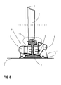
- Aufbau eines Radsensors in montiertem Zustand an einer Schiene;
- Figur 4
- Prinzipdarstellung der Spreizung eines Signals für die DSSS-Technik;
- Figur 5
- Darstellung eines gestörten Signals SB';
- Figur 6a
- Darstellung des zeitlich linearen FSK-Verfahrens
- Figur 6b
- Darstellung des zeitlich logarithmischen FSK-Verfahrens;
- Figur 6c
- Darstellung des Verlaufes des Sende- und Empfangspegels über ein Frequenzband beim FSK-Verfahren;
- Figur 7
- Prinzipschema zur Raddetektion für FSK-Verfahren;
- Figur 8
- Prinzipschema zur Raddetektion für FSK-Verfahren für digitalen Signalprozessoren.
10 kHz .. 30 MHz.
- 1
- Rad
- 2
- Radkranz
- 3
- Schiene
- 4
- Schwelle, Oberkante Schwelle
- 5
- Sender, Übertrager
- 5a
- 1. Sendeeinrichtung für ersten Kanal mit synchronisiertem Träger der Frequenz fa
- 5b
- 2. Sendeeinrichtung ersten Kanal mit synchronisiertem Träger der Frequenz fb
- 5c
- 3. Sendeeinrichtung für zweiten Kanal mit synchronisiertem Träger der Frequenz fc
- 5d
- 4. Sendeeinrichtung für zweiten Kanal mit synchronisiertem Träger der Frequenz fd
- 6
- Empfänger, Übertrager
- 6a
- 1. Empfangseinrichtung für ersten Kanal mit synchronisiertem Bandpassfilter
- 6b
- 2. Empfangseinrichtung für ersten Kanal mit synchronisiertem Bandpassfilter
- 6c
- 1. Empfangseinrichtung für zweiten Kanal mit synchronisiertem Bandpassfilter
- 6d
- 2. Empfangseinrichtung für zweiten Kanal mit synchronisiertem Bandpassfilter
- 7
- Befestigungsmittel für Sender/Empfänger
- 8
- Anschlussleitungen
- 9
- Radsensor
- 9a
- 1. Empfänger/Empfangsspule für ersten Kanal
- 9b
- 2. Empfänger/Empfangsspule für ersten Kanal
- 9c
- 1. Empfänger/Empfangsspule für zweiten Kanal
- 9d
- 2. Empfänger/Empfangsspule für zweiten Kanal
- 10
- Anschlussklemme
- 11
- Geleise
- 12
- Schienenisolierung
- 13
- Darstellung Verlauf Feldlinien
- 20
- Generator für Repetitionszeit
- 50
- Sendeeinrichtung
- 51
- Sendespule Primärkreis, Übertrager
- 52
- Sendespule Sekundärkreis, Übertrager
- 53
- Verstärker
- 54
- Sendetakt
- 55
- spannungsgesteuerter Oszillator, VCO Voltage controlled oscilltor
- 56
- Steuerung für Frequenz- bzw. Spannungsverlauf
- 60
- Empfangseinrichtung
- 61
- Empfängerspule Sekundärkreis, Übertrager
- 62
- Empfängerspule Primärkreis, Übertrager
- 63
- Achsrückgewinnung, ± 1
- 64
- Referenzwertspeicherung über die Zeit
- 70
- Analysefilterdatenbank
- 71
- bandbreitenbedämpfter Filter
- 72
- Analog/Digital-Wandler
- 80
- Achszählelektronik
- B, B2
- Barker Code
- Df
- Störfeld um eine Frequenz f
- d
- Abstand
- Di
- Abweichung
- f
- Frequenz
- fa, fb, fc, fd
- Frequenzverläufe für FSK-Verfahren
- fd1' fd2
- Untere, obere Frequenz eines Störbandes
- f1, f2
- Untere, obere Frequenz für FSK-Verfahren
- i
- laufender Index zur Kennzeichnung einer Stelle des Barker Codes, i = 1, .., m
- m, m2
- Breite des Barker Code in Bit, Anzahl Stellen des Barker Code
- n
- Breite der Information S in Bit
- p
- Pegel
- Ps, Ps,
- Sendepegel, Empfangspegel
- PD
- Pegelunterschied zwischen Ps, Ps
- S
- Information
- SAvg
- mittlere Signalstärke
- SB
- gespreiztes Signal, Nutzsignal
- SB'
- empfangenes Signal in gespreizter Darstellung
- Si
- Empfangenes Signal an der Stelle i
- Trep
- Repetionszeit
- Tab
- Folgezeit zwischen zwei Frequenzverläufen fa und fb
- DC
- Direct Current, Gleichstrom
- AC
- Alternating Current
- GFM
- Gleisfreimeldesystem
- DSSS
- Direct Sequence Spread Spectrum
- FSK
- Frequency Sweep Keying
Claims (15)
- Verfahren zur Feststellung einer Geleisebelegung durch:A1 einen an einer Schiene (3) angebrachten einen Sender (5) und Empfänger (6) enthaltenden Radsensor (9), der eine Magnetfeldänderung infolge eines die Schiene (3) überfahrenden Eisenbahnrades (1) registriert,
oderA2 einen durch zwei Schienen (3) gebildeten einen Sender (5) und Empfänger (6) aufweisenden Gleisstromkreis, der beim Befahren durch ein Eisenbahnfahrzeug kurzgeschlossen wird, wobei der Kurzschluss im Empfänger registrierbar ist;
gekennzeichnet durch die Verfahrensschritte:B der Sender (5) wird mit einem in einer Sendeeinheit (50; 5a, 5b, ..) generierten spektral breitbandigen eine Information (S) enthaltendem Signal (SB) beaufschlagt;C vom Empfänger (6) registrierte Signale (SB') werden einer Empfangseinheit (60, 6a, 6b, ..) zur Wiedergewinnung der im Verfahrensschritt B ausgesendeten Information (S) zugeführt, wobei Sendeeinheit (50; 5a, 5b, ..)und Empfangseinheit (60; 6a, 6b, ..) gekoppelt sind;D auftretende unterschiedliche Pegel des registrierten Signals (SB') werden zur Feststellung der Geleisebelegung herangezogen. - Verfahren nach Anspruch 1,
dadurch gekennzeichnet, dass
im Verfahrensschritt B in der Sendeeinheit (50; 5a, 5b, ..) die zu übertragende Information (S) in Direct Sequence spread Spectrum Technik (DSSS) mit einem Code (B) gespreizt wird und auf ein Trägerfrequenzband moduliert wird. - Verfahren nach Anspruch 2,
dadurch gekennzeichnet, dass
im Verfahrensschritt C zur Kopplung von Sendeeinheit (50; 5a, 5b, ..) und Empfangseinheit (60; 6a, 6b, ..) der Sendetakt (54; 20) der Empfangseinheit (60; 6a, 6b, ..) zugeführt wird. - Verfahren nach Anspruch 2 oder 3
dadurch gekennzeichnet, dass
im Verfahrensschritt B die zu übertragende Information (S) mit zwei verschiedenen Codes (B, B2) gespreizt wird und auf disjunkte Trägerfrequenzbänder moduliert werden. - Verfahren nach einem der Ansprüche 2 bis 4,
dadurch gekennzeichnet, dass
das Trägerfrequenzband einen Bereich von 10 kHz bis 30 MHz aufweist. - Verfahren nach Anspruch 1,
dadurch gekennzeichnet, dass
im Verfahrensschritt B in der Sendeeinheit (50; 5a, 5b, ..) die zu übertragende Information (S) durch Aussendung zweier aufeinanderfolgender Frequenzverläufe (Tab, fa, fb, ..) codiert wird, wobei die beiden Verläufe repetitiv (TRep ) ausgesendet werden. - Verfahren nach Anspruch 6,
dadurch gekennzeichnet, dass
im Verfahrensschritt B in der Sendeeinheit (50; 5a, 5b, ..) die zu übertragende Information (S) durch Aussendung vierer aufeinanderfolgender Frequenzverläufe (Tab, fa, fb, fc, fd) codiert wird, wobei die vier Verläufe repetitiv (TRep ) ausgesendet werden. - Verfahren nach Anspruch 6 oder 7,
dadurch gekennzeichnet, dass
ein Generator (20) für das repetitive Aussenden vorgesehen ist und dass der Generator mit der Sendeeinheit (5a, 5b, ..) und mit der Empfangseinheit (6a, 6b, ..) gekoppelt ist. - Verfahren nach einem der Ansprüche 6 bis 8,
dadurch gekennzeichnet, dass
der Frequenzverlauf (fa, fb,..) über die Zeit linear ansteigend oder linear fallend ist. - Verfahren nach einem der Ansprüche 6 bis 8,
dadurch gekennzeichnet, dass
der Frequenzverlauf (fa, fb,..) über die Zeit logarithmisch ansteigend oder logarithmisch fallend ist. - Verfahren nach einem der Ansprüche 6 bis 8,
dadurch gekennzeichnet, dass
der Frequenzverlauf (fa, fb,..) über die Zeit monoton ansteigend oder monoton fallend ist. - Verfahren nach einem der Ansprüche 6 bis 11,
dadurch gekennzeichnet, dass
vor Ausführung des Verfahrensschrittes B ein vom Empfänger erfasstes Störfeld analysiert wird und dass im Verfahrensschritt B der Frequenzverlauf (fa, fb ,..) ausserhalb oder am Rande des Störfeldes festgelegt wird. - Verfahren nach einem der Ansprüche 6 bis 12,
dadurch gekennzeichnet, dass
die Frequenzverläufe (fa, fb ,..) innerhalb eines Bandes von 10 kHz bis 10 MHz angelegt werden. - Verfahren nach einem der Ansprüche 1 bis 13,
dadurch gekennzeichnet, dass
der Radsensor (9) zur Detektion der Überfahrrichtung zwei Empfangsspulen (9a, 9b) aufweist. - Verfahren nach einem der Ansprüche 1 bis 13,
dadurch gekennzeichnet, dass
der Radsensor (9) zur Detektion der Überfahrrichtung vier Empfangsspulen (9a, 9b, 9c, 9d) aufweist.
Priority Applications (4)
| Application Number | Priority Date | Filing Date | Title |
|---|---|---|---|
| ES03009575T ES2247447T3 (es) | 2003-04-29 | 2003-04-29 | Procedimiento para la deteccion de la ocupacion de las vias ferreas. |
| DE50301090T DE50301090D1 (de) | 2003-04-29 | 2003-04-29 | Verfahren zur Detektion einer Gleisbelegung |
| AT03009575T ATE303277T1 (de) | 2003-04-29 | 2003-04-29 | Verfahren zur detektion einer gleisbelegung |
| EP03009575A EP1473208B1 (de) | 2003-04-29 | 2003-04-29 | Verfahren zur Detektion einer Gleisbelegung |
Applications Claiming Priority (1)
| Application Number | Priority Date | Filing Date | Title |
|---|---|---|---|
| EP03009575A EP1473208B1 (de) | 2003-04-29 | 2003-04-29 | Verfahren zur Detektion einer Gleisbelegung |
Publications (2)
| Publication Number | Publication Date |
|---|---|
| EP1473208A1 true EP1473208A1 (de) | 2004-11-03 |
| EP1473208B1 EP1473208B1 (de) | 2005-08-31 |
Family
ID=32981765
Family Applications (1)
| Application Number | Title | Priority Date | Filing Date |
|---|---|---|---|
| EP03009575A Expired - Lifetime EP1473208B1 (de) | 2003-04-29 | 2003-04-29 | Verfahren zur Detektion einer Gleisbelegung |
Country Status (4)
| Country | Link |
|---|---|
| EP (1) | EP1473208B1 (de) |
| AT (1) | ATE303277T1 (de) |
| DE (1) | DE50301090D1 (de) |
| ES (1) | ES2247447T3 (de) |
Cited By (3)
| Publication number | Priority date | Publication date | Assignee | Title |
|---|---|---|---|---|
| DE102007031139A1 (de) * | 2007-06-29 | 2009-01-02 | Siemens Ag | Verfahren zur Erhöhung der Störsicherheit eines Radsensors und Radsensors zur Durchführung des Verfahrens |
| WO2009098101A1 (de) * | 2008-02-04 | 2009-08-13 | Siemens Aktiengesellschaft | Verfahren zur erhöhung der störsicherheit eines radsensors und radsensor zur durchführung des verfahrens |
| CN112214876A (zh) * | 2020-09-11 | 2021-01-12 | 通号城市轨道交通技术有限公司 | Cbtc信号测试系统中计轴建模方法、装置与电子设备 |
Families Citing this family (1)
| Publication number | Priority date | Publication date | Assignee | Title |
|---|---|---|---|---|
| ES2531016B1 (es) * | 2014-03-18 | 2016-02-12 | Logistica Y Telecomunicacion, S.L. (Logytel) | Dispositivo sensor y procedimiento para detectar el paso de los ejes de los trenes por las vías |
Citations (5)
| Publication number | Priority date | Publication date | Assignee | Title |
|---|---|---|---|---|
| DE3307689A1 (de) * | 1983-03-04 | 1984-09-06 | Standard Elektrik Lorenz Ag, 7000 Stuttgart | Schaltungsanordnung zum betrieb eines induktiv arbeitenden schienenkontakts |
| GB2149275A (en) * | 1983-10-26 | 1985-06-05 | Standard Telephones Cables Ltd | Identity card recognition system |
| JPH08183453A (ja) * | 1994-12-28 | 1996-07-16 | Nippon Signal Co Ltd:The | 列車検知装置 |
| DE19709840A1 (de) * | 1997-02-28 | 1998-09-03 | Siemens Ag | Einrichtung für die Achszählung zum Unterscheiden von Radbeeinflussungen und Nicht-Radbeeinflussungen |
| JP2001063573A (ja) * | 1999-08-27 | 2001-03-13 | Mitsubishi Electric Corp | 列車検知装置 |
-
2003
- 2003-04-29 DE DE50301090T patent/DE50301090D1/de not_active Expired - Lifetime
- 2003-04-29 AT AT03009575T patent/ATE303277T1/de active
- 2003-04-29 ES ES03009575T patent/ES2247447T3/es not_active Expired - Lifetime
- 2003-04-29 EP EP03009575A patent/EP1473208B1/de not_active Expired - Lifetime
Patent Citations (5)
| Publication number | Priority date | Publication date | Assignee | Title |
|---|---|---|---|---|
| DE3307689A1 (de) * | 1983-03-04 | 1984-09-06 | Standard Elektrik Lorenz Ag, 7000 Stuttgart | Schaltungsanordnung zum betrieb eines induktiv arbeitenden schienenkontakts |
| GB2149275A (en) * | 1983-10-26 | 1985-06-05 | Standard Telephones Cables Ltd | Identity card recognition system |
| JPH08183453A (ja) * | 1994-12-28 | 1996-07-16 | Nippon Signal Co Ltd:The | 列車検知装置 |
| DE19709840A1 (de) * | 1997-02-28 | 1998-09-03 | Siemens Ag | Einrichtung für die Achszählung zum Unterscheiden von Radbeeinflussungen und Nicht-Radbeeinflussungen |
| JP2001063573A (ja) * | 1999-08-27 | 2001-03-13 | Mitsubishi Electric Corp | 列車検知装置 |
Non-Patent Citations (2)
| Title |
|---|
| PATENT ABSTRACTS OF JAPAN vol. 1996, no. 11 29 November 1996 (1996-11-29) * |
| PATENT ABSTRACTS OF JAPAN vol. 2000, no. 20 10 July 2001 (2001-07-10) * |
Cited By (6)
| Publication number | Priority date | Publication date | Assignee | Title |
|---|---|---|---|---|
| DE102007031139A1 (de) * | 2007-06-29 | 2009-01-02 | Siemens Ag | Verfahren zur Erhöhung der Störsicherheit eines Radsensors und Radsensors zur Durchführung des Verfahrens |
| WO2009003810A1 (de) * | 2007-06-29 | 2009-01-08 | Siemens Aktiengesellschaft | Verfahren zur erhöhung der störsicherheit eines radsensors und radsensor zur durchführung des verfahrens |
| WO2009098101A1 (de) * | 2008-02-04 | 2009-08-13 | Siemens Aktiengesellschaft | Verfahren zur erhöhung der störsicherheit eines radsensors und radsensor zur durchführung des verfahrens |
| CN101939201B (zh) * | 2008-02-04 | 2013-05-15 | 西门子公司 | 用于提高车轮传感器的抗干扰性的方法以及用于执行该方法的车轮传感器 |
| AU2009211471B2 (en) * | 2008-02-04 | 2013-09-05 | Siemens Mobility GmbH | Method for increasing the interference resistance of a wheel sensor and wheel sensor for carrying out the method |
| CN112214876A (zh) * | 2020-09-11 | 2021-01-12 | 通号城市轨道交通技术有限公司 | Cbtc信号测试系统中计轴建模方法、装置与电子设备 |
Also Published As
| Publication number | Publication date |
|---|---|
| ATE303277T1 (de) | 2005-09-15 |
| ES2247447T3 (es) | 2006-03-01 |
| EP1473208B1 (de) | 2005-08-31 |
| DE50301090D1 (de) | 2005-10-06 |
Similar Documents
| Publication | Publication Date | Title |
|---|---|---|
| DE10063675C1 (de) | Verfahren und Vorrichtung zur Übertragung von Daten auf wenigstens einer elektrischen Energieversorgungsleitung | |
| EP2084048B1 (de) | Verfahren und einrichtung zum auswerten von messdaten in eisenbahngleisstromkreisen | |
| EP2403745B1 (de) | Vorrichtungen zur detektion des belegt- oder freizustandes eines gleisabschnitts sowie verfahren zum betreiben solcher vorrichtungen | |
| EP0983166A1 (de) | Verfahren und vorrichtung zur übertragung von digitalen daten von einer messstation eines insassenschutzsystems eines kraftfahrzeugs zu einem airbagsteuergerät | |
| DE102009010907A1 (de) | Vorrichtung zur Detektion des Belegt- und Freizustandes eines Gleisabschnitts sowie Verfahren zum Betreiben einer solchen Vorrichtung | |
| CN106080666A (zh) | 用于生成铁路车辆定位信号的车载系统 | |
| EP3475142B1 (de) | Sensoreinrichtung und verfahren zum erfassen einer magnetfeldänderung | |
| EP2868548B1 (de) | Verfahren zur Überwachung eines Schaltungszustandes eines Schalters eines Zugsicherungssystem, sowie Zugsicherungssystem | |
| EP2673179A1 (de) | Vorrichtung zur detektion des belegt- oder freizustandes eines gleisabschnitts sowie verfahren zum betreiben einer solchen vorrichtung | |
| EP1473208B1 (de) | Verfahren zur Detektion einer Gleisbelegung | |
| DE19709840C2 (de) | Einrichtung für die Achszählung zum Unterscheiden von Radbeeinflussungen und Nicht-Radbeeinflussungen | |
| EP3658927A1 (de) | Verfahren und anordnung zum erkennen von teilentladungen bei einem elektrischen betriebsmittel | |
| DE10054745A1 (de) | Vorrichtung zur Umwandlung einer physikalischen Meßgröße in ein elektrisches Signal und Verfahren zur sicheren Übertragung von Sensorsignalen | |
| EP3042805A1 (de) | Vorrichtung zum überwachen eines bordnetzes | |
| DE2602460A1 (de) | Steuereinrichtung fuer schienengebundenes fahrzeug | |
| DE4405809C2 (de) | Verfahren und Einrichtung zum Identifizieren einer Wechselspannung in einem Stromversorgungsnetz mit mehreren Wechselspannungen | |
| DE102017214996A1 (de) | Verfahren zum Bestimmen der Entfernung einer Reflexionsstelle auf einem elektrischen Leiter | |
| WO2013023647A2 (de) | Anordnung und verfahren zur steuerung einer induktiven energieversorgungseinrichtung für elektrofahrzeuge | |
| EP1491864A2 (de) | Verfahren und Vorrichtung zur Funktionsprüfung eines induktiven Sensors | |
| DE112005001554B4 (de) | Elektrisches Zeichenabgabesystem | |
| EP0300363B1 (de) | Schaltungsanordung zur Gleisfreimeldung | |
| DE4423785C1 (de) | Verfahren zum Ermitteln der Position einer bestimmten Achse eines Schienenfahrzeuges auf einem Gleisabschnitt | |
| WO2007134992A1 (de) | Vorrichtung zur detektion des belegt- oder freizustandes eines gleisabschnittes | |
| EP3587214A1 (de) | Balisensteuerungsvorrichtung | |
| AT501703A1 (de) | System zur induktiven zugsicherung |
Legal Events
| Date | Code | Title | Description |
|---|---|---|---|
| PUAI | Public reference made under article 153(3) epc to a published international application that has entered the european phase |
Free format text: ORIGINAL CODE: 0009012 |
|
| AK | Designated contracting states |
Kind code of ref document: A1 Designated state(s): AT BE BG CH CY CZ DE DK EE ES FI FR GB GR HU IE IT LI LU MC NL PT RO SE SI SK TR |
|
| AX | Request for extension of the european patent |
Extension state: AL LT LV MK |
|
| 17P | Request for examination filed |
Effective date: 20041118 |
|
| GRAP | Despatch of communication of intention to grant a patent |
Free format text: ORIGINAL CODE: EPIDOSNIGR1 |
|
| GRAS | Grant fee paid |
Free format text: ORIGINAL CODE: EPIDOSNIGR3 |
|
| GRAA | (expected) grant |
Free format text: ORIGINAL CODE: 0009210 |
|
| AKX | Designation fees paid |
Designated state(s): AT BE BG CH CY CZ DE DK EE ES FI FR GB GR HU IE IT LI LU MC NL PT RO SE SI SK TR |
|
| AK | Designated contracting states |
Kind code of ref document: B1 Designated state(s): AT BE BG CH CY CZ DE DK EE ES FI FR GB GR HU IE IT LI LU MC NL PT RO SE SI SK TR |
|
| PG25 | Lapsed in a contracting state [announced via postgrant information from national office to epo] |
Ref country code: RO Free format text: LAPSE BECAUSE OF FAILURE TO SUBMIT A TRANSLATION OF THE DESCRIPTION OR TO PAY THE FEE WITHIN THE PRESCRIBED TIME-LIMIT Effective date: 20050831 Ref country code: CZ Free format text: LAPSE BECAUSE OF FAILURE TO SUBMIT A TRANSLATION OF THE DESCRIPTION OR TO PAY THE FEE WITHIN THE PRESCRIBED TIME-LIMIT Effective date: 20050831 Ref country code: IE Free format text: LAPSE BECAUSE OF FAILURE TO SUBMIT A TRANSLATION OF THE DESCRIPTION OR TO PAY THE FEE WITHIN THE PRESCRIBED TIME-LIMIT Effective date: 20050831 Ref country code: FI Free format text: LAPSE BECAUSE OF FAILURE TO SUBMIT A TRANSLATION OF THE DESCRIPTION OR TO PAY THE FEE WITHIN THE PRESCRIBED TIME-LIMIT Effective date: 20050831 Ref country code: SK Free format text: LAPSE BECAUSE OF FAILURE TO SUBMIT A TRANSLATION OF THE DESCRIPTION OR TO PAY THE FEE WITHIN THE PRESCRIBED TIME-LIMIT Effective date: 20050831 Ref country code: SI Free format text: LAPSE BECAUSE OF FAILURE TO SUBMIT A TRANSLATION OF THE DESCRIPTION OR TO PAY THE FEE WITHIN THE PRESCRIBED TIME-LIMIT Effective date: 20050831 |
|
| REG | Reference to a national code |
Ref country code: CH Ref legal event code: EP Ref country code: GB Ref legal event code: FG4D Free format text: NOT ENGLISH |
|
| REG | Reference to a national code |
Ref country code: IE Ref legal event code: FG4D Free format text: LANGUAGE OF EP DOCUMENT: GERMAN |
|
| REF | Corresponds to: |
Ref document number: 50301090 Country of ref document: DE Date of ref document: 20051006 Kind code of ref document: P |
|
| GBT | Gb: translation of ep patent filed (gb section 77(6)(a)/1977) |
Effective date: 20051003 |
|
| PG25 | Lapsed in a contracting state [announced via postgrant information from national office to epo] |
Ref country code: DK Free format text: LAPSE BECAUSE OF FAILURE TO SUBMIT A TRANSLATION OF THE DESCRIPTION OR TO PAY THE FEE WITHIN THE PRESCRIBED TIME-LIMIT Effective date: 20051130 Ref country code: BG Free format text: LAPSE BECAUSE OF FAILURE TO SUBMIT A TRANSLATION OF THE DESCRIPTION OR TO PAY THE FEE WITHIN THE PRESCRIBED TIME-LIMIT Effective date: 20051130 Ref country code: GR Free format text: LAPSE BECAUSE OF FAILURE TO SUBMIT A TRANSLATION OF THE DESCRIPTION OR TO PAY THE FEE WITHIN THE PRESCRIBED TIME-LIMIT Effective date: 20051130 Ref country code: SE Free format text: LAPSE BECAUSE OF FAILURE TO SUBMIT A TRANSLATION OF THE DESCRIPTION OR TO PAY THE FEE WITHIN THE PRESCRIBED TIME-LIMIT Effective date: 20051130 |
|
| PG25 | Lapsed in a contracting state [announced via postgrant information from national office to epo] |
Ref country code: PT Free format text: LAPSE BECAUSE OF FAILURE TO SUBMIT A TRANSLATION OF THE DESCRIPTION OR TO PAY THE FEE WITHIN THE PRESCRIBED TIME-LIMIT Effective date: 20060223 |
|
| PG25 | Lapsed in a contracting state [announced via postgrant information from national office to epo] |
Ref country code: HU Free format text: LAPSE BECAUSE OF FAILURE TO SUBMIT A TRANSLATION OF THE DESCRIPTION OR TO PAY THE FEE WITHIN THE PRESCRIBED TIME-LIMIT Effective date: 20060301 |
|
| REG | Reference to a national code |
Ref country code: ES Ref legal event code: FG2A Ref document number: 2247447 Country of ref document: ES Kind code of ref document: T3 |
|
| REG | Reference to a national code |
Ref country code: IE Ref legal event code: FD4D |
|
| PG25 | Lapsed in a contracting state [announced via postgrant information from national office to epo] |
Ref country code: MC Free format text: LAPSE BECAUSE OF NON-PAYMENT OF DUE FEES Effective date: 20060430 Ref country code: BE Free format text: LAPSE BECAUSE OF NON-PAYMENT OF DUE FEES Effective date: 20060430 |
|
| ET | Fr: translation filed | ||
| PLBE | No opposition filed within time limit |
Free format text: ORIGINAL CODE: 0009261 |
|
| STAA | Information on the status of an ep patent application or granted ep patent |
Free format text: STATUS: NO OPPOSITION FILED WITHIN TIME LIMIT |
|
| 26N | No opposition filed |
Effective date: 20060601 |
|
| BERE | Be: lapsed |
Owner name: SIEMENS SCHWEIZ A.G. Effective date: 20060430 |
|
| PG25 | Lapsed in a contracting state [announced via postgrant information from national office to epo] |
Ref country code: EE Free format text: LAPSE BECAUSE OF FAILURE TO SUBMIT A TRANSLATION OF THE DESCRIPTION OR TO PAY THE FEE WITHIN THE PRESCRIBED TIME-LIMIT Effective date: 20050831 |
|
| PG25 | Lapsed in a contracting state [announced via postgrant information from national office to epo] |
Ref country code: TR Free format text: LAPSE BECAUSE OF FAILURE TO SUBMIT A TRANSLATION OF THE DESCRIPTION OR TO PAY THE FEE WITHIN THE PRESCRIBED TIME-LIMIT Effective date: 20050831 Ref country code: LU Free format text: LAPSE BECAUSE OF NON-PAYMENT OF DUE FEES Effective date: 20060429 |
|
| PG25 | Lapsed in a contracting state [announced via postgrant information from national office to epo] |
Ref country code: CY Free format text: LAPSE BECAUSE OF FAILURE TO SUBMIT A TRANSLATION OF THE DESCRIPTION OR TO PAY THE FEE WITHIN THE PRESCRIBED TIME-LIMIT Effective date: 20050831 |
|
| REG | Reference to a national code |
Ref country code: CH Ref legal event code: PCOW Free format text: SIEMENS SCHWEIZ AG;FREILAGERSTRASSE 40;8047 ZUERICH (CH) |
|
| REG | Reference to a national code |
Ref country code: FR Ref legal event code: PLFP Year of fee payment: 13 |
|
| PGFP | Annual fee paid to national office [announced via postgrant information from national office to epo] |
Ref country code: NL Payment date: 20150403 Year of fee payment: 13 |
|
| PGFP | Annual fee paid to national office [announced via postgrant information from national office to epo] |
Ref country code: ES Payment date: 20150520 Year of fee payment: 13 Ref country code: GB Payment date: 20150414 Year of fee payment: 13 Ref country code: DE Payment date: 20150619 Year of fee payment: 13 |
|
| PGFP | Annual fee paid to national office [announced via postgrant information from national office to epo] |
Ref country code: AT Payment date: 20150305 Year of fee payment: 13 Ref country code: IT Payment date: 20150428 Year of fee payment: 13 Ref country code: FR Payment date: 20150415 Year of fee payment: 13 |
|
| PGFP | Annual fee paid to national office [announced via postgrant information from national office to epo] |
Ref country code: CH Payment date: 20150702 Year of fee payment: 13 |
|
| REG | Reference to a national code |
Ref country code: DE Ref legal event code: R119 Ref document number: 50301090 Country of ref document: DE |
|
| REG | Reference to a national code |
Ref country code: CH Ref legal event code: PL |
|
| REG | Reference to a national code |
Ref country code: NL Ref legal event code: MM Effective date: 20160501 |
|
| REG | Reference to a national code |
Ref country code: AT Ref legal event code: MM01 Ref document number: 303277 Country of ref document: AT Kind code of ref document: T Effective date: 20160429 |
|
| GBPC | Gb: european patent ceased through non-payment of renewal fee |
Effective date: 20160429 |
|
| REG | Reference to a national code |
Ref country code: FR Ref legal event code: ST Effective date: 20161230 |
|
| PG25 | Lapsed in a contracting state [announced via postgrant information from national office to epo] |
Ref country code: DE Free format text: LAPSE BECAUSE OF NON-PAYMENT OF DUE FEES Effective date: 20161101 Ref country code: NL Free format text: LAPSE BECAUSE OF NON-PAYMENT OF DUE FEES Effective date: 20160501 Ref country code: LI Free format text: LAPSE BECAUSE OF NON-PAYMENT OF DUE FEES Effective date: 20160430 Ref country code: CH Free format text: LAPSE BECAUSE OF NON-PAYMENT OF DUE FEES Effective date: 20160430 Ref country code: GB Free format text: LAPSE BECAUSE OF NON-PAYMENT OF DUE FEES Effective date: 20160429 Ref country code: FR Free format text: LAPSE BECAUSE OF NON-PAYMENT OF DUE FEES Effective date: 20160502 |
|
| PG25 | Lapsed in a contracting state [announced via postgrant information from national office to epo] |
Ref country code: IT Free format text: LAPSE BECAUSE OF NON-PAYMENT OF DUE FEES Effective date: 20160429 Ref country code: AT Free format text: LAPSE BECAUSE OF NON-PAYMENT OF DUE FEES Effective date: 20160429 |
|
| PG25 | Lapsed in a contracting state [announced via postgrant information from national office to epo] |
Ref country code: ES Free format text: LAPSE BECAUSE OF NON-PAYMENT OF DUE FEES Effective date: 20160430 |
|
| REG | Reference to a national code |
Ref country code: ES Ref legal event code: FD2A Effective date: 20181204 |