EP1471722B1 - Verfahren und System zur Bildverarbeitung - Google Patents
Verfahren und System zur Bildverarbeitung Download PDFInfo
- Publication number
- EP1471722B1 EP1471722B1 EP04009683A EP04009683A EP1471722B1 EP 1471722 B1 EP1471722 B1 EP 1471722B1 EP 04009683 A EP04009683 A EP 04009683A EP 04009683 A EP04009683 A EP 04009683A EP 1471722 B1 EP1471722 B1 EP 1471722B1
- Authority
- EP
- European Patent Office
- Prior art keywords
- information
- image information
- processing
- image
- unit
- Prior art date
- Legal status (The legal status is an assumption and is not a legal conclusion. Google has not performed a legal analysis and makes no representation as to the accuracy of the status listed.)
- Expired - Lifetime
Links
Images


Classifications
-
- G—PHYSICS
- G01—MEASURING; TESTING
- G01F—MEASURING VOLUME, VOLUME FLOW, MASS FLOW OR LIQUID LEVEL; METERING BY VOLUME
- G01F19/00—Calibrated capacity measures for fluids or fluent solid material, e.g. measuring cups
- G01F19/002—Measuring spoons or scoops
-
- H—ELECTRICITY
- H04—ELECTRIC COMMUNICATION TECHNIQUE
- H04N—PICTORIAL COMMUNICATION, e.g. TELEVISION
- H04N1/00—Scanning, transmission or reproduction of documents or the like, e.g. facsimile transmission; Details thereof
- H04N1/32—Circuits or arrangements for control or supervision between transmitter and receiver or between image input and image output device, e.g. between a still-image camera and its memory or between a still-image camera and a printer device
- H04N1/32101—Display, printing, storage or transmission of additional information, e.g. ID code, date and time or title
- H04N1/32144—Display, printing, storage or transmission of additional information, e.g. ID code, date and time or title embedded in the image data, i.e. enclosed or integrated in the image, e.g. watermark, super-imposed logo or stamp
- H04N1/32149—Methods relating to embedding, encoding, decoding, detection or retrieval operations
- H04N1/32203—Spatial or amplitude domain methods
-
- A—HUMAN NECESSITIES
- A47—FURNITURE; DOMESTIC ARTICLES OR APPLIANCES; COFFEE MILLS; SPICE MILLS; SUCTION CLEANERS IN GENERAL
- A47G—HOUSEHOLD OR TABLE EQUIPMENT
- A47G19/00—Table service
- A47G19/02—Plates, dishes or the like
-
- G—PHYSICS
- G06—COMPUTING OR CALCULATING; COUNTING
- G06T—IMAGE DATA PROCESSING OR GENERATION, IN GENERAL
- G06T1/00—General purpose image data processing
- G06T1/0021—Image watermarking
- G06T1/0028—Adaptive watermarking, e.g. Human Visual System [HVS]-based watermarking
-
- H—ELECTRICITY
- H04—ELECTRIC COMMUNICATION TECHNIQUE
- H04N—PICTORIAL COMMUNICATION, e.g. TELEVISION
- H04N1/00—Scanning, transmission or reproduction of documents or the like, e.g. facsimile transmission; Details thereof
- H04N1/32—Circuits or arrangements for control or supervision between transmitter and receiver or between image input and image output device, e.g. between a still-image camera and its memory or between a still-image camera and a printer device
- H04N1/32101—Display, printing, storage or transmission of additional information, e.g. ID code, date and time or title
- H04N1/32144—Display, printing, storage or transmission of additional information, e.g. ID code, date and time or title embedded in the image data, i.e. enclosed or integrated in the image, e.g. watermark, super-imposed logo or stamp
- H04N1/32149—Methods relating to embedding, encoding, decoding, detection or retrieval operations
- H04N1/32203—Spatial or amplitude domain methods
- H04N1/32208—Spatial or amplitude domain methods involving changing the magnitude of selected pixels, e.g. overlay of information or super-imposition
-
- H—ELECTRICITY
- H04—ELECTRIC COMMUNICATION TECHNIQUE
- H04N—PICTORIAL COMMUNICATION, e.g. TELEVISION
- H04N1/00—Scanning, transmission or reproduction of documents or the like, e.g. facsimile transmission; Details thereof
- H04N1/32—Circuits or arrangements for control or supervision between transmitter and receiver or between image input and image output device, e.g. between a still-image camera and its memory or between a still-image camera and a printer device
- H04N1/32101—Display, printing, storage or transmission of additional information, e.g. ID code, date and time or title
- H04N1/32144—Display, printing, storage or transmission of additional information, e.g. ID code, date and time or title embedded in the image data, i.e. enclosed or integrated in the image, e.g. watermark, super-imposed logo or stamp
- H04N1/32149—Methods relating to embedding, encoding, decoding, detection or retrieval operations
- H04N1/32203—Spatial or amplitude domain methods
- H04N1/32251—Spatial or amplitude domain methods in multilevel data, e.g. greyscale or continuous tone data
-
- H—ELECTRICITY
- H04—ELECTRIC COMMUNICATION TECHNIQUE
- H04N—PICTORIAL COMMUNICATION, e.g. TELEVISION
- H04N1/00—Scanning, transmission or reproduction of documents or the like, e.g. facsimile transmission; Details thereof
- H04N1/32—Circuits or arrangements for control or supervision between transmitter and receiver or between image input and image output device, e.g. between a still-image camera and its memory or between a still-image camera and a printer device
- H04N1/32101—Display, printing, storage or transmission of additional information, e.g. ID code, date and time or title
- H04N1/32144—Display, printing, storage or transmission of additional information, e.g. ID code, date and time or title embedded in the image data, i.e. enclosed or integrated in the image, e.g. watermark, super-imposed logo or stamp
- H04N1/32149—Methods relating to embedding, encoding, decoding, detection or retrieval operations
- H04N1/32288—Multiple embedding, e.g. cocktail embedding, or redundant embedding, e.g. repeating the additional information at a plurality of locations in the image
- H04N1/32293—Repeating the additional information in a regular pattern
-
- H—ELECTRICITY
- H04—ELECTRIC COMMUNICATION TECHNIQUE
- H04N—PICTORIAL COMMUNICATION, e.g. TELEVISION
- H04N1/00—Scanning, transmission or reproduction of documents or the like, e.g. facsimile transmission; Details thereof
- H04N1/32—Circuits or arrangements for control or supervision between transmitter and receiver or between image input and image output device, e.g. between a still-image camera and its memory or between a still-image camera and a printer device
- H04N1/32101—Display, printing, storage or transmission of additional information, e.g. ID code, date and time or title
- H04N1/32144—Display, printing, storage or transmission of additional information, e.g. ID code, date and time or title embedded in the image data, i.e. enclosed or integrated in the image, e.g. watermark, super-imposed logo or stamp
- H04N1/32149—Methods relating to embedding, encoding, decoding, detection or retrieval operations
- H04N1/32309—Methods relating to embedding, encoding, decoding, detection or retrieval operations in colour image data
-
- G—PHYSICS
- G06—COMPUTING OR CALCULATING; COUNTING
- G06T—IMAGE DATA PROCESSING OR GENERATION, IN GENERAL
- G06T2201/00—General purpose image data processing
- G06T2201/005—Image watermarking
- G06T2201/0051—Embedding of the watermark in the spatial domain
-
- G—PHYSICS
- G06—COMPUTING OR CALCULATING; COUNTING
- G06T—IMAGE DATA PROCESSING OR GENERATION, IN GENERAL
- G06T2201/00—General purpose image data processing
- G06T2201/005—Image watermarking
- G06T2201/0083—Image watermarking whereby only watermarked image required at decoder, e.g. source-based, blind, oblivious
Definitions
- the present invention relates to an image processing system which creates composite image information by embedding, in visible main image information (e.g., a human facial image), another additional sub-information (e.g., security information) in an invisible state, records the created composite image information on a recording medium, and restores the embedded sub-information from the recorded composite image information, and an image processing method and apparatus used in the image processing system.
- visible main image information e.g., a human facial image
- another additional sub-information e.g., security information
- the digital watermarking technique of embedding additional sub-information (sub-image information) in main image information in an invisible state has been provided as a countermeasure against unauthorized copying, counterfeiting, and tampering of a personal authentication medium such as an ID card or a photograph in which copyright information is embedded.
- Jpn. Pat. Appln. KOKAI Publication No. 9-248935 discloses a digital watermark insertion method of embedding data in image data output onto printed matter by using the characteristics of high spatial frequency components and color difference components which are difficult for man to perceive.
- Jpn. Pat. Appln. KOKAI Publication No. 2001-268346 discloses a printing apparatus for digital watermarks that can be recognized through optical filters.
- Jpn. Pat. Appln. KOKAI Publication No. 9-248935 there is a description about a method of predicting the degree of deterioration and increasing the strength of embedding in accordance with the predicted degree. This method, however, increases the risk of disclosing sub-information.
- a sublimation/thermal transfer recording scheme is generally used to record facial images for personal authentication on various kinds of ID cards such as driver's licenses and personal authentication media typified by membership cards.
- sublimation/thermal transfer recording scheme materials that can be dyed with sublimable materials are limited. This scheme can therefore be adapted to only limited recording media. For this reason, the degree of freedom in selecting recording media as personal authentication media on which facial images for personal authentication are recorded is low. As a consequence, easily available media must be selected. This often decreases the security.
- sublimable dyes generally have poor image durability, e.g., poor light resistance and poor solvent resistance.
- a material having good light resistance can be generally selected as a coloring material.
- This scheme therefore allows a high degree of freedom of choice regarding recording media. In the scheme, therefore, a high-specialty recording medium can be used. This makes it possible to improve security.
- the fusion thermal transfer recording scheme uses a dot area gradation method of performing gradation recording by changing the sizes of transferred dots. With this scheme, therefore, it is difficult to realize as high gradation performance as that with the sublimation/thermal transfer recording scheme.
- Jpn. Pat. Appln. KOKOKU Publication No. 6-59739 discloses a method of recording transferred dots in a so-called staggered array (this method will be referred to as an alternate driving/recording scheme hereinafter).
- Jpn. Pat. Appln. KOKOKU Publication No. 6-59739 discloses a recording method of improving the gradation recording performance in the fusion thermal transfer recording scheme. If, however, facial image information in which watermark information is embedded by using a digital watermarking technique is recorded, data is thinned out in a staggered pattern, resulting in loss of corresponding information. This destroys the digital watermark information.
- an object of the present invention to provide an image processing system and image processing method which can create composite image information constituted by main image information and another additional sub-information embedded in the main image information in an invisible state for analog data output to a recording medium, and maintain the digital watermark information in the composite image information after recording.
- an image processing system as defined in claim 1 and an image processing method are defined in claim 8. Further advantageous embodiments are defined in the dependent claims.
- the first embodiment will be described first.
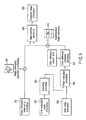
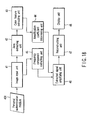
- FIG. 1 schematically shows the overall arrangement of an image processing system according to the first embodiment.
- the image processing system shown in FIG. 1 is applied to, for example, processing of facial images for personal authentication on personal authentication media such as ID cards.
- the image processing system shown in FIG. 1 is comprised of a first image processing apparatus 100 and second image processing apparatus 110.
- the first image processing apparatus 100 records, on a recording medium M, composite image information created by embedding sub-information (sub-image information) in main image information, which is visible to the naked human eye, in an invisible state to the naked human eye.
- the second image processing apparatus 110 restores the embedded sub-information from the composite image information recorded on the recording medium M by the first image processing apparatus 100.
- the first image processing apparatus 100 includes a main image input unit 101, first pre-processing unit 102, second pre-processing unit 103, digital watermark embedding unit 104, post-processing unit 105, and recording unit 106.
- the main image input unit 101 captures a facial image of the holder of a personal authentication medium and converts it into digital image information.
- the main image input unit 101 inputs a facial image of the holder of the personal authentication medium or captures a facial portrait using an image input unit such as a scanner, thereby digitalizing the personal facial image information.
- the main image information (facial image information) has three planes, i.e., R (red), G (green), and B (blue) planes.
- the first pre-processing unit 102 converts the facial image information (to be also referred to as main image information hereinafter) captured by the main image input unit 101 into a form suitable for pixel formation processing by the recording unit 106 (to be described later).
- the second pre-processing unit 103 converts the image information converted by the first pre-processing unit 102 into a form suitable for digital watermark embedding processing.
- the digital watermark embedding unit 104 embeds digital watermark information in the image information converted by the second pre-processing unit 103 by using key information.
- the post-processing unit 105 performs processing inverse to the processing by the second pre-processing 103 for the image information in which the digital watermark is embedded to convert the information back to a form suitable for pixel formation processing by the recording unit 106 (to be described later).
- the recording unit 106 prints/records, on the recording medium M, the composite image information in which the digital watermark is embedded, on the basis of the image information converted by the post-processing unit 105.
- the units ranging from the first pre-processing unit 102 to the post-processing unit 105 embed a digital watermark in main image information and convert it into a form suitable for pixel formation processing by the recording unit 106.
- the flow of these processes will be described with reference to the flowchart shown in FIG. 2 .
- the first pre-processing unit 102 performs the first pre-processing corresponding to pixel formation processing by the recording unit 106 for the main image information captured by the main image input unit 101 to create main image information having undergone the first pre-processing (step S201). In this case, the first pre-processing unit 102 performs thinning-out (invalidation) processing for the main image information.
- the second pre-processing unit 103 performs geometric transformation processing for the main image information having undergone the first pre-processing which is created in step S201, thereby creating image information subjected to embedding (step S202). In this case, the second pre-processing unit 103 performs rotation processing for the main image information having undergone the first pre-processing, and removes pixel portions thinned out in the first pre-processing to compress the effective image size.
- the digital watermark embedding unit 104 performs digital watermark embedding processing for the image information subjected to embedding (main image information having undergone the second pre-processing) created in step S202 (step S203).
- the digital watermark embedding unit 104 creates composite image information by embedding, in image information subjected to embedding, sub-information in an invisible state in which the information cannot be perceived by the human eye.
- the post-processing unit 105 then creates to-be-recorded image information by performing post-processing for the composite image information created in step S203 (step S204).
- the post-processing unit 105 performs reverse rotation processing for the composite image information, and expands the effective image size by adding the pixel portions removed in the second pre-processing.
- digital watermark embedding processing is not limited to R (red), G (green), and B (blue) data.
- color conversion may be performed first, and then digital watermark embedding processing may be performed for data having three planes, i.e., C (C (cyan), M (magenta), and Y (yellow) planes.
- the recording unit 106 prepares a personal authentication medium by printing/recording the to-be-recorded image information created by the post-processing unit 105 on the recording medium M serving as a personal authentication medium. More specifically, the recording unit 106 performs color conversion of R (red), G (green), and B (blue) of the respective pixels of the to-be-recorded image information into C (cyan), M (magenta), and Y (yellow). For example, this color conversion method uses a 3 ⁇ 3 or 3 ⁇ 9 color conversion matrix or LUT (lookUp Table) in accordance with the characteristics of a recording device. The recording unit 106 then generates a driving signal for controlling the recording device from the pieces of C, M, and Y image information.
- the recording unit 106 In the case of the fusion thermal transfer recording scheme, for example, a driving voltage control signal, driving pulse signal, and the like for a thermal head are generated. The recording unit 106 also performs heat control for the thermal head. Finally, the recording unit 106 records the composite image information on the recording medium M by alternately forming even-numbered and odd-numbered pixels in the main scanning direction of the recording device represented by a thermal head on a recording line basis.
- the dots formed on the recording medium M are arrayed as shown in FIG. 3 .
- the respective dots are arranged at a pitch d (1/ ⁇ 2 the pitch of the heating elements of the thermal head) instead of every other dot and are arrayed in a line in a 45° direction.
- FIG. 4 shows an example of a personal authentication medium 401 such as an ID card prepared by the recording unit 106.
- a personal authentication facial image 402 of the holder is recorded on the personal authentication medium 401.
- the facial image 402 is the image created and recorded by the processing described with reference to FIG. 2 .
- personal management information 403 such as an identification number (No.), name, date of birth, and expiration date is recorded on the personal authentication medium 401.
- the personal management information 403 is used as the sub-information in the digital watermark embedding processing in step S203 in FIG. 2 . Consequently, the personal authentication facial image 402 of the personal authentication medium 401 is associated with the personal management information 403. This makes it difficult to partly tamper or counterfeit the personal authentication medium 401, resulting in an improvement in security.
- the second image processing apparatus 110 is comprised of an to-be-recorded image input unit 111, restoring unit 115, and determining unit 114.
- the to-be-recorded image input unit 111 reads/inputs, for example, the composite image information 403 recorded on the personal authentication medium 401 in FIG. 4 , and converts it into digital image information.
- the to-be-recorded image input unit 111 captures the composite image information 403 recorded on the personal authentication medium 401 by using an image input device such as a camera, and converts the information into digital composite image information.
- the image information has three planes, i.e., R (red), G (green), and B (blue) planes, as in the case of the main image input unit 101.
- the restoring unit 115 restores digital watermark information (sub-information) from the composite image information captured by the to-be-recorded image input unit 111.
- the restoring unit 115 is comprised of a frequency component extracting unit 112 and reconstructing unit 113.
- the frequency component extracting unit 112 extracts the spatial frequency component of key information from the composite image information captured by the to-be-recorded image input unit 111.
- the reconstructing unit 113 reconstructs digital watermark information (sub-information) from the spatial frequency component extracted by the frequency component extracting unit 112.
- the reconstructing unit 113 performs totalization processing and spatial filtering for the amplitude information and phase information of the spatial frequency component extracted by the frequency component extracting unit 112, thereby reconstructing a modulated component, i.e., sub-information, with respect to the key information.
- the determining unit 114 determines the authenticity of the personal authentication medium on the basis of the digital watermark information restored by the restoring unit 115.
- the determining unit 114 collates the sub-information (personal management information) restored by the restoring unit 115 with the personal management information 403 on the personal authentication medium 401 which is captured by the to-be-recorded image input unit 111, thereby determining the authenticity of the personal authentication medium 401.
- the fusion thermal transfer recording scheme an image is formed based on the presence/absence of dots.
- the apparent density is controlled by performing area modulation processing of changing the areas of dots.
- the alternate driving/recording scheme is preferably used.
- the above alternate driving/recording scheme is a scheme of alternately driving the odd-numbered heating elements of the odd-numbered lines and the even-numbered heating elements of the even-numbered lines of the recording head (line thermal head) on a recording line basis.
- image information to be recorded is arranged in a lattice pattern, as shown in FIG. 5A .
- the image information is recorded in a staggered pattern to form an image, as shown in FIG. 5B . Therefore, the even-numbered information of each odd-numbered line and the odd-numbered information of each even-numbered line of the image information to be recorded are omitted in actual recording operation.
- the first pre-processing in step S201 and the second pre-processing in step S202 are performed.
- the post-processing in step S204 is performed. This makes it possible to prevent the destruction of the digital watermark in alternate driving/recording operation.
- step S201 image information corresponding to pixels to which no energy is applied in the alternate driving/recording scheme is thinned out.
- FIG. 6A shows an example of the pixel array of the overall image information to be recorded. Referring to FIG. 6A , black portions 601 correspond to pixels to be recorded (information not to be thinned out), and white portions 602 correspond to pixels not to be recorded (information to be thinned out).
- FIG. 6B shows the image information obtained when the image information array shown in FIG. 6A is rotated through 45°.
- the black portions 601 information not to be thinned out
- the white portions 602 information to be thinned out
- the white portions 602 are removed and the resultant information is arrayed again.
- an array of only image information free from the influence of the alternate driving/recording scheme can be created.
- FIG. 7A is a view showing a specific example of image information to be recorded.
- FIG. 7B is a view showing the image information obtained by performing thinning-out processing for the image information shown in FIG. 7A.
- FIG. 7C is a view showing the image information obtained when 45° rotation processing is performed for the image information shown in FIG. 7B.
- FIG. 7D is a view showing the image information obtained when rearrangement processing is performed for the image information shown in FIG. 7C .
- the above thinning-out processing is performed for the image information shown in FIG. 7A .
- the even-numbered information of the odd-numbered lines pixels a12, a14, a32, and a34
- the odd-numbered information of the even-numbered lines pixels a21, a23, a41, and a43
- the image information having undergone the thinning-out processing in the first pre-processing is rotated through 45° (rotation processing).
- the image information shown in FIG. 7B is rotated through 45°, the image information shown in FIG. 7C is formed.
- the effective pixels of the image information shown in FIG. 7C are re-arrayed.
- the remaining information (pixels a11, a13, a22, a24, a31, a33, a42, and a44) after the removal of the portions marked X is effective pixels.
- the effective pixels of the image information shown in FIG. 7C are re-arrayed in the second pre-processing, as shown in FIG. 7D .
- information (0" in this case) which indicates that no information is recorded is stored in each array element as an empty space, as shown in FIG. 7D .
- the thick frame portion is image information to be actually recorded.
- the image information shown in FIG. 7A is compared with the image information shown in FIG. 7D , the area in which the pixels of the image information which is actually recorded or free from the influence of alternate driving/recording are arrayed is reduced. That is, when digital watermark embedding processing is so performed as to make sub-information fall within the thick frame portion in FIG. 7D , the sub-information can be completely held.
- post-processing is processing totally reverse to the first pre-processing and second pre-processing described above.
- the first embodiment has exemplified the fusion thermal transfer recording scheme
- the image processing in the first embodiment can be applied to any recording scheme as long as it realizes gradation expression by dot area modulation of to-be-recorded pixels.
- FIG. 8 schematically shows a processing sequence in this image processing system.
- main image information 801 is, for example, facial image information for personal authentication.
- sub-information 802 is, for example, information for improving the security of the main image information 801 (the numeral "174" in this case).
- Key information 803 is information serving as a key for restoring the sub-information embedded in an invisible state by digital watermark embedding processing.
- image information 804 subjected to embedding is created by performing the first pre-processing and second pre-processing for the main image information 801.
- Digital watermark embedding processing 805 is then performed by using the image information 804 subjected to embedding, sub-information 802, and key information 803 to create digital watermarked image information 806.
- Post-processing is performed as transformation processing inverse to the first pre-processing and second pre-processing to generate composite image information 807.
- a personal authentication medium 809 is completed by executing recording (printing) processing 808 of recording the created composite image information 807.
- a general digital watermark embedding technique can be applied to digital watermark embedding processing in this embodiment.
- the digital watermark embedding processing in this embodiment is especially compatible with a technique of performing digital watermark embedding by superimposing sub-information on main image information.
- the digital watermark embedding techniques that can be applied to this embodiment are disclosed in, for example, Jpn. Pat. Appln. KOKAI Publication Nos. 11-168616 and 2001-268346 . These techniques are described on the premise that main image information is basically a color (full-color) image. By further applying, for example, the technique disclosed in Jpn. Pat. Appln. KOKAI Publication No. 11-355554 to these techniques, sub-information (sub-image information) can be embedded even in a monochrome image.
- FIG. 9 is a view for explaining the flow of digital watermark embedding processing using the color difference modulation scheme described in Jpn. Pat. Appln. KOKAI Publication No. 11-168616 .
- the digital watermark embedding processing sub-information can be embedded in main image information in an invisible state without causing any image deterioration by using the following characteristics (1) to (3).
- the gradation identification ability decreases, and color difference information becomes more difficult to discriminate than luminance information.
- the composite image information (digital watermarked image) generated by this scheme does not depend on the image format for storage. Therefore, as an image format for composite image information, a new future image format can be used as well as a currently available image format such as BMP, TIFF, or JPEG.
- Image information (main image information) 901 subjected to embedding is image information in which to-be-embedded information is embedded.
- the main image information 901 corresponds to a facial portrait (facial image) of the holder of the medium.
- the main image information 901 has, for example, 24-bit information per pixel (eight bits for each of R, G, and B).
- To-be-embedded image information (sub-information) 902 is obtained by converting information to be embedded into a binary image.
- the above sub-information 902 corresponds to the identification number or the like.
- the sub-information 902 has, for example, 1-bit information per pixel.
- Mask image information (key information) 903 is image information used in image combining processing and restoration (reproduction) of embedded image information.
- the key information 903 has 1-bit information per pixel.
- Smoothing processing 904 is performed with each black pixel of the to-be-embedded image information 902 being converted into "1"; and each white pixel, "0".
- the smoothing processing 904 a (3 ⁇ 1)-pixel area including pixels on both ends of a target pixel in the x direction is extracted, and the weighted average of the extracted area is calculated.
- phase modulation processing 905 phase modulation is performed for the mask image information 903 on the basis of the smoothing processing result obtained by the smoothing processing 904.
- Color difference modulation processing 907 is performed using a color difference amount ⁇ Cd on the basis of the phase modulation result obtained by the phase modulation processing 905.
- the color difference modulation processing 907 for example, three components, i.e., R (red), G (green), and B (blue), are separately calculated.
- Composite image information 909 is generated by performing superimposition processing 908 on the basis of the color difference modulation processing result obtained by the color difference modulation processing 907 and the image information 901 subjected to embedding.
- the image information 901 subjected to embedding, to-be-embedded image information 902, and mask image information 903 in FIG. 9 are identical to the main image information 801, sub-information 802, and key information 803 in this embodiment described with reference to FIG. 8 .
- the digital watermark embedding scheme shown in FIG. 9 can therefore be basically applied to this embodiment.
- the array size of effective image information is smaller than the original size of the main image information as indicated by the thick frame in FIG. 7D .
- the composite image information 909 is to be generated by superimposing image information 901' subjected to embedding and superimposition image information 910 obtained by color difference modulation processing, as in the case of digital watermark embedding processing shown in FIG. 9 , the effective portion ("174" in this case) of the superimposition image information 910 needs to completely fall within the hatched portion of the image information 901' subject to embedding.
- the image information 901' subject to embedding, superimposition image information 910, and composite image information 909 are defined as follows:
- each value is an integral value from 0 to 255.
- the composite image information DES C(x, y) is represented as follows by using the image information SRC C(x, y) subject to embedding and superimposition image information STL C(x, y ):
- R red
- G green
- B blue
- C cyan
- M magenta
- Y yellow
- Sub-information restoration processing for the composite image information generated by the above digital watermark embedding processing will be described next. Sub-information is restored by extracting a specific spatial frequency component from the composite image information on the basis of the key information used in embedding processing, and reconstructing the sub-information from the spatial frequency component.
- binary (monochrome) image information formed from a geometric pattern or the like can be used.
- this pattern includes a monochrome checkered pattern formed by unit rectangles each having 1 ⁇ 2 pixels, and a pseudo-random pattern formed on the basis of a predetermined seed.
- a method of extracting a specific spatial frequency component on the basis of key information a method using a spatial frequency filter can be used.
- a coefficient for the spatial frequency filter corresponding to the key information is calculated according to procedures (1) to (4) described below. Note that coefficients may be calculated and stored in advance, or a coefficient may be calculated before the execution of extraction processing or every time extraction processing is performed.
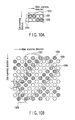
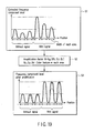
- FIGS. 10A and 10B are schematic views showing an example of the frequency component of the key information.
- a white circle 1001 represents white; and a black circle 1002, black.
- Reference numeral 1003 denotes a fundamental frequency waveform in the main scanning direction; and 1004, a fundamental frequency waveform in the sub-scanning direction.
- a white circle 1005 represents a main color rich dot; and a black circle 1006, a complementary color rich dot. In this case, if the main color is red (R), the complementary color is cyan (C).
- Reference numeral 1007 denotes a fundamental frequency waveform in the main scanning direction; and 1008, a fundamental frequency waveform in the sub-scanning direction.
- the resolution of the main image information is 200 dpi
- the print resolution of the composite image information and the read resolution of the to-be-recorded image input unit 111 are 400 dpi.
- processing (1) described above when embedding processing is performed by using the key information shown in FIG. 10A , composite image information like that shown in FIG. 10B is captured by the to-be-recorded image input unit 111.
- the embedded key information is transformed into a shape 1009 shown in FIG. 10B .
- the fundamental frequency of this information is equal to that of the key information whose size is expanded by an amount corresponding to the ratio between the read resolution and the print resolution. In calculating a filter coefficient, therefore, changes in resolution in recording and reading operations are taken into consideration in advance.
- a frequency filter for extracting the spatial frequency component of the key information from the composite image information is designed.
- a method of extracting a specific spatial frequency component is not limited to the method using the above spatial frequency filter. It suffices to use a method of extracting a specific spatial frequency component by performing mapping information into another space and then inversely mapping the information by using known Fourier transform and Wavelet transform.
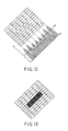
- FIGS. 11 to 13 are schematic views showing the respective processes in reconstruction processing.
- FIG. 11 shows the amplitude of the extracted spatial frequency component of the key information.
- a white portion 101 indicates the + side, and a black portion 1102 indicates the - side.
- FIG. 12 shows the result obtained by projecting the coordinates of points (zero-crossing point s) where the signs "+" and "-" are switched and totalizing the number of points. In this case, coordinates which exhibit a number equal to or more than a predetermined threshold TH are extracted as a zero-crossing point of the reference phase.
- FIG. 13 shows the result obtained by calculating the deviation of the spatial frequency component at each coordinates from the reference phase and replacing the pixel value in accordance with the deviation.
- sub-information can be restored as monochrome binary image information from composite image information.
- Jpn. Pat. Appln. KOKAI Publication No. 2001-268346 is characterized in that a plurality of pieces of key information can be used to embed sub-information (sub-image information), and an arbitrary combination of pieces of key information necessary for the restoration of the sub-information (sub-image information) can be selected.
- the sequence of extracting a spatial frequency component corresponding to key information and reconstructing the sub-information (sub-image information) by binarizing information fragments is executed a predetermined number of times, and the resultant information fragments are combined.
- Nd pieces of key information Ki all the pieces of information (N pieces of key information) used in embedding operation may be set as necessary information, or several pieces of information (Nd (Nd ⁇ N) pieces of information) selected from all the pieces of information according to a predetermined sequence or randomly may be used.
- Sub-information (sub-image information) fragments may be combined by a method of concatenating the respective fragments vertically and horizontally, a method of combining the fragments by addition, exclusive ORing, and the like, or a method of using a combination of arithmetic operations such as concatenation and combining.
- predetermined weights may be assigned to the respective fragments before arithmetic operation.
- the use of the image processing system described above can prepare a personal authentication medium in which a digital watermark is embedded, and check the mark, thereby realizing a system with higher security than the prior art.
- composite image information constituted by main image information and another additional sub-information (sub-image information) embedded in the main image information in an invisible state can be generated for analog data output to an personal authentication medium, and the digital watermark information in the composite image information can be maintained after the composite image information is recorded.
- the digital watermarking technique can be applied to a to-be-recorded image while high gradation performance is maintained.
- the digital watermark information (sub-information) can be stored without being destroyed and restored after recording.
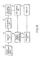
- FIG. 14 shows the arrangement of a second image processing apparatus 110 according to the second embodiment.
- the second image processing apparatus 110 is comprised of an image input unit 11, color component information storage unit 12, color component extracting unit 13, frequency component extracting unit 14, reconstructing unit 15, and display unit 16. The function of each unit will be described in detail below.
- the image input unit 11 captures, for example, composite image information 403 recorded on a personal authentication medium 401 in FIG. 4 using an image input device such as a camera, and converts it into digital composite image information.
- This image information has three planes, i.e., R, G, and B planes.
- the color component information storage unit 12 stores the information of a color component used for the restoration of a digital watermark.
- the color component extracting unit 13 extracts the color component used for the restoration of the digital watermark from the image information input from the image input unit 11 on the basis of the color component information read out from the color component information storage unit 12.
- the reconstructing unit 15 performs totalization processing and spatial filtering for the amplitude information and phase information of the spatial frequency component extracted by the frequency component extracting unit 14 to reconstruct a modulated component, i.e., sub-information, with respect to the key information.
- the display unit 16 displays the sub-information reconstructed by the reconstructing unit 15 (or may simultaneously display the input image information and sub-information).
- the color component information storage unit 12 stores in advance information about a color component exhibiting high gradation characteristics, such as information that can specify a color component exhibiting the highest gradation characteristics among the colors of inks used for printing, e.g., C, M, and Y, or the colors of optical filters used for image capturing, e.g., R, G, and B.
- This information may be a character string indicating a color name, a numerical value indicating the wavelength of an electromagnetic wave corresponding to the color, the number of an address assigned for management in the color component information storage unit 12, or the like.
- a color component exhibiting high gradation characteristics will be described below by taking ink in a printer as an example.
- inks of different colors have different compositions. For this reason, inks of different colors exhibit different physical properties. Gradation characteristics depend on physical properties. As a consequence, inks of different colors differ in gradation characteristics.
- a printer like a sublimation type printer designed to change the density of ink adhering to a print target by controlling the applied energy exhibits characteristics represented by the relationship between the applied energy and the density shown in FIG. 15 .
- the density does not change much in a region where the applied energy is high and a region where the applied energy is low, and the density changes in accordance with the applied energy in an intermediate region.
- Gradation characteristics are determined by the controllability of the density of ink and the feasible density range. With regard to the former, better gradation characteristics appear as the gradient of a plot of applied energy versus density becomes more moderate. With regard to the latter, better gradation characteristics appear as the difference between the minimum density and the maximum density increases.
- FIG. 15 shows the applied energy/density characteristics of three types of ink.
- ink 1 exhibits a narrow feasible density range
- ink 3 exhibits low controllability.
- ink 2 exhibits the best gradation characteristics.
- gradation characteristics described above are not unique to the scheme exemplified above.
- differences in physical property between inks also produce differences in gradation characteristics in a scheme like a fusion type scheme designed to change the areas of dots instead of density.
- the relationship between the restoration of a digital watermark and gradation characteristics will be described next.
- the digital watermark embedded by color difference modulation processing can be restored through a process of color component extraction ⁇ spatial frequency component extraction ⁇ sub-information reconstruction. Since the details of the process have already been described, only its outline will be described.
- a color difference is extracted from a captured image, and the color difference is converted into corresponding information, e.g., bit on/off information, in sub-information reconstruction processing, thereby restoring the digital watermark.
- Information that can be expressed by a color difference depends on gradation characteristics. That is, information that can be expressed decreases in amount as the gradation characteristics decrease, and vice versa.
- the gradation characteristics change for each color component when digital information is converted into analog information or conversion inverse thereto is performed. Using a color component exhibiting the highest gradation characteristics can suppress a decrease in the amount of information that can be expressed by a color difference, thereby improving the restoration characteristics of the digital watermark.
- FIG. 16 shows the arrangement of a second image processing apparatus 110 according to the third embodiment.
- the second image processing apparatus 110 is comprised of an image input unit 21, area extracting unit 22, color feature extracting unit 23, color combining unit 24, frequency component extracting unit 25, reconstructing unit 26, and display unit 27. The function of each unit will be described in detail below.
- the image input unit 21 captures, for example, composite image information 403 recorded on a personal authentication medium 401 in FIG. 4 using an image input device such as a camera, and converts it into digital composite image information.
- This image information has three planes, i.e., R, G, and B planes.
- the area extracting unit 22 sets an area having a predetermined size on the image information input from the image input unit 21.
- the size of an area to be set the number of pixels corresponding to the fundamental wavelength of the spatial frequency component of the key information used in embedding operation is used.
- the color feature extracting unit 23 totalizes the values of pixels existing in the area set by the area extracting unit 22 with respect to each of the R, G, and B planes, and calculates the feature of each color.
- the color combining unit 24 calculates weights used in combining the respective planes, i.e., the R, G, and B planes, on the basis of the totalization result obtained by the color feature extracting unit 23.
- the reconstructing unit 26 performs totalization processing and spatial filtering for the amplitude information and phase information of the spatial frequency component extracted by the frequency component extracting unit 25 to reconstruct a modulated component, i.e., sub-information, with respect to the key information.
- the display unit 27 displays the sub-information reconstructed by the reconstructing unit 26 (or may simultaneously display the input image information and sub-information).
- FIG. 17 shows an outline of the flow of processing in the area extracting unit 22, color feature extracting unit 23, and color combining unit 24.
- the area extracting unit 22 sets an extraction target area S for a color feature, centered on a pixel of interest, on the digital image information captured by the image input unit 21 (step S31).
- the number of pixels corresponding to the fundamental wavelength of the spatial frequency component of the key information used in embedding operation i.e., a value based on the fundamental wavelength which is set in consideration of changes in resolution in recording and reading operations. If, for example, the fundamental wavelength is two pixels and the record and read resolutions for a main image are 200 dpi and 400 dpi, respectively, the size of the area S becomes four pixels. Assume that the pixel of interest is sequentially moved from the left to right and from the bottom to top of the image, and the movement amount corresponds to the size of the area.
- the position of the first pixel of interest is calculated in advance from the placement position of the personal authentication medium at the time of image input operation and the record position of a facial image in the personal authentication medium.
- the color feature in each area S is obtained by using the values of pixels in the area for each plane (step S32).
- a color feature is a numeral value representing a color in the area.
- the average luminance values of pixels in the area for each plane is used as a color feature.
- the color combining unit 24 determines a color combining parameter P C corresponding to the color feature in each plane (step S33), and performs color combining processing for the respective pixels in the area on the basis of the color combining parameter P C (step S34).
- a color combining parameter P C is determined from the color feature, a three-dimensional array in which the color combining parameter P C is stored using the color feature as an index is used.
- Color combining computation is performed for the respective pixels in the area by using the color combining parameters determined in the above manner.
- color combining computation the linear sum obtaining by multiplying the pixel values in the respective planes by the corresponding color combining parameters as weights and adding the resultant values is used.
- the above processing is applied to the overall input image to obtain a color composite image T.
- the frequency component extracting unit 25 extracts a specific spatial frequency component from the color composite image T on the basis of the key information used in digital watermark embedding processing.
- the reconstructing unit 26 reconstructs sub-information.
- the position of the first pixel of interest is determined from the placement position of the personal authentication medium and the record position of the facial image.
- the present invention is not limited to this method.
- a specific pattern is recorded in or near a facial image in advance, and the position of the first pixel of interest may be determined by using the result obtained by detecting the position of the pattern.
- a color feature may be calculated from a predetermined range centered on the pixel of interest.
- a color feature the average luminance of pixels in an area is used.
- a color feature may be a median or mode, or a value indicting a distribution shape, e.g., a value obtained by correction using a standard deviation or variance as a weight.
- a color feature may be a value obtained by applying a predetermined function or algorithm or the like.
- a color combining parameter is determined from a three-dimensional array.
- T ij [R ij , G ij , B ij , P R , P G , P B ] may be set by using a six-dimensional array AT storing color composite values using color features and color combining parameters as indexes.
- the influence of a deterioration is reduced by combining the color components of input image information in this manner, thereby improving the restoration characteristics of the embedded sub-information.
- FIG. 18 shows the arrangement of a second image processing apparatus 110 according to the fourth embodiment.
- the second image processing apparatus 110 is comprised of an image input unit 41, area extracting unit 42, color feature extracting unit 43, amplification coefficient determining unit 44, frequency component extracting unit 45, extracted signal amplifying unit 46, reconstructing unit 47, and display unit 48. The function of each unit will be described in detail below.
- the image input unit 41 captures, for example, composite image information 403 recorded on a personal authentication medium 401 in FIG. 4 using an image input device such as a camera, and converts it into digital composite image information.
- This image information is constituted by three planes, i.e., R, G, and B planes.
- the area extracting unit 42 sets an area having a predetermined size on the image information input from the image input unit 41.
- the size of an area to be set the number of pixels corresponding to the fundamental wavelength of the spatial frequency component of the key information used in embedding operation is used.
- the color feature extracting unit 43 totalizes the values of pixels existing in the area set by the area extracting unit 42 with respect to each of the R, G, and B planes, and calculates the feature of each color.
- the amplification coefficient determining unit 44 determines an amplification coefficient for the reconstruction of a restoration result on the basis of the totalization result obtained by the color feature extracting unit 43.
- the extracted signal amplifying unit 46 performs amplification processing for the amplitude information or phase information of the spatial frequency component extracted by the frequency component extracting unit 45 by using the amplification coefficient determined by the amplification coefficient determining unit 44.
- the reconstructing unit 47 performs totalization processing and spatial filtering for the amplitude information or phase information of the spatial frequency component amplified by the extracted signal amplifying unit 46 to reconstruct a modulated component, i.e., sub-information, with respect to the key information.
- the display unit 48 displays the sub-information reconstructed by the reconstructing unit 47 (or may simultaneously display the input image information and sub-information).
- FIG. 19 shows an outline of the flow of processing in the extracted signal amplifying unit 46.
- the color feature extracting unit 43 calculates a color feature by performing the same processing as that performed by the color feature extracting unit 23 described in the third embodiment (step S51).
- the extracted signal amplifying unit 46 multiplies the spatial frequency component extracted by the frequency component extracting unit 45 by the amplification coefficient M obtained by the amplification coefficient determining unit 44 in each area (step S53). With this processing, the extracted frequency components are corrected such that variations in maximum value in the respective areas fall within a predetermined range.
- f M represents an amplification coefficient computation function for determining an amplification coefficient from a color feature.
- f M represents an amplification coefficient computation function for determining an amplification coefficient from a color feature.
- the visibility of embedded sub-information can be improved by correcting reconstruction processing in accordance with the color components of input image information.
- a multilevel image is created by multiplying an extracted spatial frequency component by an amplification coefficient.
- a binary image may be created by performing binarization processing for the areas using a three-dimensional array A B storing binarization thresholds corresponding to color features in the respective areas. According to this method, the data amount of a restoration result can be reduced, and the contrast of the restoration result can be improved.
- correcting reconstruction processing in accordance with color components of input image information makes it possible to improve the visibility of sub-information restored from printed composite image information without increasing a similar risk.
- an image processing system and image processing method and apparatus which can create composite image information constituted by main image information and another additional sub-information embedded in the main image information in an invisible state for analog data output to a recording medium, and maintain the digital watermark information in the composite image information after the composite image information is recorded.
- an image processing system and image processing method and apparatus which can apply a digital watermarking technique to a to-be-recorded image while maintaining high gradation performance in the fusion thermal transfer recording scheme, and allow the watermark information (sub-information) to be stored and restored without destruction after it is recorded.
- an image processing system and image processing method and apparatus which can restore a digital watermark which is resistant to a deterioration in image information.
- an image processing method and apparatus which can improve restoration characteristics and visibility of embedded sub-information without increasing the risk of disclosing the sub-information.
Landscapes
- Engineering & Computer Science (AREA)
- Multimedia (AREA)
- Signal Processing (AREA)
- Physics & Mathematics (AREA)
- General Physics & Mathematics (AREA)
- Theoretical Computer Science (AREA)
- Fluid Mechanics (AREA)
- Editing Of Facsimile Originals (AREA)
- Image Processing (AREA)
- Cleaning In Electrography (AREA)
- Threshing Machine Elements (AREA)
- Purification Treatments By Anaerobic Or Anaerobic And Aerobic Bacteria Or Animals (AREA)
- Closed-Circuit Television Systems (AREA)
Claims (12)
- Bildverarbeitungssystem mit einer ersten Bildverarbeitungsvorrichtung (100), die angepasst ist zum Aufzeichnen, auf einem Aufzeichnungsmedium (M), von Verbundbildinformation, die erzeugt wird durch Einbetten von unsichtbarer Nebeninformation in sichtbare Hauptbildinformation, und mit einer zweiten Bildverarbeitungsvorrichtung (110), die angepasst ist zum Wiederherstellen der Nebeninformation aus der Verbundbildinformation, die auf dem Aufzeichnungsmedium (M) durch die erste Bildverarbeitungsvorrichtung (100) aufgezeichnet worden ist,
wobei die erste Bildbearbeitungsvorrichtung (100) aufweist:eine Einbettungsverarbeitungseinheit (104), die angepasst ist zum Erzeugen der Verbundbildinformation durch Einbetten von Nebeninformation in Hauptbildinformation in einem unsichtbaren Zustand unter Verwendung der Hauptbildinformation, der Nebenbildinformation und von Schlüsselinformation, die verwendet wird zum Wiederherstellen der Nebeninformation, undeine Aufzeichnungseinheit (106), die angepasst ist zum Aufzeichnen der Verbundbildinformation, die durch die Einbettungsverarbeitungseinheit (104) erzeugt wird, auf einem Aufzeichnungsmedium (M), undwobei die zweite Bildverarbeitungsvorrichtung (100) aufweist:eine Bildeingabeeinheit (111), die angepasst ist zum Eingeben der Verbundbildinformation von dem Aufzeichnungsmedium (M), auf dem die Verbundbildinformation durch die Aufzeichnungseinheit (106) der ersten Bildverarbeitungsvorrichtung (100) aufgezeichnet ist,eine Frequenzkomponentenextrahierungseinheit (112), die angepasst ist zum Extrahieren einer Raumfrequenzkomponente, die für die Schlüsselinformation von der Verbundbildinformation, die durch die Bildeingabeeinheit (111) eingegeben wird, einzigartig ist, undeine Rekonstruktionseinheit (113), die angepasst ist zum Rekonstruieren der Nebeninformation von der Raumfrequenzkomponente, die durch die Frequenzkomponentenextrahierungseinheit (112) extrahiert wird,
dadurch gekennzeichnet, dass die erste Bildverarbeitungsvorrichtung (100) ferner aufweist,eine Vorverarbeitungseinheit (102, 103), die angepasst ist zum Durchführen, für die Hauptbildinformation, einer Vorverarbeitung, die einer Pixelinformationsverarbeitung für ein Bildaufzeichnen in der ersten Bildverarbeitungsvorrichtung (100) entspricht, wobei die Vorverarbeitungseinheit (102) angepasst ist zum Ausdünnen der Hauptbildinformation gemäß der Pixelformationsverarbeitung für das Bildaufzeichnen in der ersten Bildverarbeitungsvorrichtung (100). - Bildverarbeitungssystem nach Anspruch 1, bei dem die erste Bildverarbeitungsvorrichtung (100) ferner aufweist
eine zweite Vorverarbeitungseinheit (103), die angepasst ist zum Durchführen einer geometrischen Transformation bezüglich der Hauptbildinformation, die der Vorverarbeitung durch die Vorverarbeitungseinheit (102) unterzogen worden ist,
eine Inverstransformationseinheit (105), die angepasst ist zum Durchführen einer Transformationsverarbeitung invers zu der Transformationsverarbeitung durch die zweite Vorverarbeitungseinheit (103) bezüglich der Verbundbildinformation, die durch die Einbettungsverarbeitungseinheit (104) erzeugt wird, und wobei
die Aufzeichnungseinheit (106) angepasst ist zum Aufzeichnen der Verbundbildinformation, die der Inverstransformationsverarbeitung durch die Inverstransformationseinheit (105) unterzogen worden ist, durch ein abwechselndes Ansteuerungs/Aufzeichnungs-Schema zum abwechselnden Bilden geradzahliger und ungeradzahliger Pixel in einer Hauptabtastrichtung einer Aufzeichnungsvorrichtung auf einer Aufzeichnungszeilenbasis. - System nach Anspruch 1 oder 2, dadurch gekennzeichnet, dass die zweite Vorverarbeitungseinheit (103) angepasst ist zum Drehen der Hauptbildinformation, die durch die Vorverarbeitungseinheit (102) im Voraus ausgedünnt worden ist, um einen vorbestimmten Winkel und dann zum Durchführen einer geometrischen Transformation zum Entfernen ausgedünnter Bereiche aus der Hauptbildinformation, zum Komprimieren effektiver Bereiche der Hauptbildinformation und zum Durchführen einer Rekonstruktion.
- System nach einem der Ansprüche 1 bis 3, dadurch gekennzeichnet, dass die Frequenzkomponentenextrahierungseinheit (112) angepasst ist zum Extrahieren einer Raumfrequenzkomponente der Schlüsselinformation aus einer durch die Bildeingabeeinheit (111) eingegebenen Verbundbildinformation unter Verwendung eines Frequenzfilterkoeffizienten.
- System nach einem der Ansprüche 1 bis 4, dadurch gekennzeichnet, dass die Rekonstruktionseinheit (113) angepasst ist zum Extrahieren eines Wechselpunkts, bei dem ein Vorzeichen wechselt von der Raumfrequenzkomponente, die durch die Frequenzkomponentenextrahierungseinheit (112) extrahiert worden ist, zum Erhalten einer Referenzphase der Raumfrequenzkomponente durch Projektion des extrahierten Wechselpunkts, zum Berechnen einer Abweichung jeder Koordinate der Raumfrequenzkomponente, die durch die Frequenzkomponentenextrahierungseinheit (112) extrahiert worden ist, aus der erhaltenen Referenzphase, und zum Ersetzen eines Pixelwerts einer Koordinate, die um nicht weniger als einen vorbestimmten Schwellenwert abweicht, durch einen ersten Wert, und jedes der anderen Pixelwerte durch einen zweiten Wert, wodurch die Nebeninformation rekonstruiert wird.
- System nach einem der Ansprüche 1 bis 5, ferner gekennzeichnet durch eine Bestimmungseinheit (114), die angepasst ist zum Bestimmen einer Authentizität des Aufzeichnungsmediums basierend auf der Nebeninformation, die durch die Rekonstruktionseinheit (113) rekonstruiert wird.
- Bildverarbeitungsverfahren zum Aufzeichnen von Verbundbildinformation, die durch Einbetten von unsichtbarer Nebeninformation in sichtbare Hauptbildinformation erzeugt wird, auf einem Aufzeichnungsmedium (M) in einer ersten Bildverarbeitungsvorrichtung (100), und zum Wiederherstellen der Nebeninformation aus der Verbundbildinformation, die auf dem Aufzeichnungsmedium (M) aufgezeichnet ist, in einer zweiten Bildverarbeitungsvorrichtung (110), wobei das Bildverarbeitungsverfahren in einer ersten Bildverarbeitungsvorrichtung (100) aufweist:Erzeugen von Verbundbildinformation durch Einbetten von Nebeninformation in Hauptbildinformation in einem unsichtbaren Zustand unter Verwendung der Hauptbildinformation, der Nebenbildinformation und von Schlüsselinformation, die zur Wiederherstellung der Nebenbildinformation verwendet wird, undAufzeichnen der erzeugten Verbundbildinformation auf einem Aufzeichnungsmedium (M), undEingeben der Verbundbildinformation von dem Aufzeichnungsmedium (M) in eine zweite Bildverarbeitungsvorrichtung (110), und darin:wobei das Bildverarbeitungsverfahren weiter gekennzeichnet ist durchExtrahieren einer Raumfrequenzkomponente, die zu der Schlüsselinformation von der eingegebenen Verbundbildinformation einzigartig ist, undRekonstruieren der Nebeninformation von der extrahierten Raumfrequenzkomponente,eine erste Vorverarbeitung der Hauptbildinformation, in der ersten Bildverarbeitungsvorrichtung (100) entsprechend einer Pixelformationsverarbeitung für ein Bildaufzeichnen in der ersten Bildverarbeitungsvorrichtung (100), wobei die erste Vorverarbeitung die Hauptbildinformation ausdünnt gemäß der Pixelinformationsverarbeitung für das Bildaufzeichnen in der ersten Bildverarbeitungsvorrichtung (100).
- Bildverarbeitungsverfahren nach Anspruch 7, ferner mit
einer zweiten Vorverarbeitung, wobei eine geometrische Transformation bezüglich der Hauptbildinformation, die der ersten Vorverarbeitung unterzogen worden ist, durchgeführt wird,
Durchführen eines Transformationsprozesses invers zu dem Transformationsprozess der zweiten Vorverarbeitung in Bezug auf die Verbundbildinformation, die in dem Erzeugungsschritt erzeugt wird, und
wobei der Aufzeichnungsschritt ein Aufzeichnen der Verbundbildinformation, die der Inverstransformationsverarbeitung unterzogen wird, durch ein abwechselndes Ansteuerungs/Aufzeichnungs-Schema eines abwechselnden Bildens geradzahliger und ungeradzahliger Pixel in einer Hauptabtastrichtung einer Aufzeichnungsvorrichtung auf einer Aufzeichnungszeilenbasis aufweist. - Bildverarbeitungsverfahren nach Anspruch 7 oder 8, wobei die zweite Vorverarbeitung die Hauptbildinformation, die durch die erste Vorverarbeitung im Voraus ausgedünnt worden ist, um einen vorbestimmten Winkel dreht, und dann eine geometrische Transformation durchführt zum Entfernen ausgedünnter Bereiche aus der Hauptbildinformation, effektive Bereiche der Hauptbildinformation komprimiert und eine Rekonstruktion durchführt.
- Bildverarbeitungsverfahren nach einem der Ansprüche 7 bis 9, wobei die Raumfrequenzkoinponente extrahiert wird unter Verwendung eines Frequenzfilterkoeffizienten.
- Bildverarbeitungsverfahren nach einem der Ansprüche 7 bis 10, wobei der Rekonstruktionsschritt aufweist
Extrahieren eines Wechselpunkts, an dem ein Vorzeichen wechselt, aus der extrahierten Raumfrequenzkomponente,
Erhalten einer Frequenzphase der Raumfrequenzkomponente durch Projektion des extrahierten Wechselpunkts,
Berechnen einer Abweichung jeder Koordinate der extrahierten Raumfrequenzkomponente von der erhaltenen Referenzphase, und
Ersetzen eines Pixelwerts einer Koordinate, die um nicht weniger als einen vorbestimmten Schwellenwert abweicht, durch einen ersten Wert, und jeden anderen Pixelwert durch einen zweiten Wert. - Bildverarbeitungsverfahren nach einem der Ansprüche 7 bis 11, wobei die Authentizität des Aufzeichnungsmediums basierend auf der rekonstruierten Nebeninformation bestimmt wird.
Applications Claiming Priority (4)
| Application Number | Priority Date | Filing Date | Title |
|---|---|---|---|
| JP2003122346 | 2003-04-25 | ||
| JP2003122346 | 2003-04-25 | ||
| JP2004075020A JP4227048B2 (ja) | 2003-04-25 | 2004-03-16 | 画像処理システム |
| JP2004075020 | 2004-03-16 |
Publications (3)
| Publication Number | Publication Date |
|---|---|
| EP1471722A2 EP1471722A2 (de) | 2004-10-27 |
| EP1471722A3 EP1471722A3 (de) | 2005-07-06 |
| EP1471722B1 true EP1471722B1 (de) | 2009-04-08 |
Family
ID=32964985
Family Applications (1)
| Application Number | Title | Priority Date | Filing Date |
|---|---|---|---|
| EP04009683A Expired - Lifetime EP1471722B1 (de) | 2003-04-25 | 2004-04-23 | Verfahren und System zur Bildverarbeitung |
Country Status (8)
| Country | Link |
|---|---|
| US (1) | US6883982B2 (de) |
| EP (1) | EP1471722B1 (de) |
| JP (1) | JP4227048B2 (de) |
| KR (1) | KR100605432B1 (de) |
| AT (1) | ATE428263T1 (de) |
| CA (1) | CA2465088A1 (de) |
| DE (1) | DE602004020416D1 (de) |
| TW (1) | TWI280489B (de) |
Families Citing this family (28)
| Publication number | Priority date | Publication date | Assignee | Title |
|---|---|---|---|---|
| US7162035B1 (en) | 2000-05-24 | 2007-01-09 | Tracer Detection Technology Corp. | Authentication method and system |
| KR100878518B1 (ko) * | 2001-12-03 | 2009-01-13 | 삼성전자주식회사 | 워터마크 삽입방법, 전송방법, 복원방법 및 그 장치 |
| JP4167590B2 (ja) * | 2003-12-22 | 2008-10-15 | 株式会社東芝 | 画像処理方法 |
| JP4688797B2 (ja) * | 2004-06-09 | 2011-05-25 | パナソニック株式会社 | コピー制御情報決定装置 |
| US7394567B2 (en) * | 2004-10-21 | 2008-07-01 | Seiko Epson Corporation | Data embedding scheme for duplex color laser printer |
| JP4630765B2 (ja) * | 2005-08-26 | 2011-02-09 | 株式会社東芝 | 画像処理方法および画像処理装置 |
| JP2007104642A (ja) | 2005-09-07 | 2007-04-19 | Toshiba Corp | 画像処理方法、画像処理装置および記録物 |
| US7742619B2 (en) * | 2005-12-21 | 2010-06-22 | Texas Instruments Incorporated | Image watermarking based on sequency and wavelet transforms |
| JP4550749B2 (ja) | 2006-03-07 | 2010-09-22 | 株式会社東芝 | 画像処理方法および画像処理装置 |
| JP2008085875A (ja) * | 2006-09-28 | 2008-04-10 | Toshiba Corp | 画像処理方法および画像処理装置 |
| KR20080049360A (ko) * | 2006-11-30 | 2008-06-04 | 삼성전자주식회사 | 색역 정보 전송방법 및 이를 적용한 영상기기 |
| US8126288B2 (en) * | 2007-01-31 | 2012-02-28 | A School Juridical Person Fujita Educational Institution | Image processing apparatus |
| EP2115694B1 (de) * | 2007-02-05 | 2013-11-27 | NDS Limited | System zur dateneinbettung |
| JP5002392B2 (ja) * | 2007-06-27 | 2012-08-15 | 株式会社東芝 | 画像処理装置および画像処理方法 |
| EP2009897B1 (de) | 2007-06-27 | 2014-12-24 | Kabushiki Kaisha Toshiba | Bildverarbeitungsvorrichtung, Bildverarbeitungsverfahren, Bilderzeugungsvorrichtung, Bilderzeugungsverfahren und aufgezeichnetes Material |
| JP4922205B2 (ja) * | 2007-08-17 | 2012-04-25 | 株式会社東芝 | 画像処理方法および画像処理装置 |
| JP2009088614A (ja) | 2007-09-27 | 2009-04-23 | Toshiba Corp | 画像処理方法および画像処理装置 |
| US7995196B1 (en) | 2008-04-23 | 2011-08-09 | Tracer Detection Technology Corp. | Authentication method and system |
| US8717404B2 (en) | 2010-04-27 | 2014-05-06 | Lifesize Communications, Inc. | Recording a videoconference based on recording configurations |
| US8786667B2 (en) | 2011-04-26 | 2014-07-22 | Lifesize Communications, Inc. | Distributed recording of a videoconference in multiple formats |
| US8780166B2 (en) | 2011-04-26 | 2014-07-15 | Lifesize Communications, Inc. | Collaborative recording of a videoconference using a recording server |
| US8868902B1 (en) * | 2013-07-01 | 2014-10-21 | Cryptite LLC | Characteristically shaped colorgram tokens in mobile transactions |
| US9332309B2 (en) * | 2012-06-08 | 2016-05-03 | Apple Inc. | Sync frame recovery in real time video transmission system |
| WO2013188807A2 (en) * | 2012-06-14 | 2013-12-19 | Digimarc Corporation | Methods and systems for signal processing |
| US10826900B1 (en) * | 2014-12-31 | 2020-11-03 | Morphotrust Usa, Llc | Machine-readable verification of digital identifications |
| US10050796B2 (en) * | 2016-11-09 | 2018-08-14 | Arizona Board Of Regents On Behalf Of Northern Arizona University | Encoding ternary data for PUF environments |
| CN111986127B (zh) * | 2019-05-22 | 2022-03-08 | 腾讯科技(深圳)有限公司 | 一种图像处理方法、装置、计算机设备和存储介质 |
| JP7718197B2 (ja) * | 2021-09-15 | 2025-08-05 | 株式会社リコー | 画像処理装置、読取装置、画像形成装置、および方法 |
Family Cites Families (29)
| Publication number | Priority date | Publication date | Assignee | Title |
|---|---|---|---|---|
| JPH0659739A (ja) | 1992-08-07 | 1994-03-04 | Sumitomo Heavy Ind Ltd | 二重テーブル旋回装置 |
| US5407893A (en) * | 1993-08-19 | 1995-04-18 | Konica Corporation | Material for making identification cards |
| US6345104B1 (en) * | 1994-03-17 | 2002-02-05 | Digimarc Corporation | Digital watermarks and methods for security documents |
| US6614914B1 (en) * | 1995-05-08 | 2003-09-02 | Digimarc Corporation | Watermark embedder and reader |
| US6681029B1 (en) * | 1993-11-18 | 2004-01-20 | Digimarc Corporation | Decoding steganographic messages embedded in media signals |
| JP3224480B2 (ja) * | 1994-09-30 | 2001-10-29 | キヤノン株式会社 | カラー画像処理装置 |
| US5995638A (en) * | 1995-08-28 | 1999-11-30 | Ecole Polytechnique Federale De Lausanne | Methods and apparatus for authentication of documents by using the intensity profile of moire patterns |
| US6095566A (en) * | 1996-03-14 | 2000-08-01 | Kabushiki Kaisha Toshiba | Image recorded product, image recording system, image reproducing system, and recording medium for use to superimpose-record/reproduce additional information |
| JP3547892B2 (ja) | 1996-03-14 | 2004-07-28 | 株式会社東芝 | 画像記録装置及び画像記録方法 |
| US6788347B1 (en) * | 1997-03-12 | 2004-09-07 | Matsushita Electric Industrial Co., Ltd. | HDTV downconversion system |
| US5974150A (en) * | 1997-09-30 | 1999-10-26 | Tracer Detection Technology Corp. | System and method for authentication of goods |
| JPH11168616A (ja) | 1997-12-03 | 1999-06-22 | Toshiba Corp | 画像情報処理方法および画像情報処理装置 |
| JP4015753B2 (ja) | 1998-06-11 | 2007-11-28 | 株式会社東芝 | 画像情報処理方法 |
| EP0921675B1 (de) * | 1997-12-03 | 2006-07-05 | Kabushiki Kaisha Toshiba | Verfahren zur Bildinformationsverarbeitung und Verfahren zur Verhinderung von Fälschungen von Zertifikaten und dergleichen |
| US6519340B1 (en) * | 1998-03-17 | 2003-02-11 | The University Of Connecticut | Method and apparatus for encryption using partial information |
| CA2269651A1 (en) * | 1998-05-12 | 1999-11-12 | Lucent Technologies, Inc. | Transform domain image watermarking method and system |
| US5946414A (en) * | 1998-08-28 | 1999-08-31 | Xerox Corporation | Encoding data in color images using patterned color modulated image regions |
| JP2000182086A (ja) | 1998-12-18 | 2000-06-30 | Toshiba Corp | 券発行方法および券照合方法 |
| US6556688B1 (en) * | 1999-03-15 | 2003-04-29 | Seiko Epson Corporation | Watermarking with random zero-mean patches for printer tracking |
| EP1208537B1 (de) * | 1999-10-26 | 2005-03-02 | Koninklijke Philips Electronics N.V. | Bildverarbeitungsverfahren, -system und-vorrichtung zur rauschverminderung in einer fadenförmigen struktur darstellenden bildsequenz |
| JP4495824B2 (ja) | 2000-03-21 | 2010-07-07 | 株式会社東芝 | 情報処理方法 |
| JP4038956B2 (ja) | 2000-03-23 | 2008-01-30 | 凸版印刷株式会社 | 画像生成システム及び画像生成方法 |
| JP4218920B2 (ja) * | 2000-04-07 | 2009-02-04 | キヤノン株式会社 | 画像処理装置及び画像処理方法並びに記憶媒体 |
| JP4554771B2 (ja) | 2000-06-20 | 2010-09-29 | パナソニック株式会社 | 正当性認証システム、個人証発行システム及び個人証 |
| US7528993B2 (en) * | 2000-11-22 | 2009-05-05 | Concealogram Ltd. | Hiding images in halftone pictures |
| EP1215880A3 (de) * | 2000-12-07 | 2003-08-13 | Sony United Kingdom Limited | Dateneinbettung in Material |
| US6937772B2 (en) * | 2000-12-20 | 2005-08-30 | Eastman Kodak Company | Multiresolution based method for removing noise from digital images |
| JP4828739B2 (ja) * | 2001-08-17 | 2011-11-30 | 株式会社東芝 | 熱転写記録方法、プリンタシステムおよび熱転写記録装置 |
| US6829393B2 (en) * | 2001-09-20 | 2004-12-07 | Peter Allan Jansson | Method, program and apparatus for efficiently removing stray-flux effects by selected-ordinate image processing |
-
2004
- 2004-03-16 JP JP2004075020A patent/JP4227048B2/ja not_active Expired - Fee Related
- 2004-04-12 TW TW093110128A patent/TWI280489B/zh not_active IP Right Cessation
- 2004-04-21 CA CA002465088A patent/CA2465088A1/en not_active Abandoned
- 2004-04-22 KR KR1020040027756A patent/KR100605432B1/ko not_active Expired - Fee Related
- 2004-04-23 AT AT04009683T patent/ATE428263T1/de not_active IP Right Cessation
- 2004-04-23 EP EP04009683A patent/EP1471722B1/de not_active Expired - Lifetime
- 2004-04-23 US US10/830,124 patent/US6883982B2/en not_active Expired - Lifetime
- 2004-04-23 DE DE602004020416T patent/DE602004020416D1/de not_active Expired - Lifetime
Also Published As
| Publication number | Publication date |
|---|---|
| TW200426606A (en) | 2004-12-01 |
| JP2004343712A (ja) | 2004-12-02 |
| ATE428263T1 (de) | 2009-04-15 |
| TWI280489B (en) | 2007-05-01 |
| CA2465088A1 (en) | 2004-10-25 |
| US20040215965A1 (en) | 2004-10-28 |
| JP4227048B2 (ja) | 2009-02-18 |
| KR20040092456A (ko) | 2004-11-03 |
| EP1471722A3 (de) | 2005-07-06 |
| KR100605432B1 (ko) | 2006-07-31 |
| DE602004020416D1 (de) | 2009-05-20 |
| US6883982B2 (en) | 2005-04-26 |
| EP1471722A2 (de) | 2004-10-27 |
Similar Documents
| Publication | Publication Date | Title |
|---|---|---|
| EP1471722B1 (de) | Verfahren und System zur Bildverarbeitung | |
| JP4167590B2 (ja) | 画像処理方法 | |
| US6901862B2 (en) | Image processing method | |
| US20040091050A1 (en) | Digital image watermarking apparatus and method | |
| US8320607B2 (en) | Image processing method and image processing device for embedding invisible sub information into main images | |
| EP1709525A2 (de) | Verbesserte techniken zum erkennen, analysieren und verwenden sichtbarer authentifikationsmuster | |
| EP1808826A2 (de) | Verbesserte Verfahren zur Erkennung, Analyse und Verwendung von sichtbaren Authentifizierungsstrukturen | |
| JP2005159438A (ja) | 画像処理方法 | |
| JP4746663B2 (ja) | 画像処理装置および画像処理方法 | |
| JP4088191B2 (ja) | 画像処理方法および画像記録装置 | |
| JP2004328496A (ja) | 画像処理方法 | |
| JP4686578B2 (ja) | 画像処理方法 | |
| JP2001094755A (ja) | 画像処理方法 | |
| JP3709544B2 (ja) | 印刷物認証方法、印刷物認証システム、識別情報及び可視情報が埋め込まれた印刷物 | |
| CA2545472A1 (en) | Image processing method |
Legal Events
| Date | Code | Title | Description |
|---|---|---|---|
| PUAI | Public reference made under article 153(3) epc to a published international application that has entered the european phase |
Free format text: ORIGINAL CODE: 0009012 |
|
| 17P | Request for examination filed |
Effective date: 20040423 |
|
| AK | Designated contracting states |
Kind code of ref document: A2 Designated state(s): AT BE BG CH CY CZ DE DK EE ES FI FR GB GR HU IE IT LI LU MC NL PL PT RO SE SI SK TR |
|
| AX | Request for extension of the european patent |
Extension state: AL HR LT LV MK |
|
| PUAL | Search report despatched |
Free format text: ORIGINAL CODE: 0009013 |
|
| AK | Designated contracting states |
Kind code of ref document: A3 Designated state(s): AT BE BG CH CY CZ DE DK EE ES FI FR GB GR HU IE IT LI LU MC NL PL PT RO SE SI SK TR |
|
| AX | Request for extension of the european patent |
Extension state: AL HR LT LV MK |
|
| AKX | Designation fees paid |
Designated state(s): AT BE BG CH CY CZ DE DK EE ES FI FR GB GR HU IE IT LI LU MC NL PL PT RO SE SI SK TR |
|
| GRAP | Despatch of communication of intention to grant a patent |
Free format text: ORIGINAL CODE: EPIDOSNIGR1 |
|
| GRAP | Despatch of communication of intention to grant a patent |
Free format text: ORIGINAL CODE: EPIDOSNIGR1 |
|
| GRAS | Grant fee paid |
Free format text: ORIGINAL CODE: EPIDOSNIGR3 |
|
| GRAA | (expected) grant |
Free format text: ORIGINAL CODE: 0009210 |
|
| AK | Designated contracting states |
Kind code of ref document: B1 Designated state(s): AT BE BG CH CY CZ DE DK EE ES FI FR GB GR HU IE IT LI LU MC NL PL PT RO SE SI SK TR |
|
| REG | Reference to a national code |
Ref country code: GB Ref legal event code: FG4D |
|
| REG | Reference to a national code |
Ref country code: CH Ref legal event code: EP |
|
| REG | Reference to a national code |
Ref country code: IE Ref legal event code: FG4D |
|
| REF | Corresponds to: |
Ref document number: 602004020416 Country of ref document: DE Date of ref document: 20090520 Kind code of ref document: P |
|
| PG25 | Lapsed in a contracting state [announced via postgrant information from national office to epo] |
Ref country code: SI Free format text: LAPSE BECAUSE OF FAILURE TO SUBMIT A TRANSLATION OF THE DESCRIPTION OR TO PAY THE FEE WITHIN THE PRESCRIBED TIME-LIMIT Effective date: 20090408 |
|
| NLV1 | Nl: lapsed or annulled due to failure to fulfill the requirements of art. 29p and 29m of the patents act | ||
| PG25 | Lapsed in a contracting state [announced via postgrant information from national office to epo] |
Ref country code: PT Free format text: LAPSE BECAUSE OF FAILURE TO SUBMIT A TRANSLATION OF THE DESCRIPTION OR TO PAY THE FEE WITHIN THE PRESCRIBED TIME-LIMIT Effective date: 20090908 Ref country code: FI Free format text: LAPSE BECAUSE OF FAILURE TO SUBMIT A TRANSLATION OF THE DESCRIPTION OR TO PAY THE FEE WITHIN THE PRESCRIBED TIME-LIMIT Effective date: 20090408 Ref country code: AT Free format text: LAPSE BECAUSE OF FAILURE TO SUBMIT A TRANSLATION OF THE DESCRIPTION OR TO PAY THE FEE WITHIN THE PRESCRIBED TIME-LIMIT Effective date: 20090408 Ref country code: ES Free format text: LAPSE BECAUSE OF FAILURE TO SUBMIT A TRANSLATION OF THE DESCRIPTION OR TO PAY THE FEE WITHIN THE PRESCRIBED TIME-LIMIT Effective date: 20090719 |
|
| PG25 | Lapsed in a contracting state [announced via postgrant information from national office to epo] |
Ref country code: NL Free format text: LAPSE BECAUSE OF FAILURE TO SUBMIT A TRANSLATION OF THE DESCRIPTION OR TO PAY THE FEE WITHIN THE PRESCRIBED TIME-LIMIT Effective date: 20090408 Ref country code: SE Free format text: LAPSE BECAUSE OF FAILURE TO SUBMIT A TRANSLATION OF THE DESCRIPTION OR TO PAY THE FEE WITHIN THE PRESCRIBED TIME-LIMIT Effective date: 20090708 Ref country code: PL Free format text: LAPSE BECAUSE OF FAILURE TO SUBMIT A TRANSLATION OF THE DESCRIPTION OR TO PAY THE FEE WITHIN THE PRESCRIBED TIME-LIMIT Effective date: 20090408 |
|
| REG | Reference to a national code |
Ref country code: CH Ref legal event code: PL |
|
| PG25 | Lapsed in a contracting state [announced via postgrant information from national office to epo] |
Ref country code: DK Free format text: LAPSE BECAUSE OF FAILURE TO SUBMIT A TRANSLATION OF THE DESCRIPTION OR TO PAY THE FEE WITHIN THE PRESCRIBED TIME-LIMIT Effective date: 20090408 Ref country code: RO Free format text: LAPSE BECAUSE OF FAILURE TO SUBMIT A TRANSLATION OF THE DESCRIPTION OR TO PAY THE FEE WITHIN THE PRESCRIBED TIME-LIMIT Effective date: 20090408 Ref country code: LI Free format text: LAPSE BECAUSE OF NON-PAYMENT OF DUE FEES Effective date: 20090430 Ref country code: CZ Free format text: LAPSE BECAUSE OF FAILURE TO SUBMIT A TRANSLATION OF THE DESCRIPTION OR TO PAY THE FEE WITHIN THE PRESCRIBED TIME-LIMIT Effective date: 20090408 Ref country code: EE Free format text: LAPSE BECAUSE OF FAILURE TO SUBMIT A TRANSLATION OF THE DESCRIPTION OR TO PAY THE FEE WITHIN THE PRESCRIBED TIME-LIMIT Effective date: 20090408 Ref country code: CH Free format text: LAPSE BECAUSE OF NON-PAYMENT OF DUE FEES Effective date: 20090430 |
|
| PLBE | No opposition filed within time limit |
Free format text: ORIGINAL CODE: 0009261 |
|
| STAA | Information on the status of an ep patent application or granted ep patent |
Free format text: STATUS: NO OPPOSITION FILED WITHIN TIME LIMIT |
|
| PG25 | Lapsed in a contracting state [announced via postgrant information from national office to epo] |
Ref country code: SK Free format text: LAPSE BECAUSE OF FAILURE TO SUBMIT A TRANSLATION OF THE DESCRIPTION OR TO PAY THE FEE WITHIN THE PRESCRIBED TIME-LIMIT Effective date: 20090408 Ref country code: BE Free format text: LAPSE BECAUSE OF FAILURE TO SUBMIT A TRANSLATION OF THE DESCRIPTION OR TO PAY THE FEE WITHIN THE PRESCRIBED TIME-LIMIT Effective date: 20090408 |
|
| 26N | No opposition filed |
Effective date: 20100111 |
|
| GBPC | Gb: european patent ceased through non-payment of renewal fee |
Effective date: 20090708 |
|
| PG25 | Lapsed in a contracting state [announced via postgrant information from national office to epo] |
Ref country code: BG Free format text: LAPSE BECAUSE OF FAILURE TO SUBMIT A TRANSLATION OF THE DESCRIPTION OR TO PAY THE FEE WITHIN THE PRESCRIBED TIME-LIMIT Effective date: 20090708 |
|
| PG25 | Lapsed in a contracting state [announced via postgrant information from national office to epo] |
Ref country code: MC Free format text: LAPSE BECAUSE OF NON-PAYMENT OF DUE FEES Effective date: 20090430 Ref country code: IE Free format text: LAPSE BECAUSE OF NON-PAYMENT OF DUE FEES Effective date: 20090423 |
|
| PG25 | Lapsed in a contracting state [announced via postgrant information from national office to epo] |
Ref country code: GB Free format text: LAPSE BECAUSE OF NON-PAYMENT OF DUE FEES Effective date: 20090708 |
|
| PG25 | Lapsed in a contracting state [announced via postgrant information from national office to epo] |
Ref country code: GR Free format text: LAPSE BECAUSE OF FAILURE TO SUBMIT A TRANSLATION OF THE DESCRIPTION OR TO PAY THE FEE WITHIN THE PRESCRIBED TIME-LIMIT Effective date: 20090709 |
|
| PG25 | Lapsed in a contracting state [announced via postgrant information from national office to epo] |
Ref country code: IT Free format text: LAPSE BECAUSE OF FAILURE TO SUBMIT A TRANSLATION OF THE DESCRIPTION OR TO PAY THE FEE WITHIN THE PRESCRIBED TIME-LIMIT Effective date: 20090408 |
|
| PG25 | Lapsed in a contracting state [announced via postgrant information from national office to epo] |
Ref country code: LU Free format text: LAPSE BECAUSE OF NON-PAYMENT OF DUE FEES Effective date: 20090423 |
|
| PG25 | Lapsed in a contracting state [announced via postgrant information from national office to epo] |
Ref country code: HU Free format text: LAPSE BECAUSE OF FAILURE TO SUBMIT A TRANSLATION OF THE DESCRIPTION OR TO PAY THE FEE WITHIN THE PRESCRIBED TIME-LIMIT Effective date: 20091009 |
|
| PG25 | Lapsed in a contracting state [announced via postgrant information from national office to epo] |
Ref country code: TR Free format text: LAPSE BECAUSE OF FAILURE TO SUBMIT A TRANSLATION OF THE DESCRIPTION OR TO PAY THE FEE WITHIN THE PRESCRIBED TIME-LIMIT Effective date: 20090408 |
|
| PG25 | Lapsed in a contracting state [announced via postgrant information from national office to epo] |
Ref country code: CY Free format text: LAPSE BECAUSE OF FAILURE TO SUBMIT A TRANSLATION OF THE DESCRIPTION OR TO PAY THE FEE WITHIN THE PRESCRIBED TIME-LIMIT Effective date: 20090408 |
|
| REG | Reference to a national code |
Ref country code: FR Ref legal event code: PLFP Year of fee payment: 13 |
|
| REG | Reference to a national code |
Ref country code: FR Ref legal event code: PLFP Year of fee payment: 14 |
|
| REG | Reference to a national code |
Ref country code: FR Ref legal event code: PLFP Year of fee payment: 15 |
|
| PGFP | Annual fee paid to national office [announced via postgrant information from national office to epo] |
Ref country code: FR Payment date: 20220308 Year of fee payment: 19 |
|
| PGFP | Annual fee paid to national office [announced via postgrant information from national office to epo] |
Ref country code: DE Payment date: 20220302 Year of fee payment: 19 |
|
| REG | Reference to a national code |
Ref country code: DE Ref legal event code: R119 Ref document number: 602004020416 Country of ref document: DE |
|
| PG25 | Lapsed in a contracting state [announced via postgrant information from national office to epo] |
Ref country code: FR Free format text: LAPSE BECAUSE OF NON-PAYMENT OF DUE FEES Effective date: 20230430 Ref country code: DE Free format text: LAPSE BECAUSE OF NON-PAYMENT OF DUE FEES Effective date: 20231103 |