EP1471326A1 - Gasdruckschalter für eine Zünd- und Sicherungseinrichtung einer Munition - Google Patents
Gasdruckschalter für eine Zünd- und Sicherungseinrichtung einer Munition Download PDFInfo
- Publication number
- EP1471326A1 EP1471326A1 EP04002749A EP04002749A EP1471326A1 EP 1471326 A1 EP1471326 A1 EP 1471326A1 EP 04002749 A EP04002749 A EP 04002749A EP 04002749 A EP04002749 A EP 04002749A EP 1471326 A1 EP1471326 A1 EP 1471326A1
- Authority
- EP
- European Patent Office
- Prior art keywords
- gas pressure
- pressure switch
- switching piston
- contact
- switch according
- Prior art date
- Legal status (The legal status is an assumption and is not a legal conclusion. Google has not performed a legal analysis and makes no representation as to the accuracy of the status listed.)
- Granted
Links
- 239000012528 membrane Substances 0.000 claims abstract description 10
- 239000007789 gas Substances 0.000 claims description 68
- 238000007789 sealing Methods 0.000 claims description 15
- 239000003380 propellant Substances 0.000 claims description 7
- 239000000919 ceramic Substances 0.000 claims description 6
- 238000013016 damping Methods 0.000 claims description 6
- 239000004033 plastic Substances 0.000 claims description 4
- 229920003023 plastic Polymers 0.000 claims description 4
- 238000006073 displacement reaction Methods 0.000 claims description 3
- 239000000463 material Substances 0.000 claims description 3
- ATJFFYVFTNAWJD-UHFFFAOYSA-N Tin Chemical compound [Sn] ATJFFYVFTNAWJD-UHFFFAOYSA-N 0.000 claims description 2
- 239000011521 glass Substances 0.000 claims description 2
- 239000012811 non-conductive material Substances 0.000 claims 2
- RYGMFSIKBFXOCR-UHFFFAOYSA-N Copper Chemical compound [Cu] RYGMFSIKBFXOCR-UHFFFAOYSA-N 0.000 description 2
- 239000011248 coating agent Substances 0.000 description 2
- 238000000576 coating method Methods 0.000 description 2
- 229910052802 copper Inorganic materials 0.000 description 2
- 239000010949 copper Substances 0.000 description 2
- 238000005553 drilling Methods 0.000 description 2
- 230000007246 mechanism Effects 0.000 description 2
- 230000001133 acceleration Effects 0.000 description 1
- 239000000853 adhesive Substances 0.000 description 1
- 230000001070 adhesive effect Effects 0.000 description 1
- 230000001419 dependent effect Effects 0.000 description 1
- 238000002474 experimental method Methods 0.000 description 1
- 239000002360 explosive Substances 0.000 description 1
- 210000003746 feather Anatomy 0.000 description 1
- 238000009434 installation Methods 0.000 description 1
- 239000011810 insulating material Substances 0.000 description 1
- 238000002955 isolation Methods 0.000 description 1
- 238000000034 method Methods 0.000 description 1
- ORQBXQOJMQIAOY-UHFFFAOYSA-N nobelium Chemical compound [No] ORQBXQOJMQIAOY-UHFFFAOYSA-N 0.000 description 1
- 239000000565 sealant Substances 0.000 description 1
- 238000000926 separation method Methods 0.000 description 1
- 229910001220 stainless steel Inorganic materials 0.000 description 1
- 239000010935 stainless steel Substances 0.000 description 1
Images




Classifications
-
- F—MECHANICAL ENGINEERING; LIGHTING; HEATING; WEAPONS; BLASTING
- F42—AMMUNITION; BLASTING
- F42C—AMMUNITION FUZES; ARMING OR SAFETY MEANS THEREFOR
- F42C19/00—Details of fuzes
- F42C19/06—Electric contact parts specially adapted for use with electric fuzes
-
- F—MECHANICAL ENGINEERING; LIGHTING; HEATING; WEAPONS; BLASTING
- F42—AMMUNITION; BLASTING
- F42B—EXPLOSIVE CHARGES, e.g. FOR BLASTING, FIREWORKS, AMMUNITION
- F42B3/00—Blasting cartridges, i.e. case and explosive
- F42B3/006—Explosive bolts; Explosive actuators
-
- F—MECHANICAL ENGINEERING; LIGHTING; HEATING; WEAPONS; BLASTING
- F42—AMMUNITION; BLASTING
- F42C—AMMUNITION FUZES; ARMING OR SAFETY MEANS THEREFOR
- F42C15/00—Arming-means in fuzes; Safety means for preventing premature detonation of fuzes or charges
- F42C15/28—Arming-means in fuzes; Safety means for preventing premature detonation of fuzes or charges operated by flow of fluent material, e.g. shot, fluids
- F42C15/30—Arming-means in fuzes; Safety means for preventing premature detonation of fuzes or charges operated by flow of fluent material, e.g. shot, fluids of propellant gases, i.e. derived from propulsive charge or rocket motor
-
- H—ELECTRICITY
- H01—ELECTRIC ELEMENTS
- H01H—ELECTRIC SWITCHES; RELAYS; SELECTORS; EMERGENCY PROTECTIVE DEVICES
- H01H35/00—Switches operated by change of a physical condition
- H01H35/24—Switches operated by change of fluid pressure, by fluid pressure waves, or by change of fluid flow
Definitions
- the invention relates to a gas pressure switch for an ignition and safety device an ammunition according to the features specified in the preamble of claim 1.
- Ignition and safety devices (ZUSE) of ammunition are required to release Ignition circuits two physically independent release mechanisms.
- ZUSE safety devices
- the launch acceleration and the Missile swirl used.
- smooth-tube ammunition for example 120 mm HE ammunition, however, a spin-dependent release mechanism cannot be used.
- the invention is essentially based on the idea that the gas pressure switch to execute an assembly which is designed as a "once" switching element and preferably in the form of a screw that slants from the back into the The back of a corresponding ammunition can be screwed in.
- the gas pressure switch comprises a switching piston which can be displaced in the direction of the longitudinal axis of the switch, which is arranged in its rest position by a perpendicular to the longitudinal axis of the switch Locking pin is secured against unintentional movement.
- This locking pin is designed and arranged in such a way that the switching piston, if necessary occurring transport loads and rough handling of the ammunition cannot be damaged or moved.
- the locking pin is on the cargo space facing side preferably of a membrane made of a plastic Material that is welded to the housing of the gas pressure switch sealed.
- the switching piston closes with its lower end two contacts that transmit a signal to release the ignition.
- the plastically deformable Diaphragm also causes the switching piston to be held in its contact position is so that the contacts remain securely closed afterwards.
- Switches are a functional separation between sealing and switching. Through the Forming the hat-shaped membrane remains in the "upturned” state and hereby locks the switching piston. It is also not a feather or another Element required to ensure the switched state.
- the gas pressure switch therefore does not need to contain any plastics, sealants or adhesives, so that one very long shelf life is given with full functional reliability.
- the gas pressure switch according to the invention represents a crucial securing element for the ignition and safety system of a projectile.
- a predetermined pressure e.g. 345 bar
- the switching function only takes place when exceeded this defined pressure.
- the switch is then closed and remains until the explosive charge is ignited -closed without bouncing- securely.
- FIG. 1 illustrates the installation of a gas pressure switch 1 according to the invention in the rear Area of a smooth tube storey, preferably HE storey 114, wherein the gas pressure switch 1 has the shape of a hexagon screw.
- This hexagon screw 1 is screwed via a thread 14 into a bore in the tailgate 17 and the screw receptacle is sealed by means of a sealing ring 22.
- the propellant charge of the projectile 114 is in a manner known per se Propellant charge sleeve 18. Since the floor shown here is a wing-stabilized Projectile acts, are on the tailgate 17 hinged tail wings 19 arranged.
- the projectile 114 shown in Figure 1 is within a gun barrel, not shown guided by means of a guide band 20 attached to the floor 114.
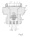
- the gas pressure switch 1 (FIGS. 2 and 3) comprises a housing 100 Stainless steel, which is designed like a hexagon screw in its outer shape.
- a cylindrical bore 2 is arranged, which leads to the upper End is designed as a conical depression 3 and opposite one in the Bore 2 guided switching piston 6, a corresponding one in the area of the depression 3 Has conical surface 3 ', forms a sealing seat with the sealing surfaces 3 and 3'.
- an additional ring-shaped between the sealing surfaces 3 and 3 ' Damping element 101 made of a plastic material (e.g. tin or lead) be arranged.
- the housing 100 At the lower end of the housing 100 there is a cylindrical bore 2 Carrier 4 with insulated contact pins 5, the carrier 4 being screwed into the housing 100 and is welded from the outside.
- the housing 100 of the gas pressure switch 1 is provided on the outside with a fine thread 14 in the lower area, with the help of this the gas pressure switch 1 screwed into the floor 114 and by means of the metallic Sealing ring 22 (Fig.1) is sealed.
- the switching piston 6 is on the upper side of a hat-shaped, plastically deformable and hat-shaped membrane 8 welded to the switch housing 100 surrounded and is connected on its underside to a contact device 60 which consists essentially of a pin-shaped element 11, which is is a ceramic insert with gold-plated contact surfaces 10. That on the shift piston 6 pin-shaped element 11 arranged in an electrically insulated manner is in the region 13 by means of a retaining ring 12 (which is attached to the switching piston using laser light, for example 6 is welded).
- the switching piston is in its rest position shown in FIG held a shearable locking pin 7.
- the gold-plated contact points of the ceramic insert arranged on the switching piston 6 11 and the contact pins 5 guarantee a flawless transfer function of the signal.
- gas pressure switch 1 is gas-tight is when it pressures up to 6,500 bar up to 15 milliseconds becomes. It has proven to be useful if not only the carrier 4 in the area 15, but also the metallic membrane 8 with the housing 100 in the area 16 are welded.
- FIGS. 5 and 6 show a second embodiment of a gas pressure switch according to the invention, which is essentially different from the gas pressure switch shown in FIGS. 2 and 3 differs in that the contact device designated 60 ' does not consist of a ceramic insert with metallized contact surfaces, but of a metallic switching pin 102, which is connected to a plunger 102 '.
- the pestle 102 ' is formed by a holding device 103 located in the switching piston 6 insulating material, preferably glass.
- the switching pin 102 has one Diameter and a shape that are chosen so that it is in the contact position of the switching piston 6 (Fig.6) in the contact pins 5 "clawed".
- the gas pressure switch according to the invention shown in FIGS. 7 and 8 also distinguishes compared to the gas pressure switch shown in Figures 2 and 3 essentially through the contact device labeled 60 " this exemplary embodiment by an adjoining the switching piston 6 on the underside separate assembly, the switching piston 6 when moving from its Rest position (Fig. 7) in its contact position (Fig. 8) via a flat one Bottom 105 causes a displacement of the contact device 60 ".
- the contact device 60 "consists of a printed circuit board arrangement of four axially contiguous circuit boards 106-109. The first, the housing-fixed Contact pins 5 facing printed circuit board 106 centering the contact pins 5 cause.
- the second circuit board 107 adjoining the first circuit board 106 is provided with holes 110 which are arranged above the contact pins 5 and in the rest position of the switching piston 6 ( Figure 7) compared to the diameter of the Contact pins 5 have a smaller diameter.
- a third printed circuit board 108 connects to the second printed circuit board 107, which also two sleeve-shaped metallic receptacles 104 is provided, which have a copper coating 115 are electrically connected to each other.
- the location is the two receptacles 104 in the third circuit board 108 selected such that in the event of a shift of the switching piston 6 from its rest position into its contact position contact pins 5 fixed to the housing each in one of the two sleeve-shaped receptacles 104 are pressed.
- a fourth circuit board 109 At the top of the third circuit board 108 is a fourth circuit board 109, which on the face 105 of the switching piston 6 and on the face 112 of the third circuit board 108 abuts movement of the circuit board assembly 60 "in the rest position of the switching piston 6 (Fig. 7) to prevent.
- the invention is of course not based on the exemplary embodiments described above limited.
- the contacts fixed to the housing cannot only rigid, but also spring-elastic connected to the housing 100 of the gas pressure switch his.
Landscapes
- Engineering & Computer Science (AREA)
- General Engineering & Computer Science (AREA)
- Chemical & Material Sciences (AREA)
- Combustion & Propulsion (AREA)
- Switches Operated By Changes In Physical Conditions (AREA)
- Emergency Lowering Means (AREA)
Abstract
Description
- 1
- Gasdruckschalter, Sechskantschraube
- 2
- Bohrung
- 3
- kegelförmige Senkung, Dichtfläche
- 3'
- Kegelfläche, Dichtfläche
- 4
- Träger
- 5
- Kontaktstift
- 6
- Schaltkolben
- 7
- Sicherungsstift
- 8
- Membrane
- 9
- Stirnfläche
- 10
- Kontaktfläche
- 11
- Stiftförmiges Element, Keramikeinsatz
- 12
- Haltering
- 13
- Bereich
- 14
- Gewinde
- 15
- Bereich
- 16
- Bereich
- 17
- Geschoßheck
- 18
- Treibladungshülse
- 19
- Leitwerksflügel
- 20
- Führungsband
- 21
- Spitze
- 22
- Dichtring
- 60,60'
- Kontakteinrichtung
- 60"
- Kontakteinrichtung, Leiterplattenanordnung
- 100
- Gehäuse
- 101
- Dämpfungselement
- 102
- stiftförmige Element, Schaltstift
- 102'
- Stößel
- 103
- Halteeinrichtung
- 104
- hülsenförmige Aufnahme
- 105
- Unterseite, Stirnseite (Schaltkolben)
- 106
- erste Leiterplatte
- 107
- zweite Leiterplatte
- 108
- dritte Leiterplatte
- 109
- vierte Leiterplatte
- 110
- Bohrung
- 112
- Stirnseite (dritte Leiterplatte)
- 114
- Geschoß
- 115
- Kupferbeschichtung
Claims (17)
- Gasdruckschalter für eine Zünd- und Sicherungseinrichtung einer Munition mit einem Gehäuse (100) und einem bei seiner bestimmungsgemäßen Anwendung durch die Treibladungsgase der Munition von einer Ruhestellung in eine Kontaktstellung verschiebbaren Schaltkolben (6), der auf seiner den Treibladungsgasen abgewandten Seite auf eine Kontakteinrichtung (60-60") wirkt, die in der Kontaktstellung des Schaltkolbens (6) mindestens zwei gehäusefeste Kontaktstifte (5) elektrisch leitend miteinander verbindet, dadurch gekennzeichnet, daß der Gasdruckschalter (1) einen abscherbaren Sicherungsstift (7) umfaßt, der den Schaltkolben (6) bis zum Erreichen eines vorgegeben Gasdruckes in seiner Ruhestellung hält und bei Erreichen des definierten Gasdruckes abschert, so daß der Schaltkolben (6) dann in seine Kontaktstellung verschiebbar ist.
- Gasdruckschalter nach Anspruch 1, dadurch gekennzeichnet, daß der Schaltkolben (6) auf seiner den Treibladungsgasen zugewandten Außenseite von einer plastisch verformbaren und mit dem Gehäuse (100) des Gasdruckschalters (1) verbundenen Membrane (8) umgeben ist, die nach Erreichen eines vorgegebenen Gasdruckes gegen den Schaltkolben (6) drückt und den Schaltkolben (6) nach Erreichen seiner Kontaktstellung in dieser Stellung hält.
- Gasdruckschalter nach einem der Ansprüche 1 oder 2, dadurch gekennzeichnet, daß der Schaltkolben (6) und das Gehäuse (100) des Gasdruckschalters (1) Dichtflächen (3; 3') aufweisen, welche sich bei der Verschiebung des Schaltkolbens (6) von der Ruhestellung in die Kontaktstellung aufeinander zu bewegen.
- Gasdruckschalter nach Anspruch 3, dadurch gekennzeichnet, daß der Schaltkolben (6) und das Gehäuse (100) des Gasdruckschalters (1) zur Abdichtung kegelige Dichtflächen (3; 3') aufweisen.
- Gasdruckschalter nach Anspruch 3 oder 4, dadurch gekennzeichnet, daß zwischen den Dichtflächen (3; 3') des Schaltkolbens (6) und des Gehäuses (100) ein ringförmiges Dämpfungselement (101) aus einem plastischen Material angeordnet ist.
- Gasdruckschalter nach Anspruch 4, dadurch gekennzeichnet, daß das Dämpfungselement (101) aus Zinn oder Blei besteht.
- Gasdruckschalter nach einem der Ansprüche 1 bis 6, dadurch gekennzeichnet, daß die Kontakteinrichtung (60; 60') ein stiftförmiges Element (11; 102) umfaßt, welches bei der Verschiebung des Schaltkolbens (6) von seiner Ruhe- in seine Kontaktstellung zwischen die beiden gehäusefesten Kontaktstifte (5) gedrückt wird und diese elektrisch miteinander verbindet.
- Gasdruckschalter nach Anspruch 7, dadurch gekennzeichnet, daß es sich bei dem stiftförmigen Element (11) der Kontakteinrichtung (60) um einen Keramikeinsatz mit vorzugsweise vergoldeten Kontaktflächen handelt.
- Gasdruckschalter nach Anspruch 7, dadurch gekennzeichnet, daß der Keramikeinsatz (11) fest mit dem Schaltkolben (6) verbunden ist.
- Gasdruckschalter nach Anspruch 7, dadurch gekennzeichnet, daß es sich bei dem stiftförmigen Element (102) der Kontakteinrichtung (60') um einen metallischen Schaltstift handelt, der direkt oder über einen Stößel (102') aus einem elektrisch nicht leitenden Material von einer in dem Schaltkolben (6) angeordneten Halteeinrichtung (103) aus einem elektrisch nicht leitenden Material gehalten wird.
- Gasdruckschalter nach Anspruch 9, dadurch gekennzeichnet, daß die Halteeinrichtung (103) des Schaltstiftes (102) aus Glas besteht.
- Gasdruckschalter nach einem der Ansprüche 1 bis 6, dadurch gekennzeichnet, daß die Kontakteinrichtung (60") aus einer Leiterplattenanordnung besteht, die zwei elektrisch leitend miteinander verbundene hülsenförmige Aufnahmen (104) umfaßt, derart, daß bei der Verschiebung des Schaltkolbens (6) von seiner Ruhein seine Kontaktstellung die beiden gehäusefesten Kontaktstifte (5) jeweils in eine der hülsenförmigen Aufnahmen (104) gedrückt werden.
- Gasdruckschalter nach Anspruch 12, dadurch gekennzeichnet, daß es sich bei der Leiterplattenanordnung (60") um eine an den Schaltkolben (6) anschließende separate Baugruppe handelt, wobei der Schaltkolben (6) bei seiner Verschiebung über seine plan ausgebildete Unterseite (105) eine entsprechende Verschiebung der Leiterplattenanordnung (60") bewirkt.
- Gasdruckschalter nach Anspruch 12 oder 13, dadurch gekennzeichnet, daß die Leiterplattenanordnung (60") aus mindestens vier sich axial aneinander anschließenden Leiterplatten (106-109) besteht, einer ersten, den gehäusefesten Kontaktstiften (5) zugewandten Leiterplatte (106), welche eine Zentrierung der Kontaktstifte (5) bewirkt, einer zweiten Leiterplatte (107) mit Bohrungen (110), die einen gegenüber dem Durchmesser der Kontaktstifte (5) kleineren Durchmesser aufweisen, um eine Kontaktierung der hülsenförmigen Aufnahmen (104) mit den Kontaktstiften (5) in der Ruhestellung des Schaltkolbens (6) zu verhindern, einer dritten Leiterplatte (108) mit den hülsenförmigen Aufnahmen (104) und einer vierten Leiterplatte (109), die an den Stirnseiten (105, 112) des Schaltkolbens (6) und der dritten Leiterplatte (108) anliegt, um eine Bewegung der Leiterplattenanordnung (60") in der Ruhestellung des Schaltkolbens (6) zu verhindern.
- Gasdruckschalter nach einem der Ansprüche 1 bis 14, dadurch gekennzeichnet, daß die Kontaktstifte (5) an den Kontaktstellen der dem Schaltkolben (6) zugeordneten Kontakteinrichtung (60-60 ") vergoldete Spitzen (21) aufweisen.
- Gasdruckschalter nach einem der Ansprüche 1 bis 15, dadurch gekennzeichnet, daß die Kontaktstifte (5) in einem Träger (4) isoliert angeordnet sind und der Träger (4) mit dem Gehäuse (100) des Gasdruckschalters (1) über ein Gewinde verbunden und gasdicht verschweißt ist.
- Gasdruckschalter nach einem der Ansprüche 1 bis 6, gekennzeichnet durch eine Bauart in Form einer Schraube, die von der Rückseite schräg in ein Geschoßheck (17) einschraubbar ist.
Applications Claiming Priority (4)
| Application Number | Priority Date | Filing Date | Title |
|---|---|---|---|
| DE10319265 | 2003-04-26 | ||
| DE10319265 | 2003-04-26 | ||
| DE10354012A DE10354012B4 (de) | 2003-04-26 | 2003-11-19 | Gasdruckschalter für eine Zünd- und Sicherungseinrichtung einer Munition |
| DE10354012 | 2003-11-19 |
Publications (2)
| Publication Number | Publication Date |
|---|---|
| EP1471326A1 true EP1471326A1 (de) | 2004-10-27 |
| EP1471326B1 EP1471326B1 (de) | 2010-04-07 |
Family
ID=32963541
Family Applications (1)
| Application Number | Title | Priority Date | Filing Date |
|---|---|---|---|
| EP04002749A Expired - Lifetime EP1471326B1 (de) | 2003-04-26 | 2004-02-07 | Gasdruckschalter für eine Zünd- und Sicherungseinrichtung einer Munition |
Country Status (5)
| Country | Link |
|---|---|
| US (1) | US7150228B2 (de) |
| EP (1) | EP1471326B1 (de) |
| JP (1) | JP4541747B2 (de) |
| IL (1) | IL161577A (de) |
| NO (1) | NO329475B1 (de) |
Families Citing this family (7)
| Publication number | Priority date | Publication date | Assignee | Title |
|---|---|---|---|---|
| US8239699B2 (en) * | 2009-06-26 | 2012-08-07 | Intel Corporation | Method and apparatus for performing energy-efficient network packet processing in a multi processor core system |
| KR101473897B1 (ko) * | 2013-04-26 | 2014-12-17 | 이노크린 주식회사 | 비폭발성 고체 또는 액체를 이용한 폭발물 |
| US9470498B1 (en) * | 2014-09-05 | 2016-10-18 | The United States Of America As Represented By The Secretary Of The Army | High pressure isolated latching safety switch device |
| US10510504B2 (en) * | 2017-12-08 | 2019-12-17 | Eagle Technology, Llc | Force amplified low pressure depth activated switch |
| CN114508975B (zh) * | 2022-02-15 | 2023-10-13 | 南京理工大学 | 降低剪切断面摩擦影响的引信刚性保险惯性运动机构 |
| US12272844B1 (en) | 2023-05-10 | 2025-04-08 | The United States Of America As Represented By The Secretary Of The Army | Pressure activated battery system |
| CN118712033B (zh) * | 2024-09-02 | 2024-11-22 | 浙江通佐电力科技有限公司 | 一种环保柜用组合开关 |
Citations (7)
| Publication number | Priority date | Publication date | Assignee | Title |
|---|---|---|---|---|
| US2674946A (en) * | 1950-06-14 | 1954-04-13 | Bofors Ab | Control device for an electric circuit |
| US2721913A (en) * | 1950-07-17 | 1955-10-25 | Jr Raymond C Kent | Shock and static pressure discriminating switch |
| FR79714E (fr) * | 1959-11-06 | 1963-01-11 | Soc Tech De Rech Ind | Perfectionnements à l'amorçage électrique des projectiles à charge creuse |
| FR1417132A (fr) * | 1964-04-14 | 1965-11-12 | Charbonnages De France | Nouveau dispositif de court-circuitage de conducteurs électriques |
| US3275770A (en) * | 1965-02-26 | 1966-09-27 | Sinclair Research Inc | Explosion pressure responsive switch |
| FR2070544A5 (de) * | 1969-12-09 | 1971-09-10 | Serat | |
| US3698323A (en) * | 1955-12-23 | 1972-10-17 | Us Army | Explosive operated switch for bomb fuzing system |
Family Cites Families (19)
| Publication number | Priority date | Publication date | Assignee | Title |
|---|---|---|---|---|
| US2458478A (en) | 1943-04-10 | 1949-01-04 | Riehard L Maneval | Setback switch |
| US2873681A (en) | 1945-02-03 | 1959-02-17 | Charles C Lauritsen | Fuze |
| US2931874A (en) * | 1953-10-08 | 1960-04-05 | Audley B Leaman | Explosive switch |
| US3167018A (en) | 1962-03-19 | 1965-01-26 | Aeronca Mfg Corp | Missile safety and arming circuit |
| US3248504A (en) | 1962-10-08 | 1966-04-26 | Atlas Chem Ind | Connecting switch |
| US3155800A (en) * | 1963-01-02 | 1964-11-03 | Genisco Technology Corp | Single action temperature sensitive electrical switch including camming means for a plunger retaining member |
| US3500279A (en) | 1968-07-26 | 1970-03-10 | Us Navy | Exploding bridgewire operated switch |
| US3601057A (en) * | 1969-02-11 | 1971-08-24 | Gibbs Mfg And Research Corp | Arming switch |
| US3675579A (en) * | 1970-02-25 | 1972-07-11 | Us Navy | Pressure actuated safety and arming device |
| US3991649A (en) * | 1975-06-27 | 1976-11-16 | Networks Electronic Corporation | Pyrotechnic wire cutter |
| US4150266A (en) | 1977-01-27 | 1979-04-17 | Networks Electronic Corp. | Miniature pyrotechnic squib switch, single pole, normally open |
| DE2755322A1 (de) | 1977-12-12 | 1979-06-13 | Dynamit Nobel Ag | Elektrischer schalter mit wenigstens einem polpaar |
| JPS573000A (en) * | 1980-06-06 | 1982-01-08 | Mitsubishi Electric Corp | Flying object |
| US4339638A (en) * | 1980-10-15 | 1982-07-13 | Mcdonnell Douglas Corporation | Electrical switch |
| US4527025A (en) | 1983-02-02 | 1985-07-02 | Networks Electronic Corp. | Miniature delay switch |
| US4852494A (en) * | 1987-11-16 | 1989-08-01 | Williams Robert A | Explosively actuated switch |
| FR2633385B1 (fr) | 1988-06-23 | 1990-08-31 | France Etat Armement | Systeme de securite et d'armement pour projectile utilisant la pression des gaz de combustion |
| FR2679697B1 (fr) | 1991-07-25 | 1994-05-20 | Giat Industries | Contacteur electrique a commande pyrotechnique. |
| US5131328A (en) * | 1991-12-13 | 1992-07-21 | The United States Of America As Represented By The Secretary Of The Navy | Safety and arming system for tube launched projectile |
-
2004
- 2004-02-07 EP EP04002749A patent/EP1471326B1/de not_active Expired - Lifetime
- 2004-03-09 NO NO20041025A patent/NO329475B1/no not_active IP Right Cessation
- 2004-04-16 JP JP2004121492A patent/JP4541747B2/ja not_active Expired - Fee Related
- 2004-04-22 US US10/829,278 patent/US7150228B2/en not_active Expired - Lifetime
- 2004-04-22 IL IL161577A patent/IL161577A/en active IP Right Grant
Patent Citations (7)
| Publication number | Priority date | Publication date | Assignee | Title |
|---|---|---|---|---|
| US2674946A (en) * | 1950-06-14 | 1954-04-13 | Bofors Ab | Control device for an electric circuit |
| US2721913A (en) * | 1950-07-17 | 1955-10-25 | Jr Raymond C Kent | Shock and static pressure discriminating switch |
| US3698323A (en) * | 1955-12-23 | 1972-10-17 | Us Army | Explosive operated switch for bomb fuzing system |
| FR79714E (fr) * | 1959-11-06 | 1963-01-11 | Soc Tech De Rech Ind | Perfectionnements à l'amorçage électrique des projectiles à charge creuse |
| FR1417132A (fr) * | 1964-04-14 | 1965-11-12 | Charbonnages De France | Nouveau dispositif de court-circuitage de conducteurs électriques |
| US3275770A (en) * | 1965-02-26 | 1966-09-27 | Sinclair Research Inc | Explosion pressure responsive switch |
| FR2070544A5 (de) * | 1969-12-09 | 1971-09-10 | Serat |
Also Published As
| Publication number | Publication date |
|---|---|
| JP2004325067A (ja) | 2004-11-18 |
| US7150228B2 (en) | 2006-12-19 |
| US20050188877A1 (en) | 2005-09-01 |
| NO20041025L (no) | 2004-10-27 |
| IL161577A0 (en) | 2004-09-27 |
| NO329475B1 (no) | 2010-10-25 |
| JP4541747B2 (ja) | 2010-09-08 |
| IL161577A (en) | 2008-11-03 |
| EP1471326B1 (de) | 2010-04-07 |
Similar Documents
| Publication | Publication Date | Title |
|---|---|---|
| DE2443793A1 (de) | Kombiniertes anzuendhuetchen | |
| DE2907309C2 (de) | Aus einem Geschoß auszustoßendes Tochtergeschoß | |
| EP1471326B1 (de) | Gasdruckschalter für eine Zünd- und Sicherungseinrichtung einer Munition | |
| DE2227104A1 (de) | Geschoss oder rakete mit aufklappbarem leitwerk | |
| EP1347262A2 (de) | Antriebseinheit für grosskalibrige Munition | |
| EP0088260A1 (de) | Unterwasser-Zünder | |
| EP1623184A2 (de) | Schnellfeuerwaffe | |
| DE10354012B4 (de) | Gasdruckschalter für eine Zünd- und Sicherungseinrichtung einer Munition | |
| EP3767223B1 (de) | System, insbesondere handgranate | |
| DE1578084A1 (de) | Kopplungsglied zum Verbinden eines Flugkoerpers mit einer Abschuss- und Lenkeinrichtung | |
| CH674078A5 (de) | ||
| EP0731331B1 (de) | Abschussvorrichtung für selbstangetriebene Flugkörper, insbesondere Artillerieraketen | |
| DE2932921C2 (de) | Kontaktkopf für aus elektrisch betätigbaren Wurfbechern verschießbare Wurfkörper | |
| DE68904827T2 (de) | Sicherheits- und schaerfungssystem fuer ein den druck der verbrennungsgase benutzendes geschoss. | |
| DE3534309A1 (de) | Aufschlagschalter fuer zuender | |
| EP0104138A2 (de) | Vorrichtung zum Sichern und Schärfen eines elektrisch zündbaren Munitionskörpers | |
| EP2872850B1 (de) | Granate, insbesondere 40-mm-granate | |
| DE19926753C2 (de) | Sicherheitseinrichtungen für Munitionen sowie Munition mit einer solchen Sicherheitseinrichtung | |
| EP1853872B1 (de) | Munition, insbesondere programmierbare grosskalibrige munition | |
| DE2946156C2 (de) | ||
| EP1357349B1 (de) | Patrone | |
| EP0267407B1 (de) | Sicherungseinrichtung für einen Zünder eines Gefechtskopfes | |
| DE10001886B4 (de) | Aus einer Rohrwaffe verschießbares Geschoss mit einem durch Treibladungsgase beaufschlagten, auf eine den Zünder aktivierende Einrichtung einwirkenden Übertragungselement | |
| EP0129679A1 (de) | Abstandszündeinrichtung für ein Geschoss | |
| DE2842882B2 (de) | Aufschlagzünder mit einer Zündkapsel |
Legal Events
| Date | Code | Title | Description |
|---|---|---|---|
| PUAI | Public reference made under article 153(3) epc to a published international application that has entered the european phase |
Free format text: ORIGINAL CODE: 0009012 |
|
| AK | Designated contracting states |
Kind code of ref document: A1 Designated state(s): AT BE BG CH CY CZ DE DK EE ES FI FR GB GR HU IE IT LI LU MC NL PT RO SE SI SK TR |
|
| AX | Request for extension of the european patent |
Extension state: AL LT LV MK |
|
| 17P | Request for examination filed |
Effective date: 20041009 |
|
| AKX | Designation fees paid |
Designated state(s): CH DE FR GB LI |
|
| RAP1 | Party data changed (applicant data changed or rights of an application transferred) |
Owner name: RHEINMETALL WAFFE MUNITION GMBH |
|
| 17Q | First examination report despatched |
Effective date: 20070524 |
|
| RAP1 | Party data changed (applicant data changed or rights of an application transferred) |
Owner name: RHEINMETALL WAFFE MUNITION GMBH |
|
| GRAP | Despatch of communication of intention to grant a patent |
Free format text: ORIGINAL CODE: EPIDOSNIGR1 |
|
| GRAS | Grant fee paid |
Free format text: ORIGINAL CODE: EPIDOSNIGR3 |
|
| GRAA | (expected) grant |
Free format text: ORIGINAL CODE: 0009210 |
|
| AK | Designated contracting states |
Kind code of ref document: B1 Designated state(s): CH DE FR GB LI |
|
| REG | Reference to a national code |
Ref country code: GB Ref legal event code: FG4D Free format text: NOT ENGLISH |
|
| REG | Reference to a national code |
Ref country code: CH Ref legal event code: EP |
|
| REG | Reference to a national code |
Ref country code: CH Ref legal event code: NV Representative=s name: E. BLUM & CO. AG PATENT- UND MARKENANWAELTE VSP |
|
| REF | Corresponds to: |
Ref document number: 502004010986 Country of ref document: DE Date of ref document: 20100520 Kind code of ref document: P |
|
| PLBE | No opposition filed within time limit |
Free format text: ORIGINAL CODE: 0009261 |
|
| STAA | Information on the status of an ep patent application or granted ep patent |
Free format text: STATUS: NO OPPOSITION FILED WITHIN TIME LIMIT |
|
| 26N | No opposition filed |
Effective date: 20110110 |
|
| REG | Reference to a national code |
Ref country code: FR Ref legal event code: PLFP Year of fee payment: 13 |
|
| REG | Reference to a national code |
Ref country code: FR Ref legal event code: PLFP Year of fee payment: 14 |
|
| REG | Reference to a national code |
Ref country code: FR Ref legal event code: PLFP Year of fee payment: 15 |
|
| PGFP | Annual fee paid to national office [announced via postgrant information from national office to epo] |
Ref country code: FR Payment date: 20210224 Year of fee payment: 18 Ref country code: CH Payment date: 20210217 Year of fee payment: 18 |
|
| PGFP | Annual fee paid to national office [announced via postgrant information from national office to epo] |
Ref country code: GB Payment date: 20210219 Year of fee payment: 18 Ref country code: DE Payment date: 20210217 Year of fee payment: 18 |
|
| REG | Reference to a national code |
Ref country code: DE Ref legal event code: R119 Ref document number: 502004010986 Country of ref document: DE |
|
| REG | Reference to a national code |
Ref country code: CH Ref legal event code: PL |
|
| GBPC | Gb: european patent ceased through non-payment of renewal fee |
Effective date: 20220207 |
|
| PG25 | Lapsed in a contracting state [announced via postgrant information from national office to epo] |
Ref country code: FR Free format text: LAPSE BECAUSE OF NON-PAYMENT OF DUE FEES Effective date: 20220228 |
|
| PG25 | Lapsed in a contracting state [announced via postgrant information from national office to epo] |
Ref country code: LI Free format text: LAPSE BECAUSE OF NON-PAYMENT OF DUE FEES Effective date: 20220228 Ref country code: GB Free format text: LAPSE BECAUSE OF NON-PAYMENT OF DUE FEES Effective date: 20220207 Ref country code: DE Free format text: LAPSE BECAUSE OF NON-PAYMENT OF DUE FEES Effective date: 20220901 Ref country code: CH Free format text: LAPSE BECAUSE OF NON-PAYMENT OF DUE FEES Effective date: 20220228 |