EP1471029A1 - Vorrichtung mit bewegbarer Türdichtung für einen verschiebbaren Türflügel einer Aufzugsanlage und Aufzugsanlage mit einer solchen Vorrichtung - Google Patents
Vorrichtung mit bewegbarer Türdichtung für einen verschiebbaren Türflügel einer Aufzugsanlage und Aufzugsanlage mit einer solchen Vorrichtung Download PDFInfo
- Publication number
- EP1471029A1 EP1471029A1 EP04008390A EP04008390A EP1471029A1 EP 1471029 A1 EP1471029 A1 EP 1471029A1 EP 04008390 A EP04008390 A EP 04008390A EP 04008390 A EP04008390 A EP 04008390A EP 1471029 A1 EP1471029 A1 EP 1471029A1
- Authority
- EP
- European Patent Office
- Prior art keywords
- door
- seal
- sealing
- door seal
- coupling mechanism
- Prior art date
- Legal status (The legal status is an assumption and is not a legal conclusion. Google has not performed a legal analysis and makes no representation as to the accuracy of the status listed.)
- Granted
Links
- 230000033001 locomotion Effects 0.000 claims description 76
- 238000007789 sealing Methods 0.000 claims description 64
- 230000007246 mechanism Effects 0.000 claims description 47
- 230000008878 coupling Effects 0.000 claims description 43
- 238000010168 coupling process Methods 0.000 claims description 43
- 238000005859 coupling reaction Methods 0.000 claims description 43
- 238000006073 displacement reaction Methods 0.000 claims description 8
- 238000009434 installation Methods 0.000 claims description 7
- 230000007480 spreading Effects 0.000 description 4
- 238000004891 communication Methods 0.000 description 3
- 239000000567 combustion gas Substances 0.000 description 2
- 230000001419 dependent effect Effects 0.000 description 2
- 238000011161 development Methods 0.000 description 2
- 230000018109 developmental process Effects 0.000 description 2
- 239000000463 material Substances 0.000 description 2
- 239000000725 suspension Substances 0.000 description 2
- 241001295925 Gegenes Species 0.000 description 1
- WHGYBXFWUBPSRW-FOUAGVGXSA-N beta-cyclodextrin Chemical compound OC[C@H]([C@H]([C@@H]([C@H]1O)O)O[C@H]2O[C@@H]([C@@H](O[C@H]3O[C@H](CO)[C@H]([C@@H]([C@H]3O)O)O[C@H]3O[C@H](CO)[C@H]([C@@H]([C@H]3O)O)O[C@H]3O[C@H](CO)[C@H]([C@@H]([C@H]3O)O)O[C@H]3O[C@H](CO)[C@H]([C@@H]([C@H]3O)O)O3)[C@H](O)[C@H]2O)CO)O[C@@H]1O[C@H]1[C@H](O)[C@@H](O)[C@@H]3O[C@@H]1CO WHGYBXFWUBPSRW-FOUAGVGXSA-N 0.000 description 1
- 238000006243 chemical reaction Methods 0.000 description 1
- 150000001875 compounds Chemical class 0.000 description 1
- 230000000694 effects Effects 0.000 description 1
- 239000003546 flue gas Substances 0.000 description 1
- 239000006260 foam Substances 0.000 description 1
- 230000003993 interaction Effects 0.000 description 1
- 239000006249 magnetic particle Substances 0.000 description 1
- 239000002184 metal Substances 0.000 description 1
- 238000000926 separation method Methods 0.000 description 1
- 239000000779 smoke Substances 0.000 description 1
Images


Classifications
-
- B—PERFORMING OPERATIONS; TRANSPORTING
- B66—HOISTING; LIFTING; HAULING
- B66B—ELEVATORS; ESCALATORS OR MOVING WALKWAYS
- B66B13/00—Doors, gates, or other apparatus controlling access to, or exit from, cages or lift well landings
- B66B13/30—Constructional features of doors or gates
- B66B13/308—Details of seals and joints
-
- B—PERFORMING OPERATIONS; TRANSPORTING
- B66—HOISTING; LIFTING; HAULING
- B66B—ELEVATORS; ESCALATORS OR MOVING WALKWAYS
- B66B13/00—Doors, gates, or other apparatus controlling access to, or exit from, cages or lift well landings
- B66B13/30—Constructional features of doors or gates
Definitions
- the invention relates to a device with movable Door seal for a sliding door leaf Elevator installation and an elevator installation with such Contraption.
- the elevator shaft has landing doors with at least a horizontally movable shaft door wing.
- At the Elevator car is a cabin door with at least a horizontally movable cabin door wing.
- the Cabin door moves together with the elevator car in the shaft.
- One of the shaft doors and the cabin door may only open automatically when the Elevator car reached a floor to be approached.
- the landing doors All other floors must be closed stay.
- the elevator system therefore has a coupling device on which an unlocking mechanism of the Shaft door and the cabin door are coupled so that during normal operation of the elevator system the shaft door one floor and the cabin door open only when the Elevator car in the area of the corresponding floor stops.
- One in European Patent EP 0 332 841 B1 described elevator system has a coupling device which links the landing doors to the cabin door, that unlocking the shaft door from the car door is possible.
- Each manhole door has two manhole door take-up rollers, in the following as landing door rollers designated.
- the shaft door rollers are designed and arranged that the landing door rollers along with a Shaft door wing against a closing force transverse to the direction of travel the elevator car are displaced.
- the elevator car is one for each cabin door wing Driver unit associated, which is essentially two symmetrically arranged skid units, which is extend in the direction of travel of the elevator car. The skid units are displaceable transversely to the direction of travel.
- the skid units perform a partial movement which, for example, is used around the cabin door sash to unlock mechanically. Through this partial movement can also be done the unlocking of the landing door wing. After unlocking the skid units lead a common Horizontal movement out, here as opening movement referred to as. Through this opening movement open the Cabin door leaves the wings of the shaft door.
- sealing lips Between the cabin door wings and the elevator cabin as well between the landing door wings and the landing door frame arise door gaps caused by sealing lips or the like be sealed. It is a disadvantage of these sealing lips, that they open and close the door Grind along a sealing surface. This grinding leads first, wear of the sealing lips, and secondly can cause annoying noises by grinding become. Worn sealing lips fulfill their sealing function no longer satisfactory. This makes it special on high-performance lifts that move very fast too disturbing air currents in the elevator car or in the Shaft door area come. In addition, disturbing noises enter the elevator car.
- the door seals should be designed on the shaft doors so that they penetrate delay of combustion gases into the elevator shaft or even prevent.
- a sealing system for a cabin door is in the European Patent EP 616 970 B1.
- Elevator cabin proposed, the cabin door wings along a rail are guided, the inclined sealing surfaces having.
- Each cabin door wing is with an angle profile provided, which also has an inclined surface.
- Will the Cabin door leaves closed, so the inclined approach Areas of the angle profiles the inclined sealing surfaces. are closed the cabin door leaves, so are this area on each other and serve as a seal.
- This arrangement is consuming.
- a sanding of the surfaces can be done with this Solution can not be prevented.
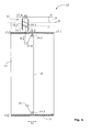
- Fig. 1 shows a first device 10 according to the invention in a schematic side view.
- the device 10 has two movable door seals 17.1, 17.2 on, by a sliding door 11 are supported.
- the device 10 is part of an elevator car that is part of a Elevator system with a lift shaft and landing doors is.
- the door leaf 11 has a carriage, which has a plate 7 with rollers 9 includes. This carriage moves along a rail 8, which is mechanically attached to the elevator car is attached.
- This suspension allows a horizontal Opening and closing movement D1 of the car door leaf 11.
- the movable door seals 17.1, 17.2 are arranged so that the door leaf 11 in the closed state at least in an area through the door seals 17.1, 17.2 in relation on a sealing surface on the elevator car (not in FIG.
- the device 10 comprises a Driver unit 12, which on the plate 7 of the door 11th is attached.
- This driver unit 12 has, for example two runners 12.1 and 12.2, which are parallel to each other run and a lever system 13.1, 13.2 together in Connection stand.
- This movement is referred to here as partial movement A1.
- the Part movement A1 is controlled by a rotation of the lever Lever system 13.1, 13.2 generated by a car door drive or a dedicated drive unit is moved.
- the device 10 has a coupling mechanism on, the driver unit 12 mechanically with the door seals 17.1, 17.2 connects.
- the coupling mechanism a cable-like mechanism, the via a roller 14.1 or a lever with the lever system 13.1, 13.2 is related.
- On the roll 14.1 is a Rope 16 attached, that, caused by the partial movement A1, performs a movement B1.
- the rope 16 is over a first guide roller 14.5, a second guide roller 14.2 and a third guide roller 14.3 out.
- At the end of the rope 15 is Rope 16 connected to the door leaf 11.
- the role is 14.2 mechanically with the upper door seal 17.1 and the role 14.3 mechanically connected to the lower door seal 17.2.
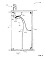
- Fig. 2 shows a second device 20 according to the invention in a schematic side view.
- the device 20 has three movable door seals 17.1, 17.2 and 17.3, the carried by a horizontally movable door 11 become.
- the movable door seals 17.1, 17.2 and 17.3 are arranged so that the door 11 in the closed Condition at least in one area through the door seals 17.1, 17.2 and 17.3 with respect to corresponding sealing surfaces (not shown in Fig. 2) sealed to the elevator car is.
- the device 20 comprises a driver unit 12, which is fastened above the door leaf 11 to a plate 7 is.
- This driver unit 12 has, for example, two runners 12.1 and 12.2, which run parallel to each other and via a lever system 13.1, 13.2 in conjunction.
- partial movement A1 The partial movement is through generates a rotation of the lever of the lever system 13.1, 13.2, that of a cabin door drive or one specifically for that existing drive unit is moved.
- the device 20 has a coupling mechanism on, the driver unit 12 mechanically with the door seals 17.1, 17.2 and 17.3 connects.
- the coupling mechanism is as well as in Fig. 1, a cable-like designed mechanism that has a role of 14.1 or one Lever with the lever system 13.1, 13.2 is in communication.
- a rope 16 is attached, which, caused performs a movement B1 through the partial movement A1.
- the Rope 16 is via a first guide roller 14.5, a second Guide roller 14.2, a third guide roller 14.4 and a fourth guide roller 14.3 out.
- At the end of the rope 15 is the rope 16 connected to the door leaf 11.
- the role is 14.2 mechanically with the upper door seal 17.1, the roller 14.4 mechanically with the side door seal 17.3 and the roller 14.3 mechanically connected to the lower door seal 17.2.
- moving apart (partial movement A1) of the runners 12.1, 12.2 is pulled on the rope 16.
- This moves the upper seal 17.1 down, the side seal 17.3 to the left and bottom seal 17.2 upwards.
- the movement the seals 17.1, 17.2 and 17.3 is indicated by the arrows C1, C2 and C3 indicated.
- All three seals 17.1, 17.2 and 17.3 perform translatory movements.
- the seals 17.1, 17.2 and 17.3 are stored and managed accordingly, to allow a translatory movement.
- To guide the Seals 17.1, 17.2, 17.3 are, for example, parallel displacement guides suitable.
- FIGS. 3A and 3B A detail of a third embodiment of the invention is indicated in FIGS. 3A and 3B.
- This device also comprises a driver unit 12 with two skids 12.1 and 12.2 and a lever system 13.1, 13.2.
- a coupling mechanism is provided which mechanically connects the driver unit 12 to a door seal 17.1.
- the coupling mechanism is designed like a cable and is directly connected to the lever 13.1 of the lever system in connection. This connection is provided outside the pivot point of the lever 13.1.
- a guide pulley 14.5 was attached to the door (not shown).
- the rope end is fastened to a fastening element 18.
- the fastening element 18 is connected to the seal 17.1.
- the movable door seal 17.1 has two return elements 19, which may comprise springs, for example.
- Each of the springs 19 presses the seal 17.1 with a force F against the sealing surface 21, which is indicated in Fig. 3A as a line.
- FIG. 3A shows a section of FIG. 3A.
- the cable 16 pulls with a force B1 on the seal 17.1 and brings them thereby in an open position.
- the force B1 is at least twice as large as the force F.
- the springs 19 are compressed and there is a small gap (air gap) between the sealing surface 21 and the seal 17.1.
- a fourth device 30, according to the invention, is in the Fig. 4 shown.
- Fig. 4 shows the device 30 in a schematic side view.
- the device 30 has a movable door seal 37 on, which is a sliding Door (not shown) is worn.
- the door seal 37 includes a seal carrier 37.2, which is a sealing profile 37.1 wearing.
- the door seal 37 is arranged so that the Door leaf closed at least in one Area through the door seal 37 with respect to a sealing surface on the housing of the elevator car (not shown in Fig. 4) is sealed.
- the device 30 comprises a driver unit 35, which is above the door leaf on the plate of a the door-carrying trolley is attached.
- the driver unit 35 has two runners 35.1 and 35.2, which run parallel to each other. In each of the runners 35.1 and 35.2 a Tastkufe 32.4 or 32.5 is integrated.
- the Runners 35.1 and 35.2 powered by a cabin door drive or a dedicated drive unit, a (spreading) movement. This will be the Trailed skids 32.4, 32.5 with shaft door rollers 39.1 and 39.2 in Brought in contact.
- These shaft door rollers 39.1 and 39.2 are associated with shaft door wings and exert a drag the feeler skids 32.4, 32.5.
- the movement of the touch skids 32.4, 32.5 is here referred to as partial movement A1.
- the scooters 32.4, 32.5 are connected to a lever system 33.1, 33.2, that the partial movement A1 in a lifting / lowering movement B1 of the Area 34 implements.
- a coupling mechanism which is the driver unit 35 connects mechanically with a door seal 37.
- the coupling mechanism is designed as a Bowden cable 36, being over the Bowden cable 36 and a lever mechanism 38th a tensile force on the door seal 37 is exercisable.
- the Bowden cable 36 is a straight element represented, which transmits a compressive force.
- the Bowden cable 36 is flexible and can pressure and tensile forces transferred and laid along a curved path become.
- the Bowden cable 36 a flexible sheath 36.2 and a flexible, elongated element 36.1. The elongated element 36.1 can be moved up and down without the shell 36.2 shifts.
- lever mechanism 38 which has two lever elements 38.1 and 38.2.
- the lever 38.1 is rotatably mounted about an axis 38.3.
- the lever element 38.2 is movable over an axis 38.4 with the Lever element 38.1 connected.
- the coupling mechanism works as follows. if the Runners 32.5 and 32.4 perform a partial movement A1, the directed towards each other, the point 34 rises. As a result, the elongated element 36.1 is pushed upwards and the lever member 38.1 is raised on the left side. This rotational movement of the lever member 38.1 is connected to D1 characterized. The right side of the lever member 38.1 is lowered and thereby pulls the lever element 38.2 after below. Since the lever element 38.2 with the seal carrier 37.2 is connected, thereby the entire seal 37 after moved down. The seal 37 is thus in the open position brought.
- Fig. 5 shows a fifth device 40 according to the invention in a schematic side view.
- the device 40 has three movable door seals 47.1, 47.2 and 47.3, the carried by a horizontally movable door 41 become.
- the movable door seals 47.1, 47.2 and 47.3 are arranged so that the door 41 in the closed Condition at least in one area through the door seals 47.1, 47.2 and 47.3 with respect to corresponding sealing surfaces (not shown in Fig. 5) sealed to the elevator car is.
- the device 40 comprises a driver unit 42, the above the door 41 at the plate of the Door wing carrying carriage is attached.
- This driver unit 42 has, for example, two runners, the parallel to each other and via a lever system in Connection stand.
- the Part movement A1 is controlled by a rotation of the lever Lever system produced by a cabin door operator or moved a specially existing drive unit becomes.
- the device 40 has a coupling mechanism 46 on which the driver unit 42 mechanically with the door seals 47.1, 47.2 and 47.3 connects.
- the embodiment shown is in the Coupling mechanism 46 around a bowdenzugartig laid out Mechanism via a rod 43 or a lever with the Lever system of driver unit 42 is in communication.
- the rod 43 leads a downward movement B1.
- the rod 43 is at one point 48.2 connected to a lever arm 48.1.
- the lever arm 48.1 is rotatably mounted about an axis 48.3 and on the lever arm 48.1 are the ends of three Bowden cables 46.1 to 46.3 attached.
- the sheaths of the three Bowden cables 46.1 to 46.3 are held in a holder 48.4.
- the Bowden cable 46.1 is mechanical with the upper door seal 47.1, the Bowden cable 46.2 mechanically with the side door gasket 47.3 and the Bowden cable 46.3 mechanically with the lower door seal 47.2 connected.
- the lever arm 48.1 turns against clockwise about axis 48.3, and it will become one Traction on the Bowden cables 46.1, 46.2, 46.3 exercised.
- the upper seal 47.1 moves downward, the lateral seal 47.3 to the left and lower seal 47.2 up.
- the movement of the seals 47.1, 47.2 and 47.3 is indicated by the arrows C1, C2 and C3.
- All three Gaskets 47.1, 47.2 and 47.3 perform translational Movements and are stored and managed accordingly.
- To guide the seals 47.1, 47.2, 47.3 are, for example Parallel displacement guides suitable.
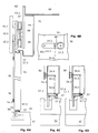
- FIGS. 6A to 6D are Sections through the door front of an elevator car shown.
- FIG. 6A shows a car door panel 51.
- the cabin door panel 51 has a carriage, which has a plate 67 with rollers 69 includes.
- This carriage moves along a rail 68, which is mechanically connected to the elevator car 66 is attached.
- This suspension allows a horizontal Opening and closing movement of the car door leaf 51 in a plane perpendicular to the plane of the drawing.
- the car door panel 51 At the bottom is the car door panel 51 in a recess 59 in Cabin floor 52 out.
- the door seal 57 On the right side of the car door panel 51 (i.e., on the inside of the cabin) is one each movable door seal 57 arranged below and above.
- the Door seals 57 are above axes 57.3 with the panel 51 connected.
- the door seal 57 comprises a seal carrier 57.2, which carries a sealing profile 57.1.
- the door seal 57 is arranged so that the car door panel 51 in the closed Condition at least in one area through the door seal 57th is sealed with respect to a sealing surface 61.
- the device comprises a driver unit 62, which on the Plate 67 of the door 51 is attached.
- This driver unit For example, 62 has two skids parallel to each other and of which in Fig. 6A, only the one Skid 52.1 can be seen.
- the runners are via a lever system 53.1, 53.2 interconnected. It is a cable-like designed coupling mechanism (similar to FIG. 1 to 3B).
- the coupling mechanism includes a Rope 56, which is in communication with a lever 53.2. Caused by a partial movement A1 of the lever system 53.1, 53.2, the cable 56 performs a movement B1.
- the rope 56 is guided over a pulley 54.3 and on a Point 55 fixed to the panel 51.
- Figs. 6C and 6D is a section of the movement execution and the lower seal 57.
- the lower seal 57 is in the sealing position.
- the sealing profile 57.1 sits on the sealing surface 61, since the rod-like element 54.6 no or only a small Traction exerts. If now pulled on the rope 56, so moved the rod-like element 54.6 the seal 57 upwards, like indicated in Fig. 6D.
- This position becomes opening position called. There is no contact in the open position more between the sealing profile 57.1 and the sealing surface 61 am Cabin floor 52.
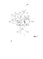
- FIG. 7 Another embodiment will be described with reference to FIG. 7 described. This embodiment is different from the previously described by the fact that it is about moving Gaskets at a landing door wing goes.
- These shaft door rollers 79.1, 79.2 are open when opened the cabin and landing door leaves mechanically with the runners 72.1, 72.1 of a driver unit attached to the cabin door wing sits, interacts.
- the skids 72.1, 72.1 become moved apart (part movement A1) and get into the Contact area of the landing door rollers 79.1, 79.2.
- the landing door roller 79.1 is on a via a rotation axis 73.1 with the Manhole door wing connected shaft door latch 79.3 attached and in relation to the shaft door wing and the one at this immovably fastened shaft door roller 79.2 to the Rotary shaft 73.1 of the shaft door latch 79.3 to the left displaceable. Due to the interaction between the runners 72.1, 72.1 and the shaft door rollers 79.1, 79.2 and is the Shaft door latch 79.3 clockwise about its axis of rotation 73.1 swung and unlocked. After unlocking lead the skids 72.1, 72.1 a common horizontal movement, which is referred to here as opening movement. Through this Opening movement, the car door leaf opens the wing of the Shaft door.
- a coupling mechanism is provided, the driver unit mechanically with the door seals combines.
- the Coupling mechanism a role 73.2, with the shaft door latch 79.3 is rigidly connected with its center on whose axis of rotation is 73.1.
- the movement F1 pulls on the cable 76.
- This pulling movement G1 can, as in connection with the explained in the preceding embodiments, in a Movement of one or more seals are implemented.
- This embodiment may be interpreted as a cable-like Coupling mechanism also a bowdenzugartig designed coupling mechanism or a lever mechanism exhibit.
- a driver unit 35 with integrated Tastkufen 32.4, 32.5 insert (see Fig. 4), in the Device 30, for example, simple runners, as in the Fig. 1 to 3A shown used.
- the cable-like coupling mechanism of Figs. 1 to 3B and FIGS. 6A to 6C can be replaced by another arrangement of individual elements (ropes, rollers, levers and movement execution) be interpreted differently. Instead of a single rope You can also use several rope sections. Instead of A rope can also be another flexible element be used, which is suitable for a force of the Transfer driver unit to the seal.
- the coupling mechanism as a lever system be designed, wherein on the lever system, a tensile force the door seal is exercisable.
- the seals may be designed to have a translational, a rotatory or a combined perform translational and rotational movement.
- the seal carrier can, for example, as a folding element, as Tilting element or as slide, preferably with parallel guidance system, be executed.
- the sealing profile can be optimized according to the application become. For example, materials may be used which are not suitable for sliding seals. Well suited, for example, soft rubber compounds or rubbery foams. It is also possible to the material of the sealing profile to add magnetic particles. bring one then at the sealing surface a metal strip or The like, so arises between the sealing profile and the sealing surface is a magnetic attraction. Thereby the tightness can be further improved.
- a slip clutch for example, on the role 14.1 can be attached or integrated into the roller 14.1.
- the interior of the Lift cabin to be completely sealed.
- Partial movement A1 used to open the seal (s) used may be the same movement for unlocking the car door and / or the shaft door is used.
- a partial movement A1 can also be an actuating movement apply, which is executed to a skid unit with Connecting landing door rollers.
- the device is mechanically with the Door leaf connected and moves when opening and closing the door wing together with this.
- return elements are on the movable door seals provided the seals by themselves in the Sealing position lead back, once no more power over the coupling mechanism is applied to the seals.
- the invention is particularly suitable for high-speed elevators and for lifts that are specially sealed.
Landscapes
- Elevator Door Apparatuses (AREA)
Abstract
Description
- Die Türdichtungen können jeweils kurz vor einer Öffnung der Türflügel von der zugeordneten Dichtfläche wegbewegt werden, um ein Schleifen der Dichtungen vollständig zu verhindern.
- Die Dichtungen lassen sich besser optimieren, da sie - je nach Anwendung - zum Beispiel nur auf Druck beansprucht werden.
- Die Dichtungen können so ausgestaltet und angeordnet werden, dass sie in ein Gegenstück eingreifen, um so eine noch bessere Abdichtung zu erzielen.
- Der Aufzugsschacht kann besser und vor allem länger gegen Rauch und Brandgase abgeschottet werden.
- Der störende Einfluss der Kaminwirkung des Aufzugsschachtes kann durch die Anwendung der erfindungsgemässen Dichtvorrichtung an den Schachttüren reduziert werden.
- Störende Geräusche (Klappergeräusche der Dichtungsmechanik, Schleifgeräusche der Dichtungen) können besser unterdrückt oder sogar verhindert werden.
- Durch das Anheben bzw. Wegbewegen der Dichtungen wird die Reibung beim Öffnen und Schliessen der Türflügel im Vergleich zu Türen mit konventionellen Dichtungen verringert. Man braucht dadurch geringere Kräfte zum Öffnen und Schliessen.
- Fig. 1
- einen Kabinentürflügel, gemäss Erfindung, in einer schematischen Seitenansicht, der eine Mitnehmereinheit, einen ersten seilzugartig ausgelegten Kopplungsmechanismus und zwei bewegbare Dichtungen umfasst;
- Fig. 2
- einen Kabinentürflügel, gemäss Erfindung, in einer schematischen Seitenansicht, der eine Mitnehmereinheit, einen zweiten seilzugartig ausgelegten Kopplungsmechanismus und drei bewegbare Dichtungen umfasst;
- Fig. 3A
- einen dritten Kopplungsmechanismus mit einer bewegbaren Dichtung, gemäss Erfindung, in einer schematischen Ansicht, wobei sich die Dichtung in einer Dichtposition befindet;
- Fig. 3B
- den dritten Kopplungsmechanismus in einer schematischen Ansicht, wobei sich die Dichtung in einer Öffnungsposition befindet;
- Fig. 4
- einen vierten Kopplungsmechanismus mit einer bewegbaren Dichtung, gemäss Erfindung;
- Fig. 5
- einen Kabinentürflügel, gemäss Erfindung, in einer schematischen Seitenansicht, der eine Mitnehmereinheit, einen fünften bowdenzugartig ausgelegten Kopplungsmechanismus und drei bewegbare Dichtungen umfasst;
- Fig. 6A
- eine Schnittdarstellung eines sechsten Kopplungsmechanismus mit zwei bewegbaren Dichtungen, gemäss Erfindung, in einer schematischen Ansicht, wobei sich die Dichtungen in einer Dichtposition befindet;
- Fig. 6B
- einen Ausschnitt des sechsten Kopplungsmechanismus in einer schematischen Ansicht;
- Fig. 6C
- einen Ausschnitt der unteren Dichtung der Ausführungsform nach Fig. 6A in einer schematischen Ansicht, wobei sich die Dichtung in einer Dichtposition befindet;
- Fig. 6D
- einen Ausschnitt der unteren Dichtung der Ausführungsform nach Fig. 6A in einer schematischen Ansicht, wobei sich die Dichtung in einer Öffnungsposition befindet;
- Fig. 7
- einen siebten Kopplungsmechanismus, gemäss Erfindung, in einer schematischen Ansicht, wobei sich dieser Kopplungsmechanismus an einem Schachttürflügel befindet und dazu ausgelegt ist die Dichtung des Schachttürflügels zu bewegen.
Fig. 3B zeigt einen Ausschnitt der Fig. 3A. Das Seil 16 zieht mit einer Kraft B1 an der Dichtung 17.1 und bringt sie dadurch in eine Öffnungsposition. Die Kraft B1 ist mindestens doppelt so gross wie die Kraft F. Wenn sich die Dichtung 17.1 in der Öffnungsposition befindet, sind die Federn 19 gestaucht und es besteht ein geringer Abstand (Luftspalt) zwischen der Dichtfläche 21 und der Dichtung 17.1.
Claims (14)
- Vorrichtung mit bewegbarer Türdichtung (17.1, 17.2, 17.3; 37; 47 .1, 47.2, 47.3; 57) und einem verschiebbaren Türflügel (11; 41; 51), der Teil einer Aufzugsanlage mit einer Aufzugskabine (66), einer Kabinentüre und Schachttüren ist, wobei die bewegbare Türdichtung (17.1, 17.2, 17.3; 37; 47.1, 47.2, 47.3; 57) so angeordnet ist, dass der Türflügel (11; 41; 51) in geschlossenem Zustand mindestens in einem Bereich durch die Türdichtung (17.1, 17.2, 17.3; 37; 47.1, 47.2, 47.3; 57) in Bezug auf eine Dichtfläche (21; 61) abgedichtet ist, dadurch gekennzeichnet, dass die Vorrichtung folgendes umfasst:eine Mitnehmereinheit (12; 35; 42; 62; 72.1, 72.2), die mit einem Kabinentürflügel (11; 41; 51) verbunden ist und beim Anhalten der Aufzugskabine (66) auf der Höhe eines Stockwerks und vor dem Öffnen des Türflügel (11; 41; 51) eine Teilbewegung (A1) ausführt, undeinen Kopplungsmechanismus (14.1 - 14.5, 15, 16; 32.4, 32.5, 33.1, 33.2, 36, 38; 46; 56, 54.3 - 54.6; 73.1, 73.2, 76), der die Mitnehmereinheit (12; 35; 42; 62; 72.1, 72.2) mechanisch mit der Türdichtung (17.1, 17.2, 17.3; 37; 47.1, 47.2, 47.3; 57) verbindet, um die Türdichtung (17.1, 17.2, 17.3; 37; 47.1, 47.2, 47.3; 57) aus einer Dichtposition in eine Öffnungsposition zu bringen, wenn die Mitnehmereinheit (12; 35; 42; 62; 72.1, 72.2) die Teilbewegung (A1) ausführt.
- Vorrichtung nach Anspruch 1, dadurch gekennzeichnet, dass der Kopplungsmechanismus (14.1 - 14.5, 15, 16; 32.4, 32.5, 33.1, 33.2, 36, 38; 46; 56, 54.3 - 54.6; 73.1, 73.2, 76) so ausgelegt ist, dass er die Teilbewegung (A1) der Mitnehmereinheit (12; 35; 42; 62; 72.1, 72.2) in eine Verschiebungsbewegung (C1, C2, C3) und/oder Rotationsbewegung der Türdichtung (17.1, 17.2, 17.3; 37; 47 .1, 47.2, 47.3; 57) umsetzt.
- Vorrichtung nach Anspruch 1 oder 2, dadurch gekennzeichnet, dass die Türdichtung (17.1, 17.2, 17.3; 37; 47.1, 47.2, 47.3; 57) die Dichtposition einnimmt wenn der Türflügel (11; 41; 51) geschlossen ist, wobei die Türdichtung (17.1, 17.2, 17.3; 37; 47.1, 47.2, 47.3; 57) in dieser Dichtposition den Türflügel (11; 41; 51) gegenüber der Dichtfläche (21; 61) abdichtet, die sich an der Aufzugskabine (66) bzw. am Schachttürrahmen befindet.
- Vorrichtung nach Anspruch 1 oder 2, dadurch gekennzeichnet, dass mehrere bewegbare Türdichtung (17.1, 17.2, 17.3; 37; 47.1, 47.2, 47.3; 57) vorhanden sind, die alle über den Kopplungsmechanismus (14.1 - 14.5, 15, 16; 32.4, 32.5, 33.1, 33.2, 36, 38; 46; 56, 54.3 - 54.6) aus Dichtpositionen in Öffnungspositionen bringbar sind, um einen Innenraum der Aufzugskabine abzudichten.
- Vorrichtung nach Anspruch 1, 2, 3 oder 4, dadurch gekennzeichnet, dass die Vorrichtung mechanisch mit dem Türflügel (11; 41; 51) verbunden ist und sich beim Öffnen und Schliessen des Türflügel (11; 41; 51) solidarisch mit diesem bewegt.
- Vorrichtung nach Anspruch 1, 2, 3, 4 oder 5, dadurch gekennzeichnet, dass der Türflügel (11; 41; 51) so geöffnet werden kann, dass die Türdichtung (17.1, 17.2, 17.3; 37; 47.1, 47.2, 47.3; 57) berührungsfrei längs der Dichtfläche (21; 61) bewegbar ist, wenn sich die Türdichtung (17.1, 17.2, 17.3; 37; 47 .1, 47.2, 47.3; 57) in der Öffnungsposition befindet.
- Vorrichtung nach einem der vorhergehenden Ansprüche, dadurch gekennzeichnet, dass die Türdichtung (17.1, 17.2, 17.3; 37; 47.1, 47.2, 47.3; 57) und der Kopplungsmechanismus (14.1 - 14.5, 15, 16; 32.4, 32.5, 33.1, 33.2, 36, 38; 46; 56, 54.3 - 54.6; 73.1, 73.2, 76) so ausgelegt sind, dass die Türdichtung (17.1, 17.2, 17.3; 37; 47.1, 47.2, 47.3; 57) von selbst, zum Beispiel per Federkraft (F), in die Dichtposition bringbar ist, sobald der Türflügel (11; 41; 51) geschlossen ist.
- Vorrichtung nach einem der vorhergehenden Ansprüche, dadurch gekennzeichnet, dass der Kopplungsmechanismus (14.1 - 14.5, 15, 16; 56; 54.3 - 54.6; 73.1, 73.2, 76) seilzugartig ausgelegt ist und vorzugsweise mindestens eine Umlenkrolle (14.1 - 14.5; 54.3) und ein Seil (16; 56; 76) umfasst, wobei über den Kopplungsmechanismus (14.1 - 14.5, 15, 16; 56; 54.3 - 54.6; 73.1, 73.2, 76) eine Zugkraft auf die Türdichtung (17.1, 17.2, 17.3; 47.1, 47.2, 47.3; 57) ausübbar ist.
- Vorrichtung nach einem der Ansprüche 1 bis 7, dadurch gekennzeichnet, dass der Kopplungsmechanismus (46) als Bowdenzug (36; 46) ausgelegt ist, wobei über den Bowdenzug (36; 46) eine Zugkraft auf die Türdichtung (37) ausübbar ist.
- Vorrichtung nach einem der Ansprüche 1 bis 7, dadurch gekennzeichnet, dass der Kopplungsmechanismus als Hebelsystem ausgelegt ist, wobei über das Hebelsystem eine Zugkraft auf die Türdichtung ausübbar ist.
- Vorrichtung nach einem der vorhergehenden Ansprüche, dadurch gekennzeichnet, dass die Türdichtung (37; 57) einen Dichtungsträger (37.2; 57.2) mit einem Dichtprofil (37.1; 57.1) umfasst, und dass durch den Dichtungsträger (37.2; 57.2) eine translatorische (C1) und/oder rotatorische Bewegung ausführbar ist, um das Dichtprofil (37.1; 57.1) in die Dichtposition zu bringen.
- Aufzugsanlage mit einer Vorrichtung gemäss einem der Ansprüche 1 bis 11.
- Aufzugsanlage nach Anspruch 12, dadurch gekennzeichnet, dass die bewegbare Türdichtung zum Dichten eines Kabinentürflügels (11; 41; 51) dient.
- Aufzugsanlage nach Anspruch 12, dadurch gekennzeichnet, dass die bewegbare Türdichtung zum Dichten eines Schachttürflügels dient.
Priority Applications (1)
| Application Number | Priority Date | Filing Date | Title |
|---|---|---|---|
| EP20040008390 EP1471029B1 (de) | 2003-04-25 | 2004-04-07 | Vorrichtung mit bewegbarer Türdichtung für einen verschiebbaren Türflügel einer Aufzugsanlage und Aufzugsanlage mit einer solchen Vorrichtung |
Applications Claiming Priority (3)
| Application Number | Priority Date | Filing Date | Title |
|---|---|---|---|
| EP03405293 | 2003-04-25 | ||
| EP03405293 | 2003-04-25 | ||
| EP20040008390 EP1471029B1 (de) | 2003-04-25 | 2004-04-07 | Vorrichtung mit bewegbarer Türdichtung für einen verschiebbaren Türflügel einer Aufzugsanlage und Aufzugsanlage mit einer solchen Vorrichtung |
Publications (2)
| Publication Number | Publication Date |
|---|---|
| EP1471029A1 true EP1471029A1 (de) | 2004-10-27 |
| EP1471029B1 EP1471029B1 (de) | 2010-08-11 |
Family
ID=32963800
Family Applications (1)
| Application Number | Title | Priority Date | Filing Date |
|---|---|---|---|
| EP20040008390 Expired - Lifetime EP1471029B1 (de) | 2003-04-25 | 2004-04-07 | Vorrichtung mit bewegbarer Türdichtung für einen verschiebbaren Türflügel einer Aufzugsanlage und Aufzugsanlage mit einer solchen Vorrichtung |
Country Status (1)
| Country | Link |
|---|---|
| EP (1) | EP1471029B1 (de) |
Cited By (2)
| Publication number | Priority date | Publication date | Assignee | Title |
|---|---|---|---|---|
| CN107676017A (zh) * | 2017-11-09 | 2018-02-09 | 胡亚奇 | 一种门 |
| CN116553341A (zh) * | 2023-05-25 | 2023-08-08 | 通用电梯股份有限公司 | 一种层门机械防火装置 |
Citations (1)
| Publication number | Priority date | Publication date | Assignee | Title |
|---|---|---|---|---|
| US4735293A (en) * | 1986-12-01 | 1988-04-05 | Westinghouse Electric Corp. | Hatchway door for elevator system |
-
2004
- 2004-04-07 EP EP20040008390 patent/EP1471029B1/de not_active Expired - Lifetime
Patent Citations (1)
| Publication number | Priority date | Publication date | Assignee | Title |
|---|---|---|---|---|
| US4735293A (en) * | 1986-12-01 | 1988-04-05 | Westinghouse Electric Corp. | Hatchway door for elevator system |
Cited By (2)
| Publication number | Priority date | Publication date | Assignee | Title |
|---|---|---|---|---|
| CN107676017A (zh) * | 2017-11-09 | 2018-02-09 | 胡亚奇 | 一种门 |
| CN116553341A (zh) * | 2023-05-25 | 2023-08-08 | 通用电梯股份有限公司 | 一种层门机械防火装置 |
Also Published As
| Publication number | Publication date |
|---|---|
| EP1471029B1 (de) | 2010-08-11 |
Similar Documents
| Publication | Publication Date | Title |
|---|---|---|
| DE69304628T2 (de) | Verbesserte Einsteigevorrichtung für ein Schienenfahrzeug | |
| EP0513509B1 (de) | Aufzug | |
| AT519949B1 (de) | Spaltüberbrückung für ein Schienenfahrzeug | |
| DE602004011470T2 (de) | Dichtungsvorrichtung für aufzüge | |
| CH702569B1 (de) | Liftschachttür-Entriegelung. | |
| DE2337875C2 (de) | Aufhängevorrichtung für im wesentlichen waagerecht verschiebbare Flügel, wie Türen, Fenster oder dergleichen | |
| DE202009014785U1 (de) | Schiebetür | |
| EP1681420A1 (de) | Fluegelanordnung mit Fahrfluegel und Festfluegel | |
| EP3507161A1 (de) | Vorrichtung zum abdichten zumindest eines türflügels für ein schienenfahrzeug und schienenfahrzeug | |
| EP1514831B1 (de) | Dichtungsvorrichtung für Auzüge mit elekromagnetisch zurückziehbarer Türflügeldichtung | |
| WO2005003502A2 (de) | Sektionaltor | |
| EP1471029B1 (de) | Vorrichtung mit bewegbarer Türdichtung für einen verschiebbaren Türflügel einer Aufzugsanlage und Aufzugsanlage mit einer solchen Vorrichtung | |
| DE2419995C3 (de) | Verriegelungsvorrichtung für eine Stockwerkstür eines Fahrstuhlschachtes | |
| EP1662204B1 (de) | Kamin- oder Ofentür | |
| WO2024002686A1 (de) | Aufzug | |
| EP1034999B1 (de) | Güterwaggon mit einer Schiebewand | |
| EP4288318A1 (de) | Einstiegssystem mit schiebetritt und aktiver dichtung | |
| EP3282078B1 (de) | Horizontal öffnendes rolltor | |
| DE3151778C2 (de) | Fahrzeugschiebedach | |
| DE2108151A1 (de) | Fuehrungsvorrichtung fuer zugmittel | |
| DE19957321B4 (de) | Betätigungsvorrichtung zum gemeinsamen Öffnen und Schließen einer Aufzugkabinentür und einer gegenüberstehenden Aufzugschachttür | |
| DE10202528A1 (de) | Mechanische Verriegelung für eine Fahrkorbschiebetür | |
| EP3421704B1 (de) | Schiebetür mit führungskulisse | |
| DE10347283B4 (de) | Vorrichtung für insbesondere motorisch betätigte Türen eines Schacht- oder Aufzugskabinenzugangs | |
| EP2072449A1 (de) | Türantriebsvorrichtung für Aufzugsanlagen |
Legal Events
| Date | Code | Title | Description |
|---|---|---|---|
| PUAI | Public reference made under article 153(3) epc to a published international application that has entered the european phase |
Free format text: ORIGINAL CODE: 0009012 |
|
| AK | Designated contracting states |
Kind code of ref document: A1 Designated state(s): AT BE BG CH CY CZ DE DK EE ES FI FR GB GR HU IE IT LI LU MC NL PL PT RO SE SI SK TR |
|
| AX | Request for extension of the european patent |
Extension state: AL HR LT LV MK |
|
| 17P | Request for examination filed |
Effective date: 20050413 |
|
| REG | Reference to a national code |
Ref country code: HK Ref legal event code: DE Ref document number: 1070635 Country of ref document: HK |
|
| AKX | Designation fees paid |
Designated state(s): DE FR GB |
|
| GRAP | Despatch of communication of intention to grant a patent |
Free format text: ORIGINAL CODE: EPIDOSNIGR1 |
|
| GRAS | Grant fee paid |
Free format text: ORIGINAL CODE: EPIDOSNIGR3 |
|
| GRAA | (expected) grant |
Free format text: ORIGINAL CODE: 0009210 |
|
| AK | Designated contracting states |
Kind code of ref document: B1 Designated state(s): DE FR GB |
|
| REG | Reference to a national code |
Ref country code: GB Ref legal event code: FG4D Free format text: NOT ENGLISH |
|
| REF | Corresponds to: |
Ref document number: 502004011500 Country of ref document: DE Date of ref document: 20100923 Kind code of ref document: P |
|
| REG | Reference to a national code |
Ref country code: HK Ref legal event code: GR Ref document number: 1070635 Country of ref document: HK |
|
| PLBE | No opposition filed within time limit |
Free format text: ORIGINAL CODE: 0009261 |
|
| STAA | Information on the status of an ep patent application or granted ep patent |
Free format text: STATUS: NO OPPOSITION FILED WITHIN TIME LIMIT |
|
| 26N | No opposition filed |
Effective date: 20110512 |
|
| REG | Reference to a national code |
Ref country code: DE Ref legal event code: R097 Ref document number: 502004011500 Country of ref document: DE Effective date: 20110512 |
|
| REG | Reference to a national code |
Ref country code: FR Ref legal event code: PLFP Year of fee payment: 13 |
|
| REG | Reference to a national code |
Ref country code: FR Ref legal event code: PLFP Year of fee payment: 14 |
|
| REG | Reference to a national code |
Ref country code: FR Ref legal event code: PLFP Year of fee payment: 15 |
|
| PGFP | Annual fee paid to national office [announced via postgrant information from national office to epo] |
Ref country code: GB Payment date: 20220419 Year of fee payment: 19 Ref country code: FR Payment date: 20220427 Year of fee payment: 19 Ref country code: DE Payment date: 20220428 Year of fee payment: 19 |
|
| REG | Reference to a national code |
Ref country code: DE Ref legal event code: R084 Ref document number: 502004011500 Country of ref document: DE |
|
| REG | Reference to a national code |
Ref country code: DE Ref legal event code: R119 Ref document number: 502004011500 Country of ref document: DE |
|
| GBPC | Gb: european patent ceased through non-payment of renewal fee |
Effective date: 20230407 |
|
| PG25 | Lapsed in a contracting state [announced via postgrant information from national office to epo] |
Ref country code: GB Free format text: LAPSE BECAUSE OF NON-PAYMENT OF DUE FEES Effective date: 20230407 |
|
| PG25 | Lapsed in a contracting state [announced via postgrant information from national office to epo] |
Ref country code: GB Free format text: LAPSE BECAUSE OF NON-PAYMENT OF DUE FEES Effective date: 20230407 Ref country code: FR Free format text: LAPSE BECAUSE OF NON-PAYMENT OF DUE FEES Effective date: 20230430 Ref country code: DE Free format text: LAPSE BECAUSE OF NON-PAYMENT OF DUE FEES Effective date: 20231103 |