EP1469282A2 - Dipositif pour produire et projeter des marques lumineuses - Google Patents
Dipositif pour produire et projeter des marques lumineuses Download PDFInfo
- Publication number
- EP1469282A2 EP1469282A2 EP04101568A EP04101568A EP1469282A2 EP 1469282 A2 EP1469282 A2 EP 1469282A2 EP 04101568 A EP04101568 A EP 04101568A EP 04101568 A EP04101568 A EP 04101568A EP 1469282 A2 EP1469282 A2 EP 1469282A2
- Authority
- EP
- European Patent Office
- Prior art keywords
- cylindrical lens
- light beam
- secondary light
- radius
- mark
- Prior art date
- Legal status (The legal status is an assumption and is not a legal conclusion. Google has not performed a legal analysis and makes no representation as to the accuracy of the status listed.)
- Granted
Links
- 230000003993 interaction Effects 0.000 claims abstract description 5
- 230000003287 optical effect Effects 0.000 claims description 37
- 239000003550 marker Substances 0.000 claims description 6
- 230000001427 coherent effect Effects 0.000 claims description 4
- 230000002093 peripheral effect Effects 0.000 claims description 3
- 238000007493 shaping process Methods 0.000 claims description 2
- 230000005484 gravity Effects 0.000 description 4
- 238000010276 construction Methods 0.000 description 3
- 230000000712 assembly Effects 0.000 description 2
- 238000000429 assembly Methods 0.000 description 2
- 230000015572 biosynthetic process Effects 0.000 description 2
- 238000003384 imaging method Methods 0.000 description 2
- 238000012423 maintenance Methods 0.000 description 2
- 238000004519 manufacturing process Methods 0.000 description 2
- 230000005855 radiation Effects 0.000 description 2
- 238000013459 approach Methods 0.000 description 1
- 238000006243 chemical reaction Methods 0.000 description 1
- 230000001419 dependent effect Effects 0.000 description 1
- 238000011161 development Methods 0.000 description 1
- 230000018109 developmental process Effects 0.000 description 1
- 238000005265 energy consumption Methods 0.000 description 1
- 238000013507 mapping Methods 0.000 description 1
- 239000000463 material Substances 0.000 description 1
- 229910000679 solder Inorganic materials 0.000 description 1
Images


Classifications
-
- G—PHYSICS
- G01—MEASURING; TESTING
- G01C—MEASURING DISTANCES, LEVELS OR BEARINGS; SURVEYING; NAVIGATION; GYROSCOPIC INSTRUMENTS; PHOTOGRAMMETRY OR VIDEOGRAMMETRY
- G01C15/00—Surveying instruments or accessories not provided for in groups G01C1/00 - G01C13/00
-
- G—PHYSICS
- G01—MEASURING; TESTING
- G01C—MEASURING DISTANCES, LEVELS OR BEARINGS; SURVEYING; NAVIGATION; GYROSCOPIC INSTRUMENTS; PHOTOGRAMMETRY OR VIDEOGRAMMETRY
- G01C15/00—Surveying instruments or accessories not provided for in groups G01C1/00 - G01C13/00
- G01C15/002—Active optical surveying means
- G01C15/004—Reference lines, planes or sectors
Definitions
- the invention relates to a device for generating and projecting light marks according to the preamble of claim 1.
- Known devices for generating and projecting light marks have to a light source device, a collimating optics and a projection optics on.
- the light source device is used for generating and emitting a primary light beam.
- the collimation optics is to receive the primary Light beam and collimation, parallelization and thereby Expansion into a secondary beam of light and directional emission formed and provided the secondary light beam.
- the Projection optics serve to receive at least part of the secondary light beam and the conversion of the secondary light beam in at least a suitable for at least one light mark tertiary light beam or marking beams and their output and thereby to the projection at least one light mark.
- the invention has for its object to provide a device for generating and Projecting of light marks of the type mentioned in such a way that good and easy in a very simple and yet reliable way visible point marks and line marks with particularly low optical Expenditure and generated as far as possible avoid adjustment operations and are projectable.
- the object is in a device for generating and projecting light marks of the type mentioned according to the invention with the characterizing Characteristics of claim 1 solved.
- Advantageous developments of the invention Apparatus for generating and projecting light marks are subject matter the dependent subclaims.
- the inventive device for projecting light marks is general characterized in that the projection optics with the secondary light beam or part of it is acted upon such that an area the projection optics essentially of a central beam of the secondary Light beam essentially completely effetstrahlbar in such a way is and that at least one edge beam of the secondary light beam adjacent to the central beam of the secondary light beam directly on the edge or mantle of the projection optics passing out such a way is that the central beam of the secondary light beam dispersible by interaction with the projection optics and as part of the tertiary light beam or as a line marker beam for a Light mark is essentially projected in the form of a line and that the at least one marginal ray bundle of the secondary light beam as Part of the tertiary light beam or as a spot mark beam for a light mark can be projected substantially in the form of a dot or spot is.
- a preferred embodiment of the device according to the invention for projecting of light marks is characterized in that the projection optics having a cylindrical lens. Furthermore, the cylindrical lens is with the secondary Light beam or the part thereof acted upon such that a cylinder portion area the cylindrical lens as the area of the projection optics in Essentially from a central beam of the secondary light beam for the light mark substantially in the form of a line substantially is completely Maschinenstrahlbar and that at least one edge of the beam secondary light beam for the light mark substantially in shape a spot or spot adjacent to the central beam of the secondary Light beam directly on the edge or mantle of the cylinder portion as a border or coat of the area of the projection optics broadcastable by is.
- One aspect of the invention is thus a cylindrical lens provided in the projection optics with a light beam, which consists of a primary beam of light through collimation, parallelization and expansion as secondary Light beam results in such irradiation and apply to this, that a part of the secondary light beam, namely a central beam a part of the cylindrical lens, namely a cylinder portion area thereof or a cylinder segment thereof, substantially complete radiates through and that another part of the secondary light beam, namely at least one edge beam directly on the edge or mantle the cylinder lens, namely the cylinder portion area, which is substantially is completely irradiated, passed by or can be sent out.
- the Central beam is irradiated by interaction or refraction with the Cylinder section area scattered or dispersed, so that after Passage through the cylinder portion area or through the cylinder segment in use or in operation on a remote projection screen one Light mark in the form of a line or a line mark results.
- the marginal beams or the edge beam or run on the outside of the jacket the cylindrical lens in the region of the cylinder section over and thus forms in Operation and in the application on a projection surface then provided a corresponding point mark, ie a light mark in the form of a dot or Spot.
- the point mark and the Line mark are placed in a particular spatial relation to each other, so that z. B. on the line mark by the point mark a certain spatial Define reference point and display.
- Particularly advantageous projection and imaging conditions arise when the light source device according to a preferred embodiment the device according to the invention for generating and emitting substantially coherent and / or monochromatic light for the primary Light beam is designed. Then that's when you get really sharp Imaging conditions in operation.
- the light source device has a laser light source or is formed by such. This can be monochromatic coherent Create light with a high intensity
- any laser light source can be used, with particular advantage the use of a laser diode or an array of a plurality Laser diode as a light source device or in the range thereof. These are particularly compact and have a relatively low energy consumption.
- the beam shape of the secondary light beam which interacts with the projection optics.
- Apparatus for beam shaping with respect to the secondary light beam between the collimating optics and the projection optics an aperture device intended.
- This diaphragm device gives the secondary light beam a certain symmetrical shape and spatial extent.
- the aperture device can also be part of the collimation optics.
- the aperture device can be used as a circular shutter or in certain applications be designed as a diaphragm in the form of an ellipse. But also conceivable are rectangular panels. These shapes can form the aperture device itself or it can be used as components of a diaphragm device with a plurality of diaphragms and optionally other components.
- the respective aperture device for. B. as a circular aperture or a rectangular aperture, in relation to the cross section of the limiting secondary beam of light concentric and is arranged.
- the respective aperture device has a geometric Has center or center of gravity and that this geometric center or center of gravity with the geometric center or center of gravity of the cross section of the secondary light beam is approximately coincident.
- the cylindrical lens for the projection optics are basically all Cylinder shapes. However, it is particularly advantageous because of its simplicity the basic shape of a circular cylinder. Accordingly, in a particularly preferred Embodiment of the device according to the invention, the cylindrical lens in Formed a circular cylinder and in particular has a corresponding Circle radius R for the underlying circular area and a corresponding circle Symmetry axis X, with respect to the cylindrical lens rotationally symmetric is trained.
- the cylindrical lens has z. B. an optical effective diameter D. This is, especially with respect to the secondary light beam, approximately identical with the double radius R of the underlying circle base area, if the Cylindrical lens is a circular cylinder is used.
- the secondary light beam having a substantially elliptical cross section can be formed. This particular has a certain large Half-axis a and a certain small semi-axis b.
- the large semiaxis a of the cross section of the secondary light beam chosen to be approximately perpendicular to the axis of symmetry X of the cylinder axis extending and trained.
- the large semiaxis a of the cross section of the secondary Light beam in about 8 times the radius R of the cylindrical lens or corresponds to 4 times the optical effective diameter D of the cylindrical lens. additionally or alternatively, it is provided that the small semiaxis b of the cross section of the secondary light beam about 2 times the radius R of the Cylindrical lens or the 1-fold effective diameter of the cylindrical lens corresponds.
- a circular aperture whose radius Rkb is about 4 times the radius R the cylindrical lens or about 2 times the optical effective diameter D of the cylindrical lens equivalent.
- a rectangular shutter may be provided, which has a first edge c perpendicular to the axis of symmetry X of the cylindrical lens, about 3 times the radius R of the cylindrical lens or the 1.5 times optical Effective diameter D of the cylindrical lens corresponds, and which a second Edge d parallel to the axis of symmetry X of the cylindrical lens has, which approximately 5 times the radius of the cylindrical lens or about 2.5 times the effective optical diameter D corresponds to the cylindrical lens.
- the large semiaxis a of the cross section of the secondary light beam extending approximately parallel to the axis of symmetry X of the cylindrical lens chosen and trained.
- the large semi-axis a of the cross section of the secondary light beam is approximately 12 times Radius R of the cylindrical lens or about 6 times the optical effective diameter D the cylindrical lens corresponds.
- the small semiaxis b of the cross section of the secondary light beam in about 4 times the radius R of the cylindrical lens or about twice Effective diameter D of the cylindrical lens corresponds.
- this When using the rectangular shutter, this has a first edge c vertically to the axis of symmetry X of the cylindrical lens, which is about 3 times or about the 6-fold radius R of the cylindrical lens or about 1.5 times or about the 3 times the optical effective diameter D of the cylindrical lens corresponds. Furthermore owns the rectangular aperture a second edge d parallel to the axis of symmetry of the X Cylindrical lens, and corresponding to about 4 times the radius R of the cylindrical lens or about 2 times the optical effective diameter D of the cylindrical lens.
- the cylindrical lens is formed in the form of a slant cylinder, wherein at least one inclined relative to the axis of symmetry X of the cylindrical lens Base A or end face A is provided.
- This inclined base A or end surface A is provided formed mirrored.
- the arrangement is chosen so that through the mirrored base A or end face A at least a part of the secondary light beam is so reflective, that outside the plane passing through the device itself and through the tertiary light beam is formed for the light mark, an external and another light mark essentially in the form of a dot or spot can be mapped or projectable.
- both base surfaces A or end surfaces A of the cylindrical lens are inclined, mirrored and formed such that two external and further light marks substantially in the form of a dot or spot can be imaged or projected.
- line marks z As a series of discrete ones Points are generated by means of diffractive elements. The disadvantage here is that the line is not continuous. Another conventional line brand is produced by a simple cylindrical lens. The downside is that the Intensity is distributed on a wide line, making the line at great distance in certain lighting conditions of the environment no longer clearly visible is. There is no reference point on the line, but in many cases is desired. For example, if the line is vertically aligned to one determine leveled point on the line.
- One idea of the invention is the mapping of a reference point to a line mark to allow at a great distance without giving up the continuity of the line without. This is achieved by the device according to the invention.
- the diameter of the collimated or focused at a certain distance Laser beam is greater than the optical effective diameter of the cylindrical lens.
- two edge regions of the collimated laser beam can be unhindered continue to spread forward.
- one line and two points are reversed the center formed. From a certain distance from the cylindrical lens, which depends on the outer diameter of the cylindrical lens, ie in the far field, the two marginal beams of the points will interfere to one point.
- the beam diameter and the aperture can take certain forms and be designed at the edges of the main laser beam so that the formation of the Point in the far field is affected.
- the panels may be in the form of a circle or rectangle.
- the major axis or large semiaxis a of the laser beam can be perpendicular to the cylindrical lens axis Z stand.
- the marginal ray can be cut through a circular aperture, so that the one side of the marginal ray gets a curvature, d. H. the marginal ray takes an asymmetrical shape. In contrast, the marginal ray is a rectangular aperture approximately symmetrical. The diffraction image will be better Have symmetry.
- Influence of the aperture size The larger the aperture diameter or the longer the Width of the rectangle becomes, the narrower the diffraction image appears in horizontal Direction, d. H. it results in a better spatial resolution in horizontal Direction.
- the major axis or semi-major axis a of the ellipse of the cross section of the secondary Light beam of the laser beam can also be parallel to the cylinder axis the cylindrical lens stand.
- These embodiments are also called line-dot lasers designated.
- the aperture shape has more influence on the diffraction pattern as the aperture size, because the width of the laser beam in these cases requires is limited. The attempt to increase the width brings the big disadvantage energy loss, the visibility of the line mark also suffers.
- the major axis a of the ellipse of the laser beam can then be parallel to the connecting line be aligned with two round aperture.
- two partial beams are deflected by 90 °.
- the short side (or the width) b of the cross section of the laser beam must be greater than that Diameter D of the cylindrical lens, so that a part of the laser beam passing both sides of the cylinder lens can continue to spread.
- the two in this way generated beam points are 90 ° perpendicular to the surface, which is the line laser spans.
- the two modules are mounted on a support so that the two line marks the modules A and B are perpendicular to each other, the two dot marks pointing up and down in the lot.
- the point lasers of modules A and B form a rectangular coordinate system and have the same origin (coincidence).
- the whole construction is on a pendulum, for example on a stable one String or thread, hung up. By the action of gravity is the whole Structure aligned in the Lot and can swing back and forth.
- Two possible layers of the line-multibeam laser are conceivable, namely the laser align so that the two beam spots are in the solder, or the laser so align that the two beam points and the point mark in horizontal Location lie.
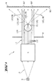
- Fig. 1 is a schematic plan view of an embodiment of the invention Device 1 for generating and projecting light marks.
- Main components of the device 1 are the light source device Q, the Kollimationsoptik K and the projection optics P.
- the light source device Q generates primary light in the form of a primary light beam L1.
- the collimation optics K takes at least part of the primary light beam L1 and forms from this a secondary light beam L2, which in comparison collimated to the primary light beam L1, parallelized and optionally is widened.
- the Kollimationsoptik K is the secondary Light beam L2 emitted or emitted in a directed manner. This is done in such a way that the projection optics P provided in the beam path at least partially irradiated.
- the projection optics P is the embodiment 1 essentially of a cylindrical lens Z. In Fig. 1 is a Cross section through the entire optical arrangement of the device according to the invention 1, so that the cylindrical lens Z of the projection optics P here in Form of a circle appears.
- the cylindrical lens Z is so with the secondary light beam L2 is applied to a cylinder section area ZA of the cylinder lens Z by a central beam L2Z of the secondary light beam L2 in Essentially completely irradiated.
- Edge beam L2R of the secondary light beam L2 am Mantle M of the cylindrical lens Z directly and in a substantially unhindered form past, in the form of an edge beam L3R of the tertiary light beam L3.
- the central beam L2Z of the secondary light beam L2 undergoes refraction interaction with the material of the Cylindrical lens Z of the projection optics P. This is the central beam L2Z scattered, widened or spread, so that the individual rays of the the cylinder lens Z leaving central beam L3Z substantially in a well-defined plane scattered across the room to measure.
- two marginal rays L2R and L3R, respectively, of the secondary light beam L2 and the tertiary light beam L3 are provided.
- These edge beams L2R, L3R lead in the application to the formation of dot marks MP, when an object, for. B. in the form of a wall W, is hit by the tertiary light beam L3.
- the so-called near field is shown, in which the two boundary beams L2R, L3R still lead to separated point marks MP.
- the corresponding line mark ML is also shown on the wall W, which is generated by the corresponding central beam L3Z of the tertiary light beam L3.
- the peripheral rays L3R of the tertiary light beam L3 thus form Beam LMP for point marks, while the central beam L3Z of the tertiary light beam L3, a beam LML for the line mark forms.
- a diaphragm device B To influence the geometry of the secondary light beam L2 and the corresponding edge beams L2R and central beams L2Z is in the embodiment 1 between the collimation optics K and the projection optics P a diaphragm device B is provided.
- FIG. 2 shows a structure similar to the construction of FIG. 1 for a device according to the invention Device 1 for generating and emitting light marks.
- the light source device Q consists of a laser diode or of a Laser diode array.
- the collimation optics is thereby more concrete, that here indicated the various optical input and output lens systems are.
- a diaphragm as in the embodiment of Fig. 1 is shown in the Kollimationsoptik K integrated designed provided.
- FIG. 3A shows in the form of a photograph the light marks projected onto the wall W. in the form of the line mark ML and in the form of the two point marks MP, like them already schematically indicated in Fig. 1.
- Fig. 3A shows the conditions of the radiation field in the near field, ie the so-called near field the intensity distribution.
- Fig. 3B illustrates the intensity distribution in the form of a photograph in the so-called far field, so comparatively far from the device 1 for generating and projecting light marks.
- FIGS. 4A to 5B illustrate various geometric relationships between the secondary light beam L2 of the diaphragm B or B used Aperture device B and the cylindrical lens Z of the projection optics P.
- the cylindrical lens Z of the Projection optics P is based on a circular cylinder, which as a base a Circle having the radius R has. Accordingly, in the following figures the cylindrical lens Z an effective or optical effective diameter D, which 2 times the radius R corresponds. All other information is therefore relative information Compared to the radius R of the cylindrical lens Z underlying circle base.
- the secondary light beam L2 has an elliptical cross section with a large semiaxis a and a small semi-axis b.
- the large semiaxis a is perpendicular to Symmetry axis X of the cylindrical lens Z oriented and corresponds approximately to 8 times Radius of the cylindrical lens Z or the simple optical effective diameter D of the cylindrical lens Z.
- the small semiaxis b of the secondary light beam L2 is aligned parallel to the axis of symmetry X of the cylindrical lens Z and corresponds in extent to twice the radius R of the cylindrical lens Z or the optical effective diameter D of the cylindrical lens Z.
- Fig. 4A is a circular aperture B with a diaphragm diameter Rkb used, which is twice the optical effective diameter D of the cylindrical lens Z, ie 4 times the radius of the cylindrical lens Z corresponds.
- the aperture B and the Secondary light beams L2 are arranged concentrically with each other. shown are also the marginal rays L2R of the secondary light beam L2, which run past the jacket M of the cylindrical lens Z. It is also recognizable Central beam L2Z of the secondary light beam L2, which the Cylinder section range ZA of the cylindrical lens Z of the projection optics P substantially completely irradiated.
- a rectangular diaphragm B is used in FIG. 4B.
- the cross section of the secondary light beam L2 formed concentric with the rectangular aperture.
- the major semi-axis a is the cross-section of the secondary light beam L2 aligned in parallel to the axis of symmetry X of the cylindrical lens Z and has an extension which is 12 times Radius R of the cylindrical lens Z or 6 times the optical effective diameter D corresponds to the cylindrical lens Z.
- the small semiaxis b of the cross section of the secondary light beam L2 is in each case perpendicular to the axis of symmetry X.
- the cylindrical lens Z is formed and has an extension which is 4 times Radius R of the cylindrical lens Z or the double optical effective diameter D corresponds to the cylindrical lens Z.
- a rectangular aperture B is provided, and although with a long edge c parallel or perpendicular to the axis of symmetry X the Cylindrical lens Z.
- the long edge c has an extension 4 times the radius R of the cylindrical lens (2 times the optical effective diameter D) or 6 times Radius of the cylindrical lens Z (3 times the optical effective diameter D) corresponds.
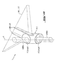
- FIGS. 7 to 10 show embodiments of the device 1 according to the invention for generating and projecting light marks, in which the cylindrical lens Z the projection optics P is based on a skew cylinder, with opposite the axis of symmetry X of the cylindrical lens Z by 45 ° inclined end surfaces A, which Moreover, such are mirrored and arranged that a part of the secondary Light beam L2 can be reflected on it so that perpendicular to the projection level for the line mark ML external and further point marks (MPe) can be projected and mapped.
- These additional and external Dot marks or spot marks MPe become over at the mirroring end faces A of the cylindrical lens Z reflected light beams LMMe mediates, as the in Fig. 7 is shown schematically.
- FIG. 8 shows a further schematic and sectional side view of FIG. 7 illustrated situation, which also provides further dimensioning information are.
- the diameter of the cylindrical lens Z is again denoted by R.
- the line mark for generating to project here has a height which dern 1.8 times the radius R of Cylindrical lens Z corresponds.
- Fig. 9 shows details with respect to the secondary light beam L2 and the Aperture B, as in a particular embodiment of the in Figs. 7 and 8 shown device 1 for generating and projecting light marks used could become.
- the large semiaxis a which is shown in FIG. 9 not shown, aligned parallel to the axis of symmetry X of the cylindrical lens Z. and has an extension which is 9 times the radius R of the cylindrical lens Z or 4.5 times the effective optical diameter D of the cylindrical lens Z equivalent.
- the small semiaxis b of the cross section of the secondary light beam L2 is extended perpendicular to the axis of symmetry X of the cylindrical lens Z. and has an extension of about 3 times the radius R of the cylindrical lens Z. or 1.5 times the effective optical diameter D of the cylindrical lens Z.
- the diaphragm B consists of a circular plate with three recesses B1, B2 and B3.
- the first recess B1 has Recheckform for generating the marginal rays L2R and the central beam L2Z to generate the actual Line mark ML and the actual point mark MP.
- Fig. 10 shows a perspective view from above of the conditions as they are can result in the application of the arrangement shown in FIGS. 7 to 9.
- the incident secondary light beam is L2 not shown.
- upper and lower end surfaces A are formed as mirrors.
- At these reflective end surfaces of the cylindrical lens Z are shares of here not shown secondary light beam L2 perpendicular to the top or down reflected, in the form of beams LMMe for trainee external point markers MPe.
- the phrase "vertical" refers to that plane, that of the tertiary beam L3Z or the line mark beam LML is formed. Shown are also the Dot marker bundle LMP, which again in the form of marginal rays L3Z of the tertiary beam L3 appear in appearance.
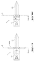
- FIGS. 11A and 11B show devices 1 according to the invention once again are formed in the form of modules A and B, in side cross-sectional views.
- the module A corresponds approximately to an embodiment, as they is shown in Figs. 7 to 10.
- module B essentially has the structure as shown in Figs. 1 to 6B.
- Fig. 12 shows an arrangement of the modules A and B in the region of a positioning device 10.
- This positioning device 10 is formed by a Modulnlie G, z. B. in the form of a housing, in or on which the modules A and B, and optionally also other modules are attached and arranged.
- the order The modules A and B are such that the tertiary light beams L3 each spanned planes are approximately perpendicular to each other and that the straight lines defined by the respective dot mark beams LMP also perpendicular to each other.
- the housing or the module carrier G is attached to a shuttle thread F such that when vertically aligned of the pendulum thread F and the module carrier G formed pendulum, z. B. in the gravitational field of the earth, the shuttle thread F on the defined by the module A. Level is perpendicular and to the plane defined by the module B. runs parallel.
- FIGS. 13 to 14B describe possible positioning and orientations, as in the embodiment according to FIG. 1 to 6B or in the embodiment according to FIGS. 7 to 10 are conceivable.
- Fig. 13 an arrangement according to FIGS. 1 to 6B, three different assume basic positions to each other.
- the embodiment 7 to 10 are only two fundamentally different positions possible in two-dimensional space.
Landscapes
- Physics & Mathematics (AREA)
- Engineering & Computer Science (AREA)
- General Physics & Mathematics (AREA)
- Radar, Positioning & Navigation (AREA)
- Remote Sensing (AREA)
- Length Measuring Devices By Optical Means (AREA)
- Non-Portable Lighting Devices Or Systems Thereof (AREA)
- Optical Elements Other Than Lenses (AREA)
Applications Claiming Priority (2)
| Application Number | Priority Date | Filing Date | Title |
|---|---|---|---|
| DE10317958A DE10317958B4 (de) | 2003-04-17 | 2003-04-17 | Vorrichtung zum Erzeugen und Projizieren von Lichtmarken |
| DE10317958 | 2003-04-17 |
Publications (3)
| Publication Number | Publication Date |
|---|---|
| EP1469282A2 true EP1469282A2 (fr) | 2004-10-20 |
| EP1469282A3 EP1469282A3 (fr) | 2007-10-24 |
| EP1469282B1 EP1469282B1 (fr) | 2010-08-04 |
Family
ID=32892427
Family Applications (1)
| Application Number | Title | Priority Date | Filing Date |
|---|---|---|---|
| EP04101568A Expired - Lifetime EP1469282B1 (fr) | 2003-04-17 | 2004-04-16 | Dipositif pour produire et projeter des marques lumineuses |
Country Status (4)
| Country | Link |
|---|---|
| US (1) | US7136233B2 (fr) |
| EP (1) | EP1469282B1 (fr) |
| JP (1) | JP2004317519A (fr) |
| DE (2) | DE10317958B4 (fr) |
Cited By (4)
| Publication number | Priority date | Publication date | Assignee | Title |
|---|---|---|---|---|
| EP1519147A1 (fr) * | 2003-09-25 | 2005-03-30 | HILTI Aktiengesellschaft | Séparateur de faisceau |
| WO2010108720A1 (fr) * | 2009-03-26 | 2010-09-30 | Robert Bosch Gmbh | Appareil laser à ligne à nivellement automatique |
| WO2010108718A3 (fr) * | 2009-03-26 | 2011-01-06 | Robert Bosch Gmbh | Appareil laser multi-raies à autonivellement |
| EP2469226A3 (fr) * | 2010-12-22 | 2014-01-15 | HILTI Aktiengesellschaft | Système optique pour la formation d'un rayonnement laser ainsi que système laser doté d'un tel système optique |
Families Citing this family (11)
| Publication number | Priority date | Publication date | Assignee | Title |
|---|---|---|---|---|
| DE202006009807U1 (de) * | 2006-06-21 | 2007-08-02 | Horn, Paul | Tragbare Nivelliereinrichtung mit einer Projektionseinheit zur Erzeugung zumindest einer Projektionslinie |
| JP2008139204A (ja) * | 2006-12-04 | 2008-06-19 | Toyo Techno Kk | レーザー墨出し器用レーザーヘッド |
| JP2008171960A (ja) * | 2007-01-10 | 2008-07-24 | Canon Inc | 位置検出装置及び露光装置 |
| TWM349483U (en) * | 2008-05-28 | 2009-01-21 | Muratec Kds Corp | Synchronous display composition for spots and lines of light rays |
| US7992310B2 (en) * | 2008-08-13 | 2011-08-09 | Trimble Navigation Limited | Reference beam generator and method |
| CN101957198B (zh) * | 2010-08-11 | 2012-10-03 | 陆建红 | 适于点、线激光输出切换的激光放样装置 |
| DE102011089837A1 (de) * | 2011-12-23 | 2013-06-27 | Hilti Aktiengesellschaft | Optisches System |
| US9303990B2 (en) | 2014-04-11 | 2016-04-05 | Black & Decker Inc. | Laser line generating device |
| EP3358391A4 (fr) * | 2015-09-30 | 2019-08-14 | Huanic Corporation | Système optique pour faciliter le positionnement d'images |
| EP3425334B1 (fr) | 2017-07-07 | 2022-09-07 | Leica Geosystems AG | Niveau laser |
| JP6987347B2 (ja) * | 2018-03-29 | 2021-12-22 | マクセル株式会社 | プロジェクタ |
Citations (3)
| Publication number | Priority date | Publication date | Assignee | Title |
|---|---|---|---|---|
| DE9307359U1 (fr) * | 1993-05-14 | 1993-07-22 | Lap Gmbh Laser Applikationen, 2120 Lueneburg, De | |
| US5838431A (en) * | 1996-01-16 | 1998-11-17 | Asahi Kogaku Kogyo Kabushiki Kaisha | Laser marking device |
| DE10116563A1 (de) * | 2001-04-04 | 2002-10-10 | Hilti Ag | Mehrachslaserstrahler mit optischem Strahlteiler |
Family Cites Families (3)
| Publication number | Priority date | Publication date | Assignee | Title |
|---|---|---|---|---|
| DE4339710C2 (de) * | 1993-11-22 | 1997-02-13 | Univ Schiller Jena | Optoelektronische Abstandsmeßeinrichtung |
| DE19533586A1 (de) * | 1995-09-01 | 1997-03-06 | Berliner Inst Fuer Optik Gmbh | System zur optischen Markierung von Strahlung |
| CN1293822A (zh) * | 1999-01-06 | 2001-05-02 | 株式会社尼康 | 投影光学系统、投影光学系统的制造方法和使用该光学系统的投影曝光装置 |
-
2003
- 2003-04-17 DE DE10317958A patent/DE10317958B4/de not_active Expired - Fee Related
-
2004
- 2004-04-12 US US10/822,618 patent/US7136233B2/en active Active
- 2004-04-16 EP EP04101568A patent/EP1469282B1/fr not_active Expired - Lifetime
- 2004-04-16 DE DE502004011466T patent/DE502004011466D1/de not_active Expired - Lifetime
- 2004-04-19 JP JP2004123102A patent/JP2004317519A/ja active Pending
Patent Citations (3)
| Publication number | Priority date | Publication date | Assignee | Title |
|---|---|---|---|---|
| DE9307359U1 (fr) * | 1993-05-14 | 1993-07-22 | Lap Gmbh Laser Applikationen, 2120 Lueneburg, De | |
| US5838431A (en) * | 1996-01-16 | 1998-11-17 | Asahi Kogaku Kogyo Kabushiki Kaisha | Laser marking device |
| DE10116563A1 (de) * | 2001-04-04 | 2002-10-10 | Hilti Ag | Mehrachslaserstrahler mit optischem Strahlteiler |
Cited By (7)
| Publication number | Priority date | Publication date | Assignee | Title |
|---|---|---|---|---|
| EP1519147A1 (fr) * | 2003-09-25 | 2005-03-30 | HILTI Aktiengesellschaft | Séparateur de faisceau |
| WO2010108720A1 (fr) * | 2009-03-26 | 2010-09-30 | Robert Bosch Gmbh | Appareil laser à ligne à nivellement automatique |
| WO2010108718A3 (fr) * | 2009-03-26 | 2011-01-06 | Robert Bosch Gmbh | Appareil laser multi-raies à autonivellement |
| CN102362148A (zh) * | 2009-03-26 | 2012-02-22 | 罗伯特·博世有限公司 | 自调平的多线激光器 |
| US8813379B2 (en) | 2009-03-26 | 2014-08-26 | Robert Bosch Gmbh | Self-leveling multi-line laser device |
| US9891051B2 (en) | 2009-03-26 | 2018-02-13 | Robert Bosch Gmbh | Self-leveling multi-line laser device |
| EP2469226A3 (fr) * | 2010-12-22 | 2014-01-15 | HILTI Aktiengesellschaft | Système optique pour la formation d'un rayonnement laser ainsi que système laser doté d'un tel système optique |
Also Published As
| Publication number | Publication date |
|---|---|
| DE502004011466D1 (de) | 2010-09-16 |
| US20040207848A1 (en) | 2004-10-21 |
| EP1469282B1 (fr) | 2010-08-04 |
| DE10317958A1 (de) | 2004-11-18 |
| US7136233B2 (en) | 2006-11-14 |
| EP1469282A3 (fr) | 2007-10-24 |
| JP2004317519A (ja) | 2004-11-11 |
| DE10317958B4 (de) | 2005-09-08 |
Similar Documents
| Publication | Publication Date | Title |
|---|---|---|
| EP3365593B1 (fr) | Module lumineux à microprojection pour projecteur de véhicule | |
| EP2910847B1 (fr) | Module d'éclairage d'un projecteur de véhicule automobile et projecteur avec un tel module d'éclairage | |
| EP1469282B1 (fr) | Dipositif pour produire et projeter des marques lumineuses | |
| DE202018006300U1 (de) | Laserabtastvorrichtung, Laserradarsatz und Abtastverfahren des Laserradarsatzes | |
| DE3212698C2 (fr) | ||
| EP3864341B1 (fr) | Phare à feu de croisement | |
| EP3300192B1 (fr) | Dispositif d'éclairage | |
| EP2414886B1 (fr) | Module d'eclairage avec dispositif de mise en forme d'un faisceau | |
| DE102013217843A1 (de) | Projektionsoptik zum Einsatz in einem LED-Modul eines Kraftfahrzeugscheinwerfers, sowie LED-Modul und Kraftfahrzeugscheinwerfer mit einer solchen Projektionsoptik | |
| DE102009021251A1 (de) | Vorrichtung zur Formung von Laserstrahlung sowie Laservorrichtung mit einer derartigen Vorrichtung | |
| EP1067422A2 (fr) | Séparateur de faisceaux pour diviser un faisceau de lumière en sous-faisceaux | |
| EP3438524A1 (fr) | Luminaire | |
| DE112016003392T5 (de) | Optische Vorrichtung | |
| DE102016211339A1 (de) | Laserlinienprojektor zur Reduktion von Granulation | |
| DE2123844C3 (de) | Kraftfahrzeugscheinwerfer mit asymmetrischem Abblendlicht | |
| DE102012107456A1 (de) | Anordnung zur Formung von Laserstrahlung | |
| DE19941030C1 (de) | Laseranordnung für ein mehrstrahliges Laserrichtgerät | |
| EP2411763B1 (fr) | Marquage laser avec système de coordonnées | |
| DE102007038704B4 (de) | Substratbelichtungsvorrichtung | |
| DE639774C (de) | Blendungsfreier Automobilscheinwerfer | |
| WO2023031012A1 (fr) | Dispositif d'éclairage pour un véhicule à moteur | |
| DE10334048A1 (de) | Laser-Lichtlinien-Strahlenemissionsgerät und Staubschutzabdeckung für dieses Gerät | |
| DE102011085978A1 (de) | Laser-leuchtstoff-vorrichtung mit laserarray | |
| DE102017122956A1 (de) | Leuchte | |
| DE19920293A1 (de) | Anordnung und Vorrichtung zur optischen Strahltransformation |
Legal Events
| Date | Code | Title | Description |
|---|---|---|---|
| PUAI | Public reference made under article 153(3) epc to a published international application that has entered the european phase |
Free format text: ORIGINAL CODE: 0009012 |
|
| AK | Designated contracting states |
Kind code of ref document: A2 Designated state(s): AT BE BG CH CY CZ DE DK EE ES FI FR GB GR HU IE IT LI LU MC NL PL PT RO SE SI SK TR |
|
| AX | Request for extension of the european patent |
Extension state: AL LT LV MK |
|
| PUAL | Search report despatched |
Free format text: ORIGINAL CODE: 0009013 |
|
| AK | Designated contracting states |
Kind code of ref document: A3 Designated state(s): AT BE BG CH CY CZ DE DK EE ES FI FR GB GR HU IE IT LI LU MC NL PL PT RO SE SI SK TR |
|
| AX | Request for extension of the european patent |
Extension state: AL LT LV MK |
|
| 17P | Request for examination filed |
Effective date: 20080424 |
|
| AKX | Designation fees paid |
Designated state(s): CH DE FR GB IT LI |
|
| 17Q | First examination report despatched |
Effective date: 20081223 |
|
| GRAP | Despatch of communication of intention to grant a patent |
Free format text: ORIGINAL CODE: EPIDOSNIGR1 |
|
| GRAS | Grant fee paid |
Free format text: ORIGINAL CODE: EPIDOSNIGR3 |
|
| GRAA | (expected) grant |
Free format text: ORIGINAL CODE: 0009210 |
|
| AK | Designated contracting states |
Kind code of ref document: B1 Designated state(s): CH DE FR GB IT LI |
|
| REG | Reference to a national code |
Ref country code: GB Ref legal event code: FG4D Free format text: NOT ENGLISH |
|
| REG | Reference to a national code |
Ref country code: CH Ref legal event code: EP |
|
| REF | Corresponds to: |
Ref document number: 502004011466 Country of ref document: DE Date of ref document: 20100916 Kind code of ref document: P |
|
| PLBE | No opposition filed within time limit |
Free format text: ORIGINAL CODE: 0009261 |
|
| STAA | Information on the status of an ep patent application or granted ep patent |
Free format text: STATUS: NO OPPOSITION FILED WITHIN TIME LIMIT |
|
| 26N | No opposition filed |
Effective date: 20110506 |
|
| REG | Reference to a national code |
Ref country code: DE Ref legal event code: R097 Ref document number: 502004011466 Country of ref document: DE Effective date: 20110506 |
|
| REG | Reference to a national code |
Ref country code: FR Ref legal event code: PLFP Year of fee payment: 13 |
|
| REG | Reference to a national code |
Ref country code: FR Ref legal event code: PLFP Year of fee payment: 14 |
|
| REG | Reference to a national code |
Ref country code: FR Ref legal event code: PLFP Year of fee payment: 15 |
|
| PGFP | Annual fee paid to national office [announced via postgrant information from national office to epo] |
Ref country code: IT Payment date: 20230426 Year of fee payment: 20 Ref country code: FR Payment date: 20230420 Year of fee payment: 20 Ref country code: DE Payment date: 20230420 Year of fee payment: 20 Ref country code: CH Payment date: 20230502 Year of fee payment: 20 |
|
| PGFP | Annual fee paid to national office [announced via postgrant information from national office to epo] |
Ref country code: GB Payment date: 20230419 Year of fee payment: 20 |
|
| REG | Reference to a national code |
Ref country code: DE Ref legal event code: R071 Ref document number: 502004011466 Country of ref document: DE |