EP1469282A2 - Device for producing and projecting light marks - Google Patents
Device for producing and projecting light marks Download PDFInfo
- Publication number
- EP1469282A2 EP1469282A2 EP04101568A EP04101568A EP1469282A2 EP 1469282 A2 EP1469282 A2 EP 1469282A2 EP 04101568 A EP04101568 A EP 04101568A EP 04101568 A EP04101568 A EP 04101568A EP 1469282 A2 EP1469282 A2 EP 1469282A2
- Authority
- EP
- European Patent Office
- Prior art keywords
- cylindrical lens
- light beam
- secondary light
- radius
- mark
- Prior art date
- Legal status (The legal status is an assumption and is not a legal conclusion. Google has not performed a legal analysis and makes no representation as to the accuracy of the status listed.)
- Granted
Links
Images


Classifications
-
- G—PHYSICS
- G01—MEASURING; TESTING
- G01C—MEASURING DISTANCES, LEVELS OR BEARINGS; SURVEYING; NAVIGATION; GYROSCOPIC INSTRUMENTS; PHOTOGRAMMETRY OR VIDEOGRAMMETRY
- G01C15/00—Surveying instruments or accessories not provided for in groups G01C1/00 - G01C13/00
-
- G—PHYSICS
- G01—MEASURING; TESTING
- G01C—MEASURING DISTANCES, LEVELS OR BEARINGS; SURVEYING; NAVIGATION; GYROSCOPIC INSTRUMENTS; PHOTOGRAMMETRY OR VIDEOGRAMMETRY
- G01C15/00—Surveying instruments or accessories not provided for in groups G01C1/00 - G01C13/00
- G01C15/002—Active optical surveying means
- G01C15/004—Reference lines, planes or sectors
Definitions
- the invention relates to a device for generating and projecting light marks according to the preamble of claim 1.
- Known devices for generating and projecting light marks have to a light source device, a collimating optics and a projection optics on.
- the light source device is used for generating and emitting a primary light beam.
- the collimation optics is to receive the primary Light beam and collimation, parallelization and thereby Expansion into a secondary beam of light and directional emission formed and provided the secondary light beam.
- the Projection optics serve to receive at least part of the secondary light beam and the conversion of the secondary light beam in at least a suitable for at least one light mark tertiary light beam or marking beams and their output and thereby to the projection at least one light mark.
- the invention has for its object to provide a device for generating and Projecting of light marks of the type mentioned in such a way that good and easy in a very simple and yet reliable way visible point marks and line marks with particularly low optical Expenditure and generated as far as possible avoid adjustment operations and are projectable.
- the object is in a device for generating and projecting light marks of the type mentioned according to the invention with the characterizing Characteristics of claim 1 solved.
- Advantageous developments of the invention Apparatus for generating and projecting light marks are subject matter the dependent subclaims.
- the inventive device for projecting light marks is general characterized in that the projection optics with the secondary light beam or part of it is acted upon such that an area the projection optics essentially of a central beam of the secondary Light beam essentially completely effetstrahlbar in such a way is and that at least one edge beam of the secondary light beam adjacent to the central beam of the secondary light beam directly on the edge or mantle of the projection optics passing out such a way is that the central beam of the secondary light beam dispersible by interaction with the projection optics and as part of the tertiary light beam or as a line marker beam for a Light mark is essentially projected in the form of a line and that the at least one marginal ray bundle of the secondary light beam as Part of the tertiary light beam or as a spot mark beam for a light mark can be projected substantially in the form of a dot or spot is.
- a preferred embodiment of the device according to the invention for projecting of light marks is characterized in that the projection optics having a cylindrical lens. Furthermore, the cylindrical lens is with the secondary Light beam or the part thereof acted upon such that a cylinder portion area the cylindrical lens as the area of the projection optics in Essentially from a central beam of the secondary light beam for the light mark substantially in the form of a line substantially is completely Maschinenstrahlbar and that at least one edge of the beam secondary light beam for the light mark substantially in shape a spot or spot adjacent to the central beam of the secondary Light beam directly on the edge or mantle of the cylinder portion as a border or coat of the area of the projection optics broadcastable by is.
- One aspect of the invention is thus a cylindrical lens provided in the projection optics with a light beam, which consists of a primary beam of light through collimation, parallelization and expansion as secondary Light beam results in such irradiation and apply to this, that a part of the secondary light beam, namely a central beam a part of the cylindrical lens, namely a cylinder portion area thereof or a cylinder segment thereof, substantially complete radiates through and that another part of the secondary light beam, namely at least one edge beam directly on the edge or mantle the cylinder lens, namely the cylinder portion area, which is substantially is completely irradiated, passed by or can be sent out.
- the Central beam is irradiated by interaction or refraction with the Cylinder section area scattered or dispersed, so that after Passage through the cylinder portion area or through the cylinder segment in use or in operation on a remote projection screen one Light mark in the form of a line or a line mark results.
- the marginal beams or the edge beam or run on the outside of the jacket the cylindrical lens in the region of the cylinder section over and thus forms in Operation and in the application on a projection surface then provided a corresponding point mark, ie a light mark in the form of a dot or Spot.
- the point mark and the Line mark are placed in a particular spatial relation to each other, so that z. B. on the line mark by the point mark a certain spatial Define reference point and display.
- Particularly advantageous projection and imaging conditions arise when the light source device according to a preferred embodiment the device according to the invention for generating and emitting substantially coherent and / or monochromatic light for the primary Light beam is designed. Then that's when you get really sharp Imaging conditions in operation.
- the light source device has a laser light source or is formed by such. This can be monochromatic coherent Create light with a high intensity
- any laser light source can be used, with particular advantage the use of a laser diode or an array of a plurality Laser diode as a light source device or in the range thereof. These are particularly compact and have a relatively low energy consumption.
- the beam shape of the secondary light beam which interacts with the projection optics.
- Apparatus for beam shaping with respect to the secondary light beam between the collimating optics and the projection optics an aperture device intended.
- This diaphragm device gives the secondary light beam a certain symmetrical shape and spatial extent.
- the aperture device can also be part of the collimation optics.
- the aperture device can be used as a circular shutter or in certain applications be designed as a diaphragm in the form of an ellipse. But also conceivable are rectangular panels. These shapes can form the aperture device itself or it can be used as components of a diaphragm device with a plurality of diaphragms and optionally other components.
- the respective aperture device for. B. as a circular aperture or a rectangular aperture, in relation to the cross section of the limiting secondary beam of light concentric and is arranged.
- the respective aperture device has a geometric Has center or center of gravity and that this geometric center or center of gravity with the geometric center or center of gravity of the cross section of the secondary light beam is approximately coincident.
- the cylindrical lens for the projection optics are basically all Cylinder shapes. However, it is particularly advantageous because of its simplicity the basic shape of a circular cylinder. Accordingly, in a particularly preferred Embodiment of the device according to the invention, the cylindrical lens in Formed a circular cylinder and in particular has a corresponding Circle radius R for the underlying circular area and a corresponding circle Symmetry axis X, with respect to the cylindrical lens rotationally symmetric is trained.
- the cylindrical lens has z. B. an optical effective diameter D. This is, especially with respect to the secondary light beam, approximately identical with the double radius R of the underlying circle base area, if the Cylindrical lens is a circular cylinder is used.
- the secondary light beam having a substantially elliptical cross section can be formed. This particular has a certain large Half-axis a and a certain small semi-axis b.
- the large semiaxis a of the cross section of the secondary light beam chosen to be approximately perpendicular to the axis of symmetry X of the cylinder axis extending and trained.
- the large semiaxis a of the cross section of the secondary Light beam in about 8 times the radius R of the cylindrical lens or corresponds to 4 times the optical effective diameter D of the cylindrical lens. additionally or alternatively, it is provided that the small semiaxis b of the cross section of the secondary light beam about 2 times the radius R of the Cylindrical lens or the 1-fold effective diameter of the cylindrical lens corresponds.
- a circular aperture whose radius Rkb is about 4 times the radius R the cylindrical lens or about 2 times the optical effective diameter D of the cylindrical lens equivalent.
- a rectangular shutter may be provided, which has a first edge c perpendicular to the axis of symmetry X of the cylindrical lens, about 3 times the radius R of the cylindrical lens or the 1.5 times optical Effective diameter D of the cylindrical lens corresponds, and which a second Edge d parallel to the axis of symmetry X of the cylindrical lens has, which approximately 5 times the radius of the cylindrical lens or about 2.5 times the effective optical diameter D corresponds to the cylindrical lens.
- the large semiaxis a of the cross section of the secondary light beam extending approximately parallel to the axis of symmetry X of the cylindrical lens chosen and trained.
- the large semi-axis a of the cross section of the secondary light beam is approximately 12 times Radius R of the cylindrical lens or about 6 times the optical effective diameter D the cylindrical lens corresponds.
- the small semiaxis b of the cross section of the secondary light beam in about 4 times the radius R of the cylindrical lens or about twice Effective diameter D of the cylindrical lens corresponds.
- this When using the rectangular shutter, this has a first edge c vertically to the axis of symmetry X of the cylindrical lens, which is about 3 times or about the 6-fold radius R of the cylindrical lens or about 1.5 times or about the 3 times the optical effective diameter D of the cylindrical lens corresponds. Furthermore owns the rectangular aperture a second edge d parallel to the axis of symmetry of the X Cylindrical lens, and corresponding to about 4 times the radius R of the cylindrical lens or about 2 times the optical effective diameter D of the cylindrical lens.
- the cylindrical lens is formed in the form of a slant cylinder, wherein at least one inclined relative to the axis of symmetry X of the cylindrical lens Base A or end face A is provided.
- This inclined base A or end surface A is provided formed mirrored.
- the arrangement is chosen so that through the mirrored base A or end face A at least a part of the secondary light beam is so reflective, that outside the plane passing through the device itself and through the tertiary light beam is formed for the light mark, an external and another light mark essentially in the form of a dot or spot can be mapped or projectable.
- both base surfaces A or end surfaces A of the cylindrical lens are inclined, mirrored and formed such that two external and further light marks substantially in the form of a dot or spot can be imaged or projected.
- line marks z As a series of discrete ones Points are generated by means of diffractive elements. The disadvantage here is that the line is not continuous. Another conventional line brand is produced by a simple cylindrical lens. The downside is that the Intensity is distributed on a wide line, making the line at great distance in certain lighting conditions of the environment no longer clearly visible is. There is no reference point on the line, but in many cases is desired. For example, if the line is vertically aligned to one determine leveled point on the line.
- One idea of the invention is the mapping of a reference point to a line mark to allow at a great distance without giving up the continuity of the line without. This is achieved by the device according to the invention.
- the diameter of the collimated or focused at a certain distance Laser beam is greater than the optical effective diameter of the cylindrical lens.
- two edge regions of the collimated laser beam can be unhindered continue to spread forward.
- one line and two points are reversed the center formed. From a certain distance from the cylindrical lens, which depends on the outer diameter of the cylindrical lens, ie in the far field, the two marginal beams of the points will interfere to one point.
- the beam diameter and the aperture can take certain forms and be designed at the edges of the main laser beam so that the formation of the Point in the far field is affected.
- the panels may be in the form of a circle or rectangle.
- the major axis or large semiaxis a of the laser beam can be perpendicular to the cylindrical lens axis Z stand.
- the marginal ray can be cut through a circular aperture, so that the one side of the marginal ray gets a curvature, d. H. the marginal ray takes an asymmetrical shape. In contrast, the marginal ray is a rectangular aperture approximately symmetrical. The diffraction image will be better Have symmetry.
- Influence of the aperture size The larger the aperture diameter or the longer the Width of the rectangle becomes, the narrower the diffraction image appears in horizontal Direction, d. H. it results in a better spatial resolution in horizontal Direction.
- the major axis or semi-major axis a of the ellipse of the cross section of the secondary Light beam of the laser beam can also be parallel to the cylinder axis the cylindrical lens stand.
- These embodiments are also called line-dot lasers designated.
- the aperture shape has more influence on the diffraction pattern as the aperture size, because the width of the laser beam in these cases requires is limited. The attempt to increase the width brings the big disadvantage energy loss, the visibility of the line mark also suffers.
- the major axis a of the ellipse of the laser beam can then be parallel to the connecting line be aligned with two round aperture.
- two partial beams are deflected by 90 °.
- the short side (or the width) b of the cross section of the laser beam must be greater than that Diameter D of the cylindrical lens, so that a part of the laser beam passing both sides of the cylinder lens can continue to spread.
- the two in this way generated beam points are 90 ° perpendicular to the surface, which is the line laser spans.
- the two modules are mounted on a support so that the two line marks the modules A and B are perpendicular to each other, the two dot marks pointing up and down in the lot.
- the point lasers of modules A and B form a rectangular coordinate system and have the same origin (coincidence).
- the whole construction is on a pendulum, for example on a stable one String or thread, hung up. By the action of gravity is the whole Structure aligned in the Lot and can swing back and forth.
- Two possible layers of the line-multibeam laser are conceivable, namely the laser align so that the two beam spots are in the solder, or the laser so align that the two beam points and the point mark in horizontal Location lie.
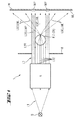
- Fig. 1 is a schematic plan view of an embodiment of the invention Device 1 for generating and projecting light marks.
- Main components of the device 1 are the light source device Q, the Kollimationsoptik K and the projection optics P.
- the light source device Q generates primary light in the form of a primary light beam L1.
- the collimation optics K takes at least part of the primary light beam L1 and forms from this a secondary light beam L2, which in comparison collimated to the primary light beam L1, parallelized and optionally is widened.
- the Kollimationsoptik K is the secondary Light beam L2 emitted or emitted in a directed manner. This is done in such a way that the projection optics P provided in the beam path at least partially irradiated.
- the projection optics P is the embodiment 1 essentially of a cylindrical lens Z. In Fig. 1 is a Cross section through the entire optical arrangement of the device according to the invention 1, so that the cylindrical lens Z of the projection optics P here in Form of a circle appears.
- the cylindrical lens Z is so with the secondary light beam L2 is applied to a cylinder section area ZA of the cylinder lens Z by a central beam L2Z of the secondary light beam L2 in Essentially completely irradiated.
- Edge beam L2R of the secondary light beam L2 am Mantle M of the cylindrical lens Z directly and in a substantially unhindered form past, in the form of an edge beam L3R of the tertiary light beam L3.
- the central beam L2Z of the secondary light beam L2 undergoes refraction interaction with the material of the Cylindrical lens Z of the projection optics P. This is the central beam L2Z scattered, widened or spread, so that the individual rays of the the cylinder lens Z leaving central beam L3Z substantially in a well-defined plane scattered across the room to measure.
- two marginal rays L2R and L3R, respectively, of the secondary light beam L2 and the tertiary light beam L3 are provided.
- These edge beams L2R, L3R lead in the application to the formation of dot marks MP, when an object, for. B. in the form of a wall W, is hit by the tertiary light beam L3.
- the so-called near field is shown, in which the two boundary beams L2R, L3R still lead to separated point marks MP.
- the corresponding line mark ML is also shown on the wall W, which is generated by the corresponding central beam L3Z of the tertiary light beam L3.
- the peripheral rays L3R of the tertiary light beam L3 thus form Beam LMP for point marks, while the central beam L3Z of the tertiary light beam L3, a beam LML for the line mark forms.
- a diaphragm device B To influence the geometry of the secondary light beam L2 and the corresponding edge beams L2R and central beams L2Z is in the embodiment 1 between the collimation optics K and the projection optics P a diaphragm device B is provided.
- FIG. 2 shows a structure similar to the construction of FIG. 1 for a device according to the invention Device 1 for generating and emitting light marks.
- the light source device Q consists of a laser diode or of a Laser diode array.
- the collimation optics is thereby more concrete, that here indicated the various optical input and output lens systems are.
- a diaphragm as in the embodiment of Fig. 1 is shown in the Kollimationsoptik K integrated designed provided.
- FIG. 3A shows in the form of a photograph the light marks projected onto the wall W. in the form of the line mark ML and in the form of the two point marks MP, like them already schematically indicated in Fig. 1.
- Fig. 3A shows the conditions of the radiation field in the near field, ie the so-called near field the intensity distribution.
- Fig. 3B illustrates the intensity distribution in the form of a photograph in the so-called far field, so comparatively far from the device 1 for generating and projecting light marks.
- FIGS. 4A to 5B illustrate various geometric relationships between the secondary light beam L2 of the diaphragm B or B used Aperture device B and the cylindrical lens Z of the projection optics P.
- the cylindrical lens Z of the Projection optics P is based on a circular cylinder, which as a base a Circle having the radius R has. Accordingly, in the following figures the cylindrical lens Z an effective or optical effective diameter D, which 2 times the radius R corresponds. All other information is therefore relative information Compared to the radius R of the cylindrical lens Z underlying circle base.
- the secondary light beam L2 has an elliptical cross section with a large semiaxis a and a small semi-axis b.
- the large semiaxis a is perpendicular to Symmetry axis X of the cylindrical lens Z oriented and corresponds approximately to 8 times Radius of the cylindrical lens Z or the simple optical effective diameter D of the cylindrical lens Z.
- the small semiaxis b of the secondary light beam L2 is aligned parallel to the axis of symmetry X of the cylindrical lens Z and corresponds in extent to twice the radius R of the cylindrical lens Z or the optical effective diameter D of the cylindrical lens Z.
- Fig. 4A is a circular aperture B with a diaphragm diameter Rkb used, which is twice the optical effective diameter D of the cylindrical lens Z, ie 4 times the radius of the cylindrical lens Z corresponds.
- the aperture B and the Secondary light beams L2 are arranged concentrically with each other. shown are also the marginal rays L2R of the secondary light beam L2, which run past the jacket M of the cylindrical lens Z. It is also recognizable Central beam L2Z of the secondary light beam L2, which the Cylinder section range ZA of the cylindrical lens Z of the projection optics P substantially completely irradiated.
- a rectangular diaphragm B is used in FIG. 4B.
- the cross section of the secondary light beam L2 formed concentric with the rectangular aperture.
- the major semi-axis a is the cross-section of the secondary light beam L2 aligned in parallel to the axis of symmetry X of the cylindrical lens Z and has an extension which is 12 times Radius R of the cylindrical lens Z or 6 times the optical effective diameter D corresponds to the cylindrical lens Z.
- the small semiaxis b of the cross section of the secondary light beam L2 is in each case perpendicular to the axis of symmetry X.
- the cylindrical lens Z is formed and has an extension which is 4 times Radius R of the cylindrical lens Z or the double optical effective diameter D corresponds to the cylindrical lens Z.
- a rectangular aperture B is provided, and although with a long edge c parallel or perpendicular to the axis of symmetry X the Cylindrical lens Z.
- the long edge c has an extension 4 times the radius R of the cylindrical lens (2 times the optical effective diameter D) or 6 times Radius of the cylindrical lens Z (3 times the optical effective diameter D) corresponds.
- FIGS. 7 to 10 show embodiments of the device 1 according to the invention for generating and projecting light marks, in which the cylindrical lens Z the projection optics P is based on a skew cylinder, with opposite the axis of symmetry X of the cylindrical lens Z by 45 ° inclined end surfaces A, which Moreover, such are mirrored and arranged that a part of the secondary Light beam L2 can be reflected on it so that perpendicular to the projection level for the line mark ML external and further point marks (MPe) can be projected and mapped.
- These additional and external Dot marks or spot marks MPe become over at the mirroring end faces A of the cylindrical lens Z reflected light beams LMMe mediates, as the in Fig. 7 is shown schematically.
- FIG. 8 shows a further schematic and sectional side view of FIG. 7 illustrated situation, which also provides further dimensioning information are.
- the diameter of the cylindrical lens Z is again denoted by R.
- the line mark for generating to project here has a height which dern 1.8 times the radius R of Cylindrical lens Z corresponds.
- Fig. 9 shows details with respect to the secondary light beam L2 and the Aperture B, as in a particular embodiment of the in Figs. 7 and 8 shown device 1 for generating and projecting light marks used could become.
- the large semiaxis a which is shown in FIG. 9 not shown, aligned parallel to the axis of symmetry X of the cylindrical lens Z. and has an extension which is 9 times the radius R of the cylindrical lens Z or 4.5 times the effective optical diameter D of the cylindrical lens Z equivalent.
- the small semiaxis b of the cross section of the secondary light beam L2 is extended perpendicular to the axis of symmetry X of the cylindrical lens Z. and has an extension of about 3 times the radius R of the cylindrical lens Z. or 1.5 times the effective optical diameter D of the cylindrical lens Z.
- the diaphragm B consists of a circular plate with three recesses B1, B2 and B3.
- the first recess B1 has Recheckform for generating the marginal rays L2R and the central beam L2Z to generate the actual Line mark ML and the actual point mark MP.
- Fig. 10 shows a perspective view from above of the conditions as they are can result in the application of the arrangement shown in FIGS. 7 to 9.
- the incident secondary light beam is L2 not shown.
- upper and lower end surfaces A are formed as mirrors.
- At these reflective end surfaces of the cylindrical lens Z are shares of here not shown secondary light beam L2 perpendicular to the top or down reflected, in the form of beams LMMe for trainee external point markers MPe.
- the phrase "vertical" refers to that plane, that of the tertiary beam L3Z or the line mark beam LML is formed. Shown are also the Dot marker bundle LMP, which again in the form of marginal rays L3Z of the tertiary beam L3 appear in appearance.
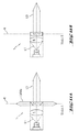
- FIGS. 11A and 11B show devices 1 according to the invention once again are formed in the form of modules A and B, in side cross-sectional views.
- the module A corresponds approximately to an embodiment, as they is shown in Figs. 7 to 10.
- module B essentially has the structure as shown in Figs. 1 to 6B.
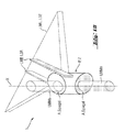
- Fig. 12 shows an arrangement of the modules A and B in the region of a positioning device 10.
- This positioning device 10 is formed by a Modulnlie G, z. B. in the form of a housing, in or on which the modules A and B, and optionally also other modules are attached and arranged.
- the order The modules A and B are such that the tertiary light beams L3 each spanned planes are approximately perpendicular to each other and that the straight lines defined by the respective dot mark beams LMP also perpendicular to each other.
- the housing or the module carrier G is attached to a shuttle thread F such that when vertically aligned of the pendulum thread F and the module carrier G formed pendulum, z. B. in the gravitational field of the earth, the shuttle thread F on the defined by the module A. Level is perpendicular and to the plane defined by the module B. runs parallel.
- FIGS. 13 to 14B describe possible positioning and orientations, as in the embodiment according to FIG. 1 to 6B or in the embodiment according to FIGS. 7 to 10 are conceivable.
- Fig. 13 an arrangement according to FIGS. 1 to 6B, three different assume basic positions to each other.
- the embodiment 7 to 10 are only two fundamentally different positions possible in two-dimensional space.
Abstract
Description
Die Erfindung betrifft eine Vorrichtung zum Erzeugen und Projizieren von Lichtmarken
gemäß dem Oberbegriff von Anspruch 1.The invention relates to a device for generating and projecting light marks
according to the preamble of
Es ist bekannt, bei Herstellungsverfahren, konstruktiven Maßnahmen oder auch bei Bauvorhaben Vorrichtungen einzusetzen, durch welche Lichtmarken in geeigneter Weise erzeugt und projiziert werden können. Diese Lichtmarken werden verwendet, um bei den oben erwähnten Vorgängen absolute oder relative Positionen, Orientierungen und dergleichen von Gegenständen, Räumlichkeiten oder Örtlichkeiten zu definieren und einem Benutzer anzuzeigen.It is known in manufacturing processes, constructive measures or also to use in construction projects devices through which light brands in appropriate Can be generated and projected. These lights become brands used in the above-mentioned operations absolute or relative positions, Orientations and the like of objects, premises or Define locations and display to a user.
Bekannte Vorrichtungen zum Erzeugen und Projizieren von Lichtmarken weisen dazu eine Lichtquelleneinrichtung, eine Kollimationsoptik sowie eine Projektionsoptik auf. Die Lichtquelleneinrichtung dient zur Erzeugung und Aussendung eines primären Lichtstrahlenbündels. Die Kollimationsoptik ist zum Empfang des primären Lichtstrahlenbündels und zu dessen Kollimation, Parallelisierung und dabei Aufweitung in ein sekundäres Lichtstrahlenbündel sowie zum gerichteten Aussenden des sekundären Lichtstrahlenbündels ausgebildet und vorgesehen. Die Projektionsoptik dient dem Empfang zumindest eines Teils des sekundären Lichtstrahlenbündels und der Wandlung des sekundären Lichtstrahlenbündels in zumindest ein für mindestens eine Lichtmarke geeignetes tertiäres Lichtstrahlenbündel oder Markierungsstrahlenbündel und deren Ausgabe und dabei zur Projektion mindestens einer Lichtmarke.Known devices for generating and projecting light marks have to a light source device, a collimating optics and a projection optics on. The light source device is used for generating and emitting a primary light beam. The collimation optics is to receive the primary Light beam and collimation, parallelization and thereby Expansion into a secondary beam of light and directional emission formed and provided the secondary light beam. The Projection optics serve to receive at least part of the secondary light beam and the conversion of the secondary light beam in at least a suitable for at least one light mark tertiary light beam or marking beams and their output and thereby to the projection at least one light mark.
Dabei ist nachteilig, dass nur durch einen erheblichen Aufwand simultan sowohl Linienmarkierungen, also Lichtmarken in Form einer Linie, als auch Punkt- oder Fleckmarkierungen, also Lichtmarken in Form eines Punkts oder Flecks, erzeugt und projiziert werden können. In der Regel sind dazu mehrere voneinander unabhängig betreibbare und doch aufeinander zu justierende und abzustimmende Projektionseinheiten mit entsprechenden Optiken notwendig.It is disadvantageous that only by a considerable effort both simultaneously Line markings, so light marks in the form of a line, as well as point or Fleck marks, so light marks in the form of a dot or spot generated and can be projected. As a rule, several are independent of each other operable and yet to be adjusted and reconciled Projection units with corresponding optics necessary.
Der Erfindung liegt die Aufgabe zugrunde, eine Vorrichtung zum Erzeugen und Projizieren von Lichtmarken der eingangs erwähnten Art derart fortzubilden, dass auf besonders einfache und gleichwohl zuverlässige Art und Weise simultan gut sichtbare Punktmarken und Linienmarken mit besonders geringem optischem Aufwand und unter weitestgehender Vermeidung von Justagevorgängen erzeugbar und projizierbar sind. The invention has for its object to provide a device for generating and Projecting of light marks of the type mentioned in such a way that good and easy in a very simple and yet reliable way visible point marks and line marks with particularly low optical Expenditure and generated as far as possible avoid adjustment operations and are projectable.
Die Aufgabe wird bei einer Vorrichtung zum Erzeugen und Projizieren von Lichtmarken
der eingangs erwähnten Art erfindungsgemäß mit den kennzeichnenden
Merkmalen des Anspruchs 1 gelöst. Vorteilhafte Weiterbildungen der erfindungsgemäßen
Vorrichtung zum Erzeugen und Projizieren von Lichtmarken sind Gegenstand
der abhängigen Unteransprüche.The object is in a device for generating and projecting light marks
of the type mentioned according to the invention with the characterizing
Characteristics of
Die erfindungsgemäße Vorrichtung zum Projizieren von Lichtmarken ist allgemein dadurch gekennzeichnet, dass die Projektionsoptik mit dem sekundären Lichtstrahlenbündel oder einem Teil davon derart beaufschlagbar ist, dass ein Bereich der Projektionsoptik im Wesentlichen von einem Zentralstrahlenbündel des sekundären Lichtstrahlenbündels im Wesentlichen vollständig derart durchstrahlbar ist und dass mindestens ein Randstrahlenbündel des sekundären Lichtstrahlenbündels benachbart zum Zentralstrahlenbündel des sekundären Lichtstrahlenbündels unmittelbar am Rand oder Mantel der Projektionsoptik vorbei derart aussendbar ist, dass das Zentralstrahlenbündel des sekundären Lichtstrahlenbündels durch Wechselwirkung mit der Projektionsoptik zerstreubar und als Teil des tertiären Lichtstrahlenbündels oder als Linienmarkenstrahlenbündel für eine Lichtmarke im Wesentlichen in Form einer Linie projizierbar ist und dass das mindestens eine Randstrahlenbündel des sekundären Lichtstrahlenbündels als Teil des tertiären Lichtstrahlenbündels oder als Punktmarkenstrahlenbündel für eine Lichtmarke im Wesentlichen in Form eines Punkts oder eines Flecks projizierbar ist.The inventive device for projecting light marks is general characterized in that the projection optics with the secondary light beam or part of it is acted upon such that an area the projection optics essentially of a central beam of the secondary Light beam essentially completely durchstrahlbar in such a way is and that at least one edge beam of the secondary light beam adjacent to the central beam of the secondary light beam directly on the edge or mantle of the projection optics passing out such a way is that the central beam of the secondary light beam dispersible by interaction with the projection optics and as part of the tertiary light beam or as a line marker beam for a Light mark is essentially projected in the form of a line and that the at least one marginal ray bundle of the secondary light beam as Part of the tertiary light beam or as a spot mark beam for a light mark can be projected substantially in the form of a dot or spot is.
Eine bevorzugte Ausführungsform der erfindungsgemäßen Vorrichtung zum Projizieren von Lichtmarken ist dadurch gekennzeichnet, dass die Projektionsoptik eine Zylinderlinse aufweist. Ferner ist die Zylinderlinse mit dem sekundären Lichtstrahlenbündel oder dem Teil davon derart beaufschlagbar, dass ein Zylinderabschnittsbereich der Zylinderlinse als der Bereich der Projektionsoptik im Wesentlichen von einem Zentralstrahlenbündel des sekundären Lichtstrahlenbündels für die Lichtmarke im Wesentlichen in Form einer Linie im Wesentlichen vollständig durchstrahlbar ist und dass mindestens ein Randstrahlenbündel des sekundären Lichtstrahlenbündels für die Lichtmarke im Wesentlichen in Form eines Punkts oder eines Flecks benachbart zum Zentralstrahlenbündel des sekundären Lichtstrahlenbündels unmittelbar am Rand oder Mantel des Zylinderabschnitts als Rand oder Mantel des Bereichs der Projektionsoptik vorbei aussendbar ist.A preferred embodiment of the device according to the invention for projecting of light marks is characterized in that the projection optics having a cylindrical lens. Furthermore, the cylindrical lens is with the secondary Light beam or the part thereof acted upon such that a cylinder portion area the cylindrical lens as the area of the projection optics in Essentially from a central beam of the secondary light beam for the light mark substantially in the form of a line substantially is completely durchstrahlbar and that at least one edge of the beam secondary light beam for the light mark substantially in shape a spot or spot adjacent to the central beam of the secondary Light beam directly on the edge or mantle of the cylinder portion as a border or coat of the area of the projection optics broadcastable by is.
Auf diese Weise werden unter Verwendung einer einzigen Lichtquelleneinrichtung mit einer einzigen Projektionsoptik mit oder in Form einer Zylinderlinse simultan sowohl eine Lichtmarke in Form einer Linie, nämlich eine Linienmarke, als auch eine Lichtmarke in Form eines oder zweier Punkte, nämlich eine Punktmarke, erzeugbar und projizierbar. Aufgrund der fixierten Geometrie durch Verwendung einer einzigen Zylinderlinse haben die Linienmarke und die Punktmarke oder die Punktmarken zueinander eine vorgegebene räumliche Beziehung, ohne dass es dazu einer Justage bedarf. Weiterhin ist bei der erfindungsgemäßen Vorrichtung die Anzahl optischer Komponenten gegenüber herkömmlichen Vorgehensweisen reduziert, so dass sich hier ein verringerter Wartungsaufwand und auch reduzierte Kosten bei der Herstellung und Instandhaltung einer derartigen Vorrichtung ergeben.In this way, using a single light source device with a single projection optic with or in the form of a cylindrical lens simultaneously both a light mark in the form of a line, namely a line mark, as well a light mark in the form of one or two points, namely a point mark, can be generated and projectable. Due to the fixed geometry by use a single cylindrical lens have the line mark and the dot mark or Point marks to each other a given spatial relationship without it this requires an adjustment. Furthermore, in the device according to the invention the number of optical components compared to conventional approaches reduced, so that here reduced maintenance and reduced Costs in the manufacture and maintenance of such a device result.
Ein Aspekt der Erfindung ist somit, eine in der Projektionsoptik vorgesehen Zylinderlinse mit einem Lichtstrahlenbündel, welches sich aus einem primären Lichtstrahlenbündel durch Kollimation, Parallelisierung und Aufweitung als sekundäres Lichtstrahlenbündel ergibt, derart zu bestrahlen und mit diesem zu beaufschlagen, dass ein Teil des sekundären Lichtstrahlenbündels, nämlich ein Zentralstrahlenbündel einen Teil der Zylinderlinse, nämlich einen Zylinderabschnittsbereich davon oder ein Zylindersegment davon, im Wesentlichen vollständig durchstrahlt und dass ein anderer Teil des sekundären Lichtstrahlenbündels, nämlich mindestens ein Randstrahlenbündel unmittelbar am Rand oder Mantel der Zylinderlinse, nämlich des Zylinderabschnittsbereichs, welcher im Wesentlichen vollständig durchstrahlt wird, vorbeiläuft oder vorbei aussendbar ist. Das Zentralstrahlenbündel wird durch Wechselwirkung oder Brechung mit dem durchstrahlten Zylinderabschnittsbereich zerstreut oder dispergiert, so dass sich nach Durchgang durch den Zylinderabschnittsbereich oder durch das Zylindersegment in der Anwendung oder im Betrieb auf einer entfernten Projektionsfläche eine Lichtmarke in Form einer Linie oder eine Linienmarke ergibt. Die Randstrahlenbündel oder das Randstrahlenbündel verlaufen oder verläuft außen am Mantel an der Zylinderlinse im Bereich des Zylinderabschnitts vorbei und bildet somit im Betrieb und in der Anwendung auf einer dann vorgesehenen Projektionsfläche eine entsprechende Punktmarke, also eine Lichtmarke in Form eines Punkts oder Flecks. Durch eine entsprechende Ausgestaltung können die Punktmarke und die Linienmarke in eine bestimmte räumliche Relation zueinander gesetzt werden, so dass sich z. B. auf der Linienmarke durch die Punktmarke ein bestimmter räumlicher Referenzpunkt definieren und darstellen lässt.One aspect of the invention is thus a cylindrical lens provided in the projection optics with a light beam, which consists of a primary beam of light through collimation, parallelization and expansion as secondary Light beam results in such irradiation and apply to this, that a part of the secondary light beam, namely a central beam a part of the cylindrical lens, namely a cylinder portion area thereof or a cylinder segment thereof, substantially complete radiates through and that another part of the secondary light beam, namely at least one edge beam directly on the edge or mantle the cylinder lens, namely the cylinder portion area, which is substantially is completely irradiated, passed by or can be sent out. The Central beam is irradiated by interaction or refraction with the Cylinder section area scattered or dispersed, so that after Passage through the cylinder portion area or through the cylinder segment in use or in operation on a remote projection screen one Light mark in the form of a line or a line mark results. The marginal beams or the edge beam or run on the outside of the jacket the cylindrical lens in the region of the cylinder section over and thus forms in Operation and in the application on a projection surface then provided a corresponding point mark, ie a light mark in the form of a dot or Spot. By a corresponding embodiment, the point mark and the Line mark are placed in a particular spatial relation to each other, so that z. B. on the line mark by the point mark a certain spatial Define reference point and display.
Dies alles ist beim Stand der Technik wenn überhaupt nur mit einem erheblichen Mehraufwand mit einer Mehrzahl von Projektionssystemen, nämlich für jede Lichtmarke oder für jeden Lichtmarkentyp ein separates, möglich. All this is in the state of the art, if at all only with a considerable Extra effort with a plurality of projection systems, namely for each Light brand or for each type of light mark a separate, possible.
Besonders vorteilhafte Projektions- und Abbildungsverhältnisse ergeben sich dann, wenn die Lichtquelleneinrichtung gemäß einer bevorzugten Ausführungsform der erfindungsgemäßen Vorrichtung zur Erzeugung und Aussendung im Wesentlichen kohärenten und/oder monochromatischen Lichts für das primäre Lichtstrahlenbündel ausgelegt ist. Dann nämlich stellen sich besonders scharfe Abbildungsverhältnisse im Betrieb ein.Particularly advantageous projection and imaging conditions arise when the light source device according to a preferred embodiment the device according to the invention for generating and emitting substantially coherent and / or monochromatic light for the primary Light beam is designed. Then that's when you get really sharp Imaging conditions in operation.
Unter bestimmten symmetrischen Verhältnissen ist es auch dann möglich, bei der Verwendung zweier Randstrahlenbündel, welche im Betrieb an gegenüberliegenden Randbereichen des Zylinderabschnittsbereichs vorbeilaufen, im Fernfeld des Lichtstrahlungsfeldes eine Interferenz zweier im Nahfeld noch getrennter Punktmarken zu einer einzigen gemeinsamen Punktmarke zu erreichen. Dies hat insbesondere im Hinblick auf die Helligkeit und damit die Wahrnehmbarkeit der Punktmarke Vorteile.Under certain symmetrical conditions, it is possible even at the Use of two peripheral beams, which in operation at opposite Run past edge areas of the cylinder section area, in the far field of Light radiation field, an interference of two in the near field still separate point marks to achieve a single common point mark. This has particular in terms of brightness and thus the perceptibility of the Point mark advantages.
Zur Erzeugung kohärenten und/oder monochromatischen Lichts sind verschiedene Realisationen oder Ausführungsformen für die Lichtquelleneinrichtung denkbar.To generate coherent and / or monochromatic light are different Realizations or embodiments for the light source device conceivable.
Vorteilhaft ist, wenn die Lichtquelleneinrichtung eine Laserlichtquelle aufweist oder von einer solchen gebildet wird. Diese kann monochromatisches kohärentes Licht mit einer hohen Intensität erzeugenIt is advantageous if the light source device has a laser light source or is formed by such. This can be monochromatic coherent Create light with a high intensity
Dabei ist grundsätzlich jegliche Laserlichtquelle einsetzbar, wobei besonders vorteilhaft die Verwendung einer Laserdiode oder einer Anordnung einer Mehrzahl Laserdioden als Lichtquelleneinrichtung oder im Bereich davon ist. Diese sind besonders kompakt und besitzen einen vergleichsweise geringen Energiebedarf.In principle, any laser light source can be used, with particular advantage the use of a laser diode or an array of a plurality Laser diode as a light source device or in the range thereof. These are particularly compact and have a relatively low energy consumption.
Starken Einfluss auf die Qualität im Hinblick auf Helligkeit, Kontrast und Abbildungsschärfe bei den Lichtmarken hat die Strahlform des sekundären Lichtstrahlenbündels, welches ja mit der Projektionsoptik wechselwirkt. Dazu ist in vorteilhafter Weise bei einer weiteren Ausführungsform der erfindungsgemäßen Vorrichtung zur Strahlformung bezüglich des sekundären Lichtstrahlenbündels zwischen der Kollimationsoptik und der Projektionsoptik eine Blendeneinrichtung vorgesehen. Diese Blendeneinrichtung gibt dem sekundären Lichtstrahlenbündel eine bestimmte symmetrische Form und räumliche Ausdehnung. Die Blendeneinrichtung kann auch Teil der Kollimationsoptik sein. Strong influence on the quality in terms of brightness, contrast and sharpness of image in the case of the light marks, the beam shape of the secondary light beam, which interacts with the projection optics. This is in Advantageously, in a further embodiment of the invention Apparatus for beam shaping with respect to the secondary light beam between the collimating optics and the projection optics an aperture device intended. This diaphragm device gives the secondary light beam a certain symmetrical shape and spatial extent. The aperture device can also be part of the collimation optics.
Die Blendeneinrichtung kann bei bestimmten Anwendungen als Kreisblende oder als Blende in Form einer Ellipse ausgebildet sein. Denkbar sind aber auch Rechteckblenden. Diese Formen können die Blendeneinrichtung selbst bilden oder sie können als Bestandteile einer Blendeneinrichtung mit einer Mehrzahl von Blenden und gegebenenfalls weiteren Komponenten vorhanden sein.The aperture device can be used as a circular shutter or in certain applications be designed as a diaphragm in the form of an ellipse. But also conceivable are rectangular panels. These shapes can form the aperture device itself or it can be used as components of a diaphragm device with a plurality of diaphragms and optionally other components.
Besonders vorteilhaft ist es dabei, wenn die jeweilige Blendeneinrichtung, z. B. als eine Kreisblende oder eine Rechteckblende, in Bezug auf den Querschnitt des zu begrenzenden sekundären Lichtstrahlenbündels konzentrisch ausgebildet und angeordnet ist. Das bedeutet, dass die jeweilige Blendeneinrichtung einen geometrischen Mittelpunkt oder Schwerpunkt besitzt und dass dieser geometrische Mittelpunkt oder Schwerpunkt mit dem geometrischen Mittelpunkt oder Schwerpunkt des Querschnitts des sekundären Lichtstrahlenbündels in etwa übereinstimmt.It is particularly advantageous if the respective aperture device, for. B. as a circular aperture or a rectangular aperture, in relation to the cross section of the limiting secondary beam of light concentric and is arranged. This means that the respective aperture device has a geometric Has center or center of gravity and that this geometric center or center of gravity with the geometric center or center of gravity of the cross section of the secondary light beam is approximately coincident.
Bei der Zylinderlinse für die Projektionsoptik bieten sich grundsätzlich sämtliche Zylinderformen an. Besonders vorteilhaft aufgrund seiner Einfachheit ist jedoch die Grundform eines Kreiszylinders. Entsprechend ist bei einer besonders bevorzugten Ausführungsform der erfindungsgemäßen Vorrichtung die Zylinderlinse in Form eines Kreiszylinders ausgebildet und besitzt insbesondere einen entsprechenden Kreisradius R für die zugrunde liegende Kreisgrundfläche und eine entsprechende Symmetrieachse X, bezüglich der die Zylinderlinse rotationssymmetrisch ausgebildet ist.In the cylinder lens for the projection optics are basically all Cylinder shapes. However, it is particularly advantageous because of its simplicity the basic shape of a circular cylinder. Accordingly, in a particularly preferred Embodiment of the device according to the invention, the cylindrical lens in Formed a circular cylinder and in particular has a corresponding Circle radius R for the underlying circular area and a corresponding circle Symmetry axis X, with respect to the cylindrical lens rotationally symmetric is trained.
Zur weiteren Konkretisierung des erfindungsgemäßen Prinzips werden die Größenverhältnisse der einzelnen optischen Komponenten, der jeweiligen Strahlenbündel und der verwendeten Lichtwellenlänge oder Lichtwellenlängen geeignet gewählt ausgebildet.To further concretize the principle of the invention, the size ratios the individual optical components, the respective beam and the wavelengths of light or wavelengths of light used chosen trained.
Die Zylinderlinse besitzt z. B. einen optischen Wirkdurchmesser D. Dieser ist, insbesondere in Bezug auf das sekundäre Lichtstrahlenbündel, in etwa identisch mit dem doppelten Radius R der zugrunde liegenden Kreisgrundfläche, wenn der Zylinderlinse ein Kreiszylinder zugrunde gelegt ist.The cylindrical lens has z. B. an optical effective diameter D. This is, especially with respect to the secondary light beam, approximately identical with the double radius R of the underlying circle base area, if the Cylindrical lens is a circular cylinder is used.
Bei einer besonders vorteilhaften Ausführungsform der erfindungsgemäßen Vorrichtung ist durch Wahl der Art und/oder der Geometrie der Lichtquelleneinrichtung, der Kollimationsoptik und/oder deren geometrischer und/oder Lagebeziehung zueinander das sekundäre Lichtstrahlenbündel mit einem im Wesentlichen elliptischen Querschnitt ausbildbar. Dieser hat insbesondere eine bestimmte große Halbachse a und eine bestimmte kleine Halbachse b. In a particularly advantageous embodiment of the device according to the invention is by choice of the type and / or the geometry of the light source device, the Kollimationsoptik and / or their geometric and / or positional relationship to each other, the secondary light beam having a substantially elliptical cross section can be formed. This particular has a certain large Half-axis a and a certain small semi-axis b.
Bei einer Ausführungsform der erfindungsgemäßen Vorrichtung ist es vorgesehen, dass die große Halbachse a des Querschnitts des sekundären Lichtstrahlenbündels in etwa senkrecht zur Symmetrieachse X der Zylinderachse verlaufend gewählt und ausgebildet ist.In one embodiment of the device according to the invention, it is provided that the large semiaxis a of the cross section of the secondary light beam chosen to be approximately perpendicular to the axis of symmetry X of the cylinder axis extending and trained.
Dann ist es von Vorteil, dass die große Halbachse a des Querschnitts des sekundären Lichtstrahlenbündels in etwa dem 8-fachen Radius R der Zylinderlinse bzw. dem 4-fachen optischen Wirkdurchmesser D der Zylinderlinse entspricht. Zusätzlich oder alternativ ist dabei vorgesehen dass die kleine Halbachse b des Querschnitts des sekundären Lichtstrahlenbündels in etwa dem 2-fachen Radius R der Zylinderlinse bzw. dem 1-fachen Wirkdurchmesser der Zylinderlinse entspricht.Then it is advantageous that the large semiaxis a of the cross section of the secondary Light beam in about 8 times the radius R of the cylindrical lens or corresponds to 4 times the optical effective diameter D of the cylindrical lens. additionally or alternatively, it is provided that the small semiaxis b of the cross section of the secondary light beam about 2 times the radius R of the Cylindrical lens or the 1-fold effective diameter of the cylindrical lens corresponds.
Bei einer weiteren Ausführungsform der erfindungsgemäßen Vorrichtung wird dann eine Kreisblende vorgesehen, deren Radius Rkb etwa dem 4-fachen Radius R der Zylinderlinse bzw. etwa dem 2-fachen optischen Wirkdurchmesser D der Zylinderlinse entspricht. Alternativ kann eine Rechteckblende vorgesehen sein, welche eine erste Kante c senkrecht zur Symmetrieachse X der Zylinderlinse aufweist, die etwa dem 3-fachen Radius R der Zylinderlinse bzw. dem 1, 5-fachen optischen Wirkdurchmesser D der Zylinderlinse entspricht, und welche eine zweite Kante d parallel zur Symmetrieachse X der Zylinderlinse aufweist, welche etwa dem 5-fachen Radius der Zylinderlinse bzw. etwa dem 2,5-fachen optischen Wirkdurchmesser D der Zylinderlinse entspricht.In a further embodiment of the device according to the invention is then provided a circular aperture whose radius Rkb is about 4 times the radius R the cylindrical lens or about 2 times the optical effective diameter D of the cylindrical lens equivalent. Alternatively, a rectangular shutter may be provided, which has a first edge c perpendicular to the axis of symmetry X of the cylindrical lens, about 3 times the radius R of the cylindrical lens or the 1.5 times optical Effective diameter D of the cylindrical lens corresponds, and which a second Edge d parallel to the axis of symmetry X of the cylindrical lens has, which approximately 5 times the radius of the cylindrical lens or about 2.5 times the effective optical diameter D corresponds to the cylindrical lens.
Bei einer alternativen Ausführungsform der erfindungsgemäßen Vorrichtung ist es vorgesehen, dass die große Halbachse a des Querschnitts des sekundären Lichtstrahlenbündels in etwa parallel zur Symmetrieachse X der Zylinderlinse verlaufend gewählt und ausgebildet ist.In an alternative embodiment of the device according to the invention it is provided that the large semiaxis a of the cross section of the secondary light beam extending approximately parallel to the axis of symmetry X of the cylindrical lens chosen and trained.
Bei dieser Variante ist es dann von besonderem Vorteil, wenn die große Halbachse a des Querschnitts des sekundären Lichtstrahlenbündels in etwa dem 12-fachen Radius R der Zylinderlinse bzw. etwa dem 6-fachen optischen Wirkdurchmesser D der Zylinderlinse entspricht. Alternativ oder zusätzlich ist es dann vorgesehen, dass die kleine Halbachse b des Querschnitts des sekundären Lichtstrahlenbündels in etwa dem 4-fachen Radius R der Zylinderlinse bzw. etwa dem 2-fachen Wirkdurchmesser D der Zylinderlinse entspricht.In this variant, it is particularly advantageous if the large semi-axis a of the cross section of the secondary light beam is approximately 12 times Radius R of the cylindrical lens or about 6 times the optical effective diameter D the cylindrical lens corresponds. Alternatively or additionally, it is then provided that the small semiaxis b of the cross section of the secondary light beam in about 4 times the radius R of the cylindrical lens or about twice Effective diameter D of the cylindrical lens corresponds.
Auch bei dieser Ausführungsform der erfindungsgemäßen Vorrichtung sind eine Kreisblende oder alternativ eine Rechteckblende denkbar. Also in this embodiment of the device according to the invention are a Circle or alternatively a rectangular cover conceivable.
Bei der Verwendung einer Kreisblende ist es von Vorteil, wenn deren Radius Rkb etwa dem 4-fachen oder dem 6-fachen Radius R der Zylinderlinse bzw. etwa dem 2-fachen bzw. etwa dem 3-fachen optischen Wirkdurchmesser D der Zylinderlinse entspricht.When using a circular shutter, it is advantageous if its radius Rkb about 4 times or 6 times the radius R of the cylindrical lens or about the 2 times or about 3 times the optical effective diameter D of the cylindrical lens equivalent.
Bei der Verwendung der Rechteckblende weist diese eine erste Kante c senkrecht zur Symmetrieachse X der Zylinderlinse auf, welche etwa dem 3-fachen oder etwa dem 6-fachen Radius R der Zylinderlinse bzw. etwa dem 1,5-fachen oder etwa dem 3-fachen optischen Wirkdurchmesser D der Zylinderlinse entspricht. Ferner besitzt die Rechteckblende eine zweite Kante d parallel zur Symmetrieachse X der Zylinderlinse, und zwar entsprechend etwa dem 4-fachen Radius R der Zylinderlinse bzw. etwa dem 2-fachen optischen Wirkdurchmesser D der Zylinderlinse.When using the rectangular shutter, this has a first edge c vertically to the axis of symmetry X of the cylindrical lens, which is about 3 times or about the 6-fold radius R of the cylindrical lens or about 1.5 times or about the 3 times the optical effective diameter D of the cylindrical lens corresponds. Furthermore owns the rectangular aperture a second edge d parallel to the axis of symmetry of the X Cylindrical lens, and corresponding to about 4 times the radius R of the cylindrical lens or about 2 times the optical effective diameter D of the cylindrical lens.
Die bisher beschriebenen Ausführungsformen sind dazu geeignet, eine Linienmarke auszubilden, auf der sich als Bezugspunkt ein oder zwei Punktmarken darstellen lassen.The embodiments described so far are suitable for a line mark form on which as a reference point one or two point marks to let.
Bei einer besonders bevorzugten Ausführungsform der erfindungsgemäßen Vorrichtung wird jedoch die Zylinderlinse in Form eines Schiefzylinders ausgebildet, wobei mindestens eine gegenüber der Symmetrieachse X der Zylinderlinse geneigte Grundfläche A oder Endfläche A vorgesehen ist. Diese geneigte Grundfläche A oder Endfläche A wird verspiegelt ausgebildet vorgesehen. Die Anordnung ist dabei so gewählt, dass durch die verspiegelte Grundfläche A oder Endfläche A zumindest ein Teil des sekundären Lichtstrahlenbündels derart reflektierbar ist, dass außerhalb der Ebene, welche durch die Vorrichtung selbst und durch das tertiäre Lichtstrahlenbündel für die Lichtmarke gebildet wird, eine externe und weitere Lichtmarke im Wesentlichen in Form eines Punkts oder Flecks abbildbar oder projizierbar ist.In a particularly preferred embodiment of the device according to the invention However, the cylindrical lens is formed in the form of a slant cylinder, wherein at least one inclined relative to the axis of symmetry X of the cylindrical lens Base A or end face A is provided. This inclined base A or end surface A is provided formed mirrored. The arrangement is chosen so that through the mirrored base A or end face A at least a part of the secondary light beam is so reflective, that outside the plane passing through the device itself and through the tertiary light beam is formed for the light mark, an external and another light mark essentially in the form of a dot or spot can be mapped or projectable.
Durch diese Maßnahme wird also erreicht, dass aus der Projektionsebene für die Linienmarke heraus, z. B. aber nicht ausschließlich senkrecht dazu, eine Punktmarke nach oben oder nach unten heraus abgebildet oder projiziert wird. So kann z. B. in der Anwendung die Linienmarke an eine Wand eines Raums in einem Gebäude projiziert werden, während die zusätzliche oder weitere Punktmarke an der Decke oder am Boden erscheint und als weitere Referenz dient.By this measure is thus achieved that from the projection plane for the Line mark out, z. But not exclusively perpendicular thereto, a dot mark imaged or projected outwards or downwards. So can z. B. in the application, the line mark on a wall of a room in a building projected while the additional or further point mark on the Ceiling or on the ground appears and serves as another reference.
Bei einer besonders vorteilhaften Ausbildung der erfindungsgemäßen Vorrichtung sind beide Grundflächen A oder Endflächen A der Zylinderlinse geneigt, verspiegelt und derart ausgebildet, dass zwei externe und weitere Lichtmarken im Wesentlichen in Form eines Punkts oder Flecks abbildbar oder projizierbar sind.In a particularly advantageous embodiment of the device according to the invention both base surfaces A or end surfaces A of the cylindrical lens are inclined, mirrored and formed such that two external and further light marks substantially in the form of a dot or spot can be imaged or projected.
Herkömmlicherweise können Linienmarken z. B. als eine Reihe von diskreten Punkten mit Hilfe von diffraktiven Elementen erzeugt werden. Der Nachteil dabei ist, dass die Linie nicht kontinuierlich ist. Eine andere konventionelle Linienmarke wird durch eine einfache Zylinderlinse produziert. Der Nachteil ist, dass die Intensität auf einer breiten Linie verteilt ist, so dass die Linie bei großer Entfernung in bestimmten Lichtverhältnissen der Umgebung nicht mehr gut sichtbar ist. Auf der Linie ist kein Bezugspunkt zu erkennen, welcher aber in vielen Fällen gewünscht ist. Zum Beispiel, wenn die Linie senkrecht ausgerichtet ist, um einen nivellierten Punkt auf der Linie festzustellen.Conventionally, line marks z. As a series of discrete ones Points are generated by means of diffractive elements. The disadvantage here is that the line is not continuous. Another conventional line brand is produced by a simple cylindrical lens. The downside is that the Intensity is distributed on a wide line, making the line at great distance in certain lighting conditions of the environment no longer clearly visible is. There is no reference point on the line, but in many cases is desired. For example, if the line is vertically aligned to one determine leveled point on the line.
Eine Idee der Erfindung ist, die Abbildung eines Bezugspunktes auf eine Linienmarke in großer Entfernung zu ermöglichen, ohne auf die Kontinuität der Linie zu verzichten. Dies wird durch die erfindungsgemäße Vorrichtung erreicht.One idea of the invention is the mapping of a reference point to a line mark to allow at a great distance without giving up the continuity of the line without. This is achieved by the device according to the invention.
Der Durchmesser des kollimierten oder in einer bestimmten Entfernung fokussierten Laserstrahls ist größer als der optische Wirkdurchmesser der Zylinderlinse. So können sich zwei Randbereiche des kollimierten Laserstrahls ungehindert weiter nach vorne ausbreiten. Im Nahfeld werden eine Linie und zwei Punkte um das Zentrum gebildet. Ab einem bestimmten Abstand von der Zylinderlinse, welcher vom Außendurchmesser der Zylinderlinse abhängig ist, also im Fernfeld, werden die beiden Randstrahlenbündel der Punkte zu einem Punkt interferieren.The diameter of the collimated or focused at a certain distance Laser beam is greater than the optical effective diameter of the cylindrical lens. Thus, two edge regions of the collimated laser beam can be unhindered continue to spread forward. In the near field, one line and two points are reversed the center formed. From a certain distance from the cylindrical lens, which depends on the outer diameter of the cylindrical lens, ie in the far field, the two marginal beams of the points will interfere to one point.
Der Strahldurchmesser und die Blende können bestimmte Formen annehmen und an den Rändern des Hauptlaserstrahls so gestaltet werden, dass die Bildung des Punktes im Fernfeld beeinflusst wird.The beam diameter and the aperture can take certain forms and be designed at the edges of the main laser beam so that the formation of the Point in the far field is affected.
Die Blenden können in Form eines Kreises oder Rechtecks ausgebildet sein.The panels may be in the form of a circle or rectangle.
Die Großachse oder große Halbachse a des Laserstrahls kann senkrecht zur Zylinderlinsenachse Z stehen.The major axis or large semiaxis a of the laser beam can be perpendicular to the cylindrical lens axis Z stand.
Z. B. kann der Randstrahl durch eine Kreisblende geschnitten werden, so dass die eine Seite des Randstrahls eine Krümmung bekommt, d. h. der Randstrahl nimmt eine unsymmetrische Form an. Dagegen wird der Randstrahl durch eine Rechteckblende annähernd symmetrisch. Das Beugungsbild wird dadurch bessere Symmetrie aufweisen.For example, the marginal ray can be cut through a circular aperture, so that the one side of the marginal ray gets a curvature, d. H. the marginal ray takes an asymmetrical shape. In contrast, the marginal ray is a rectangular aperture approximately symmetrical. The diffraction image will be better Have symmetry.
Einfluss der Blendengröße: Je größer die Blendendurchmesser bzw. je länger die Breite des Rechtecks wird, desto schmaler erscheint das Beugungsbild in horizontaler Richtung, d. h. es ergibt sich eine bessere Ortsauflösung in horizontaler Richtung.Influence of the aperture size: The larger the aperture diameter or the longer the Width of the rectangle becomes, the narrower the diffraction image appears in horizontal Direction, d. H. it results in a better spatial resolution in horizontal Direction.
Die Großachse oder große Halbachse a der Ellipse des Querschnitts des sekundären Lichtstrahlenbündels des Laserstrahls kann auch parallel zur Zylinderachse der Zylinderlinse stehen. Diese Ausführungsformen werden auch als Line-Dot-Laser bezeichnet. Dann hat die Blendenform mehr Einfluss auf das Beugungsbild als die Blendengröße, weil die Breite des Laserstrahls in diesen Fällen bedingt beschränkt ist. Der Versuch, die Breite zu vergrößern, bringt den großen Nachteil des Energieverlustes mit sich, damit leidet auch die Sichtbarkeit der Linienmarke.The major axis or semi-major axis a of the ellipse of the cross section of the secondary Light beam of the laser beam can also be parallel to the cylinder axis the cylindrical lens stand. These embodiments are also called line-dot lasers designated. Then the aperture shape has more influence on the diffraction pattern as the aperture size, because the width of the laser beam in these cases requires is limited. The attempt to increase the width brings the big disadvantage energy loss, the visibility of the line mark also suffers.
Es können zusätzlich zwei in entgegen gesetzten Richtungen ausgerichtete Punktstrahlen für externe Punktmarken vorgegeben werden durch zwei Spiegelflächen integriert auf der Zylinderlinse. Die beiden Enden der Zylinderlinse sind dann mit Spiegelflächen versehen, welche z. B. 45° zur Zylinderachse liegen. Außerdem liegen sie 90° zueinander. Diese Ausführungsform wird auch als Line- Multibeam-Laser bezeichnet.There may additionally be two spot beams aligned in opposite directions for external point marks are given by two mirror surfaces integrated on the cylindrical lens. The two ends of the cylindrical lens are then with Mirror surfaces provided which z. B. 45 ° to the cylinder axis. In addition, lie they are 90 ° to each other. This embodiment is also called a line multibeam laser designated.
Die Großachse a der Ellipse des Laserstrahls kann dann parallel zur Verbindungslinie zweier runder Blenden ausgerichtet sein. An den beiden 45°-Spiegelflächen A werden zwei Teilstrahlen um 90° umgelenkt. Die kurze Seite (bzw. die Breite) b des Querschnitts des Laserstrahls muss größer sein als der Durchmesser D der Zylinderlinse, so dass sich ein Teil des Laserstrahls vorbei an beiden Seiten der Zylinderlinse weiter ausbreiten kann. Die zwei auf diese Weise erzeugten Strahlenpunkte stehen 90°-senkrecht auf der Fläche, welche der Linienlaser aufspannt.The major axis a of the ellipse of the laser beam can then be parallel to the connecting line be aligned with two round aperture. At the two 45 ° mirror surfaces A, two partial beams are deflected by 90 °. The short side (or the width) b of the cross section of the laser beam must be greater than that Diameter D of the cylindrical lens, so that a part of the laser beam passing both sides of the cylinder lens can continue to spread. The two in this way generated beam points are 90 ° perpendicular to the surface, which is the line laser spans.
Es kann in einem Gerät auch eine Kombination aus Line-Dot- und Line-Multibeam-Laser vorgesehen sein, wie das in Fig. 12 gezeigt ist. Es besteht aus einem Modul A als Line-Multibeam-Laser und einem Modul B als Line-Dot-Laser. Die beiden Module sind auf einem Träger befestigt so, dass die beiden Linienmarken der Module A und B senkrecht zueinander stehen, wobei die zwei Punktmarken nach oben und unten im Lot zeigen. Die Punktlaser von Module A und B bilden ein rechtwinkliges Koordinatensystem und haben gleichen Ursprung (Koinzidenz). Der ganze Aufbau ist an einem Pendel, beispielsweise an einer stabilen Schnur oder Faden, aufgehängt. Durch Wirkung der Schwerkraft ist der ganze Aufbau im Lot ausgerichtet und kann hin- und herpendeln.It can also be a combination of line-dot and line multibeam lasers in one device be provided, as shown in Fig. 12. It consists of a module A as a line multibeam laser and a module B as a line-dot laser. The two modules are mounted on a support so that the two line marks the modules A and B are perpendicular to each other, the two dot marks pointing up and down in the lot. The point lasers of modules A and B form a rectangular coordinate system and have the same origin (coincidence). The whole construction is on a pendulum, for example on a stable one String or thread, hung up. By the action of gravity is the whole Structure aligned in the Lot and can swing back and forth.
Drei mögliche Lagen des Linie-Dot-Lasers sind denkbar.
- Die Linie ist in waagerechter Lage.
- Die Linie ist im Lot, so dass die Punktmarke in horizontaler Lage liegt.
- Die Linie ist so ausgerichtet, dass die Punktmarke über dem Modul und im Lot liegt.
- The line is in a horizontal position.
- The line is in plumb so that the point mark lies in a horizontal position.
- The line is aligned so that the dot mark is over the module and in plumb.
Die Kombinationen dieser drei Lagen durch Verwendung von drei solchen Optikeinheiten ist bei den Anwendungen denkbar.The combinations of these three layers by using three such optical units is conceivable in the applications.
Zwei mögliche Lagen des Linie-Multibeam-Lasers sind denkbar, nämlich den Laser so auszurichten, dass die beiden Strahlpunkte im Lot liegen, oder den Laser so auszurichten, dass die beiden Strahlenpunkte und die Punktmarke in horizontaler Lage liegen.Two possible layers of the line-multibeam laser are conceivable, namely the laser align so that the two beam spots are in the solder, or the laser so align that the two beam points and the point mark in horizontal Location lie.
Diese und weitere Aspekte der vorliegenden Erfindung werden nun anhand bevorzugter Ausführungsformen auf der Grundlage der beigefügten Figuren näher erläutert.
- Fig. 1, 2
- zeigen in schematischer und teilweise geschnittener Draufsicht zwei Ausführungsformen der erfindungsgemäßen Vorrichtung zum Erzeugen und Projizieren von Lichtmarken.
- Fig. 3A, 3B
- zeigen Fotografien der mit einer erfindungsgemäßen Vorrichtung zum Erzeugen und Projizieren von Lichtmarken erzeugten Lichtmarken im Nahfeld bzw. im Fernfeld.
- Fig. 4A-6B
- zeigen in schematischer Ansicht Details verschiedener Ausgestaltungsformen der erfindungsgemäßen Vorrichtung zum Erzeugen und Projizieren von Lichtmarken.
- Fig. 7-10
- zeigen verschiedene Aspekte einer anderen Ausführungsform der erfindungsgemäßen Vorrichtung zum Erzeugen und Projizieren von Lichtmarken.
- Fig. 11A, 11B
- zeigen zwei Module unter Verwendung der erfindungsgemäßen Vorrichtung zum Erzeugen und Projizieren von Lichtmarken.
- Fig. 12-14B
- zeigen in schematischer Ansicht eine mögliche Anwendung für die Module aus Fig. 11A und 11B.
- Fig. 1, 2
- show in schematic and partially cut plan view two embodiments of the inventive device for generating and projecting light marks.
- Fig. 3A, 3B
- show photographs of the generated in the near field or in the far field with a device according to the invention for generating and projecting light marks.
- Fig. 4A-6B
- show in schematic view details of various embodiments of the inventive device for generating and projecting light marks.
- Fig. 7-10
- show various aspects of another embodiment of the inventive device for generating and projecting light marks.
- Figs. 11A, 11B
- show two modules using the inventive device for generating and projecting light marks.
- Fig. 12-14B
- show a schematic view of a possible application for the modules of FIGS. 11A and 11B.
Nachfolgend bezeichnen dieselben Bezugszeichen in Aufbau und/oder Funktion ähnliche oder gleiche Bauelemente oder Baugruppen, ohne dass in jedem Fall ihres Auftretens eine detaillierte Beschreibung dieser Bauelemente oder Baugruppen wiederholt wird.Hereinafter, the same reference numerals designate and / or function similar or identical components or assemblies, without in any case their Occurring a detailed description of these components or assemblies is repeated.
Fig. 1 ist eine schematische Draufsicht auf eine Ausführungsform der erfindungsgemäßen
Vorrichtung 1 zum Erzeugen und Projizieren von Lichtmarken.Fig. 1 is a schematic plan view of an embodiment of the
Hauptkomponenten der Vorrichtung 1 sind die Lichtquelleneinrichtung Q, die
Kollimationsoptik K sowie die Projektionsoptik P. Die Lichtquelleneinrichtung Q
erzeugt Primärlicht in Form eines primären Lichtstrahlenbündels L1. Die Kollimationsoptik
K nimmt zumindest einen Teil des primären Lichtstrahlenbündels L1
auf und formt daraus ein sekundäres Lichtstrahlenbündel L2, welches im Vergleich
zum primären Lichtstrahlenbündel L1 kollimiert, parallelisiert sowie gegebenenfalls
aufgeweitet ist. Ferner wird durch die Kollimationsoptik K das sekundäre
Lichtstrahlenbündel L2 in gerichteter Art und Weise ausgegeben oder ausgesandt.
Dies erfolgt derart, dass die im Strahlengang vorgesehen Projektionsoptik P
zumindest zum Teil bestrahlt wird. Die Projektionsoptik P besteht in der Ausführungsform
der Fig. 1 im Wesentlichen aus einer Zylinderlinse Z. In Fig. 1 ist ein
Querschnitt durch die gesamte optische Anordnung der erfindungsgemäßen Vorrichtung
1 dargestellt, so dass die Zylinderlinse Z der Projektionsoptik P hier in
Form eines Kreises erscheint.Main components of the
Erfindungsgemäß wird die Zylinderlinse Z so mit dem sekundären Lichtstrahlenbündel L2 beaufschlagt, dass ein Zylinderabschnittsbereich ZA der Zylinderlinse Z durch ein Zentralstrahlenbündel L2Z des sekundären Lichtstrahlenbündels L2 im Wesentlichen vollständig bestrahlt wird. Gleichzeitig läuft ein dazu direkt benachbartes Randstrahlenbündel L2R des sekundären Lichtstrahlenbündels L2 am Mantel M der Zylinderlinse Z direkt und in im Wesentlichen ungehinderter Form vorbei, und zwar in Form eines Randstrahlenbündels L3R des tertiären Lichtstrahlenbündels L3. Das Zentralstrahlenbündel L2Z des sekundären Lichtstrahlenbündels L2 erfährt durch Brechung eine Wechselwirkung mit dem Material der Zylinderlinse Z der Projektionsoptik P. Dadurch wird das Zentralstrahlenbündel L2Z zerstreut, aufgeweitet oder aufgespreizt, so dass die einzelnen Strahlen des die Zylinderlinse Z verlassenden Zentralstrahlenbündels L3Z im Wesentlichen in einer wohldefinierten Ebene zerstreut den weiteren Raum durchmessen.According to the invention, the cylindrical lens Z is so with the secondary light beam L2 is applied to a cylinder section area ZA of the cylinder lens Z by a central beam L2Z of the secondary light beam L2 in Essentially completely irradiated. At the same time there is a directly adjacent to it Edge beam L2R of the secondary light beam L2 am Mantle M of the cylindrical lens Z directly and in a substantially unhindered form past, in the form of an edge beam L3R of the tertiary light beam L3. The central beam L2Z of the secondary light beam L2 undergoes refraction interaction with the material of the Cylindrical lens Z of the projection optics P. This is the central beam L2Z scattered, widened or spread, so that the individual rays of the the cylinder lens Z leaving central beam L3Z substantially in a well-defined plane scattered across the room to measure.
Bei der Ausführungsform der Fig. 1 sind zwei Randstrahlen L2R bzw. L3R des sekundären
Lichtstrahlenbündels L2 bzw. des tertiären Lichtstrahlenbündels L3
vorgesehen. Diese Randstrahlenbündel L2R, L3R führen in der Anwendung zur
Ausbildung von Punktmarken MP, wenn ein Objekt, z. B. in Form einer Wand W,
vom tertiären Lichtstrahlenbündel L3 getroffen wird. In der Anordnung der Fig. 1
ist das so genannte Nahfeld gezeigt, bei welchem die beiden Randstrahlenbündel
L2R, L3R noch zu separierten Punktmarken MP führen.
Gleichzeitig ist auf der Wand W auch die entsprechende Linienmarke ML gezeigt,
die durch die entsprechenden Zentralstrahlenbündel L3Z des tertiären Lichtstrahlenbündels
L3 erzeugt wird.In the embodiment of FIG. 1, two marginal rays L2R and L3R, respectively, of the secondary light beam L2 and the tertiary light beam L3 are provided. These edge beams L2R, L3R lead in the application to the formation of dot marks MP, when an object, for. B. in the form of a wall W, is hit by the tertiary light beam L3. In the arrangement of FIG. 1, the so-called near field is shown, in which the two boundary beams L2R, L3R still lead to separated point marks MP.
At the same time, the corresponding line mark ML is also shown on the wall W, which is generated by the corresponding central beam L3Z of the tertiary light beam L3.
Die Randstrahlenbündel L3R des tertiären Lichtstrahlenbündels L3 bilden somit Strahlenbündel LMP für Punktmarken, während das Zentralstrahlenbündel L3Z des tertiären Lichtstrahlenbündels L3 ein Strahlenbündel LML für die Linienmarke bildet.The peripheral rays L3R of the tertiary light beam L3 thus form Beam LMP for point marks, while the central beam L3Z of the tertiary light beam L3, a beam LML for the line mark forms.
Zur Beeinflussung der Geometrie des sekundären Lichtstrahlenbündels L2 und
der entsprechenden Randstrahlen L2R bzw. Zentralstrahlen L2Z ist bei der Ausführungsform
der Fig. 1 zwischen der Kollimationsoptik K und der Projektionsoptik
P eine Blendeneinrichtung B vorgesehen.To influence the geometry of the secondary light beam L2 and
the corresponding edge beams L2R and central beams L2Z is in the
Die Fig. 2 zeigt einen zu dem Aufbau der Fig. 1 ähnlichen Aufbau für eine erfindungsgemäße
Vorrichtung 1 zur Erzeugung und Aussendung von Lichtmarken.
Dort besteht die Lichtquelleneinrichtung Q aus einer Laserdiode bzw. aus einem
Laserdiodenarray. Ferner ist die Kollimationsoptik dadurch stärker konkretisiert,
dass hier die verschiedenen optischen Eingangs- und Ausgangslinsensysteme angedeutet
sind. Eine Blende wie bei der Ausführungsform der Fig. 1 ist hier in der
Kollimationsoptik K integriert ausgebildet vorgesehen.FIG. 2 shows a structure similar to the construction of FIG. 1 for a device according to the
Fig. 3A zeigt in Form einer Fotografie die auf die Wand W projizierten Lichtmarken in Form der Linienmarke ML und in Form der beiden Punktmarken MP, wie sie bereits auch in der Fig. 1 schematisch angedeutet sind. Insofern zeigt die Fig. 3A die Verhältnisse des Strahlungsfelds im Nahbereich, also das so genannte Nahfeld der Intensitätsverteilung.FIG. 3A shows in the form of a photograph the light marks projected onto the wall W. in the form of the line mark ML and in the form of the two point marks MP, like them already schematically indicated in Fig. 1. In this respect, Fig. 3A shows the conditions of the radiation field in the near field, ie the so-called near field the intensity distribution.
Im Gegensatz dazu veranschaulicht die Fig. 3B in Form einer Fotografie die Intensitätsverteilung
im so genannten Fernfeld, also vergleichsweise weit von der Vorrichtung
1 zum Erzeugen und Projizieren von Lichtmarken entfernt. Dabei haben
sich aufgrund der Eigenschaften der optischen Anordnung und des verwendeten
Lichts die beiden Randstrahlen L3R des tertiären Lichtstrahlenbündels L3 durch
Interferenz überlagert, so dass neben der Linienmarke ML auf der Wand W nunmehr
ausschließlich eine einzige überlagerte Punktmarke MP erkennbar ist.In contrast, Fig. 3B illustrates the intensity distribution in the form of a photograph
in the so-called far field, so comparatively far from the
Die Fig. 4A bis 5B veranschaulichen verschiedene geometrische Verhältnisse zwischen dem sekundären Lichtstrahlenbündel L2 der verwendeten Blende B oder Blendeneinrichtung B und der Zylinderlinse Z der Projektionsoptik P.FIGS. 4A to 5B illustrate various geometric relationships between the secondary light beam L2 of the diaphragm B or B used Aperture device B and the cylindrical lens Z of the projection optics P.
Bei den nachfolgenden Figuren ist vorausgesetzt, dass der Zylinderlinse Z der Projektionsoptik P ein Kreiszylinder zugrunde liegt, welcher als Grundfläche einen Kreis mit dem Radius R aufweist. Entsprechend hat in den nachfolgenden Figuren die Zylinderlinse Z einen effektiven oder optischen Wirkdurchmesser D, welcher dem 2-fachen Radius R entspricht. Alle weiteren Angabe sind somit relative Angaben im Vergleich zum Radius R der Zylinderlinse Z zugrunde liegenden Kreisgrundfläche.In the following figures, it is assumed that the cylindrical lens Z of the Projection optics P is based on a circular cylinder, which as a base a Circle having the radius R has. Accordingly, in the following figures the cylindrical lens Z an effective or optical effective diameter D, which 2 times the radius R corresponds. All other information is therefore relative information Compared to the radius R of the cylindrical lens Z underlying circle base.
Weiterhin wird nachfolgend vorausgesetzt, dass das sekundäre Lichtstrahlenbündel L2 einen elliptischen Querschnitt aufweist mit einer großen Halbachse a und einer kleinen Halbachse b.Furthermore, it is assumed below that the secondary light beam L2 has an elliptical cross section with a large semiaxis a and a small semi-axis b.
Bei der Ausführungsform der Fig. 4A ist die große Halbachse a senkrecht zur Symmetrieachse X der Zylinderlinse Z orientiert und entspricht in etwa dem 8-fachen Radius der Zylinderlinse Z bzw. dem einfachen optischen Wirkdurchmesser D der Zylinderlinse Z. Die kleine Halbachse b des sekundären Lichtstrahlenbündels L2 ist parallel zur Symmetrieachse X der Zylinderlinse Z ausgerichtet und entspricht in ihrer Ausdehnung dem doppelten Radius R der Zylinderlinse Z oder dem optischen Wirkdurchmesser D der Zylinderlinse Z. Bei der Ausführungsform der Fig. 4A wird eine kreisförmige Blende B mit einem Blendendurchmesser Rkb verwendet, welcher dem doppelten optischen Wirkdurchmesser D der Zylinderlinse Z, also dem 4-fachen Radius der Zylinderlinse Z entspricht. Die Blende B und das sekundäre Lichtstrahlenbündel L2 sind zueinander konzentrisch angeordnet. Dargestellt sind auch die Randstrahlenbündel L2R des sekundären Lichtstrahlenbündels L2, die am Mantel M der Zylinderlinse Z vorbeilaufen. Erkennbar ist auch das Zentralstrahlenbündel L2Z des sekundären Lichtstrahlenbündels L2, welches den Zylinderabschnittsbereich ZA der Zylinderlinse Z der Projektionsoptik P im Wesentlichen vollständig durchstrahlt.In the embodiment of FIG. 4A, the large semiaxis a is perpendicular to Symmetry axis X of the cylindrical lens Z oriented and corresponds approximately to 8 times Radius of the cylindrical lens Z or the simple optical effective diameter D of the cylindrical lens Z. The small semiaxis b of the secondary light beam L2 is aligned parallel to the axis of symmetry X of the cylindrical lens Z and corresponds in extent to twice the radius R of the cylindrical lens Z or the optical effective diameter D of the cylindrical lens Z. In the embodiment Fig. 4A is a circular aperture B with a diaphragm diameter Rkb used, which is twice the optical effective diameter D of the cylindrical lens Z, ie 4 times the radius of the cylindrical lens Z corresponds. The aperture B and the Secondary light beams L2 are arranged concentrically with each other. shown are also the marginal rays L2R of the secondary light beam L2, which run past the jacket M of the cylindrical lens Z. It is also recognizable Central beam L2Z of the secondary light beam L2, which the Cylinder section range ZA of the cylindrical lens Z of the projection optics P substantially completely irradiated.
Im Gegensatz zur Fig. 4A wird bei der Fig. 4B eine rechteckförmige Blende B verwendet. Diese besitzt eine Längskante oder lange Kante c = 5 R = 2,5 D, welche senkrecht steht zur Symmetrieachse X der Zylinderlinse Z. Die kleine Kante d = 3 R = 1,5 D ist zur Symmetrieachse X der Zylinderlinse Z parallel ausgerichtet. Auch bei dieser Anordnung ist der Querschnitt des sekundären Lichtstrahlenbündels L2 konzentrisch mit der Rechteckblende ausgebildet.In contrast to FIG. 4A, a rectangular diaphragm B is used in FIG. 4B. This has a longitudinal edge or long edge c = 5 R = 2.5 D, which perpendicular to the axis of symmetry X of the cylindrical lens Z. The small edge d = 3 R = 1.5 D is aligned parallel to the axis of symmetry X of the cylindrical lens Z. Also in this arrangement is the cross section of the secondary light beam L2 formed concentric with the rectangular aperture.
Bei der Ausführungsform der Fig. 5A bis 6B ist die große Halbachse a des Querschnitts des sekundären Lichtstrahlenbündels L2 parallel ausgerichtet zur Symmetrieachse X der Zylinderlinse Z und besitzt eine Ausdehnung, welche dem 12-fachen Radius R der Zylinderlinse Z bzw. dem 6-fachen optischen Wirkdurchmesser D der Zylinderlinse Z entspricht. Die kleine Halbachse b des Querschnitts des sekundären Lichtstrahlenbündels L2 ist jeweils senkrecht zur Symmetrieachse X der Zylinderlinse Z ausgebildet und besitzt eine Ausdehnung, welche dem 4-fachen Radius R der Zylinderlinse Z bzw. dem doppelten optischen Wirkdurchmesser D der Zylinderlinse Z entspricht.In the embodiment of Figs. 5A to 6B, the major semi-axis a is the cross-section of the secondary light beam L2 aligned in parallel to the axis of symmetry X of the cylindrical lens Z and has an extension which is 12 times Radius R of the cylindrical lens Z or 6 times the optical effective diameter D corresponds to the cylindrical lens Z. The small semiaxis b of the cross section of the secondary light beam L2 is in each case perpendicular to the axis of symmetry X. the cylindrical lens Z is formed and has an extension which is 4 times Radius R of the cylindrical lens Z or the double optical effective diameter D corresponds to the cylindrical lens Z.
Bei den Ausführungsformen der Fig. 5A und 5B sind kreisförmige Blenden B vorgesehen, und zwar konzentrisch zum Querschnitt des sekundären Lichtstrahlenbündels L2 und mit Radien Rkb = 4 R = 2 D bzw. Rkb = 6 R = 3 D.In the embodiments of FIGS. 5A and 5B circular apertures B are provided, concentric with the cross section of the secondary light beam L2 and with radii Rkb = 4 R = 2 D and Rkb = 6 R = 3 D.
Bei den Fig. 6A und 6B ist jeweils eine rechteckförmige Blende B vorgesehen, und zwar mit einer langen Kante c parallel bzw. senkrecht zur Symmetrieachse X der Zylinderlinse Z. Die lange Kante c hat eine Ausdehnung, die dem 4-fachen Radius R der Zylinderlinse (2-fachen optischen Wirkdurchmesser D) bzw. dem 6-fachen Radius der Zylinderlinse Z (3-fachen optischen Wirkdurchmesser D) entspricht. Die kurze Kante d der Rechteckblende B der Fig. 6A und 6B erfüllt die Bedingungen d = 3 R = 1,5 D bzw. d = 4 R = 2 D.In Figs. 6A and 6B, a rectangular aperture B is provided, and Although with a long edge c parallel or perpendicular to the axis of symmetry X the Cylindrical lens Z. The long edge c has an extension 4 times the radius R of the cylindrical lens (2 times the optical effective diameter D) or 6 times Radius of the cylindrical lens Z (3 times the optical effective diameter D) corresponds. The short edge d of the rectangular shutter B of Figs. 6A and 6B satisfies the conditions d = 3 R = 1.5 D or d = 4 R = 2 D.
Fig. 7 bis 10 zeigen Ausführungsformen der erfindungsgemäßen Vorrichtung 1
zum Erzeugen und Projizieren von Lichtmarken, bei welchen der Zylinderlinse Z
der Projektionsoptik P ein Schiefzylinder zugrunde liegt, und zwar mit gegenüber
der Symmetrieachse X der Zylinderlinse Z um 45° geneigten Endflächen A, welche
darüber hinaus derart verspiegelt und angeordnet sind, dass ein Teil des sekundären
Lichtstrahlenbündels L2 daran derart reflektiert werden kann, dass senkrecht
zur Projektionsebene für die Linienmarke ML externe und weitere Punktmarken
(MPe) projizierbar und abbildbar sind. Diese zusätzlichen und externen
Punktmarken oder Fleckmarken MPe werden über an den spiegelnden Endflächen
A der Zylinderlinse Z reflektierte Lichtstrahlenbündel LMMe vermittelt, wie das in
Fig. 7 schematisch dargestellt ist.FIGS. 7 to 10 show embodiments of the
Fig. 8 zeigt eine weiter schematisierte und geschnittene Seitenansicht der in Fig. 7 dargestellten Situation, wobei hier auch weitere Dimensionierungsangaben vorgesehen sind. Der Durchmesser der Zylinderlinse Z ist wieder mit R bezeichnet. Der Zylinderabschnittsbereich ZA, welcher ausgebildet ist, die Linienmarke zur Erzeugung zu projizieren, besitzt hier eine Höhe, welche dern 1,8-fachen Radius R der Zylinderlinse Z entspricht.FIG. 8 shows a further schematic and sectional side view of FIG. 7 illustrated situation, which also provides further dimensioning information are. The diameter of the cylindrical lens Z is again denoted by R. Of the Cylinder section area ZA, which is formed, the line mark for generating to project, here has a height which dern 1.8 times the radius R of Cylindrical lens Z corresponds.
Fig. 9 zeigt Details in Bezug auf das sekundäre Lichtstrahlenbündel L2 und die
Blende B, wie sie bei einer besonderen Ausführungsform der in der Fig. 7 und 8
gezeigten Vorrichtung 1 zum Erzeugen und Projizieren von Lichtmarken verwendet
werden könnten.Fig. 9 shows details with respect to the secondary light beam L2 and the
Aperture B, as in a particular embodiment of the in Figs. 7 and 8
shown
Auch bei der Ausführungsform von Fig. 9 ist die große Halbachse a, die in Fig. 9 nicht dargestellt ist, parallel zur Symmetrieachse X der Zylinderlinse Z ausgerichtet und besitzt eine Ausdehnung, welche dem 9-fachen Radius R der Zylinderlinse Z bzw. dem 4,5-fachen optischen Wirkdurchmesser D der Zylinderlinse Z entspricht. Die kleine Halbachse b des Querschnitts des sekundären Lichtstrahlenbündels L2 ist senkrecht zur Symmetrieachse X der Zylinderlinse Z ausgedehnt und besitzt eine Erstreckung von etwa dem 3-fachen Radius R der Zylinderlinse Z bzw. dem 1,5-fachen optischen Wirkdurchmesser D der Zylinderlinse Z. Die Blende B besteht aus einer kreisförmigen Platte mit drei Ausnehmungen B1, B2 und B3. Die erste Ausnehmung B1 besitzt Recheckform zur Erzeugung der Randstrahlenbündel L2R und des Zentralstrahlenbündels L2Z zur Erzeugung der eigentlichen Linienmarke ML und der eigentlichen Punktmarke MP. Die lange Kante c = 3,5 R = 1,75 D ist senkrecht zur Symmetrieachse X der Zylinderlinse Z ausgerichtet, wogegen die kurze Kante d = 1,6 R = 0,8 D parallel zur Symmetrieachse X der Zylinderlinse Z angeordnet ist. Die Ausnehmungen B2 und B3 der Blendeneinrichtung B sind im Wesentlichen gleichartig, kreisförmig und besitzen eine Radius Rkb = 1,7 R = 0,85 D. Diese kreisförmigen Ausnehmungen B2 und B3 sind mit den Zylinderendflächen A, welche verspiegelt sind, in etwa konzentrisch ausgebildet.Also in the embodiment of FIG. 9, the large semiaxis a, which is shown in FIG. 9 not shown, aligned parallel to the axis of symmetry X of the cylindrical lens Z. and has an extension which is 9 times the radius R of the cylindrical lens Z or 4.5 times the effective optical diameter D of the cylindrical lens Z equivalent. The small semiaxis b of the cross section of the secondary light beam L2 is extended perpendicular to the axis of symmetry X of the cylindrical lens Z. and has an extension of about 3 times the radius R of the cylindrical lens Z. or 1.5 times the effective optical diameter D of the cylindrical lens Z. The diaphragm B consists of a circular plate with three recesses B1, B2 and B3. The first recess B1 has Recheckform for generating the marginal rays L2R and the central beam L2Z to generate the actual Line mark ML and the actual point mark MP. The long edge c = 3.5 R = 1.75 D is oriented perpendicular to the axis of symmetry X of the cylindrical lens Z, whereas the short edge d = 1.6 R = 0.8 D parallel to the axis of symmetry X the cylindrical lens Z is arranged. The recesses B2 and B3 of the diaphragm device B are essentially similar, circular and have a radius Rkb = 1.7 R = 0.85 D. These circular recesses B2 and B3 are with the cylinder end faces A, which are mirrored, formed approximately concentric.
Fig. 10 zeigt in perspektivischer Ansicht von oben die Verhältnisse, wie sie sich bei der Anwendung der in den Fig. 7 bis 9 dargestellten Anordnung ergeben können. In der Anordnung der Fig. 10 ist das einfallende sekundäre Lichtstrahlenbündel L2 nicht dargestellt. An der Zylinderlinse Z der Projektionsoptik P in Form eines Schiefzylinders sind obere und untere Endflächen A als Spiegel ausgebildet. An diesen spiegelnden Endflächen der Zylinderlinse Z werden Anteile des hier nicht dargestellten sekundären Lichtstrahlenbündels L2 senkrecht nach oben bzw. nach unten reflektiert, und zwar in Form von Strahlenbündeln LMMe für auszubildende externe Punktmarkierungen MPe. Die Formulierung "senkrecht" bezieht sich auf diejenige Ebene, die vom tertiären Strahlenlichtbündel L3Z oder dem Linienmarkenstrahlenbündel LML gebildet wird. Dargestellt sind auch die Punktmarkenstrahlenbündel LMP, die auch hier wieder in Form der Randstrahlen L3Z des tertiären Strahlenbündels L3 in Erscheinung treten. Fig. 10 shows a perspective view from above of the conditions as they are can result in the application of the arrangement shown in FIGS. 7 to 9. In the arrangement of Fig. 10, the incident secondary light beam is L2 not shown. On the cylindrical lens Z of the projection optics P in shape of a skew cylinder, upper and lower end surfaces A are formed as mirrors. At these reflective end surfaces of the cylindrical lens Z are shares of here not shown secondary light beam L2 perpendicular to the top or down reflected, in the form of beams LMMe for trainee external point markers MPe. The phrase "vertical" refers to that plane, that of the tertiary beam L3Z or the line mark beam LML is formed. Shown are also the Dot marker bundle LMP, which again in the form of marginal rays L3Z of the tertiary beam L3 appear in appearance.
Die Fig. 11A und 11B zeigen noch einmal erfindungsgemäße Vorrichtungen 1, die
in Form von Modulen A und B ausgebildet sind, und zwar in seitlichen Querschnittsansichten.
Das Modul A entspricht in etwa einer Ausführungsform, wie sie
in den Fig. 7 bis 10 dargestellt ist. Dagegen besitzt das Modul B im Wesentlichen
die Struktur, wie sie in den Fig. 1 bis 6B dargestellt ist.FIGS. 11A and
Fig. 12 zeigt eine Anordnung der Module A und B im Bereich einer Positioniervorrichtung
10. Diese Positioniervorrichtung 10 wird gebildet von einem Modulnträger
G, z. B. in Form eines Gehäuses, in oder an welchem die Module A und B, und
gegebenenfalls auch weitere Module befestigt und angeordnet sind. Die Anordnung
der Module A und B erfolgt derart, dass die von den tertiären Lichtstrahlenbündeln
L3 jeweils aufgespannten Ebenen etwa senkrecht zueinander stehen und
dass die von den jeweiligen Punktmarkenstrahlenbündeln LMP definierten Geraden
ebenfalls senkrecht aufeinander stehen. Das Gehäuse oder der Modulnträger
G ist an einem Pendelfaden F derart befestigt, so dass bei senkrechter Ausrichtung
des durch den Pendelfaden F und den Modulnträger G gebildeten Pendels, z.
B. im Schwerefeld der Erde, der Pendelfaden F auf der durch das Modul A definierten
Ebene senkrecht steht und zu der durch das Modul B definierten Ebene
parallel verläuft.Fig. 12 shows an arrangement of the modules A and B in the region of a
Die in den Fig. 13 bis 14B gezeigten Anordnungen beschreiben mögliche Positionierungen
und Orientierungen, wie sie bei der Ausführungsform gemäß den Fig. 1
bis 6B bzw. bei der Ausführungsform gemäß den Fig. 7 bis 10 denkbar sind. Gemäß
Fig. 13 kann eine Anordnung gemäß der Fig. 1 bis 6B drei verschiedene
grundsätzliche Positionierungen zueinander annehmen. Bei der Ausführungsform
der Fig. 7 bis 10 sind dagegen nur zwei grundsätzlich unterschiedliche Positionierungen
im zweidimensionalen Raum möglich. The arrangements shown in FIGS. 13 to 14B describe possible positioning
and orientations, as in the embodiment according to FIG. 1
to 6B or in the embodiment according to FIGS. 7 to 10 are conceivable. According to
Fig. 13, an arrangement according to FIGS. 1 to 6B, three different
assume basic positions to each other. In the
- 11
- Erfindungsgemäße Vorrichtung zum Erzeugen und Projizieren von LichtmarkenInventive device for generating and projecting light brands
- aa
- Große Halbachse des sekundären Lichtstrahlenbündels L2Large semi-axis of the secondary light beam L2
- AA
- Endflächeend face
- bb
- Kleine Halbachse des sekundären Lichtstrahlenbündels L2Small semi-axis of the secondary light beam L2
- BB
- Blendeneinrichtungaperture means
- cc
- Erste Kante der RechteckblendeFirst edge of the rectangle
- dd
- Zweite Kante der RecheckblendeSecond edge of the rectangle
- DD
- Kollimationsoptik, Kollimator, effektiver oder wirksamer Durchmesser, Wirkdurchmesser der ZylinderlinseCollimation optics, collimator, effective or effective diameter, Effective diameter of the cylindrical lens
- L1L1
- Primäres Lichtstrahlenbündel, primäres Licht, PrimärlichtPrimary light beam, primary light, primary light
- L2L2
- Sekundäres Lichtstrahlenbündel, sekundäres Licht, SekundärlichtSecondary light beam, secondary light, secondary light
- L2RL2R
- RandstrahlenbündelRand ray beam
- L2ZL2Z
- ZentralstrahlenbündelCentral ray beam
- L3L3
- Tertiäres Lichtstrahlenbündel, TertiärlichtTertiary ray of light, tertiary light
- L3RL3R
- Randstrahlenbündel, Strahlenbündel für PunktmarkeEdge beam, beam for point mark
- L3ZL3Z
- Zentralstrahlenbündel, Strahlenbündel für LinienmarkeCentral beams, beams for line mark
- LMLM
- MarkierungstrahlenbündelMark-ray beam
- LMLLML
- Strahlenbündel für LinienmarkeBeam for line mark
- LMPLMP
- Strahlenbündel für PunktmarkeBeam for point mark
- MM
- Mantelcoat
- MPeMPe
- Externe und weitere PunktmarkeExternal and further point mark
- MLML
- Linienmarkeline brand
- MPMP
- Punktmarkepoint mark
- PP
- Projektionsoptikprojection optics
- LichtquelleneinrichtungLight source means
- RR
- Radius der Zylinderlinse ZRadius of the cylindrical lens Z
- RkbRkb
- Radius KreisblendeRadius circular aperture
- WW
- Wandwall
- XX
- Symmetrieachse der Zylinderlinse ZSymmetry axis of the cylindrical lens Z
- ZZ
- Zylinderlinsecylindrical lens
- ZAZA
- Zylinderabschnitt der ZylinderlinseCylinder section of the cylindrical lens
Claims (18)
dadurch gekennzeichnet,
characterized,
dadurch gekennzeichnet, dass die Lichtquelleneinrichtung (Q) zur Erzeugung und Aussendung im Wesentlichen kohärenten und/oder monochromatischen Lichts für das primäre Lichtstrahlenbündel (L1) ausgelegt ist.Device according to one of the preceding claims,
characterized in that the light source device (Q) is designed to generate and emit substantially coherent and / or monochromatic light for the primary light beam (L1).
dadurch gekennzeichnet, dass die Lichtquelleneinrichtung (Q) eine Laserlichtquelle aufweist oder von einer solchen gebildet wird.Device according to one of the preceding claims,
characterized in that the light source means (Q) comprises or is formed by a laser light source.
dadurch gekennzeichnet, dass die Lichtquelleneinrichtung (Q) eine Laserdiode oder eine Anordnung einer Mehrzahl Laserdioden aufweist oder von einer solchen gebildet wird.Device according to one of the preceding claims,
characterized in that the light source means (Q) comprises or is formed by a laser diode or an array of a plurality of laser diodes.
dadurch gekennzeichnet, dass zur Strahlformung bezüglich des sekundären Lichtstrahlenbündels (L2) zwischen der Kollimationsoptik (K) und der Projektionsoptik (P) eine Blendeneinrichtung (B) vorgesehen ist.Device according to one of the preceding claims,
characterized in that for beam shaping with respect to the secondary light beam (L2) between the collimating optics (K) and the projection optics (P), a diaphragm device (B) is provided.
dadurch gekennzeichnet, dass die Blendeneinrichtung (B) eine Kreisblende oder eine Rechteckblende aufweist oder von dieser gebildet wird, welche jeweils insbesondere im Wesentlichen konzentrisch zum Querschnitt des sekundären Lichtstrahlenbündels (L2) vorgesehen und angeordnet ist.Device according to claim 6,
characterized in that the diaphragm device (B) has or is formed by a circular diaphragm or a rectangular diaphragm, which is provided and arranged in each case in particular substantially concentric with the cross section of the secondary light beam (L2).
dadurch gekennzeichnet, dass die Zylinderlinse (Z) in Form eines Kreiszylinders ausgebildet ist, insbesondere mit einem gegebenen Radius (R) für die zugrunde liegende Kreisgrundfläche und mit einer Symmetrieachse (X).Device according to one of the preceding claims,
characterized in that the cylindrical lens (Z) is designed in the form of a circular cylinder, in particular with a given radius (R) for the underlying circular base area and with an axis of symmetry (X).
dadurch gekennzeichnet, dass die Zylinderlinse (Z) einen optischen Wirkdurchmesser (D) aufweist, welcher insbesondere dem doppelten Radius (R) der zugrunde liegenden Kreisgrundfläche entspricht.Device according to one of the preceding claims,
characterized in that the cylindrical lens (Z) has an optical effective diameter (D), which in particular corresponds to twice the radius (R) of the underlying circular base area.
dadurch gekennzeichnet, dass durch Wahl der Art und Geometrie der Lichtquelleneinrichtung (Q), der Kollimationsoptik (K) und/oder deren geometrischen und/oder Lagebeziehung zueinander das sekundäre Lichtstrahlenbündel (L2) mit einem im Wesentlichen elliptischen Querschnitt ausbildbar ist, und zwar mit einer großen Halbachse (a) und einer kleinen Halbachse (b).Device according to one of the preceding claims,
characterized in that by selecting the type and geometry of the light source device (Q), the Kollimationsoptik (K) and / or their geometric and / or positional relationship to each other, the secondary light beam (L2) can be formed with a substantially elliptical cross-section, with a semi-major axis (a) and a semi-minor axis (b).
dadurch gekennzeichnet, dass die große Halbachse (a) des Querschnitts des sekundären Lichtstrahlenbündels (L2) in etwa senkrecht zur Symmetrieachse (X) der Zylinderlinse (Z) verlaufend gewählt und ausgebildet ist.Device according to claim 10,
characterized in that the large semiaxis (a) of the cross section of the secondary light beam (L2) in approximately perpendicular to the axis of symmetry (X) of the cylindrical lens (Z) is selected to be running and formed.
dadurch gekennzeichnet,
characterized,
dadurch gekennzeichnet,
characterized,
dadurch gekennzeichnet, dass die große Halbachse (a) des Querschnitts des sekundären Lichtstrahlenbündels (L2) in etwa parallel zur Symmetrieachse (X) der Zylinderlinse (Z) verlaufend gewählt und ausgebildet ist.Device according to claim 10,
characterized in that the large semiaxis (a) of the cross section of the secondary light beam (L2) is chosen to be approximately parallel to the axis of symmetry (X) of the cylindrical lens (Z) and designed to run.
dadurch gekennzeichnet,
characterized,
dadurch gekennzeichnet,
characterized,
dadurch gekennzeichnet,
characterized,
dadurch gekennzeichnet, dass beide Grundflächen (A) oder Endflächen (A) der Zylinderlinse (Z) geneigt, verspiegelt und derart ausgebildet sind, dass zwei externe und weitere Lichtmarken (Me) im Wesentlichen in Form eines Punkts oder Flecks abbildbar oder projizierbar sind.Device according to claim 17,
characterized in that both base surfaces (A) or end surfaces (A) of the cylindrical lens (Z) are inclined, mirrored and formed such that two external and further light marks (Me) can be imaged or projected substantially in the form of a dot or spot.
Applications Claiming Priority (2)
| Application Number | Priority Date | Filing Date | Title |
|---|---|---|---|
| DE10317958 | 2003-04-17 | ||
| DE10317958A DE10317958B4 (en) | 2003-04-17 | 2003-04-17 | Device for generating and projecting light marks |
Publications (3)
| Publication Number | Publication Date |
|---|---|
| EP1469282A2 true EP1469282A2 (en) | 2004-10-20 |
| EP1469282A3 EP1469282A3 (en) | 2007-10-24 |
| EP1469282B1 EP1469282B1 (en) | 2010-08-04 |
Family
ID=32892427
Family Applications (1)
| Application Number | Title | Priority Date | Filing Date |
|---|---|---|---|
| EP04101568A Expired - Lifetime EP1469282B1 (en) | 2003-04-17 | 2004-04-16 | Device for producing and projecting light marks |
Country Status (4)
| Country | Link |
|---|---|
| US (1) | US7136233B2 (en) |
| EP (1) | EP1469282B1 (en) |
| JP (1) | JP2004317519A (en) |
| DE (2) | DE10317958B4 (en) |
Cited By (4)
| Publication number | Priority date | Publication date | Assignee | Title |
|---|---|---|---|---|
| EP1519147A1 (en) * | 2003-09-25 | 2005-03-30 | HILTI Aktiengesellschaft | Optical beamsplitter |
| WO2010108720A1 (en) * | 2009-03-26 | 2010-09-30 | Robert Bosch Gmbh | Self-leveling line laser device |
| WO2010108718A3 (en) * | 2009-03-26 | 2011-01-06 | Robert Bosch Gmbh | Self-leveling multi-line laser device |
| EP2469226A3 (en) * | 2010-12-22 | 2014-01-15 | HILTI Aktiengesellschaft | Optical system for forming a laser beam and laser system with such an optical system |
Families Citing this family (11)
| Publication number | Priority date | Publication date | Assignee | Title |
|---|---|---|---|---|
| DE202006009807U1 (en) * | 2006-06-21 | 2007-08-02 | Horn, Paul | Portable leveling mechanism for ascertaining horizontal alignment of surface of e.g. soil, base plate includes leveling projector having bearing with pendulum form and which is freely tiltable |
| JP2008139204A (en) * | 2006-12-04 | 2008-06-19 | Toyo Techno Kk | Laser head for laser marker |
| JP2008171960A (en) * | 2007-01-10 | 2008-07-24 | Canon Inc | Position detection device and exposure device |
| TWM349483U (en) * | 2008-05-28 | 2009-01-21 | Muratec Kds Corp | Synchronous display composition for spots and lines of light rays |
| US7992310B2 (en) * | 2008-08-13 | 2011-08-09 | Trimble Navigation Limited | Reference beam generator and method |
| CN101957198B (en) * | 2010-08-11 | 2012-10-03 | 陆建红 | Laser lofting device suitable for switching spot laser output and line laser output |
| DE102011089837A1 (en) * | 2011-12-23 | 2013-06-27 | Hilti Aktiengesellschaft | Optical system |
| US9303990B2 (en) | 2014-04-11 | 2016-04-05 | Black & Decker Inc. | Laser line generating device |
| US10928640B2 (en) * | 2015-09-30 | 2021-02-23 | Huanic Corporation | Optical system for assisting image positioning |
| EP3425334B1 (en) * | 2017-07-07 | 2022-09-07 | Leica Geosystems AG | Laser level |
| JP6987347B2 (en) * | 2018-03-29 | 2021-12-22 | マクセル株式会社 | projector |
Citations (3)
| Publication number | Priority date | Publication date | Assignee | Title |
|---|---|---|---|---|
| DE9307359U1 (en) * | 1993-05-14 | 1993-07-22 | Lap Gmbh Laser Applikationen, 2120 Lueneburg, De | |
| US5838431A (en) * | 1996-01-16 | 1998-11-17 | Asahi Kogaku Kogyo Kabushiki Kaisha | Laser marking device |
| DE10116563A1 (en) * | 2001-04-04 | 2002-10-10 | Hilti Ag | Multi-axis laser emitter with optical beam splitter |
Family Cites Families (3)
| Publication number | Priority date | Publication date | Assignee | Title |
|---|---|---|---|---|
| DE4339710C2 (en) * | 1993-11-22 | 1997-02-13 | Univ Schiller Jena | Optoelectronic distance measuring device |
| DE19533586A1 (en) * | 1995-09-01 | 1997-03-06 | Berliner Inst Fuer Optik Gmbh | Optical marking of radiation beam |
| CN1293822A (en) * | 1999-01-06 | 2001-05-02 | 株式会社尼康 | Projection optical system, method for producing the same, and projection exposure apparatus using the same |
-
2003
- 2003-04-17 DE DE10317958A patent/DE10317958B4/en not_active Expired - Fee Related
-
2004
- 2004-04-12 US US10/822,618 patent/US7136233B2/en active Active
- 2004-04-16 DE DE502004011466T patent/DE502004011466D1/en not_active Expired - Lifetime
- 2004-04-16 EP EP04101568A patent/EP1469282B1/en not_active Expired - Lifetime
- 2004-04-19 JP JP2004123102A patent/JP2004317519A/en active Pending
Patent Citations (3)
| Publication number | Priority date | Publication date | Assignee | Title |
|---|---|---|---|---|
| DE9307359U1 (en) * | 1993-05-14 | 1993-07-22 | Lap Gmbh Laser Applikationen, 2120 Lueneburg, De | |
| US5838431A (en) * | 1996-01-16 | 1998-11-17 | Asahi Kogaku Kogyo Kabushiki Kaisha | Laser marking device |
| DE10116563A1 (en) * | 2001-04-04 | 2002-10-10 | Hilti Ag | Multi-axis laser emitter with optical beam splitter |
Cited By (7)
| Publication number | Priority date | Publication date | Assignee | Title |
|---|---|---|---|---|
| EP1519147A1 (en) * | 2003-09-25 | 2005-03-30 | HILTI Aktiengesellschaft | Optical beamsplitter |
| WO2010108720A1 (en) * | 2009-03-26 | 2010-09-30 | Robert Bosch Gmbh | Self-leveling line laser device |
| WO2010108718A3 (en) * | 2009-03-26 | 2011-01-06 | Robert Bosch Gmbh | Self-leveling multi-line laser device |
| CN102362148A (en) * | 2009-03-26 | 2012-02-22 | 罗伯特·博世有限公司 | Self-leveling multi-line laser device |
| US8813379B2 (en) | 2009-03-26 | 2014-08-26 | Robert Bosch Gmbh | Self-leveling multi-line laser device |
| US9891051B2 (en) | 2009-03-26 | 2018-02-13 | Robert Bosch Gmbh | Self-leveling multi-line laser device |
| EP2469226A3 (en) * | 2010-12-22 | 2014-01-15 | HILTI Aktiengesellschaft | Optical system for forming a laser beam and laser system with such an optical system |
Also Published As
| Publication number | Publication date |
|---|---|
| US20040207848A1 (en) | 2004-10-21 |
| EP1469282A3 (en) | 2007-10-24 |
| US7136233B2 (en) | 2006-11-14 |
| EP1469282B1 (en) | 2010-08-04 |
| DE10317958B4 (en) | 2005-09-08 |
| JP2004317519A (en) | 2004-11-11 |
| DE10317958A1 (en) | 2004-11-18 |
| DE502004011466D1 (en) | 2010-09-16 |
Similar Documents
| Publication | Publication Date | Title |
|---|---|---|
| EP3365593B1 (en) | Micro-projection light module for a vehicle headlight | |
| EP2910847B1 (en) | Light module of a motor vehicle headlight and headlight with such a light module | |
| EP1469282B1 (en) | Device for producing and projecting light marks | |
| DE202018006300U1 (en) | Laser scanning device, laser radar set and scanning method of the laser radar set | |
| EP3300192B1 (en) | Illumination device | |
| EP3864341B1 (en) | Low-beam headlight | |
| EP2414886B1 (en) | Illuminaton device with beam shaper | |
| DE102013217843A1 (en) | Projection optics for use in an LED module of a motor vehicle headlight, and LED module and motor vehicle headlights with such a projection optics | |
| DE112013005773T5 (en) | Semiconductor laser device | |
| DE102009021251A1 (en) | Device for shaping laser radiation and laser device with such a device | |
| EP1067422A2 (en) | Beam splitter for dividing a light beam in partial light beams | |
| EP3438524A1 (en) | Luminaire | |
| DE112016003392T5 (en) | Optical device | |
| DE102016211339A1 (en) | Laser line projector for the reduction of granulation | |
| DE2123844C3 (en) | Motor vehicle headlights with asymmetrical low beam | |
| DE102012107456A1 (en) | Arrangement for shaping laser radiation | |
| DE19941030C1 (en) | Laser arrangement for a multi-beam laser straightener | |
| EP2411763B1 (en) | Laser marking with coordinate system | |
| DE102007038704B4 (en) | Substrate exposure device | |
| DE639774C (en) | Glare-free automotive headlights | |
| WO2023031012A1 (en) | Illumination device for a motor vehicle | |
| DE10334048A1 (en) | Laser light line radiation emission device and dust cover for this device | |
| DE102011085978A1 (en) | LASER FLASH DEVICE WITH LASER ARRAY | |
| DE102017122956A1 (en) | lamp | |
| DE19920293A1 (en) | Optical beam transformation device for focusing light source on end of optical fiber |
Legal Events
| Date | Code | Title | Description |
|---|---|---|---|
| PUAI | Public reference made under article 153(3) epc to a published international application that has entered the european phase |
Free format text: ORIGINAL CODE: 0009012 |
|
| AK | Designated contracting states |
Kind code of ref document: A2 Designated state(s): AT BE BG CH CY CZ DE DK EE ES FI FR GB GR HU IE IT LI LU MC NL PL PT RO SE SI SK TR |
|
| AX | Request for extension of the european patent |
Extension state: AL LT LV MK |
|
| PUAL | Search report despatched |
Free format text: ORIGINAL CODE: 0009013 |
|
| AK | Designated contracting states |
Kind code of ref document: A3 Designated state(s): AT BE BG CH CY CZ DE DK EE ES FI FR GB GR HU IE IT LI LU MC NL PL PT RO SE SI SK TR |
|
| AX | Request for extension of the european patent |
Extension state: AL LT LV MK |
|
| 17P | Request for examination filed |
Effective date: 20080424 |
|
| AKX | Designation fees paid |
Designated state(s): CH DE FR GB IT LI |
|
| 17Q | First examination report despatched |
Effective date: 20081223 |
|
| GRAP | Despatch of communication of intention to grant a patent |
Free format text: ORIGINAL CODE: EPIDOSNIGR1 |
|
| GRAS | Grant fee paid |
Free format text: ORIGINAL CODE: EPIDOSNIGR3 |
|
| GRAA | (expected) grant |
Free format text: ORIGINAL CODE: 0009210 |
|
| AK | Designated contracting states |
Kind code of ref document: B1 Designated state(s): CH DE FR GB IT LI |
|
| REG | Reference to a national code |
Ref country code: GB Ref legal event code: FG4D Free format text: NOT ENGLISH |
|
| REG | Reference to a national code |
Ref country code: CH Ref legal event code: EP |
|
| REF | Corresponds to: |
Ref document number: 502004011466 Country of ref document: DE Date of ref document: 20100916 Kind code of ref document: P |
|
| PLBE | No opposition filed within time limit |
Free format text: ORIGINAL CODE: 0009261 |
|
| STAA | Information on the status of an ep patent application or granted ep patent |
Free format text: STATUS: NO OPPOSITION FILED WITHIN TIME LIMIT |
|
| 26N | No opposition filed |
Effective date: 20110506 |
|
| REG | Reference to a national code |
Ref country code: DE Ref legal event code: R097 Ref document number: 502004011466 Country of ref document: DE Effective date: 20110506 |
|
| REG | Reference to a national code |
Ref country code: FR Ref legal event code: PLFP Year of fee payment: 13 |
|
| REG | Reference to a national code |
Ref country code: FR Ref legal event code: PLFP Year of fee payment: 14 |
|
| REG | Reference to a national code |
Ref country code: FR Ref legal event code: PLFP Year of fee payment: 15 |
|
| PGFP | Annual fee paid to national office [announced via postgrant information from national office to epo] |
Ref country code: IT Payment date: 20230426 Year of fee payment: 20 Ref country code: FR Payment date: 20230420 Year of fee payment: 20 Ref country code: DE Payment date: 20230420 Year of fee payment: 20 Ref country code: CH Payment date: 20230502 Year of fee payment: 20 |
|
| PGFP | Annual fee paid to national office [announced via postgrant information from national office to epo] |
Ref country code: GB Payment date: 20230419 Year of fee payment: 20 |