EP1468747A1 - Sprühkopf für ein Sprühwerkzeug - Google Patents
Sprühkopf für ein Sprühwerkzeug Download PDFInfo
- Publication number
- EP1468747A1 EP1468747A1 EP03009080A EP03009080A EP1468747A1 EP 1468747 A1 EP1468747 A1 EP 1468747A1 EP 03009080 A EP03009080 A EP 03009080A EP 03009080 A EP03009080 A EP 03009080A EP 1468747 A1 EP1468747 A1 EP 1468747A1
- Authority
- EP
- European Patent Office
- Prior art keywords
- elements
- spray
- spray head
- head according
- sub
- Prior art date
- Legal status (The legal status is an assumption and is not a legal conclusion. Google has not performed a legal analysis and makes no representation as to the accuracy of the status listed.)
- Granted
Links
Images

Classifications
-
- B—PERFORMING OPERATIONS; TRANSPORTING
- B05—SPRAYING OR ATOMISING IN GENERAL; APPLYING FLUENT MATERIALS TO SURFACES, IN GENERAL
- B05B—SPRAYING APPARATUS; ATOMISING APPARATUS; NOZZLES
- B05B13/00—Machines or plants for applying liquids or other fluent materials to surfaces of objects or other work by spraying, not covered by groups B05B1/00 - B05B11/00
- B05B13/02—Means for supporting work; Arrangement or mounting of spray heads; Adaptation or arrangement of means for feeding work
- B05B13/0278—Arrangement or mounting of spray heads
-
- B—PERFORMING OPERATIONS; TRANSPORTING
- B05—SPRAYING OR ATOMISING IN GENERAL; APPLYING FLUENT MATERIALS TO SURFACES, IN GENERAL
- B05B—SPRAYING APPARATUS; ATOMISING APPARATUS; NOZZLES
- B05B15/00—Details of spraying plant or spraying apparatus not otherwise provided for; Accessories
- B05B15/60—Arrangements for mounting, supporting or holding spraying apparatus
- B05B15/65—Mounting arrangements for fluid connection of the spraying apparatus or its outlets to flow conduits
-
- B—PERFORMING OPERATIONS; TRANSPORTING
- B22—CASTING; POWDER METALLURGY
- B22D—CASTING OF METALS; CASTING OF OTHER SUBSTANCES BY THE SAME PROCESSES OR DEVICES
- B22D17/00—Pressure die casting or injection die casting, i.e. casting in which the metal is forced into a mould under high pressure
- B22D17/20—Accessories: Details
- B22D17/2007—Methods or apparatus for cleaning or lubricating moulds
Definitions
- the invention relates to a spray head for a spraying tool, in particular for spraying the mold halves of a die casting machine, with spray-applied spray nozzles attached to spray plates or spray bars are attached, which consists of sub-elements modular are.
- a spray head of this type is known from US-A 4,760,961.
- spray nozzles elements to several in vertical or horizontal lines are joined together like a column, in each case for it it is ensured that the media to be sprayed from element to element can be performed.
- These individual spraying elements or also interspaced spacers are each held together by bolts, through corresponding openings in the sub-elements passed through.
- This solution has the disadvantage that for different dimensions of the composite spray bars or plates also different fasteners with different Length must be provided.
- Another disadvantage is that in several juxtaposed modular elements the Bolt or tie rods must be solved and thereby also all of these held together extensions will be resolved.
- the invention is based on the object, a spray block of the above mentioned type so that a simple modular-like Assembly of individual spray elements or connecting parts is possible without any attachment of the parts together Bolt or the like. is required.
- a spray head of the aforementioned Art provided that at the ends to be joined together the sub-elements receiving chambers provided for fasteners are with the through channels for the media to be sprayed, such as air, control media and spray media, which are provided communicating with the supply channels for the media that the connecting elements in each case in both chambers of each other protrude connecting ends and recesses with at least an oblique plane are provided, attack on the clamping means, which are actuated from the outside and the sub-elements firmly against each other to press.
- the through channels for the media to be sprayed such as air, control media and spray media
- each sub-element is at its connection surfaces each provided with connecting means which a release of Allow sub-elements at any point without screw or the like. must be threaded through holes.
- the connecting elements be provided at both ends with sealing rings, so that they also provide the necessary seal between two adjoining ones Transfer subelements.
- the connecting elements can be in a simple manner as cylindrical Bolt be formed with two recesses, each with are provided to an end side rising inclined planes.
- the clamping means in a simple manner than screws be formed with a cone point with the recesses interact.
- two chambers each can be parallel be provided to each other at each end of the sub-elements and this Chambers can be co-axial with the passageways for control air and release agent. It can be between the passageways for control air and release agent also still at least one through-channel be arranged for drying air or compressed air.
- the sub-elements can be used with angled end areas for connection further sub-elements or plates provided at an angle be, wherein in a simple embodiment, the end portions of attached Elbows of any angular position, e.g. 45 ° or 90 ° formed are.
- Sub-elements for example in strip or plate form in different Direction and angle are bent against each other can.
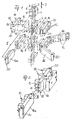
- Fig. 1 is a schematic view of the structure of a spray head according to the invention shown.
- a in the sense of arrows 2 movably guided part 1 of a Armes is arranged on its underside with several aligned to each other Distributor blocks 3 provided, all of identical design and are arranged in the direction of movement 2.
- the distributor blocks 3 are close to each other and arranged close to the terminal end of the arm 1.
- Passage channels 4 to 7 settle in each distribution block 3 below, and each of these channels branch off transversely Supply channels provided, each at the points 8, 9, 10 and 11 open at the sides of the manifolds 3. From there again the connection to spray nozzles 12 via connection plates 13 and Flange blocks 14, possibly also with the interposition of spacers 15. In this way it becomes possible, floor by floor, i.
- each in a horizontal plane of the manifolds 3 spray nozzles 12 to arrange in various ways to the spray block as possible good to the inner shape of the movable mold half and the solid mold half to adapt to a die casting machine. It is known that it is necessary after each casting this mold halves with release agent to spray or blow off with compressed air.
- the spray nozzles 12 are, as shown in particular in FIG. 2, each attached to spray bars 16 and 16a, the most to each other are identical.
- These spray bars 16 are in their interior with Passage channels 17, 18 and 19 are provided, of which the passageway 18, for example, to guide compressed air, the channel 17 for supplying a release agent and the channel 19 for feeding of control air, with the help of which equipped with the appropriate valves Spray nozzles 12 at certain times and opened can be closed again.
- These passageways 17 to 19 be, as shown in FIG. 2, either with the passageways a connected to adjacent spray bar 16a or, as shown in the Outside of the spray bars 16 is indicated by a closure piece 20 closed.
- Fig. 3 shows in which way the joining of the end faces the last 16 and 16a takes place. It can be seen that in alignment with the passageways 17 and 19 respectively in the end regions of Bar 16 and the bar 16a chambers 21 and 21a are provided, in both strips 16 and 16a each up to the adjacent Element adjacent end face 22 extend.
- the middle passageway 18 has in the region of the end face 22, which also has the separating surface forms between adjacent sub-elements, one each turn 23, which is each provided with a sealing ring 24, 24 a. These two Sealing rings therefore seal the passage 18 from when the Sub-elements 16 and 16a are assembled frontally.
- a connecting elements 25 used in the Embodiment in which also the chambers 21 are cylindrical, consist of cylindrical bolts, each with their end faces are provided in a recess arranged sealing ring 26, which abuts a mating surface of the chamber 21 when the elements are tightly joined together.
- the connecting element 25 has also two inclined surfaces 27 and 28, each to the ends of Connecting element 25 out from the axis of the connecting element from rise and in the embodiment part of a conical Hole in the periphery of the connecting element 25 are.
- the connecting elements 25 are, as can also be seen, each with a Passage channel 32 equipped, which is aligned with the passageway 17 or 19 runs and the same diameter as that Through passage 17 and 19 has.
- the connecting elements 25 therefore not only serve for mechanical juxtaposition of the Front ends of adjacent strips 16 or 16a, but they take over also the connection of the respective media channels in the to be coupled Share.
- Fig. 4 now shows that spray elements e.g. in mold with different Lengths in a simple manner by the invention Design can be coupled with each other. It's in the bottom Part strips 16 each aligned, the with spray nozzles 12 are provided. From the above it is clear that the media supply through these strips 16 through the channels 17, 18 and 19 takes place. At the outer end of these three aligned with each other arranged strips 16 is each a spray element 33 with only one Spray nozzle attached and running in this element Passageways are closed by a closure piece 20 outside. Also, this closure piece is in the manner explained in Fig. 3 way attached, as well as the element 33 connected to the bar 16 is.
Landscapes
- Engineering & Computer Science (AREA)
- Mechanical Engineering (AREA)
- Nozzles (AREA)
- Soil Working Implements (AREA)
- Organic Low-Molecular-Weight Compounds And Preparation Thereof (AREA)
- Catching Or Destruction (AREA)
Abstract
Description
- Fig. 1
- eine Explosionsdarstellung eines nach der Erfindung aufgebauten Sprühkopfes zum Besprühen einer Gießform,
- Fig. 2
- eine vergrößerte Darstellung des Details II der Fig. 1,
- Fig. 3
- eine vergrößerte Darstellung des Teilschnittes in Richtung der Ebene III in Fig. 2 und
- Fig. 4
- die Draufsicht in der Richtung der Bewegung des Sprühkopfes nach Fig. 1 auf eine gemäß der Erfindung aufgebaute Sprühkopfteilebene in einer in Fig. 1 nicht gezeigten Form.
Claims (9)
- Sprühkopf für ein Sprühwerkzeug, insbesondere zum Besprühen der Formhälften einer Druckgießmaschine, mit sprühmittelbeaufschlagten Sprühdüsen (12), die an Sprühplatten oder Sprühleisten angebracht sind, die aus Teilelementen (16, 16a) modulartig aufgebaut sind, dadurch gekennzeichnet, dass an den miteinander zu verbindenden Endbereichen der Teilelemente (16, 16a) Aufnahmekammern (21, 21a) für Verbindungselemente (25) vorgesehen sind, die mit Durchgangskanälen (17, 18, 19) für die zu versprühenden Medien in Verbindung stehen, dass die Verbindungselemente (25) jeweils in beide Kammern der untereinander zu verbindenden Enden hereinragen, mit einem Durchgangskanal (32) und mit Ausnehmungen mit mindestens einer schrägen Ebene (27, 28) versehen sind, an der Klemmmittel (30), die von außen betätigbar sind, angreifen und die Teilelemente (16, 16a) fest gegeneinander drücken.
- Sprühkopf nach Anspruch 1, dadurch gekennzeichnet, dass die Verbindungselemente (25) an beiden Stirnseiten mit Dichtringen (26) versehen sind.
- Sprühkopf nach Anspruch 1, dadurch gekennzeichnet, dass die Verbindungselemente (25) als zylindrischer Bolzen mit jeweils zwei Ausnehmungen ausgebildet sind, die mit jeweils zu einer Stirnseite hin ansteigenden schrägen Ebenen (27, 28) versehen sind.
- Sprühkopf nach Anspruch 1, dadurch gekennzeichnet, dass die Klemmmittel als Schrauben (30) ausgebildet sind, die mit einer Kegelspitze (29) mit den Ausnehmungen (27, 28) zusammenwirken.
- Sprühkopf nach Anspruch 1, dadurch gekennzeichnet, dass jeweils zwei Kammern (21) parallel zueinander an jedem Ende der Teilelemente (16, 16a) vorgesehen sind.
- Sprühkopf nach Anspruch 5, dadurch gekennzeichnet, dass die Kammern (21) achsgleich mit zwei der Durchgangskanäle (17, 19) verlaufen, insbesondere mit denen für Steuerluft und Trennmittel.
- Sprühkopf nach Anspruch 6, dadurch gekennzeichnet, dass zwischen den zwei Durchgangskanälen (17, 19), zu denen die Kammern (21) achsgleich verlaufen, ein dritter Durchgangskanal, insbesondere derjenige (18) für Trocknungsluft, verläuft.
- Sprühkopf nach Anspruch 1, dadurch gekennzeichnet, dass die Teilelemente (16, 16a) mit abgewinkelten Endbereichen versehen sind zum Anschluss weiterer Teilelemente.
- Sprühkopf nach Anspruch 8, dadurch gekennzeichnet, dass die Endbereiche von angesetzten Winkelstücken (35, 36) vorgebbarer Winkelstellung, insbesondere 45° bzw. 90°, gebildet sind.
Priority Applications (9)
| Application Number | Priority Date | Filing Date | Title |
|---|---|---|---|
| AT03009080T ATE318655T1 (de) | 2003-04-19 | 2003-04-19 | Sprühkopf für ein sprühwerkzeug |
| ES03009080T ES2258677T3 (es) | 2003-04-19 | 2003-04-19 | Cabeza de pulverizacion para una herramienta de pulverizacion. |
| EP03009080A EP1468747B1 (de) | 2003-04-19 | 2003-04-19 | Sprühkopf für ein Sprühwerkzeug |
| DE50302494T DE50302494D1 (de) | 2003-04-19 | 2003-04-19 | Sprühkopf für ein Sprühwerkzeug |
| US10/825,332 US7472841B2 (en) | 2003-04-19 | 2004-04-16 | Spray head for a spraying tool |
| PL367317A PL206688B1 (pl) | 2003-04-19 | 2004-04-16 | Głowica rozpylająca dla narzędzia rozpylającego |
| JP2004121468A JP4440695B2 (ja) | 2003-04-19 | 2004-04-16 | スプレー装置用のスプレーヘッド |
| CZ2004511A CZ2004511A3 (cs) | 2003-04-19 | 2004-04-19 | Postřikovací hlava pro postřikovací nástroj |
| HK05100056.6A HK1067575B (en) | 2005-01-05 | Sprayer head for a spray tool |
Applications Claiming Priority (1)
| Application Number | Priority Date | Filing Date | Title |
|---|---|---|---|
| EP03009080A EP1468747B1 (de) | 2003-04-19 | 2003-04-19 | Sprühkopf für ein Sprühwerkzeug |
Publications (2)
| Publication Number | Publication Date |
|---|---|
| EP1468747A1 true EP1468747A1 (de) | 2004-10-20 |
| EP1468747B1 EP1468747B1 (de) | 2006-03-01 |
Family
ID=32892920
Family Applications (1)
| Application Number | Title | Priority Date | Filing Date |
|---|---|---|---|
| EP03009080A Expired - Lifetime EP1468747B1 (de) | 2003-04-19 | 2003-04-19 | Sprühkopf für ein Sprühwerkzeug |
Country Status (8)
| Country | Link |
|---|---|
| US (1) | US7472841B2 (de) |
| EP (1) | EP1468747B1 (de) |
| JP (1) | JP4440695B2 (de) |
| AT (1) | ATE318655T1 (de) |
| CZ (1) | CZ2004511A3 (de) |
| DE (1) | DE50302494D1 (de) |
| ES (1) | ES2258677T3 (de) |
| PL (1) | PL206688B1 (de) |
Cited By (2)
| Publication number | Priority date | Publication date | Assignee | Title |
|---|---|---|---|---|
| DE102006062558A1 (de) | 2006-12-29 | 2008-07-03 | Bühler Druckguss AG | Verfahren zum Sprühen einer Giessform |
| WO2014035789A1 (en) * | 2012-08-28 | 2014-03-06 | The Gleason Works | Quick-change fluid supply apparatus for machining |
Families Citing this family (2)
| Publication number | Priority date | Publication date | Assignee | Title |
|---|---|---|---|---|
| US10525489B2 (en) * | 2013-03-15 | 2020-01-07 | Honda Motor Co., Ltd. | Automated sprayer assembly |
| CN108453234A (zh) * | 2018-06-25 | 2018-08-28 | 宁波科伟机器人科技有限公司 | 一种压铸生产用双臂机 |
Citations (3)
| Publication number | Priority date | Publication date | Assignee | Title |
|---|---|---|---|---|
| EP0125149A1 (de) * | 1983-05-10 | 1984-11-14 | Gerald Martin Welgemoed | Verbindungsstücke |
| US5916367A (en) * | 1993-10-23 | 1999-06-29 | Wotec Automationssysteme Gmbh | Spray head for a spraying tool |
| DE19941820C1 (de) * | 1999-09-02 | 2001-02-08 | Hansa Metallwerke Ag | Sanitärarmatur |
Family Cites Families (18)
| Publication number | Priority date | Publication date | Assignee | Title |
|---|---|---|---|---|
| US3341124A (en) * | 1965-06-21 | 1967-09-12 | Macmillan Bloedel And Powell R | Spraying method and apparatus |
| US4082324A (en) * | 1976-10-04 | 1978-04-04 | Obrecht Robert E | Connection arrangement for manifold blocks |
| FR2455923A1 (fr) * | 1979-05-11 | 1980-12-05 | Carrier | Dispositif de distribution de peintures, solvants, vernis ou analogues |
| US4605170A (en) * | 1985-08-23 | 1986-08-12 | Bayrisches Druckgusswerk Thurner Gmbh & Co. Kg | Apparatus for wetting mold surfaces with a liquid |
| JPS63123549A (ja) * | 1986-11-13 | 1988-05-27 | Hanano Shoji Kk | スプレ−装置 |
| US4760961A (en) * | 1987-02-13 | 1988-08-02 | The Snair Company | Modular sprayhead assembly |
| US4774109A (en) * | 1987-07-21 | 1988-09-27 | Nordson Corporation | Method and apparatus for applying narrow, closely spaced beads of viscous liquid to a substrate |
| US5518043A (en) * | 1995-01-09 | 1996-05-21 | Illinois Tool Works | Readily assembled and disassembled, modular, pneumatically powered strapping tool |
| JPH0949578A (ja) * | 1995-08-07 | 1997-02-18 | Smc Corp | 切換弁における管継手の取付け機構 |
| US5624106A (en) * | 1995-11-13 | 1997-04-29 | Weber; Gene | Gripping device |
| US5967418A (en) * | 1997-06-13 | 1999-10-19 | Macdonald; Robert W. | Spray bar for use with webs of different widths |
| JP4045366B2 (ja) * | 1997-08-11 | 2008-02-13 | Smc株式会社 | 流体圧機器用配管継手 |
| US6422428B1 (en) * | 1998-04-20 | 2002-07-23 | Nordson Corporation | Segmented applicator for hot melt adhesives or other thermoplastic materials |
| US6269823B1 (en) * | 1998-05-04 | 2001-08-07 | Eagle-Picher Industries, Inc. | Can washing apparatus with plastic risers |
| JP3471777B2 (ja) * | 2001-12-19 | 2003-12-02 | 花野商事株式会社 | スプレー装置 |
| DE10241199B4 (de) * | 2002-09-05 | 2009-01-02 | Hiwin Technologies Corp. | Linearführung mit pneumatischer Staubentfernung |
| US6814310B2 (en) * | 2002-11-26 | 2004-11-09 | Nordson Corporation | Metered liquid dispensing system |
| ATE318668T1 (de) * | 2003-04-19 | 2006-03-15 | Frech Oskar Gmbh & Co Kg | Sprühkopf für ein formsprühwerkzeug |
-
2003
- 2003-04-19 ES ES03009080T patent/ES2258677T3/es not_active Expired - Lifetime
- 2003-04-19 DE DE50302494T patent/DE50302494D1/de not_active Expired - Lifetime
- 2003-04-19 EP EP03009080A patent/EP1468747B1/de not_active Expired - Lifetime
- 2003-04-19 AT AT03009080T patent/ATE318655T1/de active
-
2004
- 2004-04-16 US US10/825,332 patent/US7472841B2/en not_active Expired - Fee Related
- 2004-04-16 JP JP2004121468A patent/JP4440695B2/ja not_active Expired - Fee Related
- 2004-04-16 PL PL367317A patent/PL206688B1/pl unknown
- 2004-04-19 CZ CZ2004511A patent/CZ2004511A3/cs unknown
Patent Citations (3)
| Publication number | Priority date | Publication date | Assignee | Title |
|---|---|---|---|---|
| EP0125149A1 (de) * | 1983-05-10 | 1984-11-14 | Gerald Martin Welgemoed | Verbindungsstücke |
| US5916367A (en) * | 1993-10-23 | 1999-06-29 | Wotec Automationssysteme Gmbh | Spray head for a spraying tool |
| DE19941820C1 (de) * | 1999-09-02 | 2001-02-08 | Hansa Metallwerke Ag | Sanitärarmatur |
Cited By (4)
| Publication number | Priority date | Publication date | Assignee | Title |
|---|---|---|---|---|
| DE102006062558A1 (de) | 2006-12-29 | 2008-07-03 | Bühler Druckguss AG | Verfahren zum Sprühen einer Giessform |
| WO2014035789A1 (en) * | 2012-08-28 | 2014-03-06 | The Gleason Works | Quick-change fluid supply apparatus for machining |
| CN104582897A (zh) * | 2012-08-28 | 2015-04-29 | 格里森工场 | 用于加工的快速更换流体供应装置 |
| US9796060B2 (en) | 2012-08-28 | 2017-10-24 | The Gleason Works | Quick-change fluid supply apparatus for machining |
Also Published As
| Publication number | Publication date |
|---|---|
| PL367317A1 (en) | 2004-11-02 |
| EP1468747B1 (de) | 2006-03-01 |
| JP4440695B2 (ja) | 2010-03-24 |
| DE50302494D1 (de) | 2006-04-27 |
| US20040217211A1 (en) | 2004-11-04 |
| HK1067575A1 (en) | 2005-04-15 |
| US7472841B2 (en) | 2009-01-06 |
| JP2004337848A (ja) | 2004-12-02 |
| ATE318655T1 (de) | 2006-03-15 |
| ES2258677T3 (es) | 2006-09-01 |
| PL206688B1 (pl) | 2010-09-30 |
| CZ2004511A3 (cs) | 2004-12-15 |
Similar Documents
| Publication | Publication Date | Title |
|---|---|---|
| DE102007028151B4 (de) | Ventilnadel-Betätigungseinheit für eine Heißläufervorrichtung | |
| DE3408607C2 (de) | ||
| DE1189264B (de) | Filteraustauschvorrichtung am Spritzkopf einer Kunststoff-Strangpresse oder Spritzmaschine | |
| DE10258170B3 (de) | Schmelzblaskopf | |
| EP0743162A1 (de) | Spritzkopf für eine Extrusionsanlage der Kautschuk oder Kunststoff verarbeitenden Industrie | |
| DE3930318C1 (de) | ||
| EP1468762B1 (de) | Sprühkopf für ein Formsprühwerkzeug | |
| DE69711797T2 (de) | Koextrusionsadapter | |
| EP1468747B1 (de) | Sprühkopf für ein Sprühwerkzeug | |
| DE2214646C3 (de) | Kunststoff-Spritzgießmaschine mit einer Formschließvorrichtung mit rechteckigem Grundkörper | |
| DE4016368A1 (de) | Spruehkopf einer spruehvorrichtung zum aufspruehen von fluessigkeiten, insbesondere trennmitteln | |
| EP0398389A2 (de) | Sprühkopf einer Sprühvorrichtung zum Aufsprühen von Flüssigkeiten, insbesondere Trennmitteln | |
| DE19956554A1 (de) | Heißkanal-Verteiler-System | |
| EP0898155A1 (de) | Zufuhrvorrichtung für ein rieselfähiges Aufgabegut in eine Dosiervorrichtung | |
| EP0849079A1 (de) | Trocknereinheit | |
| EP0992332A2 (de) | Heisskanalverschluss | |
| EP0374353A2 (de) | Etagenheisskanal-Bausatz mit nach entgegengesetzten Seiten gerichteten Nadelverschlussdüsen | |
| DE3820790C2 (de) | ||
| EP1468745A1 (de) | Sprühelement für einen Sprühkopf | |
| DE102010013441B4 (de) | Spritzgießdüsenanordnung und Spritzgießwerkzeug | |
| WO1995002494A1 (de) | Kaltkanalblock für die verarbeitung von elastomeren | |
| CH461080A (de) | Spritzgiessform für Kunststoffkettenglieder | |
| DE841666C (de) | Verbindungsbauteil | |
| DE2325949C3 (de) | Gewindekern für eine SpritzgieBvorr ich tu ng zum Herstellen eines mit einem Innen-Gewinde versehenen Formteils | |
| DE2526900A1 (de) | Spruehkopf |
Legal Events
| Date | Code | Title | Description |
|---|---|---|---|
| PUAI | Public reference made under article 153(3) epc to a published international application that has entered the european phase |
Free format text: ORIGINAL CODE: 0009012 |
|
| 17P | Request for examination filed |
Effective date: 20031009 |
|
| AK | Designated contracting states |
Kind code of ref document: A1 Designated state(s): AT BE BG CH CY CZ DE DK EE ES FI FR GB GR HU IE IT LI LU MC NL PT RO SE SI SK TR |
|
| AX | Request for extension of the european patent |
Extension state: AL LT LV MK |
|
| REG | Reference to a national code |
Ref country code: HK Ref legal event code: DE Ref document number: 1067575 Country of ref document: HK |
|
| AKX | Designation fees paid |
Designated state(s): AT BE BG CH CY CZ DE DK EE ES FI FR GB GR HU IE IT LI LU MC NL PT RO SE SI SK TR |
|
| GRAP | Despatch of communication of intention to grant a patent |
Free format text: ORIGINAL CODE: EPIDOSNIGR1 |
|
| GRAS | Grant fee paid |
Free format text: ORIGINAL CODE: EPIDOSNIGR3 |
|
| GRAA | (expected) grant |
Free format text: ORIGINAL CODE: 0009210 |
|
| AK | Designated contracting states |
Kind code of ref document: B1 Designated state(s): AT BE BG CH CY CZ DE DK EE ES FI FR GB GR HU IE IT LI LU MC NL PT RO SE SI SK TR |
|
| PG25 | Lapsed in a contracting state [announced via postgrant information from national office to epo] |
Ref country code: FI Free format text: LAPSE BECAUSE OF FAILURE TO SUBMIT A TRANSLATION OF THE DESCRIPTION OR TO PAY THE FEE WITHIN THE PRESCRIBED TIME-LIMIT Effective date: 20060301 Ref country code: NL Free format text: LAPSE BECAUSE OF FAILURE TO SUBMIT A TRANSLATION OF THE DESCRIPTION OR TO PAY THE FEE WITHIN THE PRESCRIBED TIME-LIMIT Effective date: 20060301 Ref country code: RO Free format text: LAPSE BECAUSE OF FAILURE TO SUBMIT A TRANSLATION OF THE DESCRIPTION OR TO PAY THE FEE WITHIN THE PRESCRIBED TIME-LIMIT Effective date: 20060301 Ref country code: IE Free format text: LAPSE BECAUSE OF FAILURE TO SUBMIT A TRANSLATION OF THE DESCRIPTION OR TO PAY THE FEE WITHIN THE PRESCRIBED TIME-LIMIT Effective date: 20060301 Ref country code: SK Free format text: LAPSE BECAUSE OF FAILURE TO SUBMIT A TRANSLATION OF THE DESCRIPTION OR TO PAY THE FEE WITHIN THE PRESCRIBED TIME-LIMIT Effective date: 20060301 Ref country code: SI Free format text: LAPSE BECAUSE OF FAILURE TO SUBMIT A TRANSLATION OF THE DESCRIPTION OR TO PAY THE FEE WITHIN THE PRESCRIBED TIME-LIMIT Effective date: 20060301 |
|
| REG | Reference to a national code |
Ref country code: GB Ref legal event code: FG4D Free format text: NOT ENGLISH |
|
| REG | Reference to a national code |
Ref country code: SE Ref legal event code: TRGR |
|
| REG | Reference to a national code |
Ref country code: CH Ref legal event code: EP |
|
| REG | Reference to a national code |
Ref country code: IE Ref legal event code: FG4D Free format text: LANGUAGE OF EP DOCUMENT: GERMAN |
|
| REF | Corresponds to: |
Ref document number: 50302494 Country of ref document: DE Date of ref document: 20060427 Kind code of ref document: P |
|
| PG25 | Lapsed in a contracting state [announced via postgrant information from national office to epo] |
Ref country code: BE Free format text: LAPSE BECAUSE OF NON-PAYMENT OF DUE FEES Effective date: 20060430 Ref country code: MC Free format text: LAPSE BECAUSE OF NON-PAYMENT OF DUE FEES Effective date: 20060430 |
|
| PG25 | Lapsed in a contracting state [announced via postgrant information from national office to epo] |
Ref country code: DK Free format text: LAPSE BECAUSE OF FAILURE TO SUBMIT A TRANSLATION OF THE DESCRIPTION OR TO PAY THE FEE WITHIN THE PRESCRIBED TIME-LIMIT Effective date: 20060601 Ref country code: BG Free format text: LAPSE BECAUSE OF FAILURE TO SUBMIT A TRANSLATION OF THE DESCRIPTION OR TO PAY THE FEE WITHIN THE PRESCRIBED TIME-LIMIT Effective date: 20060601 |
|
| GBT | Gb: translation of ep patent filed (gb section 77(6)(a)/1977) |
Effective date: 20060531 |
|
| REG | Reference to a national code |
Ref country code: CH Ref legal event code: NV Representative=s name: ZIMMERLI, WAGNER & PARTNER AG |
|
| PG25 | Lapsed in a contracting state [announced via postgrant information from national office to epo] |
Ref country code: PT Free format text: LAPSE BECAUSE OF FAILURE TO SUBMIT A TRANSLATION OF THE DESCRIPTION OR TO PAY THE FEE WITHIN THE PRESCRIBED TIME-LIMIT Effective date: 20060801 |
|
| REG | Reference to a national code |
Ref country code: HK Ref legal event code: GR Ref document number: 1067575 Country of ref document: HK |
|
| NLV1 | Nl: lapsed or annulled due to failure to fulfill the requirements of art. 29p and 29m of the patents act | ||
| REG | Reference to a national code |
Ref country code: ES Ref legal event code: FG2A Ref document number: 2258677 Country of ref document: ES Kind code of ref document: T3 |
|
| ET | Fr: translation filed | ||
| REG | Reference to a national code |
Ref country code: IE Ref legal event code: FD4D |
|
| PLBE | No opposition filed within time limit |
Free format text: ORIGINAL CODE: 0009261 |
|
| STAA | Information on the status of an ep patent application or granted ep patent |
Free format text: STATUS: NO OPPOSITION FILED WITHIN TIME LIMIT |
|
| 26N | No opposition filed |
Effective date: 20061204 |
|
| BERE | Be: lapsed |
Owner name: OSKAR FRECH G.M.B.H. + CO. KG Effective date: 20060430 |
|
| PG25 | Lapsed in a contracting state [announced via postgrant information from national office to epo] |
Ref country code: GR Free format text: LAPSE BECAUSE OF FAILURE TO SUBMIT A TRANSLATION OF THE DESCRIPTION OR TO PAY THE FEE WITHIN THE PRESCRIBED TIME-LIMIT Effective date: 20060602 |
|
| PG25 | Lapsed in a contracting state [announced via postgrant information from national office to epo] |
Ref country code: EE Free format text: LAPSE BECAUSE OF FAILURE TO SUBMIT A TRANSLATION OF THE DESCRIPTION OR TO PAY THE FEE WITHIN THE PRESCRIBED TIME-LIMIT Effective date: 20060301 |
|
| PG25 | Lapsed in a contracting state [announced via postgrant information from national office to epo] |
Ref country code: HU Free format text: LAPSE BECAUSE OF FAILURE TO SUBMIT A TRANSLATION OF THE DESCRIPTION OR TO PAY THE FEE WITHIN THE PRESCRIBED TIME-LIMIT Effective date: 20060902 Ref country code: TR Free format text: LAPSE BECAUSE OF FAILURE TO SUBMIT A TRANSLATION OF THE DESCRIPTION OR TO PAY THE FEE WITHIN THE PRESCRIBED TIME-LIMIT Effective date: 20060301 Ref country code: LU Free format text: LAPSE BECAUSE OF NON-PAYMENT OF DUE FEES Effective date: 20060419 |
|
| PG25 | Lapsed in a contracting state [announced via postgrant information from national office to epo] |
Ref country code: CY Free format text: LAPSE BECAUSE OF FAILURE TO SUBMIT A TRANSLATION OF THE DESCRIPTION OR TO PAY THE FEE WITHIN THE PRESCRIBED TIME-LIMIT Effective date: 20060301 |
|
| REG | Reference to a national code |
Ref country code: CH Ref legal event code: PFA Owner name: OSKAR FRECH GMBH + CO. KG Free format text: OSKAR FRECH GMBH + CO. KG#SCHORNDORFER STRASSE 32#73614 SCHORNDORF (DE) -TRANSFER TO- OSKAR FRECH GMBH + CO. KG#SCHORNDORFER STRASSE 32#73614 SCHORNDORF (DE) |
|
| REG | Reference to a national code |
Ref country code: CH Ref legal event code: NV Representative=s name: WAGNER PATENT AG, CH |
|
| REG | Reference to a national code |
Ref country code: FR Ref legal event code: PLFP Year of fee payment: 14 |
|
| REG | Reference to a national code |
Ref country code: FR Ref legal event code: PLFP Year of fee payment: 15 |
|
| REG | Reference to a national code |
Ref country code: DE Ref legal event code: R079 Ref document number: 50302494 Country of ref document: DE Free format text: PREVIOUS MAIN CLASS: B05B0015060000 Ipc: B05B0015600000 |
|
| REG | Reference to a national code |
Ref country code: FR Ref legal event code: PLFP Year of fee payment: 16 |
|
| PGFP | Annual fee paid to national office [announced via postgrant information from national office to epo] |
Ref country code: IT Payment date: 20190419 Year of fee payment: 17 Ref country code: DE Payment date: 20190418 Year of fee payment: 17 Ref country code: CZ Payment date: 20190411 Year of fee payment: 17 Ref country code: ES Payment date: 20190520 Year of fee payment: 17 |
|
| PGFP | Annual fee paid to national office [announced via postgrant information from national office to epo] |
Ref country code: SE Payment date: 20190425 Year of fee payment: 17 Ref country code: FR Payment date: 20190423 Year of fee payment: 17 |
|
| PGFP | Annual fee paid to national office [announced via postgrant information from national office to epo] |
Ref country code: CH Payment date: 20190424 Year of fee payment: 17 |
|
| PGFP | Annual fee paid to national office [announced via postgrant information from national office to epo] |
Ref country code: AT Payment date: 20190416 Year of fee payment: 17 Ref country code: GB Payment date: 20190424 Year of fee payment: 17 |
|
| REG | Reference to a national code |
Ref country code: DE Ref legal event code: R119 Ref document number: 50302494 Country of ref document: DE |
|
| REG | Reference to a national code |
Ref country code: CH Ref legal event code: PL |
|
| REG | Reference to a national code |
Ref country code: AT Ref legal event code: MM01 Ref document number: 318655 Country of ref document: AT Kind code of ref document: T Effective date: 20200419 |
|
| PG25 | Lapsed in a contracting state [announced via postgrant information from national office to epo] |
Ref country code: FR Free format text: LAPSE BECAUSE OF NON-PAYMENT OF DUE FEES Effective date: 20200430 Ref country code: SE Free format text: LAPSE BECAUSE OF NON-PAYMENT OF DUE FEES Effective date: 20200420 Ref country code: LI Free format text: LAPSE BECAUSE OF NON-PAYMENT OF DUE FEES Effective date: 20200430 Ref country code: DE Free format text: LAPSE BECAUSE OF NON-PAYMENT OF DUE FEES Effective date: 20201103 Ref country code: CH Free format text: LAPSE BECAUSE OF NON-PAYMENT OF DUE FEES Effective date: 20200430 Ref country code: AT Free format text: LAPSE BECAUSE OF NON-PAYMENT OF DUE FEES Effective date: 20200419 Ref country code: CZ Free format text: LAPSE BECAUSE OF NON-PAYMENT OF DUE FEES Effective date: 20200419 |
|
| GBPC | Gb: european patent ceased through non-payment of renewal fee |
Effective date: 20200419 |
|
| PG25 | Lapsed in a contracting state [announced via postgrant information from national office to epo] |
Ref country code: GB Free format text: LAPSE BECAUSE OF NON-PAYMENT OF DUE FEES Effective date: 20200419 |
|
| REG | Reference to a national code |
Ref country code: ES Ref legal event code: FD2A Effective date: 20210902 |
|
| PG25 | Lapsed in a contracting state [announced via postgrant information from national office to epo] |
Ref country code: IT Free format text: LAPSE BECAUSE OF NON-PAYMENT OF DUE FEES Effective date: 20200419 |
|
| PG25 | Lapsed in a contracting state [announced via postgrant information from national office to epo] |
Ref country code: ES Free format text: LAPSE BECAUSE OF NON-PAYMENT OF DUE FEES Effective date: 20200420 |