EP1468598A2 - Ramasseuse-hacheuse avec cabine du conducteur apte à être positionnée - Google Patents
Ramasseuse-hacheuse avec cabine du conducteur apte à être positionnée Download PDFInfo
- Publication number
- EP1468598A2 EP1468598A2 EP04008212A EP04008212A EP1468598A2 EP 1468598 A2 EP1468598 A2 EP 1468598A2 EP 04008212 A EP04008212 A EP 04008212A EP 04008212 A EP04008212 A EP 04008212A EP 1468598 A2 EP1468598 A2 EP 1468598A2
- Authority
- EP
- European Patent Office
- Prior art keywords
- forage harvester
- self
- harvester according
- propelled forage
- chute
- Prior art date
- Legal status (The legal status is an assumption and is not a legal conclusion. Google has not performed a legal analysis and makes no representation as to the accuracy of the status listed.)
- Granted
Links
Images


Classifications
-
- A—HUMAN NECESSITIES
- A01—AGRICULTURE; FORESTRY; ANIMAL HUSBANDRY; HUNTING; TRAPPING; FISHING
- A01D—HARVESTING; MOWING
- A01D41/00—Combines, i.e. harvesters or mowers combined with threshing devices
- A01D41/12—Details of combines
- A01D41/14—Mowing tables
- A01D41/144—Foldable headers
-
- A—HUMAN NECESSITIES
- A01—AGRICULTURE; FORESTRY; ANIMAL HUSBANDRY; HUNTING; TRAPPING; FISHING
- A01D—HARVESTING; MOWING
- A01D43/00—Mowers combined with apparatus performing additional operations while mowing
- A01D43/08—Mowers combined with apparatus performing additional operations while mowing with means for cutting up the mown crop, e.g. forage harvesters
- A01D43/086—Mowers combined with apparatus performing additional operations while mowing with means for cutting up the mown crop, e.g. forage harvesters and means for collecting, gathering or loading mown material
- A01D43/087—Mowers combined with apparatus performing additional operations while mowing with means for cutting up the mown crop, e.g. forage harvesters and means for collecting, gathering or loading mown material with controllable discharge spout
-
- A—HUMAN NECESSITIES
- A01—AGRICULTURE; FORESTRY; ANIMAL HUSBANDRY; HUNTING; TRAPPING; FISHING
- A01D—HARVESTING; MOWING
- A01D67/00—Undercarriages or frames specially adapted for harvesters or mowers; Mechanisms for adjusting the frame; Platforms
Definitions
- the invention relates to a self-propelled forage harvester according to the preamble of Claims 1 and / or 18.
- Self-driving vehicles with positionable driver's cab are from the DE-OS 2 046 552 known.
- this In vehicles the driver's cab can be rotated on one arm and swiveled horizontally attached around a hinge axis and can be adjusted in at least two positions become.
- the chassis of the vehicles are equipped with devices for coupling or equipped to accommodate work organs. Before taking one The driver's cab becomes the working space from the installation space required for the Work organ pivoted into a position that the driver's cabin to the chassis aligns and or an optimal view of the driver in the direction of travel or on the Working organ offers.
- a disadvantage of such embodiments is that the Driver's cabin not around the coupled work organs in one opposite position is changeable.
- Modern forage harvesters drive up to 40 km / h on the road. With coupled tool is the load on the front axle compared to the load the rear axle is very high, the focus of the forage harvester is very close to that Front axle and is also very far from the arrangement of the drive Ground. With this weight distribution, the vehicles tend to accelerate or brakes easy to swing or rock. The on steering locks and Road bumps sensitive vehicles are at high Difficult to control speeds. The uneven load distribution is balanced by ballast on the support frame in the area of the rear axle is attached. The disadvantage here is that the total weight of the forage harvester is increased and at the same time the payload is reduced.
- the invention is based, the driving characteristics and thus the task Driving comfort of the forage harvester to different operating situations on the Adaptable on the road and in the field with and without the attached attachment and improve it.
- the position is preferably changed by moving and / or swivel the cabin.
- the cabin is in any position with the chassis connected.
- the Swivel device with a variable-length swivel arm, so that the cabin can be moved in relation to the axle units.
- the swivel device has a Axis of rotation, which is arranged outside the chute, so that the Part of the swivel device can rotate around the chute without the Touch the chute.
- the driver can Driver's cab in the chopper operating position and in the road operating position Reach comfortably and safely.
- the spout is one the horizontal axis can be swiveled so that it is lowered in road operation can be and the chopped material different for overloading in the chop operation deflected high and wide.
- Constructively simple and preventing collisions is a variant in which the Driver's cab and the discharge spout only in the same direction in different positions can be movable around the chute.
- the movement of the Spout is limited by stops. This ensures that on the one hand, a flexibly designed overloading area can be covered and on the other hand, collisions with other assemblies can be avoided.
- the driver's cab is advantageously approximately in the middle in the road operating position arranged between the axle units. In this position they are on the driver vibrations reduced.
- a further advantageous embodiment of the invention results when the Driver's cab is arranged to lift the chute.
- the driver offers in this position the best view of the discharge spout.
- the driver's cab can be slidably attached to a sliding guide and at the same time be pivoted about a vertical axis. In this It is possible that the cabin is completely around the chute can move.
- the axis of rotation of the Ejector and the center of motion of the sliding guide coaxial.
- the spout and the cabin advantageously move around common center.
- This arrangement has a positive effect on the Driving comfort, as they have an advantageous weight distribution on the forage harvester conditionally.
- the focus of the drive unit is close to the others Axis unit so that the forage harvester can tip over even on a slope.
- the functional assembly is one Feed chute and the chute are formed.
- the chute takes several working bodies.
- the working bodies can do this execution according to the invention the chopper drum, the corn cracker and the Be an accelerator.
- the feed shaft takes several pre-press rollers.
- the drive unit consists of a Engine, gearbox and radiator.
- Attachment device In order to move the center of gravity of the attachment closer to the support frame, this is Attachment device in a transport position at least partially in the area of the layer the cab can be swiveled into the chopper operating position.
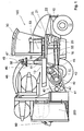
- the forage harvester 100 shown in FIG. 1 shows a chassis 10 on which one Driver cabin 30 is attached. In addition to the cabin 30, this is on the chassis 10 Upper end of an ascending chute 46 arranged from a chopper drum 43 within the chassis 10 to above the chassis 10 extends.
- the driver's cab 30 is approximately in a road operating position 31 in the middle between a first axle unit 12 and the chute 46, the view the driver is directed in the direction of the first axis unit 12.
- the Driver cabin 30 is mounted on a swivel device 50 which is about a vertical axis of rotation 51 is horizontally pivotable.
- the swivel device 50 is as variable length straight swivel arm 55 formed on the outer End of the driver's cab 30 is mounted rotatably about the vertical axis of rotation 53.
- the axis of rotation 51 and the swivel device 50 lie in front of the chute, so that when the driver's cab 30 is pivoted through 180 ° around the chute 46 around neither the driver's cab 30 nor the swivel device 50 den Touch chute 46 or fall below a safety distance.
- slewing ring 47 Around a vertical Axis of rotation 49 flanged spout 48, which is additionally one horizontal axis 58 is adjustable in height.
- the spout 48 is in one Road operating position 60 is set in the direction of a further axis unit 11.
- the chassis 10 of the forage harvester is supported by the two axle units 11, 12 carried.
- the first axle unit 12 has smaller wheels than the other Axis unit 11 equipped.
- the chassis supports in the vicinity of the first axle unit 12 10 shows a drive unit 20.
- FIG. 1 shows the drive unit 20 in partial section consists of a motor 21, a gear 22 and a cooling system 23. Der Most of the load of the drive unit 20 rests on the first axle unit 12, the center of gravity of the drive unit 20 is determined by the arrangement of the motor 21 and the gear 22 is located approximately at the level of the first axle unit 12.
- a functional assembly 40 which consists of a feed chute 41 in which a plurality of pre-press rollers 42 are rotatably mounted, and the one downstream of this feed slot 41 includes approximately vertically extending chute 46 in the successive a chopper drum 43, a downstream corn cracker (not shown) and a post-accelerator 45 are arranged. It is within the scope of the invention that 46 other organs not described can be assigned to the chute.
- the feed chute 41 is a known position and one at the following location Assigned attachment 200 explained in more detail. Most of the burdens of the Functional assembly 40 and the front attachment 200 rests on the second Axis unit 11.
- the front attachment 200 is folded into a transport position 220 and thereby partially arranged above the support frame 10.
- FIG. 2 shows a schematic top view of the forage harvester 100 according to the invention with a row-independent attachment 200.
- the driver's cab 30 is in a chopper operating position 32 above the axle unit 11 and the driver's gaze is directed towards the attachment 200 when steering.
- the Spout 43 is in a chopper operating position 65 transverse to the longitudinal axis of the Put forage harvester 100, from which he countered when chopping about the axis of rotation 49 can be turned clockwise by 180 °.
- the swivel device 50 and the Pivot 51 are arranged next to the chute 46.
- the driver's cab 30 and the discharge chute 48 change back moved in the same direction around the chute 46. Stops prevent the driver's cabin 30 and the spout 48 collide.
- the movement of the The driver's cabin 30 and the discharge spout 48 are changing position coupled to each other. The movements are, for example, via sensors electronically monitors the determined data to an evaluation unit pass on. The evaluation unit evaluates the data and outputs e.g. through software supports the movements for the spout 48 and the cab 30 in front.
- the driver's cabin 30 is on an ascent 16 in the vicinity of the axle unit 11 the right side of the forage harvester 100.
- the unfolded attachment 200 the front of the chassis 10 in front the feed slot 41 is mounted, is in a working position 210.
- Das Front attachment 200 extends beyond the width of the forage harvester 100, it is in this Position arranged below the support level 13.
- the focus of the parallel to Axle unit 11 lying unfolded header 200 is in front of Axle unit 11 outside the chassis 10.
- the corn standing in the field is cut by the header 200 and used for Feed chute 41 transported, the corn is from the functional module 40th processed and the resulting product leaves the functional module 40 the chute 46.
- the one directly adjoining the chute 46 Spout 48 directs the goods in the desired direction for overloading.
- the forage harvester 100 of FIG. 2 is preferably harvested in one Chopping direction HF on the field, of course it can Forage harvester 100 for maneuvering backwards, in the opposite direction drive.
- FIG 3 shows a schematic top view of the forage harvester 100 according to the invention with a row-independent attachment 200 in a folded up position Transport position 220.
- the folded-up attachment 200 is narrower than that width of the forage harvester 100.
- the driver's cab 30 is in the road operating position shown via a second ascent 17 on the right, accessible between the axle units 11, 12 is attached to the support frame 10.
- the forage harvester 100 of FIG. 3 is preferably in a road direction SF driven on the road, of course the forage harvester 100 can Maneuver backwards, drive in the opposite direction.
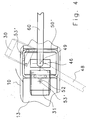
- FIG. 4 shows a second embodiment of the swivel device 50 '.
- the articulated arm 52 is in the sliding guide at the inner end 50 'slidably attached.
- the Driver cabin 30 is rotatably mounted about a vertical axis of rotation 53 '.
- the cabin 50 is pivoted about a center of motion 51 'which is aligned with the axis of rotation 49 of the Spout is coaxial.
- This embodiment enables complete partially rotatory and partially translatory circulation of the driver's cab 30 um around the chute 46.
Applications Claiming Priority (2)
| Application Number | Priority Date | Filing Date | Title |
|---|---|---|---|
| DE10317816 | 2003-04-16 | ||
| DE10317816A DE10317816A1 (de) | 2003-04-16 | 2003-04-16 | Feldhäcksler mit positionierbarer Fahrerkabine |
Publications (3)
| Publication Number | Publication Date |
|---|---|
| EP1468598A2 true EP1468598A2 (fr) | 2004-10-20 |
| EP1468598A3 EP1468598A3 (fr) | 2009-08-26 |
| EP1468598B1 EP1468598B1 (fr) | 2012-12-19 |
Family
ID=32892413
Family Applications (1)
| Application Number | Title | Priority Date | Filing Date |
|---|---|---|---|
| EP04008212A Expired - Lifetime EP1468598B1 (fr) | 2003-04-16 | 2004-04-05 | Ramasseuse-hacheuse avec cabine du conducteur apte à être positionnée |
Country Status (3)
| Country | Link |
|---|---|
| US (2) | US7003938B2 (fr) |
| EP (1) | EP1468598B1 (fr) |
| DE (1) | DE10317816A1 (fr) |
Cited By (8)
| Publication number | Priority date | Publication date | Assignee | Title |
|---|---|---|---|---|
| FR2881609A1 (fr) * | 2005-02-09 | 2006-08-11 | Kuhn Sa Sa | Engin agricole pour la coupe de produits comportant un vehicule porteur et des unites de travail |
| EP1779717A1 (fr) * | 2005-10-28 | 2007-05-02 | Claas Saulgau Gmbh | Amélioration de la visibilité dans des machines de travail automotrices |
| EP1894462A1 (fr) | 2006-08-28 | 2008-03-05 | CLAAS Selbstfahrende Erntemaschinen GmbH | Convoyeur agricole |
| EP1894463A1 (fr) | 2006-08-28 | 2008-03-05 | CLAAS Selbstfahrende Erntemaschinen GmbH | Moissonneuse agricole dotée d'un dispositif de surcharge |
| DE102007035745A1 (de) * | 2007-07-31 | 2009-02-05 | Maschinenfabrik Kemper Gmbh & Co. Kg | Erntevorsatz mit seitlicher Abdeckung |
| EP1671837A3 (fr) * | 2004-11-08 | 2009-11-25 | CLAAS Selbstfahrende Erntemaschinen GmbH | Siège de conducteur pivotant dans une cabine de conduit d'un véhicule agricole |
| CN105532160A (zh) * | 2016-02-02 | 2016-05-04 | 张东军 | 自走式高效元胡精选收获机 |
| AT16978U3 (de) * | 2020-09-08 | 2021-10-15 | Manfred Saller | Häcksler |
Families Citing this family (19)
| Publication number | Priority date | Publication date | Assignee | Title |
|---|---|---|---|---|
| FR2837347B1 (fr) * | 2002-03-21 | 2004-07-30 | Kuhn Sa | Faucheuse agricole comportant un vehicule porteur et plusieurs unites de travail |
| DE102004057048A1 (de) * | 2004-11-25 | 2006-06-08 | Claas Selbstfahrende Erntemaschinen Gmbh | Mähdrescher |
| CN101137636A (zh) | 2005-01-14 | 2008-03-05 | 先灵公司 | Himbacine类似物的外型选择性合成 |
| EP1716742A1 (fr) * | 2005-04-27 | 2006-11-02 | Claas Saulgau Gmbh | Appareil pour la récolte |
| FR2885484B1 (fr) * | 2005-05-10 | 2007-06-15 | Kuhn Sa Sa | Engin agricole comportant un vehicule moteur et plusieurs unites de travail destinees a couper des produits vegetaux |
| FR2895211B1 (fr) * | 2005-12-22 | 2009-11-20 | Kuhn Sa | Engin agricole comportant un attelage perfectionne |
| EP1869968B1 (fr) * | 2006-06-22 | 2009-11-18 | Maasland N.V. | Dispositif de traitement des récoltes comportant un dispositif de ramassage/coupe |
| TWI367112B (en) * | 2006-06-30 | 2012-07-01 | Schering Corp | Immediate-release tablet formulations of a thrombin receptor antagonist |
| CA2673228A1 (fr) * | 2006-12-22 | 2008-07-03 | Schering Corporation | Promoteurs de desintegration dans des formulations de forme solide obtenues par un procede de granulation par voie humide |
| US7806757B2 (en) * | 2008-07-16 | 2010-10-05 | Deere & Company | Dual sided belted unloader |
| DE102008049130A1 (de) * | 2008-09-26 | 2010-04-01 | Claas Selbstfahrende Erntemaschinen Gmbh | Landwirtschaftliche Erntemaschine |
| AU2010259003A1 (en) | 2009-06-08 | 2011-11-10 | Merck Sharp & Dohme Corp. | A thrombin receptor antagonist and clopidogrel fixed dose tablet |
| US8197312B2 (en) * | 2009-12-04 | 2012-06-12 | Cnh America Llc | Extension for an agricultural combine unloader tube |
| US20130019580A1 (en) * | 2011-07-20 | 2013-01-24 | Anderson Noel W | Bidirectional harvesting system |
| WO2014046685A1 (fr) * | 2012-09-24 | 2014-03-27 | Deere & Company | Système de récolte bidirectionnel |
| USD797813S1 (en) * | 2016-02-22 | 2017-09-19 | Claas Kgaa Mbh | Harvester |
| US10785913B2 (en) * | 2018-04-30 | 2020-09-29 | Orchard-Rite Ltd., Inc. | Two-piece harvester having a shaker and a receiver for harvesting tree fruits or nuts |
| NL2021519B1 (nl) * | 2018-08-30 | 2020-04-24 | Ploeger Oxbo Europe B V | Zelfrijdende landbouwmachine, bijvoorbeeld een zelfrijdende bandhark |
| DE102019212647A1 (de) * | 2019-08-23 | 2021-02-25 | Deere & Company | Feldhäcksler mit Auswurfkrümmer und positionsverstellbarer Kabine |
Citations (1)
| Publication number | Priority date | Publication date | Assignee | Title |
|---|---|---|---|---|
| DE2046552A1 (de) | 1969-09-23 | 1971-04-01 | C van der LeIy N V , Maasland (Niederlande) | Schlepper mit verschiebbarem Fahrer sitz |
Family Cites Families (29)
| Publication number | Priority date | Publication date | Assignee | Title |
|---|---|---|---|---|
| US3182605A (en) * | 1963-10-07 | 1965-05-11 | Lawrence J Brasher | Vehicle control |
| NL6401807A (fr) * | 1964-02-26 | 1965-08-27 | ||
| NL6402194A (fr) * | 1964-03-05 | 1965-09-06 | ||
| US3352093A (en) * | 1965-06-08 | 1967-11-14 | Sperry Rand Corp | Forage harvester |
| NL158447B (nl) * | 1968-10-07 | 1978-11-15 | Lely Nv C Van Der | Trekker voor landbouwdoeleinden met een laadvlak. |
| CH519291A (de) * | 1968-10-07 | 1972-02-29 | Lely Nv C Van Der | Als Schlepper verwendbare selbstfahrende landwirtschaftliche Maschine |
| US3825138A (en) * | 1972-10-24 | 1974-07-23 | Mathews B | Unloader for the grain bin of a combine |
| GB1518798A (en) * | 1974-10-05 | 1978-07-26 | Coles Cranes Ltd | Rough terrain cranes (swingable cb) |
| FR2340850A1 (fr) * | 1976-02-10 | 1977-09-09 | Bidon Jacques | Vehicule tracteur, notamment a usage agricole |
| DE3024650A1 (de) * | 1980-06-30 | 1982-02-25 | Claas Ohg, 4834 Harsewinkel | Selbstfahrendes landwirtschaftliches mehrzweckfahrzeug mit versetzbarer fahrerkabine |
| DE3024664A1 (de) * | 1980-06-30 | 1982-02-04 | Claas Ohg, 4834 Harsewinkel | Landwirtschaftliches mehrzweckfahrzeug |
| US4355690A (en) * | 1980-12-18 | 1982-10-26 | Deere & Company | Stack folding outrigger system |
| SE425648B (sv) * | 1981-03-13 | 1982-10-25 | Kockums Ind Ab | Hjulburet arbetsfordon med lastkran |
| US4409780A (en) * | 1982-03-11 | 1983-10-18 | Kansas State University Research Foundation | Folding header assembly |
| DE3234657A1 (de) * | 1982-09-18 | 1984-03-22 | Claas Ohg, 4834 Harsewinkel | Feldhaecksler |
| NL8203654A (nl) * | 1982-09-21 | 1984-04-16 | Patent Concern Nv | Trekker, in het bijzonder een trekker voor landbouwdoeleinden. |
| DE3346309A1 (de) * | 1983-01-04 | 1984-07-12 | Karl-Heinz 6711 Heuchelheim Obermaier | Motorfahrzeug mit lageveraenderbarer fahrerkabine |
| US4903470A (en) * | 1987-09-14 | 1990-02-27 | Claas Ohg | Self-propelling harvester thresher with two-part cutting mechanism |
| DE3911524A1 (de) * | 1989-04-08 | 1990-10-11 | Claas Ohg | Landwirtschaftliches traegerfahrzeug |
| DE19523255A1 (de) * | 1995-06-27 | 1997-01-02 | Claas Saulgau Gmbh | Erntevorsatz an landwirtschaftlichen Arbeitsmaschinen zum Aufnehmen und Weiterführen von Halmfrüchten, beispielsweise Maispflanzen |
| DE19524752B4 (de) * | 1995-07-07 | 2004-08-12 | Claas Kgaa Mbh | Vorrichtung und Verfahren zur Durchsatzmessung in einer landwirtschaftlichen Erntemaschine |
| US6032444A (en) * | 1997-06-04 | 2000-03-07 | Hay & Forage Industries | Non-row-sensitive forage harvester |
| CA2240869C (fr) * | 1998-06-17 | 2005-08-23 | Bourgault Industries Ltd. | Entrainement de chariots a cereales |
| DE19903471C1 (de) * | 1999-01-29 | 2000-06-08 | Deere & Co | Erntemaschine mit Durchsatzmeßvorrichtung |
| DE19918551B4 (de) * | 1999-04-23 | 2015-04-02 | Deere & Company | Erntemaschine |
| DE19958280A1 (de) * | 1999-12-03 | 2001-06-13 | Peter Gallersdoerfer | Selbstfahrende landwirtschaftliche Arbeitsmaschine |
| DE10021664B4 (de) * | 2000-05-04 | 2004-05-06 | Maschinenfabrik Bernard Krone Gmbh | Erntemaschine, insbesondere selbstfahrender Feldhäcksler |
| DE20007994U1 (de) * | 2000-05-04 | 2001-09-13 | Krone Bernhard Gmbh Maschf | Selbstfahrende Erntemaschine, insbesondere Feldhäcksler |
| DE10142978A1 (de) * | 2001-09-01 | 2003-03-20 | Kemper Gmbh Maschf | Erntevorsatz |
-
2003
- 2003-04-16 DE DE10317816A patent/DE10317816A1/de not_active Withdrawn
-
2004
- 2004-04-05 EP EP04008212A patent/EP1468598B1/fr not_active Expired - Lifetime
- 2004-04-05 US US10/818,484 patent/US7003938B2/en not_active Expired - Fee Related
-
2005
- 2005-05-10 US US11/125,633 patent/US7222480B2/en not_active Expired - Fee Related
Patent Citations (1)
| Publication number | Priority date | Publication date | Assignee | Title |
|---|---|---|---|---|
| DE2046552A1 (de) | 1969-09-23 | 1971-04-01 | C van der LeIy N V , Maasland (Niederlande) | Schlepper mit verschiebbarem Fahrer sitz |
Cited By (11)
| Publication number | Priority date | Publication date | Assignee | Title |
|---|---|---|---|---|
| EP1671837A3 (fr) * | 2004-11-08 | 2009-11-25 | CLAAS Selbstfahrende Erntemaschinen GmbH | Siège de conducteur pivotant dans une cabine de conduit d'un véhicule agricole |
| FR2881609A1 (fr) * | 2005-02-09 | 2006-08-11 | Kuhn Sa Sa | Engin agricole pour la coupe de produits comportant un vehicule porteur et des unites de travail |
| EP1690446A1 (fr) * | 2005-02-09 | 2006-08-16 | Kuhn S.A. | Engin agricole pour la coupe de produits |
| US7543433B2 (en) | 2005-02-09 | 2009-06-09 | Kuhn S.A. | Agricultural machine for cutting products |
| CN100592867C (zh) * | 2005-02-09 | 2010-03-03 | 库恩股份有限公司 | 用于切割产品的农业机器 |
| EP1779717A1 (fr) * | 2005-10-28 | 2007-05-02 | Claas Saulgau Gmbh | Amélioration de la visibilité dans des machines de travail automotrices |
| EP1894462A1 (fr) | 2006-08-28 | 2008-03-05 | CLAAS Selbstfahrende Erntemaschinen GmbH | Convoyeur agricole |
| EP1894463A1 (fr) | 2006-08-28 | 2008-03-05 | CLAAS Selbstfahrende Erntemaschinen GmbH | Moissonneuse agricole dotée d'un dispositif de surcharge |
| DE102007035745A1 (de) * | 2007-07-31 | 2009-02-05 | Maschinenfabrik Kemper Gmbh & Co. Kg | Erntevorsatz mit seitlicher Abdeckung |
| CN105532160A (zh) * | 2016-02-02 | 2016-05-04 | 张东军 | 自走式高效元胡精选收获机 |
| AT16978U3 (de) * | 2020-09-08 | 2021-10-15 | Manfred Saller | Häcksler |
Also Published As
| Publication number | Publication date |
|---|---|
| US20050210850A1 (en) | 2005-09-29 |
| US7222480B2 (en) | 2007-05-29 |
| EP1468598B1 (fr) | 2012-12-19 |
| US7003938B2 (en) | 2006-02-28 |
| DE10317816A1 (de) | 2004-11-04 |
| US20040216437A1 (en) | 2004-11-04 |
| EP1468598A3 (fr) | 2009-08-26 |
Similar Documents
| Publication | Publication Date | Title |
|---|---|---|
| EP1468598A2 (fr) | Ramasseuse-hacheuse avec cabine du conducteur apte à être positionnée | |
| DE1949978A1 (de) | Universalschlepper | |
| EP1444881A2 (fr) | Système d'entraínement pour le système de récolte d'une machine de récolte | |
| EP0827684A2 (fr) | Moissonneuse agricole autopropulsée | |
| EP1440617A1 (fr) | Système d'entrainement pour une tête de récolte d'une machine de récolte | |
| DE1950497B2 (de) | Schlepper mit einer Ladefläche für Nutzlasten | |
| DE3702221A1 (de) | Maehmaschine | |
| EP1618777B1 (fr) | Dispositif de décharge d'une récolteuse agricole | |
| DE2252105A1 (de) | Maehdrescher | |
| EP1048195A1 (fr) | Dispositif de pivotement pour roues de support | |
| DE4340384B4 (de) | Heuwerbungsmaschine | |
| EP1894462B1 (fr) | Convoyeur agricole | |
| EP1894463B1 (fr) | Moissonneuse agricole dotée d'un dispositif de surcharge | |
| DE19802199A1 (de) | Entleervorrichtung für einen Behälter | |
| EP1932414B1 (fr) | Faucheuse destinée à être placée au front d'un véhicule agricole | |
| DE1966495A1 (de) | Schlepper | |
| EP1093710B1 (fr) | Tracteur à dispositif faucheur frontal | |
| EP0736244A2 (fr) | Machine de récolte munie de moyens de compensation pour le travail sur une pente | |
| DE3713474A1 (de) | Heuwerbungsmaschine | |
| EP0331070A1 (fr) | Véhicule agricole polyvalent | |
| DE2018070A1 (de) | Mehrzweck - Motorfahrzeug, insbesondere Geräteträger | |
| DE3205748C2 (de) | Selbstfahrendes landwirtschaftliches Mehrzweckfahrzeug | |
| EP1145620B1 (fr) | Machine de fenaison | |
| EP0698338B1 (fr) | Machine de récolte munie de moyens de compensation pour le travail sur une pente | |
| DE60315094T2 (de) | Hubvorrichtung für ein Flurförderzeug |
Legal Events
| Date | Code | Title | Description |
|---|---|---|---|
| PUAI | Public reference made under article 153(3) epc to a published international application that has entered the european phase |
Free format text: ORIGINAL CODE: 0009012 |
|
| AK | Designated contracting states |
Kind code of ref document: A2 Designated state(s): AT BE BG CH CY CZ DE DK EE ES FI FR GB GR HU IE IT LI LU MC NL PL PT RO SE SI SK TR |
|
| AX | Request for extension of the european patent |
Extension state: AL HR LT LV MK |
|
| PUAL | Search report despatched |
Free format text: ORIGINAL CODE: 0009013 |
|
| AK | Designated contracting states |
Kind code of ref document: A3 Designated state(s): AT BE BG CH CY CZ DE DK EE ES FI FR GB GR HU IE IT LI LU MC NL PL PT RO SE SI SK TR |
|
| AX | Request for extension of the european patent |
Extension state: AL HR LT LV MK |
|
| 17P | Request for examination filed |
Effective date: 20100226 |
|
| AKX | Designation fees paid |
Designated state(s): AT BE BG CH CY CZ DE DK EE ES FI FR GB GR HU IE IT LI LU MC NL PL PT RO SE SI SK TR |
|
| 17Q | First examination report despatched |
Effective date: 20120413 |
|
| GRAP | Despatch of communication of intention to grant a patent |
Free format text: ORIGINAL CODE: EPIDOSNIGR1 |
|
| GRAS | Grant fee paid |
Free format text: ORIGINAL CODE: EPIDOSNIGR3 |
|
| GRAA | (expected) grant |
Free format text: ORIGINAL CODE: 0009210 |
|
| AK | Designated contracting states |
Kind code of ref document: B1 Designated state(s): AT BE BG CH CY CZ DE DK EE ES FI FR GB GR HU IE IT LI LU MC NL PL PT RO SE SI SK TR |
|
| REG | Reference to a national code |
Ref country code: GB Ref legal event code: FG4D Free format text: NOT ENGLISH |
|
| REG | Reference to a national code |
Ref country code: CH Ref legal event code: EP |
|
| REG | Reference to a national code |
Ref country code: AT Ref legal event code: REF Ref document number: 588881 Country of ref document: AT Kind code of ref document: T Effective date: 20130115 |
|
| REG | Reference to a national code |
Ref country code: DE Ref legal event code: R096 Ref document number: 502004013934 Country of ref document: DE Effective date: 20130214 |
|
| PG25 | Lapsed in a contracting state [announced via postgrant information from national office to epo] |
Ref country code: FI Free format text: LAPSE BECAUSE OF FAILURE TO SUBMIT A TRANSLATION OF THE DESCRIPTION OR TO PAY THE FEE WITHIN THE PRESCRIBED TIME-LIMIT Effective date: 20121219 Ref country code: ES Free format text: LAPSE BECAUSE OF FAILURE TO SUBMIT A TRANSLATION OF THE DESCRIPTION OR TO PAY THE FEE WITHIN THE PRESCRIBED TIME-LIMIT Effective date: 20130330 Ref country code: SE Free format text: LAPSE BECAUSE OF FAILURE TO SUBMIT A TRANSLATION OF THE DESCRIPTION OR TO PAY THE FEE WITHIN THE PRESCRIBED TIME-LIMIT Effective date: 20121219 |
|
| REG | Reference to a national code |
Ref country code: NL Ref legal event code: VDEP Effective date: 20121219 |
|
| PG25 | Lapsed in a contracting state [announced via postgrant information from national office to epo] |
Ref country code: SI Free format text: LAPSE BECAUSE OF FAILURE TO SUBMIT A TRANSLATION OF THE DESCRIPTION OR TO PAY THE FEE WITHIN THE PRESCRIBED TIME-LIMIT Effective date: 20121219 Ref country code: GR Free format text: LAPSE BECAUSE OF FAILURE TO SUBMIT A TRANSLATION OF THE DESCRIPTION OR TO PAY THE FEE WITHIN THE PRESCRIBED TIME-LIMIT Effective date: 20130320 |
|
| PG25 | Lapsed in a contracting state [announced via postgrant information from national office to epo] |
Ref country code: SK Free format text: LAPSE BECAUSE OF FAILURE TO SUBMIT A TRANSLATION OF THE DESCRIPTION OR TO PAY THE FEE WITHIN THE PRESCRIBED TIME-LIMIT Effective date: 20121219 Ref country code: BG Free format text: LAPSE BECAUSE OF FAILURE TO SUBMIT A TRANSLATION OF THE DESCRIPTION OR TO PAY THE FEE WITHIN THE PRESCRIBED TIME-LIMIT Effective date: 20130319 Ref country code: CY Free format text: LAPSE BECAUSE OF FAILURE TO SUBMIT A TRANSLATION OF THE DESCRIPTION OR TO PAY THE FEE WITHIN THE PRESCRIBED TIME-LIMIT Effective date: 20121219 Ref country code: CZ Free format text: LAPSE BECAUSE OF FAILURE TO SUBMIT A TRANSLATION OF THE DESCRIPTION OR TO PAY THE FEE WITHIN THE PRESCRIBED TIME-LIMIT Effective date: 20121219 Ref country code: EE Free format text: LAPSE BECAUSE OF FAILURE TO SUBMIT A TRANSLATION OF THE DESCRIPTION OR TO PAY THE FEE WITHIN THE PRESCRIBED TIME-LIMIT Effective date: 20121219 |
|
| PG25 | Lapsed in a contracting state [announced via postgrant information from national office to epo] |
Ref country code: PL Free format text: LAPSE BECAUSE OF FAILURE TO SUBMIT A TRANSLATION OF THE DESCRIPTION OR TO PAY THE FEE WITHIN THE PRESCRIBED TIME-LIMIT Effective date: 20121219 Ref country code: RO Free format text: LAPSE BECAUSE OF FAILURE TO SUBMIT A TRANSLATION OF THE DESCRIPTION OR TO PAY THE FEE WITHIN THE PRESCRIBED TIME-LIMIT Effective date: 20121219 Ref country code: PT Free format text: LAPSE BECAUSE OF FAILURE TO SUBMIT A TRANSLATION OF THE DESCRIPTION OR TO PAY THE FEE WITHIN THE PRESCRIBED TIME-LIMIT Effective date: 20130419 Ref country code: NL Free format text: LAPSE BECAUSE OF FAILURE TO SUBMIT A TRANSLATION OF THE DESCRIPTION OR TO PAY THE FEE WITHIN THE PRESCRIBED TIME-LIMIT Effective date: 20121219 |
|
| PLBE | No opposition filed within time limit |
Free format text: ORIGINAL CODE: 0009261 |
|
| STAA | Information on the status of an ep patent application or granted ep patent |
Free format text: STATUS: NO OPPOSITION FILED WITHIN TIME LIMIT |
|
| PG25 | Lapsed in a contracting state [announced via postgrant information from national office to epo] |
Ref country code: DK Free format text: LAPSE BECAUSE OF FAILURE TO SUBMIT A TRANSLATION OF THE DESCRIPTION OR TO PAY THE FEE WITHIN THE PRESCRIBED TIME-LIMIT Effective date: 20121219 |
|
| 26N | No opposition filed |
Effective date: 20130920 |
|
| PG25 | Lapsed in a contracting state [announced via postgrant information from national office to epo] |
Ref country code: MC Free format text: LAPSE BECAUSE OF FAILURE TO SUBMIT A TRANSLATION OF THE DESCRIPTION OR TO PAY THE FEE WITHIN THE PRESCRIBED TIME-LIMIT Effective date: 20121219 |
|
| REG | Reference to a national code |
Ref country code: CH Ref legal event code: PL |
|
| GBPC | Gb: european patent ceased through non-payment of renewal fee |
Effective date: 20130405 |
|
| PG25 | Lapsed in a contracting state [announced via postgrant information from national office to epo] |
Ref country code: IT Free format text: LAPSE BECAUSE OF FAILURE TO SUBMIT A TRANSLATION OF THE DESCRIPTION OR TO PAY THE FEE WITHIN THE PRESCRIBED TIME-LIMIT Effective date: 20121219 |
|
| REG | Reference to a national code |
Ref country code: DE Ref legal event code: R097 Ref document number: 502004013934 Country of ref document: DE Effective date: 20130920 |
|
| REG | Reference to a national code |
Ref country code: IE Ref legal event code: MM4A |
|
| PG25 | Lapsed in a contracting state [announced via postgrant information from national office to epo] |
Ref country code: GB Free format text: LAPSE BECAUSE OF NON-PAYMENT OF DUE FEES Effective date: 20130405 Ref country code: LI Free format text: LAPSE BECAUSE OF NON-PAYMENT OF DUE FEES Effective date: 20130430 Ref country code: CH Free format text: LAPSE BECAUSE OF NON-PAYMENT OF DUE FEES Effective date: 20130430 |
|
| REG | Reference to a national code |
Ref country code: FR Ref legal event code: ST Effective date: 20131231 |
|
| PG25 | Lapsed in a contracting state [announced via postgrant information from national office to epo] |
Ref country code: FR Free format text: LAPSE BECAUSE OF NON-PAYMENT OF DUE FEES Effective date: 20130430 |
|
| PG25 | Lapsed in a contracting state [announced via postgrant information from national office to epo] |
Ref country code: IE Free format text: LAPSE BECAUSE OF NON-PAYMENT OF DUE FEES Effective date: 20130405 |
|
| REG | Reference to a national code |
Ref country code: AT Ref legal event code: MM01 Ref document number: 588881 Country of ref document: AT Kind code of ref document: T Effective date: 20130405 |
|
| PG25 | Lapsed in a contracting state [announced via postgrant information from national office to epo] |
Ref country code: AT Free format text: LAPSE BECAUSE OF NON-PAYMENT OF DUE FEES Effective date: 20130405 |
|
| PG25 | Lapsed in a contracting state [announced via postgrant information from national office to epo] |
Ref country code: TR Free format text: LAPSE BECAUSE OF FAILURE TO SUBMIT A TRANSLATION OF THE DESCRIPTION OR TO PAY THE FEE WITHIN THE PRESCRIBED TIME-LIMIT Effective date: 20121219 |
|
| PG25 | Lapsed in a contracting state [announced via postgrant information from national office to epo] |
Ref country code: HU Free format text: LAPSE BECAUSE OF FAILURE TO SUBMIT A TRANSLATION OF THE DESCRIPTION OR TO PAY THE FEE WITHIN THE PRESCRIBED TIME-LIMIT; INVALID AB INITIO Effective date: 20040405 Ref country code: LU Free format text: LAPSE BECAUSE OF NON-PAYMENT OF DUE FEES Effective date: 20130405 |
|
| PGFP | Annual fee paid to national office [announced via postgrant information from national office to epo] |
Ref country code: DE Payment date: 20180307 Year of fee payment: 15 |
|
| PGFP | Annual fee paid to national office [announced via postgrant information from national office to epo] |
Ref country code: BE Payment date: 20180418 Year of fee payment: 15 |
|
| REG | Reference to a national code |
Ref country code: DE Ref legal event code: R119 Ref document number: 502004013934 Country of ref document: DE |
|
| REG | Reference to a national code |
Ref country code: BE Ref legal event code: MM Effective date: 20190430 |
|
| PG25 | Lapsed in a contracting state [announced via postgrant information from national office to epo] |
Ref country code: DE Free format text: LAPSE BECAUSE OF NON-PAYMENT OF DUE FEES Effective date: 20191101 |
|
| PG25 | Lapsed in a contracting state [announced via postgrant information from national office to epo] |
Ref country code: BE Free format text: LAPSE BECAUSE OF NON-PAYMENT OF DUE FEES Effective date: 20190430 |