EP1468598A2 - Forage harvester with positionable driver's cab - Google Patents
Forage harvester with positionable driver's cab Download PDFInfo
- Publication number
- EP1468598A2 EP1468598A2 EP04008212A EP04008212A EP1468598A2 EP 1468598 A2 EP1468598 A2 EP 1468598A2 EP 04008212 A EP04008212 A EP 04008212A EP 04008212 A EP04008212 A EP 04008212A EP 1468598 A2 EP1468598 A2 EP 1468598A2
- Authority
- EP
- European Patent Office
- Prior art keywords
- forage harvester
- self
- harvester according
- propelled forage
- chute
- Prior art date
- Legal status (The legal status is an assumption and is not a legal conclusion. Google has not performed a legal analysis and makes no representation as to the accuracy of the status listed.)
- Granted
Links
Images


Classifications
-
- A—HUMAN NECESSITIES
- A01—AGRICULTURE; FORESTRY; ANIMAL HUSBANDRY; HUNTING; TRAPPING; FISHING
- A01D—HARVESTING; MOWING
- A01D41/00—Combines, i.e. harvesters or mowers combined with threshing devices
- A01D41/12—Details of combines
- A01D41/14—Mowing tables
- A01D41/144—Foldable headers
-
- A—HUMAN NECESSITIES
- A01—AGRICULTURE; FORESTRY; ANIMAL HUSBANDRY; HUNTING; TRAPPING; FISHING
- A01D—HARVESTING; MOWING
- A01D43/00—Mowers combined with apparatus performing additional operations while mowing
- A01D43/08—Mowers combined with apparatus performing additional operations while mowing with means for cutting up the mown crop, e.g. forage harvesters
- A01D43/086—Mowers combined with apparatus performing additional operations while mowing with means for cutting up the mown crop, e.g. forage harvesters and means for collecting, gathering or loading mown material
- A01D43/087—Mowers combined with apparatus performing additional operations while mowing with means for cutting up the mown crop, e.g. forage harvesters and means for collecting, gathering or loading mown material with controllable discharge spout
-
- A—HUMAN NECESSITIES
- A01—AGRICULTURE; FORESTRY; ANIMAL HUSBANDRY; HUNTING; TRAPPING; FISHING
- A01D—HARVESTING; MOWING
- A01D67/00—Undercarriages or frames specially adapted for harvesters or mowers; Mechanisms for adjusting the frame; Platforms
Abstract
Description
Die Erfindung betrifft einen selbstfahrenden Feldhäcksler nach dem Oberbegriff der
Ansprüche 1 und/oder 18.The invention relates to a self-propelled forage harvester according to the preamble of
Selbstfahrende Fahrzeuge mit positionierbarer Fahrerkabine sind aus der DE-OS 2 046 552 bekannt. Bei einer erfindungsgemäßen Ausführungsform dieser Fahrzeuge ist die Fahrerkabine drehbar auf einem Arm und horizontal schwenkbar um eine Gelenkachse angebracht und kann in mindestens zwei Lagen verstellt werden. Die Fahrgestelle der Fahrzeuge sind mit Vorrichtungen zum Ankuppeln oder zur Aufnahme von Arbeitsorganen ausgerüstet. Vor der Aufnahme eines Arbeitsorgans wird die Fahrerkabine aus dem benötigten Einbauraum für das Arbeitsorgan in eine Lage geschwenkt, die die Fahrerkabine zum Fahrgestell ausrichtet und oder eine optimale Sicht des Fahrers in Fahrtrichtung bzw. auf das Arbeitsorgan bietet. Nachteilig bei derartigen Ausführungsformen ist, dass die Fahrerkabine nicht um die angekoppelten Arbeitsorgane herum in eine entgegengesetzte Lage lageveränderbar ist.Self-driving vehicles with positionable driver's cab are from the DE-OS 2 046 552 known. In one embodiment of the invention this In vehicles, the driver's cab can be rotated on one arm and swiveled horizontally attached around a hinge axis and can be adjusted in at least two positions become. The chassis of the vehicles are equipped with devices for coupling or equipped to accommodate work organs. Before taking one The driver's cab becomes the working space from the installation space required for the Work organ pivoted into a position that the driver's cabin to the chassis aligns and or an optimal view of the driver in the direction of travel or on the Working organ offers. A disadvantage of such embodiments is that the Driver's cabin not around the coupled work organs in one opposite position is changeable.
Moderne Feldhäcksler fahren auf der Straße bis zu 40 km/h schnell. Mit angekoppeltem Werkzeug ist die Last auf der Vorderachse im Vergleich zur Last auf der Hinterachse sehr hoch, der Schwerpunkt der Feldhäcksler liegt sehr nah an der Vorderachse und ist durch die Anordnung des Antriebes auch sehr weit entfernt vom Boden. Bei dieser Gewichtsverteilung neigen die Fahrzeuge beim Beschleunigen bzw. Bremsen leicht zum Schwingen bzw. Schaukeln. Die auf Lenkeinschläge und Fahrbahnunebenheiten empfindlich reagierenden Fahrzeuge sind bei hohen Geschwindigkeiten nur schwer zu beherrschen. Die ungleichmäßige Lastverteilung wird durch Ballast ausgeglichen, der am Traggestell im Bereich der Hinterachse befestigt wird. Nachteilig hierbei ist, dass das Gesamtgewicht des Feldhäckslers erhöht und gleichzeitig die Nutzlast gesenkt wird. Modern forage harvesters drive up to 40 km / h on the road. With coupled tool is the load on the front axle compared to the load the rear axle is very high, the focus of the forage harvester is very close to that Front axle and is also very far from the arrangement of the drive Ground. With this weight distribution, the vehicles tend to accelerate or brakes easy to swing or rock. The on steering locks and Road bumps sensitive vehicles are at high Difficult to control speeds. The uneven load distribution is balanced by ballast on the support frame in the area of the rear axle is attached. The disadvantage here is that the total weight of the forage harvester is increased and at the same time the payload is reduced.
Der Erfindung liegt die Aufgabe zugrunde die Fahreigenschaften und damit den Fahrkomfort des Feldhäckslers an unterschiedliche Betriebssituationen auf der Straße und auf dem Feld mit und ohne angekoppeltem Vorsatzgerät anzupassen und damit zu verbessern.The invention is based, the driving characteristics and thus the task Driving comfort of the forage harvester to different operating situations on the Adaptable on the road and in the field with and without the attached attachment and improve it.
Erfindungsgemäß wird diese Aufgabe durch die in den Patentansprüchen 1 und 18
genannten Merkmale gelöst. Weitere vorteilhafte Ausführungen des
Erfindungsgegenstandes ergeben sich aus den übrigen Ansprüchen.According to the invention, this object is achieved by the in
Indem die Fahrerkabine aus zumindest einer Straßenbetriebposition in zumindest eine Häckselbetriebposition und umgekehrt bewegbar ist und die Kabine bei Änderung der Straßenbetriebposition in die Häckselbetriebposition und umgekehrt eine Arbeitsorgananordnung umgreift, wird sichergestellt dass der Feldhäcksler in zwei Fahrtrichtungen betrieben werden kann und der Fahrer freie Sicht nach vorne in die jeweilige Fahrtrichtung hat.By moving the driver's cab from at least one road operating position into at least one a chopper operating position and vice versa is movable and the cabin Change of the road operating position to the chopper operating position and vice versa encompasses a working organ arrangement, it is ensured that the forage harvester in can be operated in two directions and the driver has a clear view ahead has the respective direction of travel.
Eine vorteilhafte Weiterbildung der Erfindung wir dann erreicht, wenn die Arbeitsorgananordnung der Auswurfschacht ist.An advantageous development of the invention is achieved when the Working organ arrangement of the chute.
Die Änderung der Position erfolgt vorzugsweise durch verschieben und/oder verschwenken der Kabine. Die Kabine ist dabei in jeder Position mit dem Fahrgestell verbunden.The position is preferably changed by moving and / or swivel the cabin. The cabin is in any position with the chassis connected.
Um eine hohe Flexibilität in der Lageänderung zu erreichen, kann die Schwenkvorrichtung mit einem längenveränderlichen Schwenkarm ausgestattet sein, damit die Kabine in Bezug auf die Achseinheiten verschiebbar ist.In order to achieve a high degree of flexibility in changing the location, the Swivel device with a variable-length swivel arm, so that the cabin can be moved in relation to the axle units.
Bei einem bevorzugten Ausführungsbeispiel weist die Schwenkvorrichtung eine Drehachse auf, die außerhalb des Auswurfschachtes angeordnet ist, so dass die Schwenkvorrichtung teilweise um den Auswurfschacht herum drehen kann, ohne den Auswurfschacht zu berühren. In a preferred embodiment, the swivel device has a Axis of rotation, which is arranged outside the chute, so that the Part of the swivel device can rotate around the chute without the Touch the chute.
Indem am Fahrgestell zwei Aufstiege angebracht sind, die sich an gegenüberliegenden Seiten am Fahrgestell befinden, kann der Fahrer die Fahrerkabine in der Häckselbetriebposition und in der Straßenbetriebsposition bequem und sicher erreichen.By attaching two steps to the undercarriage opposite sides of the chassis, the driver can Driver's cab in the chopper operating position and in the road operating position Reach comfortably and safely.
In einer vorteilhaften Weiterbildung der Erfindung ist der Auswurfkrümmer ist um eine horizontale Achse höhenverschwenkbar, damit er im Straßenbetrieb abgesenkt werden kann und beim Häckselbetrieb das Häckselgut zur Überladung verschieden hoch und weit umlenkt.In an advantageous development of the invention, the spout is one the horizontal axis can be swiveled so that it is lowered in road operation can be and the chopped material different for overloading in the chop operation deflected high and wide.
Konstruktiv einfach und Kollisionen ausschließend ist eine Variante, bei der die Fahrerkabine und der Auswurfkrümmer nur gleichsinnig in verschiedene Positionen um den Auswurfschacht bewegbar sein können.Constructively simple and preventing collisions is a variant in which the Driver's cab and the discharge spout only in the same direction in different positions can be movable around the chute.
Um die Gefahr der Kollision zwischen der verschwenkbaren Fahrerkabine und dem lageveränderlichen Auswurfkrümmer zu vermeiden, sind die Bewegungen von Fahrerkabine und Auswurfkrümmer vorteilhafterweise miteinander gekoppelt.To avoid the risk of collision between the swiveling cab and the The movements of Driver cabin and spout advantageously coupled together.
In vorteilhafter Weiterentwicklung der Erfindung wird die Bewegung des Auswurfkrümmers durch Anschläge begrenzt. Damit wird sichergestellt, dass einerseits ein flexibel gestaltbarer Überladebereich überstrichen werden kann und andererseits Kollisionen mit weiteren Baugruppen vermieden werden.In an advantageous further development of the invention, the movement of the Spout is limited by stops. This ensures that on the one hand, a flexibly designed overloading area can be covered and on the other hand, collisions with other assemblies can be avoided.
Die Fahrerkabine ist in der Straßenbetriebposition vorteilhafterweise etwa mittig zwischen den Achseinheiten angeordnet. In dieser Position sind die auf den Fahrer wirkenden Schwingungen gemindert.The driver's cab is advantageously approximately in the middle in the road operating position arranged between the axle units. In this position they are on the driver vibrations reduced.
Eine weitere vorteilhafte Ausgestaltung der Erfindung ergibt sich dann, wenn die Fahrerkabine heben dem Auswurfschacht angeordnet ist. Dem Fahrer bietet sich in dieser Position die beste Sicht auf den Auswurfkrümmer. A further advantageous embodiment of the invention results when the Driver's cab is arranged to lift the chute. The driver offers in this position the best view of the discharge spout.
Alternativ kann die Fahrerkabine verschieblich auf einer Verschiebeführung befestigt und dabei gleichzeitig um eine vertikale Achse schwenkbar gelagert sein. In diesem Fall ist es möglich, dass die Kabine sich vollständig um den Auswurfschacht bewegen kann.Alternatively, the driver's cab can be slidably attached to a sliding guide and at the same time be pivoted about a vertical axis. In this It is possible that the cabin is completely around the chute can move.
Bei einer Ausführung der Verschiebeführung sind die Drehachse des Auswurfkrümmers und der Bewegungsmittelpunkt der Verschiebeführung koaxial. Der Auswurfkrümmer und die Kabine bewegen sich vorteilhafterweise um ein gemeinsames Zentrum.When executing the shift guide, the axis of rotation of the Ejector and the center of motion of the sliding guide coaxial. The spout and the cabin advantageously move around common center.
Bei der vorgenannten Variante ist zwischen der Verschiebeführung und der Fahrerkabine vorzugsweise ein Gelenkarm angelenkt, um eine hohe Flexibilität in der Lageänderung zu ermöglichen.In the aforementioned variant is between the sliding guide and the Driver cab preferably articulated an articulated arm for high flexibility in the Allow change of position.
Zur gleichmäßigen Verteilung der Lasten des Häckslers sind die Funktionsbaugruppen und/oder das Vorsatzgerät im Bereich der ersten Achseinheit an dem Fahrgestell angebracht und gleichzeitig ist die Antriebseinheit im Bereich einer weiteren Achseinheit angeordnet. Diese Anordnung wirkt sich positiv auf den Fahrkomfort aus, da sie eine vorteilhafte Gewichtsverteilung am Feldhäcksler bedingt. Der Schwerpunkt der Antriebseinheit liegt in der Nähe der weiteren Achseinheit, sodass der Feldhäcksler auch in Hanglage kippsicher fährt.For the even distribution of the loads of the chopper are the Function modules and / or the attachment in the area of the first axis unit attached to the chassis and at the same time the drive unit is in the area arranged another axis unit. This arrangement has a positive effect on the Driving comfort, as they have an advantageous weight distribution on the forage harvester conditionally. The focus of the drive unit is close to the others Axis unit so that the forage harvester can tip over even on a slope.
Bei einem bevorzugtem Ausführungsbeispiel ist die Funktionsbaugruppe von einem Einzugschacht und dem Auswurfschacht gebildet.In a preferred embodiment, the functional assembly is one Feed chute and the chute are formed.
In der Weiterentwicklung dieses Ausführungsbeispiels nimmt der Auswurfschacht mehrere Arbeitsorgane auf. Die Arbeitsorgane können bei dieser erfindungsgemäßen Ausführung die Häckseltrommel, der Corn-Cracker und der Nachbeschleuniger sein.In the further development of this embodiment, the chute takes several working bodies. The working bodies can do this execution according to the invention the chopper drum, the corn cracker and the Be an accelerator.
In weitere Ausgestaltung dieses Ausführungsbeispieles nimmt der Einzugschacht mehrere Vorpresswalzen auf. In a further embodiment of this embodiment, the feed shaft takes several pre-press rollers.
Die Antriebseinheit besteht bei dem bevorzugten Ausführungsbeispiel aus einem Motor, einem Getriebe und einem Kühler.In the preferred embodiment, the drive unit consists of a Engine, gearbox and radiator.
Um den Schwerpunkt des Vorsatzgerätes näher an das Traggestell zu rücken ist das Vorsatzgerät in einer Transportposition wenigstens teilweise in den Bereich der Lage der Kabine in Häckselbetriebposition verschwenkbar.In order to move the center of gravity of the attachment closer to the support frame, this is Attachment device in a transport position at least partially in the area of the layer the cab can be swiveled into the chopper operating position.
Weitere vorteilhafte Ausführungen sind Gegenstand weiterer Unteransprüche und werden nachfolgend an Hand eines in mehreren Figuren dargestellten Ausführungsbeispiels beschrieben.Further advantageous designs are the subject of further subclaims and are shown below using one in several figures Described embodiment.
Es zeigt:
- Fig.1
- eine Seitenansicht des erfindungsgemäßen Feldhäckslers mit einem Teilschnitt durch die Funktionsbaugruppen;
- Fig.2
- eine schematische Draufsicht auf einen erfindungsgemäßen Feldhäcksler mit ausgeklapptem Vorsatzgerät in Häckselbetriebposition;
- Fig.3
- eine schematische Draufsicht auf einen erfindungsgemäßen Feldhäcksler mit eingeklapptem Vorsatzgerät in Straßenbetriebposition und
- Fig.4
- eine Detailansicht einer zweiten Ausführungsform einer erfindungsgemäßen Schwenkvorrichtung in der Draufsicht.
- Fig.1
- a side view of the forage harvester according to the invention with a partial section through the functional modules;
- Fig.2
- a schematic plan view of a forage harvester according to the invention with the front attachment folded out in the chopper operating position;
- Figure 3
- is a schematic plan view of a forage harvester according to the invention with the front attachment folded in the road operating position and
- Figure 4
- a detailed view of a second embodiment of a swivel device according to the invention in plan view.
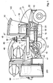
Der in Fig.1 dargestellte Feldhäcksler 100 zeigt ein Fahrgestell 10, auf dem eine
Fahrerkabine 30 angebracht ist. Neben der Kabine 30 ist auf dem Fahrgestell 10 das
obere Ende eines aufsteigenden Auswurfschachtes 46 angeordnet, der sich von
einer Häckseltrommel 43 innerhalb des Fahrgestell 10 bis oberhalb des Fahrgestells
10 erstreckt. Die Fahrerkabine 30 steht in einer Straßenbetriebsposition 31 etwa
mittig zwischen einer ersten Achseinheit 12 und dem Auswurfschacht 46, der Blick
des Fahrers ist beim Steuern in Richtung der ersten Achseinheit 12 gerichtet. Die
Fahrerkabine 30 ist auf einer Schwenkvorrichtung 50 angebracht, die um eine
vertikale Drehachse 51 horizontal schwenkbar ist. Die Schwenkvorrichtung 50 ist als
längenveränderlicher gerader Schwenkarm 55 ausgebildet, an dessen äußerem
Ende die Fahrerkabine 30 um die vertikale Drehachse 53 drehbar gelagert ist. Die
Drehachse 51 und die Schwenkvorrichtung 50 liegen vor dem Auswurfschacht,
sodass beim Schwenken der Fahrerkabine 30 um 180° um den Auswurfschacht 46
herum weder die Fahrerkabine 30 noch die Schwenkvorrichtung 50 den
Auswurfschacht 46 berühren bzw. einen Sicherheitsabstand unterschreiten.The
Auf dem Auswurfschacht 46 ist ein mit einem Drehkranz 47 um eine vertikale
Drehachse 49 drehbarer Auswurfkrümmer 48 angeflanscht, der zusätzlich um eine
horizontale Achse 58 in der Höhe verstellbar ist. Der Auswurfkrümmer 48 ist in eine
Straßenbetriebsposition 60 in Richtung einer weiteren Achseinheit 11 gestellt.On the
Das Fahrgestell 10 des Feldhäckslers wird von den beiden Achseinheiten 11, 12
getragen. Die erste Achseinheit 12 ist mit kleineren Rädern als die weitere
Achseinheit 11 bestückt. In der Nähe der ersten Achseinheit 12 trägt das Fahrgestell
10 eine Antriebseinheit 20. Fig.1 zeigt die Antriebseinheit 20 im Teilschnitt, sie
besteht aus einem Motor 21, einem Getriebe 22 und einem Kühlsystem 23. Der
größte Anteil der Last der Antriebseinheit 20 ruht auf der ersten Achseinheit 12,
wobei der Schwerpunkt der Antriebseinheit 20 sich durch die Anordnung des Motors
21 und des Getriebes 22 etwa in Höhe der ersten Achseinheit 12 befindet. Im
Bereich der zweiten Achseinheit 11 ist eine Funktionsbaugruppe 40 untergebracht,
die aus einem Einzugschacht 41 besteht, in dem mehrere Vorpresswalzen 42
drehbar gelagert sind, und die einen diesem Einzugschacht 41 nachgeordneten
annähernd vertikal verlaufenden Auswurfschacht 46 beinhaltet, in dem nacheinander
eine Häckseltrommel 43, ein nachgeschalteter Corn-Cracker (nicht dargestellt) und
ein Nachbeschleuniger 45 angeordnet sind. Es liegt im Rahmen der Erfindung, dass
dem Auswurfschacht 46 weitere nicht beschriebene Organe zugeordnet sein können.The
Dem Einzugschacht 41 ist ein an sich bekanntes und ein an folgender Stelle noch
näher erläutertes Vorsatzgerät 200 zugeordnet. Der größte Anteil der Lasten der
Funktionsbaugruppe 40 und des Vorsatzgerätes 200 ruht auf der zweiten
Achseinheit 11.The
Das Vorsatzgerät 200 ist in eine Transportposition 220 zusammengeklappt und dabei
teilweise über dem Traggestell 10 angeordnet. The
Fig.2 zeigt eine schematische Draufsicht des erfindungsgemäßen Feldhäckslers 100
mit einem reihenunabhängigen Vorsatzgerät 200.2 shows a schematic top view of the
Die Fahrerkabine 30 steht in einer Häckselbetriebposition 32 über der Achseinheit 11
und der Blick des Fahrers ist beim Steuern auf das Vorsatzgerät 200 gerichtet. Der
Auswurfkrümmer 43 ist in eine Häckselbetriebposition 65 quer zur Längsachse des
Feldhäckslers 100 gestellt, aus die er beim Häckseln um die Drehachse 49 gegen
den Urzeigersinn um 180° Grad verdrehbar ist. Die Schwenkvorrichtung 50 und der
Drehpunkt 51 sind neben dem Auswurfschacht 46 angeordnet.The driver's
Beim Positionswechsel der Fahrerkabine 30 und des Auswurfkrümmers 48 aus den
Straßenbetriebspositionen 31, 60 in Häckselbetriebpositionen 32, 65 und beim
Wechsel zurück werden die Fahrerkabine 30 und der Auswurfkrümmer 48
gleichsinnig um den Auswurfschacht 46 herum bewegt. Anschläge verhindern, dass
die Fahrerkabine 30 und der Auswurfkrümmer 48 kollidieren. Die Bewegung der
Fahrerkabine 30 und des Auswurfkrümmers 48 sind bei der Positionsänderung
aneinander gekoppelt. Die Bewegungen werden beispielsweise über Sensoren
elektronisch überwacht, die ihre ermittelten Daten an eine Auswerteeinheit
weitergeben. Die Auswerteeinheit wertet die Daten aus und gibt z.B. durch Software
unterstützt die Bewegungen für den Auswurfkrümmer 48 und die Fahrerkabine 30
vor.When changing the position of the driver's
Die Fahrerkabine 30 ist über einen Aufstieg 16 in der Nähe der Achseinheit 11 auf
der rechten Seite des Feldhäckslers 100 erreichbar.The driver's
Das auseinandergeklappte Vorsatzgerät 200, das stirnseitig am Fahrgestell 10 vor
den Einzugsschacht 41 montiert ist, befindet sich in einer Arbeitsposition 210. Das
Vorsatzgerät 200 ragt über die Breite des Feldhäckslers 100 hinaus, er ist in dieser
Position unterhalb der Tragebene 13 angeordnet. Der Schwerpunkt des parallel zur
Achseinheit 11 liegenden auseinandergeklappten Vorsatzgerätes 200 liegt vor der
Achseinheit 11 außerhalb des Fahrgestells 10.The unfolded
Der auf dem Feld stehende Mais wird vom Vorsatzgerät 200 geschnitten und zum
Einzugsschacht 41 transportiert, der Mais wird von der Funktionsbaugruppe 40
aufbereitet und das dabei entstehende Gut verlässt die Funktionsbaugruppe 40 über
den Auswurfschacht 46. Der sich direkt an den Auswurfschacht 46 anschließende
Auswurfkrümmer 48 leitet das Gut zum Überladen in die gewünschte Richtung.The corn standing in the field is cut by the
Der Feldhäcksler 100 der Fig. 2 wird beim Ernten vorzugsweise in einer
Häckselfahrtrichtung HF auf dem Feld gefahren, selbstverständlich kann der
Feldhäcksler 100 zum Rangieren rückwärts, in die entgegengesetzte Richtung
fahren.The
Fig.3 zeigt eine schematische Draufsicht des erfindungsgemäßen Feldhäckslers 100
mit einem reihenunabhängigen Vorsatzgerät 200 in einer hochgeklappten
Transportposition 220. Der hochgeklappte Vorsatzgerät 200 ist schmaler als die
größte Breite des Feldhäckslers 100.3 shows a schematic top view of the
Die Fahrerkabine 30 ist in der dargestellten Straßenbetriebposition über einen
zweiten rechtsseitigen Aufstieg 17 erreichbar, der zwischen den Achseinheiten 11,
12 am Traggestell 10 angebracht ist.The driver's
Der Feldhäcksler 100 der Fig. 3 wird vorzugsweise in einer Straßenfahrtrichtung SF
auf der Straße gefahren, selbstverständlich kann der Feldhäcksler 100 zum
Rangieren rückwärts, in die entgegengesetzte Richtung fahren.The
Der Wechsel von den Straßenbetriebpositionen 31, 60 in die Häckselbetriebpositionen 32, 65 erfolgt beim in Fig.2 und Fig.3 dargestelltem Feldhäcksler 100 im Uhrzeigersinn, der umgekehrte Wechsel der Positionen erfolgt gegen den Uhrzeigersinn.The change from the road operating positions 31, 60 to the chopping operating positions 32, 65 takes place in the forage harvester shown in FIGS. 2 and 3 100 clockwise, the positions change in reverse to the Clockwise.
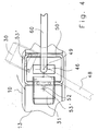
Fig. 4 zeigt eine zweite Ausführungsform der Schwenkvorrichtung 50'. Um den
Auswurfschacht 46 ist auf der Fahrgestellebene 13 eine Verschiebeführung 50'
angebracht, auf der die Fahrerkabine 30 über einen geraden Gelenkarm 52
angebracht ist. Der Gelenkarm 52 ist am inneren Ende in der Verschiebeführung
50'verschiebbar angebracht. Am äußeren Ende des Gelenkarms 52 ist die
Fahrerkabine 30 um eine vertikale Drehachse 53' drehbar gelagert. Die Kabine 50
wird um einen Bewegungsmittelpunkt 51' verschwenkt, der mit der Drehachse 49 des
Auswurfkrümmers koaxial ist. Diese Ausführungsform ermöglicht einen vollständigen
teilweise rotatorischen und teilweise translatorischen Umlauf der Fahrerkabine 30 um
den Auswurfschacht 46 herum. 4 shows a second embodiment of the swivel device 50 '. To the
Beim Betrieb auf der Straße in Straßenfahrtrichtung SF zeigt sich die Verteilung der
Lasten und die Umkehr der Fahrtrichtung besonders beim Bremsen aus hohen
Geschwindigkeiten als besonders nützlich. Bei starker Verzögerung aus hoher
Geschwindigkeit verhindert das Gewicht der Achseinheit 11, der Funktionsbaugruppe
40 und des Vorsatzgerätes 200, dass die Achseinheit 11 des Feldhäcksler 100 von
der Straße abhebt.When operating on the road in the direction of travel SF, the distribution of the
Loads and reversing the direction of travel especially when braking from high
Speeds as particularly useful. In the case of strong deceleration from high
Speed prevents the weight of the
Es liegt im Rahmen der Erfindung, dass abweichend vom dargestellten
Ausführungsbeispiel in den Fig. 1 bis 3 die Aufstiege 16, 17 spiegelbildlich am
Traggestell 10 angebracht und die Bewegungsrichtungen der Kabine 30 und des
Auswurfkrümmers 48 umgekehrt werden. It is within the scope of the invention that deviates from that shown
Embodiment in FIGS. 1 to 3, the
- 100100
- FeldhäckslerForage
- 1010
- Fahrgestellchassis
- 1111
- Erste AchseinheitFirst axis unit
- 1212
- Weitere AchseinheitAnother axle unit
- 1616
- Aufstiegrise
- 1717
- Aufstiegrise
- 2020
- Antriebseinheitdrive unit
- 2121
- Motorengine
- 2222
- Getriebetransmission
- 2323
- Kühlsystemcooling system
- 2424
- ArbeitsorgananordnungWorking body arrangement
- 3030
- Fahrerkabinecab
- 3131
- Straßenbetriebposition FahrerkabineRoad operating position cab
- 3232
- Häckslerbetriebposition FahrerkabineChopper operating position cab
- 4040
- Funktionsbaugruppefunction module
- 4141
- Einzugschachtchute
- 4242
- Vorpresswalzecompression roller
- 4343
- Häckseltrommelcutterhead
- 4444
- Corn-CrackerCorn crackers
- 4545
- Nachbeschleunigerpost-accelerator
- 4646
- Auswurfschachtchute
- 4747
- Drehkranzslewing ring
- 4848
- Auswurfkrümmerchute
- 4949
- Drehachseaxis of rotation
- 5050
- Schwenkvorrichtungswivel device
- 50'50 '
- Verschiebeführungdisplacement guide
- 5151
- Drehachseaxis of rotation
- 51'51 '
- BewegungsmittelpunktCenter of motion
- 5252
- Gelenkarmarticulated arm
- 5353
- Drehachseaxis of rotation
- 53'53 '
- Drehachseaxis of rotation
- 5555
- Schwenkarmswivel arm
- 6060
- Straßenbetriebposition AuswurfkrümmerRoad operating position chute
- 6565
- Häckselbetriebposition AuswurfkrümmerHäckselbetriebposition chute
- 200200
- Vorsatzgerätheader
- 210210
- Arbeitsposition Vorsatzgerätworking position header
- 220220
- Transportposition Vorsatzgerättransport position header
- SFSF
- StraßenfahrtrichtungRoad direction
- HFHF
- HäckselfahrtrichtungHäckselfahrtrichtung
Claims (23)
dadurch gekennzeichnet, dass
die Fahrerkabine (30) aus zumindest einer Straßenbetriebposition (31) in zumindest eine Häckselbetriebposition (32) und umgekehrt bewegbar ist und dass die Kabine (30) bei diesen Positionsänderungen wenigstens eine Arbeitsorgananordnung (24) umgreift.Self-propelled forage harvester (100) with a driver's cab (30) arranged on a chassis (10) and an ascending chute (46) extending from a chopper drum (43) within the chassis (10) to above the chassis (10),
characterized in that
the driver's cab (30) can be moved from at least one road operating position (31) into at least one chopping operating position (32) and vice versa, and that the cab (30) engages around at least one working organ arrangement (24) during these changes in position.
dadurch gekennzeichnet, dass
die Arbeitsorgananordnung (24) der Auswurfschacht (46) ist.Self-propelled forage harvester according to claim 1,
characterized in that
the working organ arrangement (24) of the chute (46).
dadurch gekennzeichnet, dass
die Änderung der Positionen durch verschieben und/oder verschwenken der Kabine (30) erfolgt.Self-propelled forage harvester according to at least one of the preceding claims 1 to 2,
characterized in that
the positions are changed by moving and / or pivoting the cabin (30).
dadurch gekennzeichnet, dass
die Schwenkvorrichtung (50) mit einem längenveränderlichen Schwenkarm (55) ausgestattet ist. Self-propelled forage harvester according to at least one of the preceding claims 1 to 3,
characterized in that
the swivel device (50) is equipped with a variable-length swivel arm (55).
dadurch gekennzeichnet, dass
die Schwenkvorrichtung (50) eine Drehachse (51) aufweist, die außerhalb des Auswurfschachtes (46) angeordnet ist.Self-propelled forage harvester according to at least one of the preceding claims 1 to 4,
characterized in that
the swivel device (50) has an axis of rotation (51) which is arranged outside the chute (46).
dadurch gekennzeichnet, dass
die Fahrerkabine (30) in der Häckselbetriebposition (32) und in der Straßenbetriebsposition (31) über Aufstiege (16, 17) erreichbar ist, die am Fahrgestell (10) angeordnet sind.Self-propelled forage harvester according to at least one of the preceding claims 1 to 5,
characterized in that
the driver's cab (30) in the chopper operating position (32) and in the road operating position (31) can be reached via steps (16, 17) which are arranged on the chassis (10).
dadurch gekennzeichnet, dass
ein auf dem Auswurfschacht (46) angeflanschter Auswurfkrümmer (48) um eine horizontale Achse (58) höhenverschwenkbar ist.Self-propelled forage harvester according to at least one of the preceding claims 1 to 6,
characterized in that
a discharge chuck (48) flanged onto the discharge chute (46) can be pivoted in height about a horizontal axis (58).
dadurch gekennzeichnet, dass
der Auswurfkrümmer (48) aus einer Häckselbetriebposition (65) in eine Straßenbetriebposition (60) bewegbar ist.Self-propelled forage harvester according to at least one of the preceding claims 1 to 7,
characterized in that
the chute (48) is movable from a chopper operating position (65) to a road operating position (60).
dadurch gekennzeichnet, dass
die Fahrerkabine (30) und der Auswurfkrümmer (48) gleichsinnig um den Auswurfschacht (46) positionierbar sind. Self-propelled forage harvester according to at least one of the preceding claims 1 to 8,
characterized in that
the driver's cabin (30) and the chute (48) can be positioned in the same direction around the chute (46).
dadurch gekennzeichnet, dass
die Bewegung der Fahrerkabine (30) und die Bewegung des Auswurfkrümmers (48) aneinander gekoppelt sind.Self-propelled forage harvester according to at least one of the preceding claims 1 to 9,
characterized in that
the movement of the driver's cab (30) and the movement of the discharge spout (48) are coupled to one another.
dadurch gekennzeichnet, dass
die Bewegung des Auswurfkrümmer (48) in horizontaler und/oder vertikaler Richtung durch Anschläge begrenzt wird.Self-propelled forage harvester according to at least one of the preceding claims 1 to 10,
characterized in that
the movement of the chute (48) in the horizontal and / or vertical direction is limited by stops.
dadurch gekennzeichnet, dass
die Fahrerkabine (30) in der Straßenbetriebposition (31) etwa mittig zwischen den Achseinheiten (11, 12) angeordnet ist.Self-propelled forage harvester according to at least one of the preceding claims 1 to 11,
characterized in that
the driver's cab (30) in the road operating position (31) is arranged approximately centrally between the axle units (11, 12).
dadurch gekennzeichnet, dass
die Fahrerkabine (30) neben dem Auswurfschacht (46) angeordnet ist.Self-propelled forage harvester according to at least one of the preceding claims 1 to 12,
characterized in that
the driver's cabin (30) is arranged next to the chute (46).
dadurch gekennzeichnet, dass
die Kabine (30) auf einer Verschiebeführung (50') verschieblich befestigt ist und dabei um eine vertikale Drehachse (53') schwenkbar gelagert ist. Self-propelled forage harvester according to at least one of the preceding claims 1 to 13,
characterized in that
the cabin (30) is slidably mounted on a sliding guide (50 ') and is pivotally mounted about a vertical axis of rotation (53').
dadurch gekennzeichnet, dass
die Drehachse (49) des Auswurfkrümmers (48) und der Bewegungsmittelpunkt (51') der Verschiebevorrichtung (50') koaxial sind.Self-propelled forage harvester according to at least one of the preceding claims 1 to 14,
characterized in that
the axis of rotation (49) of the discharge spout (48) and the center of movement (51 ') of the displacement device (50') are coaxial.
dadurch gekennzeichnet, dass
zwischen der Verschiebeführung (50') und der Fahrerkabine (30) ein Gelenkarm (52) angelenkt ist.Self-propelled forage harvester according to at least one of the preceding claims 1 to 15,
characterized in that
an articulated arm (52) is articulated between the displacement guide (50 ') and the driver's cabin (30).
dadurch gekennzeichnet, dass
zumindest eine Funktionsbaugruppe (40) und/oder ein Vorsatzgerät (200) im Wesentlichen im Bereich der zumindest einen ersten Achseinheit (11) angeordnet ist und eine Antriebseinheit (20) im Wesentlichen im Bereich der zumindest einen weiteren Achseinheit (12) angeordnet ist.Self-propelled forage harvester (100) with a driver's cab (30) arranged on a chassis (10) and an ascending chute (46) extending from a chopper drum (43) within the chassis (10) to above the chassis (10),
characterized in that
at least one functional assembly (40) and / or an attachment (200) is arranged essentially in the area of the at least one first axle unit (11) and a drive unit (20) is arranged essentially in the area of the at least one further axle unit (12).
dadurch gekennzeichnet, dass
die Funktionsbaugruppe (40) von einem Einzugschacht (41) und einem mit diesem in Wirkverbindung stehenden Auswurfschacht (46) gebildet wird.Self-propelled forage harvester according to claim 17,
characterized in that
the functional assembly (40) is formed by an intake shaft (41) and an ejection shaft (46) which is operatively connected to the latter.
dadurch gekennzeichnet, dass
der Auswurfschacht (46) mehrere Arbeitsorgane aufnimmt. Self-propelled forage harvester according to at least one of the preceding claims 17 to 18,
characterized in that
the chute (46) accommodates several working elements.
dadurch gekennzeichnet, dass
die Arbeitsorgane Häckseltrommel (43), Corn-Cracker (44) und Nachbeschleuniger (45) sein können.Self-propelled forage harvester according to claim 19,
characterized in that
the working elements can be chopper drum (43), corn cracker (44) and post-accelerator (45).
dadurch gekennzeichnet, dass
der Einzugschacht (41) mehrere Vorpresswalzen (42) aufnimmt.Self-propelled forage harvester according to claim 18,
characterized in that
the feed chute (41) receives several pre-pressing rollers (42).
dadurch gekennzeichnet, dass
die Antriebseinheit (20) aus einem Motor (21) und einem Getriebe (22) und einem Kühler (23) bestehen können.Self-propelled forage harvester according to claim 17,
characterized in that
the drive unit (20) can consist of a motor (21) and a transmission (22) and a cooler (23).
dadurch gekennzeichnet, dass
das Vorsatzgerät (200) in einer Transportposition (220) wenigstens teilweise in den Bereich der Lage der Kabine (30) in Häckselbetriebposition (32) verschwenkbar ist.Self-propelled forage harvester according to claim 17,
characterized in that
the attachment (200) in a transport position (220) is at least partially pivotable into the area of the position of the cabin (30) in the chopper operating position (32).
Applications Claiming Priority (2)
| Application Number | Priority Date | Filing Date | Title |
|---|---|---|---|
| DE10317816A DE10317816A1 (en) | 2003-04-16 | 2003-04-16 | Forage harvester with positionable driver's cab |
| DE10317816 | 2003-04-16 |
Publications (3)
| Publication Number | Publication Date |
|---|---|
| EP1468598A2 true EP1468598A2 (en) | 2004-10-20 |
| EP1468598A3 EP1468598A3 (en) | 2009-08-26 |
| EP1468598B1 EP1468598B1 (en) | 2012-12-19 |
Family
ID=32892413
Family Applications (1)
| Application Number | Title | Priority Date | Filing Date |
|---|---|---|---|
| EP04008212A Expired - Lifetime EP1468598B1 (en) | 2003-04-16 | 2004-04-05 | Forage harvester with positionable driver's cab |
Country Status (3)
| Country | Link |
|---|---|
| US (2) | US7003938B2 (en) |
| EP (1) | EP1468598B1 (en) |
| DE (1) | DE10317816A1 (en) |
Cited By (8)
| Publication number | Priority date | Publication date | Assignee | Title |
|---|---|---|---|---|
| FR2881609A1 (en) * | 2005-02-09 | 2006-08-11 | Kuhn Sa Sa | AGRICULTURAL ENGINE FOR THE CUTTING OF PRODUCTS COMPRISING A CARRIER VEHICLE AND WORKING UNITS |
| EP1779717A1 (en) * | 2005-10-28 | 2007-05-02 | Claas Saulgau Gmbh | Improving the visibility in self-propelled working machines |
| EP1894463A1 (en) | 2006-08-28 | 2008-03-05 | CLAAS Selbstfahrende Erntemaschinen GmbH | Agricultural harvester with an excess load device |
| EP1894462A1 (en) | 2006-08-28 | 2008-03-05 | CLAAS Selbstfahrende Erntemaschinen GmbH | Agricultural carrier vehicle |
| DE102007035745A1 (en) * | 2007-07-31 | 2009-02-05 | Maschinenfabrik Kemper Gmbh & Co. Kg | Harvest header with side cover |
| EP1671837A3 (en) * | 2004-11-08 | 2009-11-25 | CLAAS Selbstfahrende Erntemaschinen GmbH | Pivotable driver seat within a driver cabin of an agricultural vehicle |
| CN105532160A (en) * | 2016-02-02 | 2016-05-04 | 张东军 | Self-propelled efficient rhizoma corydalis selecting harvester |
| AT16978U3 (en) * | 2020-09-08 | 2021-10-15 | Manfred Saller | Chopper |
Families Citing this family (19)
| Publication number | Priority date | Publication date | Assignee | Title |
|---|---|---|---|---|
| FR2837347B1 (en) * | 2002-03-21 | 2004-07-30 | Kuhn Sa | AGRICULTURAL MOWER COMPRISING A CARRIER VEHICLE AND SEVERAL WORKING UNITS |
| DE102004057048A1 (en) * | 2004-11-25 | 2006-06-08 | Claas Selbstfahrende Erntemaschinen Gmbh | Harvester |
| SG158884A1 (en) | 2005-01-14 | 2010-02-26 | Schering Corp | An exo-selective synthesis of himbacine analogs |
| EP1716742A1 (en) * | 2005-04-27 | 2006-11-02 | Claas Saulgau Gmbh | Apparatus for harvesting |
| FR2885484B1 (en) * | 2005-05-10 | 2007-06-15 | Kuhn Sa Sa | AGRICULTURAL ENGINE COMPRISING A MOTOR VEHICLE AND SEVERAL WORK UNITS INTENDED TO CUT PLANT PRODUCTS |
| FR2895211B1 (en) * | 2005-12-22 | 2009-11-20 | Kuhn Sa | AGRICULTURAL ENGINE COMPRISING AN IMPROVED COUPLING |
| EP1869968B1 (en) * | 2006-06-22 | 2009-11-18 | Maasland N.V. | Crop-processing device comprising a pick-up/cutting device |
| TWI367112B (en) * | 2006-06-30 | 2012-07-01 | Schering Corp | Immediate-release tablet formulations of a thrombin receptor antagonist |
| MX2009006873A (en) * | 2006-12-22 | 2009-07-03 | Schering Corp | Disintegration promoters in solid dose wet granulation formulations. |
| US7806757B2 (en) * | 2008-07-16 | 2010-10-05 | Deere & Company | Dual sided belted unloader |
| DE102008049130A1 (en) * | 2008-09-26 | 2010-04-01 | Claas Selbstfahrende Erntemaschinen Gmbh | Agricultural harvester |
| EP2440191A2 (en) | 2009-06-08 | 2012-04-18 | Schering Corporation | A thrombin receptor antagonist and clopidogrel fixed dose tablet |
| US8197312B2 (en) * | 2009-12-04 | 2012-06-12 | Cnh America Llc | Extension for an agricultural combine unloader tube |
| US20130019580A1 (en) * | 2011-07-20 | 2013-01-24 | Anderson Noel W | Bidirectional harvesting system |
| WO2014046685A1 (en) * | 2012-09-24 | 2014-03-27 | Deere & Company | Bidirectional harvesting system |
| USD797813S1 (en) * | 2016-02-22 | 2017-09-19 | Claas Kgaa Mbh | Harvester |
| US10785913B2 (en) * | 2018-04-30 | 2020-09-29 | Orchard-Rite Ltd., Inc. | Two-piece harvester having a shaker and a receiver for harvesting tree fruits or nuts |
| NL2021519B1 (en) * | 2018-08-30 | 2020-04-24 | Ploeger Oxbo Europe B V | Self-propelled agricultural machine, for example a self-propelled belt rake |
| DE102019212647A1 (en) * | 2019-08-23 | 2021-02-25 | Deere & Company | Forage harvester with discharge spout and position-adjustable cab |
Citations (1)
| Publication number | Priority date | Publication date | Assignee | Title |
|---|---|---|---|---|
| DE2046552A1 (en) | 1969-09-23 | 1971-04-01 | C van der LeIy N V , Maasland (Niederlande) | Tractor with a sliding driver's seat |
Family Cites Families (29)
| Publication number | Priority date | Publication date | Assignee | Title |
|---|---|---|---|---|
| US3182605A (en) * | 1963-10-07 | 1965-05-11 | Lawrence J Brasher | Vehicle control |
| NL6401807A (en) * | 1964-02-26 | 1965-08-27 | ||
| NL6402194A (en) * | 1964-03-05 | 1965-09-06 | ||
| US3352093A (en) * | 1965-06-08 | 1967-11-14 | Sperry Rand Corp | Forage harvester |
| CH519291A (en) * | 1968-10-07 | 1972-02-29 | Lely Nv C Van Der | Self-propelled agricultural machine that can be used as a tractor |
| NL158447B (en) * | 1968-10-07 | 1978-11-15 | Lely Nv C Van Der | TRACTOR FOR AGRICULTURAL PURPOSES WITH A LOADING SURFACE. |
| US3825138A (en) * | 1972-10-24 | 1974-07-23 | Mathews B | Unloader for the grain bin of a combine |
| GB1518798A (en) * | 1974-10-05 | 1978-07-26 | Coles Cranes Ltd | Rough terrain cranes (swingable cb) |
| FR2340850A1 (en) * | 1976-02-10 | 1977-09-09 | Bidon Jacques | TRACTOR VEHICLE, ESPECIALLY FOR AGRICULTURAL USE |
| DE3024650A1 (en) * | 1980-06-30 | 1982-02-25 | Claas Ohg, 4834 Harsewinkel | SELF-DRIVING AGRICULTURAL MULTI-PURPOSE VEHICLE WITH ADJUSTABLE DRIVER'S CAB |
| DE3024664A1 (en) * | 1980-06-30 | 1982-02-04 | Claas Ohg, 4834 Harsewinkel | AGRICULTURAL MULTIPURPOSE VEHICLE |
| US4355690A (en) * | 1980-12-18 | 1982-10-26 | Deere & Company | Stack folding outrigger system |
| SE425648B (en) * | 1981-03-13 | 1982-10-25 | Kockums Ind Ab | WHEEL-WORKED VEHICLE WITH LOADS |
| US4409780A (en) * | 1982-03-11 | 1983-10-18 | Kansas State University Research Foundation | Folding header assembly |
| DE3234657A1 (en) * | 1982-09-18 | 1984-03-22 | Claas Ohg, 4834 Harsewinkel | Field chopper |
| NL8203654A (en) * | 1982-09-21 | 1984-04-16 | Patent Concern Nv | TRACTOR, IN PARTICULAR A TRACTOR FOR AGRICULTURAL PURPOSES. |
| DE3346309A1 (en) * | 1983-01-04 | 1984-07-12 | Karl-Heinz 6711 Heuchelheim Obermaier | Motor vehicle with positionally variable driver's cab |
| US4903470A (en) * | 1987-09-14 | 1990-02-27 | Claas Ohg | Self-propelling harvester thresher with two-part cutting mechanism |
| DE3911524A1 (en) * | 1989-04-08 | 1990-10-11 | Claas Ohg | AGRICULTURAL VEHICLE |
| DE19523255A1 (en) * | 1995-06-27 | 1997-01-02 | Claas Saulgau Gmbh | Header on agricultural machines for picking up and moving on straw crops, for example maize plants |
| DE19524752B4 (en) * | 1995-07-07 | 2004-08-12 | Claas Kgaa Mbh | Device and method for measuring throughput in an agricultural harvesting machine |
| US6032444A (en) * | 1997-06-04 | 2000-03-07 | Hay & Forage Industries | Non-row-sensitive forage harvester |
| CA2240869C (en) * | 1998-06-17 | 2005-08-23 | Bourgault Industries Ltd. | Grain cart drive assembly |
| DE19903471C1 (en) * | 1999-01-29 | 2000-06-08 | Deere & Co | Crop machine throughput measurement arrangement derives throughput from distance between pre-baling rollers and crop speed, corrects for displacement force on pre-baling roller |
| DE19918551B4 (en) * | 1999-04-23 | 2015-04-02 | Deere & Company | harvester |
| DE19958280A1 (en) * | 1999-12-03 | 2001-06-13 | Peter Gallersdoerfer | Automotive agricultural machine, e.g. combine harvester has cutting tool at one end and cab from which it can be controlled in working direction and second cab at other end for road driving |
| DE20007994U1 (en) * | 2000-05-04 | 2001-09-13 | Krone Bernhard Gmbh Maschf | Self-propelled harvester, especially forage harvesters |
| DE10021664B4 (en) * | 2000-05-04 | 2004-05-06 | Maschinenfabrik Bernard Krone Gmbh | Harvester, especially self-propelled forage harvesters |
| DE10142978A1 (en) * | 2001-09-01 | 2003-03-20 | Kemper Gmbh Maschf | header |
-
2003
- 2003-04-16 DE DE10317816A patent/DE10317816A1/en not_active Withdrawn
-
2004
- 2004-04-05 US US10/818,484 patent/US7003938B2/en not_active Expired - Fee Related
- 2004-04-05 EP EP04008212A patent/EP1468598B1/en not_active Expired - Lifetime
-
2005
- 2005-05-10 US US11/125,633 patent/US7222480B2/en not_active Expired - Fee Related
Patent Citations (1)
| Publication number | Priority date | Publication date | Assignee | Title |
|---|---|---|---|---|
| DE2046552A1 (en) | 1969-09-23 | 1971-04-01 | C van der LeIy N V , Maasland (Niederlande) | Tractor with a sliding driver's seat |
Cited By (11)
| Publication number | Priority date | Publication date | Assignee | Title |
|---|---|---|---|---|
| EP1671837A3 (en) * | 2004-11-08 | 2009-11-25 | CLAAS Selbstfahrende Erntemaschinen GmbH | Pivotable driver seat within a driver cabin of an agricultural vehicle |
| FR2881609A1 (en) * | 2005-02-09 | 2006-08-11 | Kuhn Sa Sa | AGRICULTURAL ENGINE FOR THE CUTTING OF PRODUCTS COMPRISING A CARRIER VEHICLE AND WORKING UNITS |
| EP1690446A1 (en) * | 2005-02-09 | 2006-08-16 | Kuhn S.A. | Agricultural machine for cutting products |
| US7543433B2 (en) | 2005-02-09 | 2009-06-09 | Kuhn S.A. | Agricultural machine for cutting products |
| CN100592867C (en) * | 2005-02-09 | 2010-03-03 | 库恩股份有限公司 | Agricultural machine for cutting products |
| EP1779717A1 (en) * | 2005-10-28 | 2007-05-02 | Claas Saulgau Gmbh | Improving the visibility in self-propelled working machines |
| EP1894463A1 (en) | 2006-08-28 | 2008-03-05 | CLAAS Selbstfahrende Erntemaschinen GmbH | Agricultural harvester with an excess load device |
| EP1894462A1 (en) | 2006-08-28 | 2008-03-05 | CLAAS Selbstfahrende Erntemaschinen GmbH | Agricultural carrier vehicle |
| DE102007035745A1 (en) * | 2007-07-31 | 2009-02-05 | Maschinenfabrik Kemper Gmbh & Co. Kg | Harvest header with side cover |
| CN105532160A (en) * | 2016-02-02 | 2016-05-04 | 张东军 | Self-propelled efficient rhizoma corydalis selecting harvester |
| AT16978U3 (en) * | 2020-09-08 | 2021-10-15 | Manfred Saller | Chopper |
Also Published As
| Publication number | Publication date |
|---|---|
| US20050210850A1 (en) | 2005-09-29 |
| EP1468598A3 (en) | 2009-08-26 |
| US7222480B2 (en) | 2007-05-29 |
| US20040216437A1 (en) | 2004-11-04 |
| US7003938B2 (en) | 2006-02-28 |
| DE10317816A1 (en) | 2004-11-04 |
| EP1468598B1 (en) | 2012-12-19 |
Similar Documents
| Publication | Publication Date | Title |
|---|---|---|
| EP1468598A2 (en) | Forage harvester with positionable driver's cab | |
| DE69925469T2 (en) | TILTING COMBINE | |
| DE1949978A1 (en) | Universal tractor | |
| EP1444881A2 (en) | Drive system for the harvesting attachment of a harvesting machine | |
| EP0827684A2 (en) | Self-propelled agricultural harvesting machine | |
| EP1440617A1 (en) | Drive system for a harvester head | |
| DE1950497B2 (en) | Tractor with a loading area for payloads | |
| EP1618777B1 (en) | Discharge device of an agricultural harvesting machine | |
| DE2252105A1 (en) | HARVESTER | |
| EP1048195A1 (en) | Pivoting device for support wheels | |
| DE4340384B4 (en) | Hay-making machine | |
| EP1894462B1 (en) | Agricultural carrier vehicle | |
| EP1894463B1 (en) | Agricultural harvester with an excess load device | |
| DE19802199A1 (en) | Combine harvester grain tank discharger | |
| EP1932414B1 (en) | Mowing machine to be placed on the front end of an agricultural automobile | |
| EP1093710B1 (en) | Tractor with forward mounted mowing device | |
| EP0736244A2 (en) | Harvesting machine with compensation means for hillside working | |
| DE3713474A1 (en) | HAY ADVERTISING MACHINE | |
| EP0331070A1 (en) | Multi-purpose agricultural vehicle | |
| DE2018070A1 (en) | Multipurpose motor vehicles, in particular equipment carriers | |
| DE3205748C2 (en) | Self-propelled agricultural utility vehicle | |
| EP1145620B1 (en) | Haymaking machine | |
| EP0698338B1 (en) | Harvesting machine with compensation means for hillside working | |
| DE60315094T2 (en) | Lifting device for an industrial truck | |
| EP0543389B1 (en) | Self-propelled agricultural tractor with three axles |
Legal Events
| Date | Code | Title | Description |
|---|---|---|---|
| PUAI | Public reference made under article 153(3) epc to a published international application that has entered the european phase |
Free format text: ORIGINAL CODE: 0009012 |
|
| AK | Designated contracting states |
Kind code of ref document: A2 Designated state(s): AT BE BG CH CY CZ DE DK EE ES FI FR GB GR HU IE IT LI LU MC NL PL PT RO SE SI SK TR |
|
| AX | Request for extension of the european patent |
Extension state: AL HR LT LV MK |
|
| PUAL | Search report despatched |
Free format text: ORIGINAL CODE: 0009013 |
|
| AK | Designated contracting states |
Kind code of ref document: A3 Designated state(s): AT BE BG CH CY CZ DE DK EE ES FI FR GB GR HU IE IT LI LU MC NL PL PT RO SE SI SK TR |
|
| AX | Request for extension of the european patent |
Extension state: AL HR LT LV MK |
|
| 17P | Request for examination filed |
Effective date: 20100226 |
|
| AKX | Designation fees paid |
Designated state(s): AT BE BG CH CY CZ DE DK EE ES FI FR GB GR HU IE IT LI LU MC NL PL PT RO SE SI SK TR |
|
| 17Q | First examination report despatched |
Effective date: 20120413 |
|
| GRAP | Despatch of communication of intention to grant a patent |
Free format text: ORIGINAL CODE: EPIDOSNIGR1 |
|
| GRAS | Grant fee paid |
Free format text: ORIGINAL CODE: EPIDOSNIGR3 |
|
| GRAA | (expected) grant |
Free format text: ORIGINAL CODE: 0009210 |
|
| AK | Designated contracting states |
Kind code of ref document: B1 Designated state(s): AT BE BG CH CY CZ DE DK EE ES FI FR GB GR HU IE IT LI LU MC NL PL PT RO SE SI SK TR |
|
| REG | Reference to a national code |
Ref country code: GB Ref legal event code: FG4D Free format text: NOT ENGLISH |
|
| REG | Reference to a national code |
Ref country code: CH Ref legal event code: EP |
|
| REG | Reference to a national code |
Ref country code: AT Ref legal event code: REF Ref document number: 588881 Country of ref document: AT Kind code of ref document: T Effective date: 20130115 |
|
| REG | Reference to a national code |
Ref country code: DE Ref legal event code: R096 Ref document number: 502004013934 Country of ref document: DE Effective date: 20130214 |
|
| PG25 | Lapsed in a contracting state [announced via postgrant information from national office to epo] |
Ref country code: FI Free format text: LAPSE BECAUSE OF FAILURE TO SUBMIT A TRANSLATION OF THE DESCRIPTION OR TO PAY THE FEE WITHIN THE PRESCRIBED TIME-LIMIT Effective date: 20121219 Ref country code: ES Free format text: LAPSE BECAUSE OF FAILURE TO SUBMIT A TRANSLATION OF THE DESCRIPTION OR TO PAY THE FEE WITHIN THE PRESCRIBED TIME-LIMIT Effective date: 20130330 Ref country code: SE Free format text: LAPSE BECAUSE OF FAILURE TO SUBMIT A TRANSLATION OF THE DESCRIPTION OR TO PAY THE FEE WITHIN THE PRESCRIBED TIME-LIMIT Effective date: 20121219 |
|
| REG | Reference to a national code |
Ref country code: NL Ref legal event code: VDEP Effective date: 20121219 |
|
| PG25 | Lapsed in a contracting state [announced via postgrant information from national office to epo] |
Ref country code: SI Free format text: LAPSE BECAUSE OF FAILURE TO SUBMIT A TRANSLATION OF THE DESCRIPTION OR TO PAY THE FEE WITHIN THE PRESCRIBED TIME-LIMIT Effective date: 20121219 Ref country code: GR Free format text: LAPSE BECAUSE OF FAILURE TO SUBMIT A TRANSLATION OF THE DESCRIPTION OR TO PAY THE FEE WITHIN THE PRESCRIBED TIME-LIMIT Effective date: 20130320 |
|
| PG25 | Lapsed in a contracting state [announced via postgrant information from national office to epo] |
Ref country code: SK Free format text: LAPSE BECAUSE OF FAILURE TO SUBMIT A TRANSLATION OF THE DESCRIPTION OR TO PAY THE FEE WITHIN THE PRESCRIBED TIME-LIMIT Effective date: 20121219 Ref country code: BG Free format text: LAPSE BECAUSE OF FAILURE TO SUBMIT A TRANSLATION OF THE DESCRIPTION OR TO PAY THE FEE WITHIN THE PRESCRIBED TIME-LIMIT Effective date: 20130319 Ref country code: CY Free format text: LAPSE BECAUSE OF FAILURE TO SUBMIT A TRANSLATION OF THE DESCRIPTION OR TO PAY THE FEE WITHIN THE PRESCRIBED TIME-LIMIT Effective date: 20121219 Ref country code: CZ Free format text: LAPSE BECAUSE OF FAILURE TO SUBMIT A TRANSLATION OF THE DESCRIPTION OR TO PAY THE FEE WITHIN THE PRESCRIBED TIME-LIMIT Effective date: 20121219 Ref country code: EE Free format text: LAPSE BECAUSE OF FAILURE TO SUBMIT A TRANSLATION OF THE DESCRIPTION OR TO PAY THE FEE WITHIN THE PRESCRIBED TIME-LIMIT Effective date: 20121219 |
|
| PG25 | Lapsed in a contracting state [announced via postgrant information from national office to epo] |
Ref country code: PL Free format text: LAPSE BECAUSE OF FAILURE TO SUBMIT A TRANSLATION OF THE DESCRIPTION OR TO PAY THE FEE WITHIN THE PRESCRIBED TIME-LIMIT Effective date: 20121219 Ref country code: RO Free format text: LAPSE BECAUSE OF FAILURE TO SUBMIT A TRANSLATION OF THE DESCRIPTION OR TO PAY THE FEE WITHIN THE PRESCRIBED TIME-LIMIT Effective date: 20121219 Ref country code: PT Free format text: LAPSE BECAUSE OF FAILURE TO SUBMIT A TRANSLATION OF THE DESCRIPTION OR TO PAY THE FEE WITHIN THE PRESCRIBED TIME-LIMIT Effective date: 20130419 Ref country code: NL Free format text: LAPSE BECAUSE OF FAILURE TO SUBMIT A TRANSLATION OF THE DESCRIPTION OR TO PAY THE FEE WITHIN THE PRESCRIBED TIME-LIMIT Effective date: 20121219 |
|
| PLBE | No opposition filed within time limit |
Free format text: ORIGINAL CODE: 0009261 |
|
| STAA | Information on the status of an ep patent application or granted ep patent |
Free format text: STATUS: NO OPPOSITION FILED WITHIN TIME LIMIT |
|
| PG25 | Lapsed in a contracting state [announced via postgrant information from national office to epo] |
Ref country code: DK Free format text: LAPSE BECAUSE OF FAILURE TO SUBMIT A TRANSLATION OF THE DESCRIPTION OR TO PAY THE FEE WITHIN THE PRESCRIBED TIME-LIMIT Effective date: 20121219 |
|
| 26N | No opposition filed |
Effective date: 20130920 |
|
| PG25 | Lapsed in a contracting state [announced via postgrant information from national office to epo] |
Ref country code: MC Free format text: LAPSE BECAUSE OF FAILURE TO SUBMIT A TRANSLATION OF THE DESCRIPTION OR TO PAY THE FEE WITHIN THE PRESCRIBED TIME-LIMIT Effective date: 20121219 |
|
| REG | Reference to a national code |
Ref country code: CH Ref legal event code: PL |
|
| GBPC | Gb: european patent ceased through non-payment of renewal fee |
Effective date: 20130405 |
|
| PG25 | Lapsed in a contracting state [announced via postgrant information from national office to epo] |
Ref country code: IT Free format text: LAPSE BECAUSE OF FAILURE TO SUBMIT A TRANSLATION OF THE DESCRIPTION OR TO PAY THE FEE WITHIN THE PRESCRIBED TIME-LIMIT Effective date: 20121219 |
|
| REG | Reference to a national code |
Ref country code: DE Ref legal event code: R097 Ref document number: 502004013934 Country of ref document: DE Effective date: 20130920 |
|
| REG | Reference to a national code |
Ref country code: IE Ref legal event code: MM4A |
|
| PG25 | Lapsed in a contracting state [announced via postgrant information from national office to epo] |
Ref country code: GB Free format text: LAPSE BECAUSE OF NON-PAYMENT OF DUE FEES Effective date: 20130405 Ref country code: LI Free format text: LAPSE BECAUSE OF NON-PAYMENT OF DUE FEES Effective date: 20130430 Ref country code: CH Free format text: LAPSE BECAUSE OF NON-PAYMENT OF DUE FEES Effective date: 20130430 |
|
| REG | Reference to a national code |
Ref country code: FR Ref legal event code: ST Effective date: 20131231 |
|
| PG25 | Lapsed in a contracting state [announced via postgrant information from national office to epo] |
Ref country code: FR Free format text: LAPSE BECAUSE OF NON-PAYMENT OF DUE FEES Effective date: 20130430 |
|
| PG25 | Lapsed in a contracting state [announced via postgrant information from national office to epo] |
Ref country code: IE Free format text: LAPSE BECAUSE OF NON-PAYMENT OF DUE FEES Effective date: 20130405 |
|
| REG | Reference to a national code |
Ref country code: AT Ref legal event code: MM01 Ref document number: 588881 Country of ref document: AT Kind code of ref document: T Effective date: 20130405 |
|
| PG25 | Lapsed in a contracting state [announced via postgrant information from national office to epo] |
Ref country code: AT Free format text: LAPSE BECAUSE OF NON-PAYMENT OF DUE FEES Effective date: 20130405 |
|
| PG25 | Lapsed in a contracting state [announced via postgrant information from national office to epo] |
Ref country code: TR Free format text: LAPSE BECAUSE OF FAILURE TO SUBMIT A TRANSLATION OF THE DESCRIPTION OR TO PAY THE FEE WITHIN THE PRESCRIBED TIME-LIMIT Effective date: 20121219 |
|
| PG25 | Lapsed in a contracting state [announced via postgrant information from national office to epo] |
Ref country code: HU Free format text: LAPSE BECAUSE OF FAILURE TO SUBMIT A TRANSLATION OF THE DESCRIPTION OR TO PAY THE FEE WITHIN THE PRESCRIBED TIME-LIMIT; INVALID AB INITIO Effective date: 20040405 Ref country code: LU Free format text: LAPSE BECAUSE OF NON-PAYMENT OF DUE FEES Effective date: 20130405 |
|
| PGFP | Annual fee paid to national office [announced via postgrant information from national office to epo] |
Ref country code: DE Payment date: 20180307 Year of fee payment: 15 |
|
| PGFP | Annual fee paid to national office [announced via postgrant information from national office to epo] |
Ref country code: BE Payment date: 20180418 Year of fee payment: 15 |
|
| REG | Reference to a national code |
Ref country code: DE Ref legal event code: R119 Ref document number: 502004013934 Country of ref document: DE |
|
| REG | Reference to a national code |
Ref country code: BE Ref legal event code: MM Effective date: 20190430 |
|
| PG25 | Lapsed in a contracting state [announced via postgrant information from national office to epo] |
Ref country code: DE Free format text: LAPSE BECAUSE OF NON-PAYMENT OF DUE FEES Effective date: 20191101 |
|
| PG25 | Lapsed in a contracting state [announced via postgrant information from national office to epo] |
Ref country code: BE Free format text: LAPSE BECAUSE OF NON-PAYMENT OF DUE FEES Effective date: 20190430 |