EP0736244A2 - Harvesting machine with compensation means for hillside working - Google Patents
Harvesting machine with compensation means for hillside working Download PDFInfo
- Publication number
- EP0736244A2 EP0736244A2 EP96109822A EP96109822A EP0736244A2 EP 0736244 A2 EP0736244 A2 EP 0736244A2 EP 96109822 A EP96109822 A EP 96109822A EP 96109822 A EP96109822 A EP 96109822A EP 0736244 A2 EP0736244 A2 EP 0736244A2
- Authority
- EP
- European Patent Office
- Prior art keywords
- leg
- frame
- harvester according
- wheel
- chassis
- Prior art date
- Legal status (The legal status is an assumption and is not a legal conclusion. Google has not performed a legal analysis and makes no representation as to the accuracy of the status listed.)
- Granted
Links
Images


Classifications
-
- B—PERFORMING OPERATIONS; TRANSPORTING
- B60—VEHICLES IN GENERAL
- B60K—ARRANGEMENT OR MOUNTING OF PROPULSION UNITS OR OF TRANSMISSIONS IN VEHICLES; ARRANGEMENT OR MOUNTING OF PLURAL DIVERSE PRIME-MOVERS IN VEHICLES; AUXILIARY DRIVES FOR VEHICLES; INSTRUMENTATION OR DASHBOARDS FOR VEHICLES; ARRANGEMENTS IN CONNECTION WITH COOLING, AIR INTAKE, GAS EXHAUST OR FUEL SUPPLY OF PROPULSION UNITS IN VEHICLES
- B60K7/00—Disposition of motor in, or adjacent to, traction wheel
- B60K7/0015—Disposition of motor in, or adjacent to, traction wheel the motor being hydraulic
-
- A—HUMAN NECESSITIES
- A01—AGRICULTURE; FORESTRY; ANIMAL HUSBANDRY; HUNTING; TRAPPING; FISHING
- A01D—HARVESTING; MOWING
- A01D75/00—Accessories for harvesters or mowers
- A01D75/28—Control mechanisms for harvesters or mowers when moving on slopes; Devices preventing lateral pull
- A01D75/285—Control mechanisms for harvesters or mowers when moving on slopes; Devices preventing lateral pull with arrangements for holding the harvesting or mowing apparatus in a horizontal position
-
- B—PERFORMING OPERATIONS; TRANSPORTING
- B60—VEHICLES IN GENERAL
- B60G—VEHICLE SUSPENSION ARRANGEMENTS
- B60G17/00—Resilient suspensions having means for adjusting the spring or vibration-damper characteristics, for regulating the distance between a supporting surface and a sprung part of vehicle or for locking suspension during use to meet varying vehicular or surface conditions, e.g. due to speed or load
- B60G17/005—Suspension locking arrangements
-
- B—PERFORMING OPERATIONS; TRANSPORTING
- B60—VEHICLES IN GENERAL
- B60G—VEHICLE SUSPENSION ARRANGEMENTS
- B60G3/00—Resilient suspensions for a single wheel
- B60G3/02—Resilient suspensions for a single wheel with a single pivoted arm
- B60G3/12—Resilient suspensions for a single wheel with a single pivoted arm the arm being essentially parallel to the longitudinal axis of the vehicle
- B60G3/14—Resilient suspensions for a single wheel with a single pivoted arm the arm being essentially parallel to the longitudinal axis of the vehicle the arm being rigid
-
- B—PERFORMING OPERATIONS; TRANSPORTING
- B60—VEHICLES IN GENERAL
- B60K—ARRANGEMENT OR MOUNTING OF PROPULSION UNITS OR OF TRANSMISSIONS IN VEHICLES; ARRANGEMENT OR MOUNTING OF PLURAL DIVERSE PRIME-MOVERS IN VEHICLES; AUXILIARY DRIVES FOR VEHICLES; INSTRUMENTATION OR DASHBOARDS FOR VEHICLES; ARRANGEMENTS IN CONNECTION WITH COOLING, AIR INTAKE, GAS EXHAUST OR FUEL SUPPLY OF PROPULSION UNITS IN VEHICLES
- B60K17/00—Arrangement or mounting of transmissions in vehicles
- B60K17/04—Arrangement or mounting of transmissions in vehicles characterised by arrangement, location, or kind of gearing
- B60K17/043—Transmission unit disposed in on near the vehicle wheel, or between the differential gear unit and the wheel
-
- B—PERFORMING OPERATIONS; TRANSPORTING
- B60—VEHICLES IN GENERAL
- B60K—ARRANGEMENT OR MOUNTING OF PROPULSION UNITS OR OF TRANSMISSIONS IN VEHICLES; ARRANGEMENT OR MOUNTING OF PLURAL DIVERSE PRIME-MOVERS IN VEHICLES; AUXILIARY DRIVES FOR VEHICLES; INSTRUMENTATION OR DASHBOARDS FOR VEHICLES; ARRANGEMENTS IN CONNECTION WITH COOLING, AIR INTAKE, GAS EXHAUST OR FUEL SUPPLY OF PROPULSION UNITS IN VEHICLES
- B60K17/00—Arrangement or mounting of transmissions in vehicles
- B60K17/32—Arrangement or mounting of transmissions in vehicles the ultimate propulsive elements, e.g. ground wheels, being rockable about a horizontal pivot
-
- B—PERFORMING OPERATIONS; TRANSPORTING
- B60—VEHICLES IN GENERAL
- B60G—VEHICLE SUSPENSION ARRANGEMENTS
- B60G2300/00—Indexing codes relating to the type of vehicle
- B60G2300/08—Agricultural vehicles
-
- B—PERFORMING OPERATIONS; TRANSPORTING
- B60—VEHICLES IN GENERAL
- B60K—ARRANGEMENT OR MOUNTING OF PROPULSION UNITS OR OF TRANSMISSIONS IN VEHICLES; ARRANGEMENT OR MOUNTING OF PLURAL DIVERSE PRIME-MOVERS IN VEHICLES; AUXILIARY DRIVES FOR VEHICLES; INSTRUMENTATION OR DASHBOARDS FOR VEHICLES; ARRANGEMENTS IN CONNECTION WITH COOLING, AIR INTAKE, GAS EXHAUST OR FUEL SUPPLY OF PROPULSION UNITS IN VEHICLES
- B60K7/00—Disposition of motor in, or adjacent to, traction wheel
- B60K2007/0046—Disposition of motor in, or adjacent to, traction wheel the motor moving together with the vehicle body, i.e. moving independently from the wheel axle
-
- B—PERFORMING OPERATIONS; TRANSPORTING
- B60—VEHICLES IN GENERAL
- B60K—ARRANGEMENT OR MOUNTING OF PROPULSION UNITS OR OF TRANSMISSIONS IN VEHICLES; ARRANGEMENT OR MOUNTING OF PLURAL DIVERSE PRIME-MOVERS IN VEHICLES; AUXILIARY DRIVES FOR VEHICLES; INSTRUMENTATION OR DASHBOARDS FOR VEHICLES; ARRANGEMENTS IN CONNECTION WITH COOLING, AIR INTAKE, GAS EXHAUST OR FUEL SUPPLY OF PROPULSION UNITS IN VEHICLES
- B60K7/00—Disposition of motor in, or adjacent to, traction wheel
- B60K2007/0061—Disposition of motor in, or adjacent to, traction wheel the motor axle being parallel to the wheel axle
-
- B—PERFORMING OPERATIONS; TRANSPORTING
- B60—VEHICLES IN GENERAL
- B60L—PROPULSION OF ELECTRICALLY-PROPELLED VEHICLES; SUPPLYING ELECTRIC POWER FOR AUXILIARY EQUIPMENT OF ELECTRICALLY-PROPELLED VEHICLES; ELECTRODYNAMIC BRAKE SYSTEMS FOR VEHICLES IN GENERAL; MAGNETIC SUSPENSION OR LEVITATION FOR VEHICLES; MONITORING OPERATING VARIABLES OF ELECTRICALLY-PROPELLED VEHICLES; ELECTRIC SAFETY DEVICES FOR ELECTRICALLY-PROPELLED VEHICLES
- B60L2220/00—Electrical machine types; Structures or applications thereof
- B60L2220/40—Electrical machine applications
- B60L2220/46—Wheel motors, i.e. motor connected to only one wheel
Definitions
- the invention relates to a harvesting machine with side slope compensation.
- Machines especially vehicles, are basically designed for operation on level ground; consequently, use in terrain where the footprint is more or less inclined can lead to not insignificant impairments in the functioning of the machine.
- a carrying device is conventionally provided which contains a frame designed as an axle tube, at the ends of which a flange is attached, which is used for connection to a counter flange on an end drive housing. If this structure is left, grain losses must either be expected when working on a slope, or functional groups in the combine harvester must be designed so that they can compensate for a slope.
- US-A-37 31 470 shows a combine harvester with end drives, each of which is connected to a swivel arm and is pivotally mounted in a bracket attached to a frame.
- the swivel arms are pivoted about a horizontal axis by means of a hydraulic cylinder, to which a sleeve-shaped leg of the swivel arm runs concentrically.
- the final drive is swiveled vertically with the swivel arm and thus adjusts the height or inclination of the combine harvester on the basis of signals that were determined by an inclination sensor.
- a chain transmission is also provided in the swivel arm, which bridges the drive from a transmission to the final drive.
- This swiveling device is disadvantageous because the swivel arm must contain a gearbox which transmits the drive between the drive source and the final drive and considerably increases the overall width of the combine harvester.
- DE-A-1 066 878 and DE-A-808 183 each show a suspension of a wheel of a drive axle of an agricultural tractor, the wheel being pivotable in a vertical plane and moreover being fixable in a certain position. In this way, the tractor can be driven on the road with a low center of gravity and in the field with a high center of gravity, which helps prevent damage to crops by the tractor.
- Such machines can be any type of vehicle, that is agricultural machinery, construction vehicles, forestry vehicles, off-road vehicles and the like.
- the object on which the invention is based is seen in proposing a solution which makes it possible to make a harvesting machine suitable for slopes with relatively few and simple means, while keeping the width as small as possible.
- the adjusting device does not extend vertically, as is known in the prior art, but essentially horizontally, in a manner that allows it to be arranged below the frame or undercarriage.
- the adjusting devices extend to the side of the frame and take up a considerable height, so that the overall width increases and exceeds the dimensions permitted for road transport.
- the console can be made even wider without the overall width of the agricultural machine increasing at all or noticeably if it is attached at least partially in vertical coverage to a side wall of the chassis.
- the gearbox i.e. H. whose gear housing can be flanged, which is preferably done with screws
- an existing gear can be used that does not require any special adaptation.
- the gear and its housing is designed to transmit a drive movement, while the second leg does not require any drive elements and only has to meet the strength requirements.
- a plate-shaped design of the second leg leads to a further reduction in the overall width.
- Such a plate can also be formed from high-strength rolled or forged steel.
- a welded connection between the console and the frame or the chassis creates an even stronger connection between these than z.
- a plate applied to the side of the first leg remote from the second leg has the advantage that it helps to secure the first leg against axial movement in the bearing and that it forms a point of attack for an encoder element of a dependent control and / or the actuating device.
- a stop on the swivel arm in particular on its second leg, represents a safety feature because, if the adjusting device fails, this can prevent the wheel carrier from reaching a position in which the vehicle is damaged. This stop can come to rest on the console or on the supporting part.
- Part optimization occurs when the stop, which can be designed as a pin, also forms a point of attack for the adjusting device.
- the formation of the first leg as a sleeve, which forms a passage for a shaft leading to the input shaft, also maintains the separation between the components for transmitting the drive movement from those for the swivel movement.
- connection means for a harvesting machine with or without slope compensation saves parts and opens up the possibility of retrofitting a basic machine into a harvesting machine with or without slope compensation.
- the swiveling movement can take place around the two shafts without changing the relative position between them; the Alignment of the input shaft with the output shaft is retained; these run concentrically to the pivot axis of the gear.
- the separate training and subsequent positive and preferably releasable connection of both legs of the swivel arm is favorable in terms of production technology, because one leg has a high strength and the other leg must have good sliding properties in the bearing, which can be difficult with a one-piece swivel arm made of the same material to achieve.
- the swivel arm can be optimally designed in terms of strength if its legs are made of a suitable material for the respective stress and are then preferably joined together by welding or other detachable connection types. In this way it is e.g. possible to form a leg bolted to the wheel carrier from a high-strength forged part, while a leg running perpendicular to it and inserted into a rotatable bearing is provided with a high surface quality.
- a transmitter link is connected to the swivel arm, which determines its position and forms an output signal therefrom, this can be used to control a slave link, which in a combine harvester z. B. whose harvesting device leads in a position parallel to the ground.
- the transmitter element can be designed to act hydraulically as well as mechanically or electrically. Hydraulic training is very useful where high actuating forces have to be transferred.
- An optimal control of the agricultural machine which covers all operating states, is possible if an additional cross-compensation system acts on the control device of the adjusting devices themselves or on a control of the transverse inclination of a front attachment attached to the front end of the agricultural machine In addition, regardless of a slope, always use the header to run parallel to the ground.
- the use of at least one spacer ring between the first leg and the bearing which can optionally be inserted between one or the other end face of the bearing designed as a sleeve and the first leg, enables the first leg to be permanently held in the bearing in different axial positions hold and thus to vary the track width of the vehicle or the agricultural machine.
- the chassis or the supporting part can be connected to the inner or outer wall of a double-walled bracket of the swivel device.
- cutouts in the upper areas of the walls allow the support part to be included in the swivel device, so that the overall height does not change.
- the wheel carrier can be driven directly from a mechanical transmission by means of a pressure medium motor, which is all the more protected when it is accommodated within the first leg. Training as a two- or multi-stage pressure medium motor leads to a large speed range.
- actuator supporting bolt as a sensor element for. B. designed as a load or pressure bolt
- the received signals for. B. an overload condition or weight gain z. B. can be determined based on the grain tank filling.
- a minimized stress on the actuating device in an inoperative state is achieved when the pistons are fully in the The cylinders are retracted and are therefore depressurized and a distinction is made between an idle and a full operating state, the pivoting dimension of the wheel carrier being regulated only in the full operating state.
- the two actuators consisting of pistons and cylinders, can advantageously also be controlled in a manual manner in such a way that they extend completely and thus raise the agricultural machine to an extent that is normally suitable for operation. Lifting can develop benefits in loading, maintenance, attaching and detaching a header, and similar operations.
- the harvesting machine can also be adjusted in the longitudinal direction in relation to the slope.
- the arrangement of the console (s) below the side walls of the chassis or frame of the harvesting machine or between these side walls has the great advantage that the width of the consoles is not added to the machine width, which again results in a small overall width.
- a harvesting machine 10 shown in FIG. 1 in the form of a combine harvester is carried on front driven and rear steerable wheels 12 and 14 and has a driver's cab 16 from which it can be operated by a driver.
- a driver's cab 16 from which it can be operated by a driver.
- any other type of agricultural, construction and forestry machine or other vehicle in particular a grape harvester, a high-wheel tractor, a mower, an off-road vehicle, a recreational vehicle, a forage harvester, a cotton picker, an agricultural tractor, an excavator, could also be used Loggers and a truck or the like are used for the application of the invention.
- a grain tank 18 At the rear of the driver's cab 16 is a grain tank 18, which can discharge the material released into it to the outside via an emptying pipe 20.
- the grain tank 18 is mounted on a chassis 22, which can be a chassis, a vehicle support frame, a substructure or the like and to which the front wheels 12 in this exemplary embodiment are connected in a rotatable and drivable manner via a frame 46 which can be designed in a variety of ways and in each case a transmission 50 are; the wheels 12 can also be connected directly to the chassis 22.
- feed material is broken down into its large and small components on the way via a threshing drum 24, a threshing basket 26 and a turning drum 28.
- a further separation is carried out on subsequent shakers 30, as well as on a preparation tray 32 and sieves 34 of the harvested crop is carried out, finally the threshed crop portion is conveyed into the grain tank 18, the large harvested crop parts are deposited on the ground via the shakers 30 and light components are also blown from the sieves 34 onto the ground by means of a blower 36.
- Material lying or standing on the ground is fed to the threshing drum 24 via an inclined conveyor 38 and a stone trap 40 after it has been picked up from the ground by a header, not shown and designed as a crop recovery device.
- the quality and quantity of the separation of the crop on the shakers 30, the preparation floor 32 and the sieves 34 are best when the harvesting machine 10 is on a horizontal contact surface.
- a swivel device 44 according to the invention is therefore provided for use on slopes, which keeps the harvesting machine 10 in a horizontal position within certain limits.
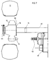
- the frame 46 according to FIGS. 7 to 10 is rigidly connected to a wheel carrier formed by the gear 50 or gear housing.
- the gears 50 according to FIGS. 2 to 6 are connected to the frame 46 so that they can be pivoted vertically via the pivoting device 44, so that the harvesting machine 10 can be kept in a horizontal position within certain limits.
- FIGS. 2 to 10 show various solutions of a frame 46 as they are suitable for making harvesting machines 10 with the same chassis 22 for use on flat terrain and for use on slopes.
- connection means not shown in detail, which can be designed as screw, rivet or welding flanges.
- the frames 46 in FIGS. 2 to 6 are equipped for use on slopes and are therefore provided with the swivel device 44.
- the swivel device 44 establishes a connection between the frame 46 and a drive source 48 on the one hand and the transmission 50 on the other hand and contains a bracket 52, a swivel arm 54 and an adjusting device 56.
- the transmission 50 is direct, immovable and preferably releasably flanged to frame 46; this is shown in FIGS. 7 to 10.
- the wheel 12 can be set in rotation by the drive source 48, which is shown only schematically in the drawing, and can be used both as a front and as a rear wheel.
- the wheel 12 is rotatably mounted in the transmission 50 via an output shaft 65 which merges into a wheel hub.
- the swivel device 44 is designed in such a way that it can be inserted between the gear 50 and the frame 46 and thus makes the harvesting machine 10 intended for the plane suitable for slopes. It is pointed out that it is basically sufficient if only one swivel device 44 is provided for one of the front wheels 12. The size of the possible slope compensation increases, however, if there is a swivel device 44 for each front wheel 12.
- FIGS. 2 to 10 only show the left half of the frame 46 and the parts connected to it, as seen in the direction of travel, including the pivoting device 44 for the left wheel 12.
- the frame 46 is present in this exemplary embodiment and is designed as a single axis; however, this is not mandatory. Rather, if a frame 46 is required at all and the transmission 50 is not directly connected to the chassis 22, one or more brackets or the like can also be provided as the frame 46, which are connected to the relevant points of the chassis 22, in particular flange-mounted.
- the frame 46 of this embodiment is as an axle tube of rectangular cross section formed and connected to the chassis 22 via chassis-side connection means 94. It extends in the lower region of the harvesting machine 10 transversely to its direction of travel and is intended to indirectly accommodate the front wheels 12.
- the chassis-side connection means 94 are shown schematically as a flange, which is also designed as a screw, rivet or welded flange in accordance with the aforementioned flanges provided on the chassis 22.
- the frame 46 is preferably rigidly connected at its end faces or, alternatively, via vertically extending connection means 58, in particular a flange, to the bracket 52. If necessary, a corresponding connection means 60, namely a counter flange, is attached to the console 52.
- the connection can preferably be made by welding.
- the drive source 48 is a conventional multi-speed transmission from which an output shaft 62 projects and which transmits the drive for the front wheels 12.
- this drive source 48 can also be replaced by pressure medium motors.
- the more or less complex gear 50 contained in the gear housing, not shown, is usually referred to as a final drive and advantageously contains a spur gear stage, which causes a speed reduction between the drive source 48 and the front wheel 12.
- a spur gear stage which causes a speed reduction between the drive source 48 and the front wheel 12.
- an input shaft 64 and an output shaft 65 are provided, which mesh with one another via the spur gear stage.
- the use of a chain transmission, a manual transmission or a planetary gear would also be possible.
- the input shaft 64 runs parallel to the output shaft 65, so that the position of the output shaft 65 changes in height when the gear 50 is pivoted about the axis of rotation of the input shaft 64.
- the input shaft 64 and the output shaft 62 preferably run coaxially.
- connection means 60 which are the same for the gearboxes 50 in question and via which the gearbox 50 can be connected to the relevant frame 46.
- the transmission 50 could be designed as a bearing or a hub, in which the wheel 12 is rotatably received and connected to a drive source 48.
- the frame 46, the drive source 48 and the transmission 50 are components which can be used without any changes both on the harvesting machine 10 for the level and on that for the slope. However, in the event that a harvester 10 is to be used exclusively for working on a slope, the flange 58 on the frame 46 can be omitted and the bracket 52 can be welded or screwed directly onto the frame 46.
- the console 52 is formed from thick-walled sheet steel in the manner of a housing which is partially open on its underside and extends substantially parallel to the end face of the frame 46 and preferably at least in partial vertical coverage with a side wall of the chassis 22 an inner wall 66 on the right in the drawing, an outer wall 68, a ceiling 70 and a floor 71.
- the face 52 of the console is open and is partially closed at the bottom 71.
- connection means 58 and the corresponding connection means 60 can be processed in the simplest form as a matching one Surfaces are formed on which the frame 46 and the console 52 connected to each other, for. B. welded.
- connection means 58, 60 can be designed as flanges which are connected to one another by means of screws or rivets.
- the bracket 52 is therefore welded to the frame 46, while it can also be screwed or riveted when using perforated flanges.
- the connection by means of flanges is not only considered for reasons of a possible retrofitting of the frame 46 for use in the plane or on a slope, but can also be chosen for production reasons.
- the ceiling 70 and the floor 71 connect both walls 66, 68 rigidly and torsionally rigid with each other, for. B. by means of a welded joint.
- the outer wall 68 extends parallel to the inner wall 66 and has the same or substantially the same shape as this. There is a free space between the two walls 66, 68 in which the adjusting device 56 can move.
- a bolt 72 which is received and secured in corresponding bores in the walls 66, 68, extends in a front region through the free space and perpendicular to the main plane of extent of the walls 66, 68.
- a bearing 74 formed as a sleeve and having a substantially larger diameter extends through the opposite end region, but protrudes on both sides beyond the walls 66, 68 and is welded to them in order to provide a stable housing design.
- the bearing 74 extends concentrically to the axis of rotation of the output shaft 62 and has two end faces 96. In this embodiment, the bearing 74 is located at the rear of the frame 46 and is at a short distance from it.
- the console 52 consists of a single welded assembly that can be connected to the frame 46 instead of the gear 50.
- the swivel arm 54 consists of a first leg 76 and a second leg 78, which in this exemplary embodiment run at right angles to one another and are non-rotatably connected, namely welded, to one another.
- the two legs 76, 78 can also be connected to one another via a screw or multi-tooth connection which is easily detachable and easy to manufacture.
- each leg 76, 78 can be produced from a suitable material and by means of a suitable method in accordance with the respective stress.
- the first leg 76 can be rotated and surface tempered to provide good sliding properties
- the second leg 78 can be forged as a flat part in a die, thereby achieving high strength.
- the first leg 76 is in the form of a sleeve that extends from the transmission 50 to the output shaft 62 and has an interior space through which a shaft extension (not shown and only required if necessary) can extend, which extends the output shaft 62 to the input shaft 64 connects.
- the outer surface of the first leg 76 which is round cylindrical on the outside, and the inner surface of the bearing 74 are coated in order to obtain suitable sliding and strength properties for the formation of a sliding bearing.
- a separate sliding bushing can also be provided between the first leg 76 and the bearing 74, and finally it makes sense to attach a lubricating device - but all of this is not shown.
- a needle or roller bearing can also be used.
- the first leg 76 is secured against axial displacement outwards, ie to the left with a view of the drawing, by means of a plate 80 which is screwed onto the end face thereof.
- a pressure medium motor (not shown) can also be provided within the first leg 76, which preferably has two speed levels and is placed directly on the input shaft 64.
- two spacer rings 98 are provided for axially positioning the first leg 76 within the bearing 74; however, more or fewer spacer rings 98 can also be used.
- the second leg 78 and with it the gear 50 can be brought further or closer to the console 52 and thus the chassis 22, which opens up the possibility of a track adjustment and the use of further tire sizes.
- the second leg 78 is formed as a plate made of high-quality cast or from a forged part, which has the wheel carrier-side connecting means 58 in the form of a flange in a front end region and a cylindrical opening 82 in another, rear end region.
- the connection means 58 attached to the outside on the wheel carrier side can establish a connection with the connection means 60 designed as a counter flange on the transmission 50 and has a corresponding hole pattern for this purpose in order to enable the use of screws.
- the second leg 78 can overlap the first leg 76 with almost no play, so that both legs 76, 78 can be screwed or welded to one another.
- a stop 84 extends from the inside of the second leg 78 parallel to the first leg 76 and is designed as a pin at the end and can come to rest on a lower edge of the outer wall 68 which can be seen in FIG. 6.
- both the stop 84, which is designed as a pin, and the bolt 72 can be designed as sensor elements with load measuring devices or can be provided with such, which enable the determination of load conditions or the weight of the contents of the grain tank 18, which, however, requires an evaluation device.
- the swivel arm 54 with the gear 50 can pivot in the bearing 74 about the axis of rotation of the bearing 74, which in this exemplary embodiment is coaxial with the output shaft 62, without the coaxiality of the output shaft 62 and the input shaft 64 get lost.
- the actuating device 56 is designed as a linearly acting hydraulic motor which can be acted on from both sides and which comprises a piston 86 and a cylinder 88 and is acted upon by a control or regulating device (not shown).
- the actuating device 56 is actuated in a manner not shown by a hydraulic circuit in which a pressure source and at least one multi-way position valve are provided.
- the multi-way position valve is preferably switched by electromagnets, which receive their control signals from a control loop.
- the control loop contains a well-known pendulum box or mercury scale, which tilts the harvester to the side 10 is detected and forms an output signal therefrom, the aim of which is to keep the harvesting machine 10 horizontal by retracting or extending the adjusting device 56.
- a line guide tube 100 is welded into the console 52, through which hydraulic hoses, not shown, lead to the adjusting device 56, so that they are not exposed to any mechanical stress and are therefore protected.
- the conduit pipe 100 is not shown in Figures 2 to 5 in order to avoid confusion.
- the control loop can also be controlled and bypassed from a manually operated switch, which can initiate an operating and an out-of-operation state.
- a manually operated switch which can initiate an operating and an out-of-operation state.
- the operating state a distinction is made between an idle and a full operating state.
- the two adjusting devices 56 are each extended halfway, so that the harvesting machine 10 is raised in its front area and assumes the correct position with respect to the ground. The adjusting devices 56 remain in this position.
- the two adjusting devices 56 can alternately be fully extended or fully extended in order to raise or lower the harvesting machine 10 on the left or the right side.
- the swivel device 44 is further developed in this embodiment in such a way that by means of the adjustment path of the swivel arm 54 or the gear 50, a signal can also be obtained for the adjustment of a further component, which should also be brought into a position dependent on the slope.
- a further component which should also be brought into a position dependent on the slope.
- a transmitter element 90 is provided, which is also designed as a double and linear hydraulic motor. This transmitter element 90 is pivotally connected at one end (on the cylinder side) via tabs 92 on the frame 46 and on the other end (on the piston rod side) to the plate 80.
- Lines connect the respective pressure chambers of this transmitter member 90 to those of a slave member which is attached to the other pivotally attached component, e.g. B. the cutter. It can be seen that as a result of a pivoting operation of the pivot arm 54 via the first leg 76 and the plate 80, the length of the transmitter element 90 is changed, so that pressure fluid is pressed out of this and through the line to the slave element.
- the articulation point of the encoder member 90 on the plate 80 and the position of the adjusting device 56 relative to the stop 84 and the bolt 72 can be made variable if the spacer rings 98 are used and the axial position of the first leg 76 in the sleeve 74 is changed.
- a cutter height guide with transverse compensation can also be integrated in the hydraulic circuit of the transmitter member 90 and the slave member, which also always leads such an attachment of the harvesting machine 10 to the slope control parallel to the ground in order to avoid the deviation from the parallel due to a sunken wheel, a furrow or to compensate for tire deformation when driving on a slope.
- This cutting height guide could also act directly on the adjusting devices 56.
- Such a slave element can also act on other components controlled depending on the slope, such as guide plates on the sieves or the preparation floor or the position of the sieve box.
- the swivel device 44 is welded directly to the frame 46 via the bracket 52, as previously described, so that an axis results from a uniform welded assembly which connects to the chassis-side connecting means 94 the corresponding connection means can be attached to the chassis 22.
- the harvesting machine 10 can also be constructed as a machine to be operated mainly on the plane, in which the gear 50 is rigidly attached directly to the frame 46 with its connecting means 60 designed as a flange.
- a frame 46 is formed in which all parts connected to the swivel device 44 are missing.
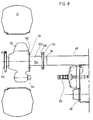
- Such a frame 46 which is preferably designed as an axis, is shown in FIGS. 7 to 10 and has a frame 46 which is overall longer by the width of the swivel device 44 than the frame 46 with swivel device 44, the frame being shown in FIGS. 8 and 10 46 is formed in two parts, and the length corresponding to the pivoting device 44 is bridged by an intermediate piece 102.
- FIGS. 8 and 10 a frame 46 is shown in FIGS. 8 and 10, which essentially corresponds to that according to FIGS. 7 and 9, but which engages on the wheel carrier 50 via an intermediate piece 102.
- This intermediate piece 102 corresponds to the distance between the end of the frame 46 and the connecting means 60 on the gear 50 when the swivel device 44 is used.
- the intermediate piece 102 is composed of a tubular part 104, the wheel carrier-side connecting means 58, which is designed as a plate, and a plate 108, which likewise represents a connecting means, the wheel carrier-side connecting means 58 being connected to the connecting means 60 of the transmission 50 and the plate 108 to a flange, again designed as a connecting means 110 is screwed to the outer end face of the frame 46.
- the same frame 46 is used for the frame 46 designed as an axis for use in the plane and for use on a slope, the distance being bridged either by means of the pivoting device 44 or the intermediate piece 102 becomes.
- the console 52 and the intermediate piece 102 can each be screwed, riveted or welded to the frame 46.
- the frame 46 shown in FIGS. 4, 5, 9 and 10 represents an alternative form of the indirect connection of the transmission 50 to the chassis 22 compared to the frame 46 described at the beginning.
- the transmission 50 could also be connected directly to the chassis 22 if corresponding connection means are provided on this.
- the frame 46 is designed as an axle piece; but it can also be designed as a simple strut, an angle iron, a platform or the like connecting element.
- a separate frame 46 can be provided for each wheel 12; however, a plurality of frames 46 can also be combined to form a common frame, chassis, axle or the like.
- the drive source 48 is not flanged to the chassis 22, but it is indicated that the drive source 48 is located anywhere on the harvester 10 and in many ways, in particular as one mechanical or hydrostatic transmission, which has an output shaft 62, which is connected to the input shaft 64 in a rotationally fixed connection.
- the drive source 48 can, however, also be arranged such that the output and input shafts 62 and 64 do not run coaxially to one another, as shown, but are offset with respect to one another; in this case, a propeller shaft would be used to transmit the drive.
- the drive source 48 could also be flanged directly to the transmission 50 and to the input shaft 64 and the drive transmission could take place by means of a sleeve or another coupling. Any type of connection between the output shaft and the input shaft 62, 64 can be made absolutely rigid, but can also be provided with torsion dampers.
- connection means 58 on the wheel carrier side and the him provided connection means / counter flange 60 releasably connected. Screws, not shown, are used for this in a known manner.
- the pivoting device 44 is designed so that it can be connected to a harvester 10 with a frame 46 according to Figure 9 and thus makes this harvester 10 suitable for slopes.
- each wall 66, 68 On the upper side of the bracket 52 facing the viewer in FIG. 4, a cutout 112 is made in each wall 66, 68, the cross section of which is sufficiently large to be able to accommodate the frame 46.
- the frame 46 it is also possible to place the frame 46 directly on the top of the console 52 and preferably connect it detachably.
- the frame 46 is connected to the console 52 in such a way that the connection means 58 on the wheel carrier side rests on the outside of the outer wall 68 and is connected to the latter by means of the aforementioned screws. Accordingly, the extent of the frame 46 in the direction of the axis of rotation of the wheel 12 remains the same up to here as in the case of a rigidly attached wheel carrier 50.
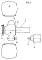
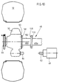
- FIG. 10 shows a frame 46 which essentially corresponds to that shown in FIG. 9. The difference is that, according to FIG. 9, the frame 46 is formed in one piece and extends directly to the transmission 50, while in FIG. 10 it consists of a first and a second part 46a and 46b, the first part 46a with the chassis 22 is connected and also carries a flange 58 on the wheel carrier side.
- the second part 46b is designed as an intermediate piece 102, which is also provided at both ends with a connection means / flange 58 and can be screwed with this to the connection means / counter flange 60 of the transmission 50 and to the wheel carrier-side connection means 58 of the first part 46a.
- the length of the intermediate piece 102 preferably corresponds at least to the width of the bracket 52, that is to say its extension in the direction of the axis of rotation of the wheel 12. It is sometimes also advantageous, however, that To form the intermediate piece 102 longer than the width of the bracket 52, which is explained in more detail in connection with Figure 5.
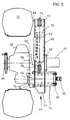
- FIG. 5 shows a swivel device 44 which corresponds to that according to FIG. 4 with the exception of the cutouts 112 - the latter are missing in this embodiment.
- the console 52 of the swivel device 44 is screwed with its inner wall 66 onto the wheel carrier-side connection means 58 of the first part 46a of the frame 46 instead of the intermediate piece 102.
- the arrangement as in Figure 4 is made with the same training options.
- the intermediate piece 102 can also be longer than the width of the bracket 52.
- the intermediate piece 102 including its connecting means / flanges 58, can be as long as the distance between the connecting surface of the second leg 78 on the gear 50 and the connecting surface of the inner wall 66 on the wheel carrier-side connecting means 58 of the first part 46a of the frame 46, so that When the intermediate piece 102 is replaced by the swivel device 44 or vice versa, the position of the wheel 12 relative to the chassis 22 and thus the overall width does not change at all.
- the retrofitting of a harvesting machine 10 suitable for the plane for use on a slope can be carried out by the following method, it being initially assumed that the wheel 12 is attached directly to the chassis 22 by means of the transmission 50.
- the latter method is all the easier to carry out if the frame 46 is shortened by dismantling the intermediate piece 102 of the frame 46.
- the harvesting machine 10 can therefore be easily and even subsequently converted into a slope-compatible harvesting machine 10 by using the suitable combination of frame 46, swivel device 44 and, if necessary, intermediate piece 102.
- the harvesting machine 10 can therefore be easily and subsequently converted into a slope-compatible harvesting machine 10 by - if present - separating the transmission 50 from the frame 46 or its intermediate piece 102, inserting the console 52 in between, screwing the transmission 50 onto the swivel arm 54 and slides into the console 52, connects the actuating device 56 and, if necessary, connects the drive source 48 to the input shaft 64 in a rotationally fixed manner via a shaft extension or a cardan shaft, the latter being omitted if the drive source 48 is placed directly on the input shaft 64.
- a kit for converting the harvesting machine 10 contains the console 52, the swivel arm 54, the adjusting device 56 and, if necessary, a shaft connection.
Landscapes
- Engineering & Computer Science (AREA)
- Mechanical Engineering (AREA)
- Chemical & Material Sciences (AREA)
- Combustion & Propulsion (AREA)
- Transportation (AREA)
- Life Sciences & Earth Sciences (AREA)
- Environmental Sciences (AREA)
- Vehicle Body Suspensions (AREA)
- Harvester Elements (AREA)
- Handcart (AREA)
Abstract
Description
Die Erfindung betrifft eine Erntemaschine mit Seitenhangausgleich.The invention relates to a harvesting machine with side slope compensation.
Maschinen, insbesondere Fahrzeuge, werden grundsätzlich für den Betrieb auf ebenem Boden ausgebildet; demzufolge kann der Einsatz im Gelände, in dem die Aufstandsfläche mehr oder weniger geneigt verläuft, zu nicht unwesentlichen Beeinträchtigungen der Funktion der Maschine führen. Im Falle eines für den Einsatz in der Ebene bestimmten Mähdreschers ist herkömmlich eine Tragvorrichtung vorgesehen, die einen als Achsrohr ausgebildeten Rahmen enthält, an dessen Enden ein Flansch angebracht ist, der der Verbindung mit einem Gegenflansch an einem Endantriebsgehäuse dient. Wird dieser Aufbau belassen, muß bei der Arbeit am Hang entweder mit Kornverlusten gerechnet werden, oder in dem Mähdrescher vorhandene Funktionsgruppen müssen so ausgebildet werden, daß sie eine Hangneigung ausgleichen können.Machines, especially vehicles, are basically designed for operation on level ground; consequently, use in terrain where the footprint is more or less inclined can lead to not insignificant impairments in the functioning of the machine. In the case of a combine harvester intended for use in the plane, a carrying device is conventionally provided which contains a frame designed as an axle tube, at the ends of which a flange is attached, which is used for connection to a counter flange on an end drive housing. If this structure is left, grain losses must either be expected when working on a slope, or functional groups in the combine harvester must be designed so that they can compensate for a slope.
Andererseits sind bereits Tragvorrichtungen vorgeschlagen worden, mit denen eine am Hang bzw. auf sonstigen geneigten Flächen arbeitende Maschine in eine horizontale Stellung gebracht werden kann.On the other hand, carrying devices have already been proposed with which a machine working on a slope or on other inclined surfaces can be brought into a horizontal position.
So zeigt die US-A-37 31 470 einen Mähdrescher mit Endantrieben, die jeweils an einen Schwenkarm angeschlossen und vertikal schwenkbar in einer an einem Rahmen befestigten Konsole gelagert sind. Die Schwenkarme werden mittels eines Hydraulikzylinders um eine horizontale Achse geschwenkt, zu der ein hülsenförmig ausgebildeter Schenkel des Schwenkarms konzentrisch verläuft. Der Endantrieb wird mit dem Schwenkarm vertikal verschwenkt und verstellt somit die Höhe bzw. Neigung des Mähdreschers aufgrund von Signalen, die von einem Neigungssensor ermittelt wurden. In dem Schwenkarm ist zudem ein Kettengetriebe vorgesehen, das den Antrieb von einem Getriebe zu dem Endantrieb überbrückt.For example, US-A-37 31 470 shows a combine harvester with end drives, each of which is connected to a swivel arm and is pivotally mounted in a bracket attached to a frame. The swivel arms are pivoted about a horizontal axis by means of a hydraulic cylinder, to which a sleeve-shaped leg of the swivel arm runs concentrically. The final drive is swiveled vertically with the swivel arm and thus adjusts the height or inclination of the combine harvester on the basis of signals that were determined by an inclination sensor. A chain transmission is also provided in the swivel arm, which bridges the drive from a transmission to the final drive.
Diese Schwenkvorrichtung ist nachteilig, weil der Schwenkarm ein Getriebe enthalten muß, das den Antrieb zwischen der Antriebsquelle und dem Endantrieb überträgt und die Baubreite des Mähdreschers erheblich vergrößert.This swiveling device is disadvantageous because the swivel arm must contain a gearbox which transmits the drive between the drive source and the final drive and considerably increases the overall width of the combine harvester.
Es ist weiterhin bekannt (US-A-3,703,298 und Prospekt: Laverda mietitrebbia autolivellante M 100 AL, Ditta Pietro Laverda, 1a edizione 1971 - FOZ), den gesamten Achskörper eines Mähdreschers in einer quer zur Fahrtrichtung verlaufenden Ebene zu verschwenken und den Antrieb mittels Kardanwellen zu übertragen.It is also known (US-A-3,703,298 and prospectus: Laverda mietitrebbia
Der Aufwand zum Ausrüsten eines Fahrzeugs mit einer derartigen Schwenkvorrichtung ist sehr hoch.The effort to equip a vehicle with such a swivel device is very high.
Die DE-A-1 066 878 und die DE-A-808 183 zeigen jeweils eine Aufhängung eines Rades einer Antriebsachse eines Ackerschleppers, wobei das Rad in einer vertikalen Ebene schwenkbar und darüber hinaus in einer bestimmten Stellung festlegbar ist. Auf diese Weise kann der Ackerschlepper auf der Straße mit einer tiefen Lage des Schwerpunkts und auf dem Feld mit einer hohen Schwerpunktlage gefahren werden, was Beschädigungen von Feldfrüchten durch den Ackerschlepper vermeiden hilft.DE-A-1 066 878 and DE-A-808 183 each show a suspension of a wheel of a drive axle of an agricultural tractor, the wheel being pivotable in a vertical plane and moreover being fixable in a certain position. In this way, the tractor can be driven on the road with a low center of gravity and in the field with a high center of gravity, which helps prevent damage to crops by the tractor.
Es ist weiterhin bekannt, bei Ackerschleppern sowie anderen Fahrzeugen, insbesondere Nutzfahrzeugen, Räder nicht höhenbeweglich, sondern direkt oder über einen Halter, der meist als Endantrieb ausgebildet ist, anzuschließen.It is also known to connect wheels in agricultural tractors and other vehicles, in particular commercial vehicles, not vertically, but directly or via a holder, which is usually designed as a final drive.
Bei derartigen Maschinen kann es sich um jegliche Art von Fahrzeugen, also Landmaschinen, Baufahrzeuge, Forstfahrzeuge, Geländefahrzeuge und dergleichen handeln.Such machines can be any type of vehicle, that is agricultural machinery, construction vehicles, forestry vehicles, off-road vehicles and the like.
Die der Erfindung zugrunde liegende Aufgabe wird darin gesehen, eine Lösung vorzuschlagen, die es ermöglicht, mit relativ wenigen und einfachen Mitteln eine Erntemaschine hangtauglich zu machen, und dabei die Breite so gering wie möglich zu halten.The object on which the invention is based is seen in proposing a solution which makes it possible to make a harvesting machine suitable for slopes with relatively few and simple means, while keeping the width as small as possible.
Diese Aufgabe wird erfindungsgemäß durch die Lehre des Patentanspruchs 1, gelöst, wobei in den weiteren Patentansprüchen Merkmale aufgeführt sind, die die Lösung in vorteilhafter Weise weiterentwickeln.According to the invention, this object is achieved by the teaching of patent claim 1, features being listed in the further patent claims which further develop the solution in an advantageous manner.
Auf diese Weise erstreckt sich die Stellvorrichtung nicht senkrecht, wie dies beim Stand der Technik bekannt ist, sondern im wesentlichen waagrecht und zwar in einer Weise, die eine Anordnung unterhalb des Rahmens oder Fahrgestells zuläßt. Beim Stand der Technik erstrecken sich die Stellvorrichtungen seitlich des Rahmens und nehmen eine beträchtliche Höhe ein, so daß sich die Baubreite erhöht und die für den Straßentransport zulässigen Abmessungen überschreitet.In this way, the adjusting device does not extend vertically, as is known in the prior art, but essentially horizontally, in a manner that allows it to be arranged below the frame or undercarriage. In the prior art, the adjusting devices extend to the side of the frame and take up a considerable height, so that the overall width increases and exceeds the dimensions permitted for road transport.
Das Vorsehen zweier einen Abstand zueinander aufweisender Wellen als Eingangswelle und als Ausgangswelle in dem Getriebe, die zueinander parallel verlaufen, ermöglicht die Nutzung des durch den Hebelarm entstandenen Raums für eine Untersetzungsstufe.The provision of two spaced-apart shafts as input shaft and as output shaft in the transmission, which run parallel to each other, enables the space created by the lever arm to be used for a reduction stage.
Die Konsole kann noch breiter ausgebildet werden, ohne daß sich dadurch die Baubreite der Landmaschine überhaupt oder merklich erhöht, wenn sie wenigstens teilweise in vertikaler Deckung zu einer Seitenwand des Fahrgestells angebracht wird.The console can be made even wider without the overall width of the agricultural machine increasing at all or noticeably if it is attached at least partially in vertical coverage to a side wall of the chassis.
Wenn der zweite Schenkel an das Getriebe, d. h. dessen Getriebegehäuse anflanschbar ist, was vorzugsweise mit Schrauben erfolgt, kann ein vorhandenes Getriebe verwendet werden, das keiner speziellen Anpassung bedarf. Jedenfalls ist das Getriebe und dessen Gehäuse zur Übertragung einer Antriebsbewegung ausgelegt, während der zweite Schenkel keine Antriebselemente benötigt und lediglich die gestellten Festigkeitserfordernisse erfüllen muß.If the second leg connects to the gearbox, i.e. H. whose gear housing can be flanged, which is preferably done with screws, an existing gear can be used that does not require any special adaptation. In any case, the gear and its housing is designed to transmit a drive movement, while the second leg does not require any drive elements and only has to meet the strength requirements.
Eine plattenförmige Ausbildung des zweiten Schenkels führt zu einer weiteren Reduzierung der Baubreite. Eine solche Platte kann auch aus hochfestem Walz- oder Schmiedestahl gebildet werden.A plate-shaped design of the second leg leads to a further reduction in the overall width. Such a plate can also be formed from high-strength rolled or forged steel.
Die Verwendung einer Gleitlagerbüchse zwischen dem ersten Schenkel und dem Lager in der Konsole verringert die Flächenreibung und somit die Reibkräfte, was sich in geringem Wartungsaufwand niederschlägt. Dadurch soll aber keinesfalls die Verwendung von Rollen- oder Kugellagern ausgeschlossen werden.The use of a plain bearing bush between the first leg and the bearing in the console reduces the surface friction and thus the frictional forces, which is reflected in low maintenance. However, this should in no way preclude the use of roller or ball bearings.
Eine Schweißverbindung zwischen der Konsole und dem Rahmen oder dem Fahrgestell stellt eine noch festere Verbindung zwischen diesen her, als z. B. eine Niet- oder Schraubverbindung, was bei den am Hang auftretenden Biege- und Torsionskräften zu mehr Sicherheit führt.A welded connection between the console and the frame or the chassis creates an even stronger connection between these than z. B. a rivet or screw connection, which leads to greater safety in the bending and torsional forces occurring on the slope.
Eine auf die dem zweiten Schenkel abgelegene Seite des ersten Schenkels aufgebrachte Platte hat den Vorteil, daß sie mithilft, den ersten Schenkel gegen eine Axialbewegung in dem Lager zu sichern und daß sie einen Angriffspunkt für ein Geberglied einer abhängigen Steuerung und/oder der Stellvorrichtung bildet.A plate applied to the side of the first leg remote from the second leg has the advantage that it helps to secure the first leg against axial movement in the bearing and that it forms a point of attack for an encoder element of a dependent control and / or the actuating device.
Das Vorhandensein eines Anschlags an dem Schwenkarm, insbesondere an dessen zweiten Schenkel, stellt ein Sicherheitsmerkmal dar, weil dadurch beim Ausfall der Stellvorrichtung vermieden werden kann, daß der Radträger in eine Stellung gelangt, in der das Fahrzeug Schaden nimmt. Dieser Anschlag kann an der Konsole oder an dem Tragteil zur Anlage kommen.The presence of a stop on the swivel arm, in particular on its second leg, represents a safety feature because, if the adjusting device fails, this can prevent the wheel carrier from reaching a position in which the vehicle is damaged. This stop can come to rest on the console or on the supporting part.
Eine Teileoptimierung tritt ein, wenn der Anschlag, der als Zapfen ausgebildet sein kann, zugleich einen Angriffspunkt für die Stellvorrichtung bildet.Part optimization occurs when the stop, which can be designed as a pin, also forms a point of attack for the adjusting device.
Die Ausbildung des ersten Schenkels als eine Büchse, die einen Durchtritt für eine zu der Eingangswelle führende Welle bildet, wahrt weiterhin die Trennung zwischen den Komponenten zur Übertragung der Antriebsbewegung von denen für die Schwenkbewegung.The formation of the first leg as a sleeve, which forms a passage for a shaft leading to the input shaft, also maintains the separation between the components for transmitting the drive movement from those for the swivel movement.
Die Verwendung gleicher oder kompatibler Anschlußmittel für eine Erntemaschine mit oder ohne Hangausgleich spart Teile und eröffnet die Möglichkeit, eine Basismaschine nachträglich in eine Erntemaschine mit oder ohne Hangausgleich umzurüsten.Using the same or compatible connection means for a harvesting machine with or without slope compensation saves parts and opens up the possibility of retrofitting a basic machine into a harvesting machine with or without slope compensation.
Wenn die Achse der Ausgangswelle einer Antriebsquelle, die einer Eingangswelle des Getriebes und die eines Lagers zur Aufnahme des Schwenkarms koaxial zueinander verlaufen, kann die Schwenkbewegung um die beiden Wellen erfolgen, ohne daß es zu einer Änderung der relativen Lage zwischen diesen kommt; die Ausrichtung der Eingangswelle zu der Abtriebswelle bleibt erhalten; diese verlaufen konzentrisch zu der Schwenkachse des Getriebes.If the axis of the output shaft of a drive source, that of an input shaft of the transmission and that of a bearing for receiving the swivel arm are coaxial with one another, the swiveling movement can take place around the two shafts without changing the relative position between them; the Alignment of the input shaft with the output shaft is retained; these run concentrically to the pivot axis of the gear.
Die getrennte Ausbildung und anschließende formschlüssige und vorzugsweise lösbare Verbindung beider Schenkel des Schwenkarms ist fertigungstechnisch günstig, weil der eine Schenkel eine hohe Festigkeit und der andere Schenkel eine gute Gleiteigenschaft in dem Lager aufweisen muß, was mit einem aus gleichem Material hergestellten einteiligen Schwenkarm mitunter schwer zu erreichen ist. Der Schwenkarm kann festigkeitsmäßig optimal ausgebildet werden, wenn seine Schenkel für die jeweilige Beanspruchung aus geeignetem Material gebildet und anschließend vorzugsweise mittels Schweißen oder anderer, lösbarer Verbindungsarten zusammengefügt werden. Auf diese Weise ist es z.B. möglich, den mit dem Radträger verschraubten einen Schenkel aus einem hochfesten Schmiedeteil zu bilden, während ein senkrecht dazu verlaufender und in ein drehbares Lager eingesetzter Schenkel mit einer hohen Oberflächengüte versehen wird.The separate training and subsequent positive and preferably releasable connection of both legs of the swivel arm is favorable in terms of production technology, because one leg has a high strength and the other leg must have good sliding properties in the bearing, which can be difficult with a one-piece swivel arm made of the same material to achieve. The swivel arm can be optimally designed in terms of strength if its legs are made of a suitable material for the respective stress and are then preferably joined together by welding or other detachable connection types. In this way it is e.g. possible to form a leg bolted to the wheel carrier from a high-strength forged part, while a leg running perpendicular to it and inserted into a rotatable bearing is provided with a high surface quality.
Wird an den Schwenkarm ein Geberglied angeschlossen, das dessen Stellung ermittelt und daraus ein Ausgangssignal bildet, kann mit diesem ein Nehmerglied gesteuert werden, das bei einem Mähdrescher z. B. dessen Erntebergungsvorrichtung in einer Lage parallel zu dem Boden führt. Das Geberglied kann sowohl hydraulisch, wie auch mechanisch oder elektrisch wirkend ausgebildet sein. Die hydraulische Ausbildung ist dort von sehr großem Nutzen, wo hohe Stellkräfte übertragen werden müssen.If a transmitter link is connected to the swivel arm, which determines its position and forms an output signal therefrom, this can be used to control a slave link, which in a combine harvester z. B. whose harvesting device leads in a position parallel to the ground. The transmitter element can be designed to act hydraulically as well as mechanically or electrically. Hydraulic training is very useful where high actuating forces have to be transferred.
Eine optimale und alle Betriebszustände erfassende Regelung der Landmaschine ist möglich, wenn auf die Regeleinrichtung der Stellvorrichtungen selbst oder auf eine an diese angeschlossene Steuerung der Querneigung eines an das vordere Ende der Landmaschine angebauten Vorsatzes zusätzlich ein Vorsatz-Querausgleichssystem wirkt, das zum Ziel hat, den Vorsatz zusätzlich und unabhängig von einer Hangneigung stets parallel zu dem Boden zu führen.An optimal control of the agricultural machine, which covers all operating states, is possible if an additional cross-compensation system acts on the control device of the adjusting devices themselves or on a control of the transverse inclination of a front attachment attached to the front end of the agricultural machine In addition, regardless of a slope, always use the header to run parallel to the ground.
Die Verwendung eines doppeltwirkenden linearen Hydraulikmotors als Geberglied für eine nachrangige Steuerung oder Regelung der Querneigung eines Erntevorsatzes sorgt für eine sichere Übertragung der Stellbewegung in beiden Richtungen.The use of a double-acting linear hydraulic motor as a transmitter element for a subordinate control or regulation of the cross slope of a header ensures a reliable transmission of the actuating movement in both directions.
Die Verwendung wenigstens eines Distanzrings zwischen dem ersten Schenkel und dem Lager, der wahlweise zwischen der einen oder der anderen Stirnseite des als Hülse ausgebildeten Lagers und dem ersten Schenkel eingefügt werden kann, ermöglicht es, den ersten Schenkel dauerhaft in dem Lager in unterschiedlichen axialen Stellungen zu halten und somit die Spurbreite des Fahrzeug bzw. der Landmaschine zu variieren.The use of at least one spacer ring between the first leg and the bearing, which can optionally be inserted between one or the other end face of the bearing designed as a sleeve and the first leg, enables the first leg to be permanently held in the bearing in different axial positions hold and thus to vary the track width of the vehicle or the agricultural machine.
Je nachdem, ob es auf die Einhaltung einer bestimmten Fahrzeugbreite im Bereich der Räder ankommt oder nicht, kann das Fahrgestell bzw. der Tragteil an der inneren oder der äußeren Wand einer doppelwandigen Konsole der Schwenkvorrichtung angeschlossen werden.Depending on whether it is important to maintain a certain vehicle width in the area of the wheels or not, the chassis or the supporting part can be connected to the inner or outer wall of a double-walled bracket of the swivel device.
Ist ein Anschluß an der äußeren Wand vorgesehen, kann durch Ausschnitte in den oberen Bereichen der Wände der Tragteil in die Schwenkvorrichtung mit einbezogen werden, so daß sich auch die Bauhöhe nicht verändert.If a connection is provided on the outer wall, cutouts in the upper areas of the walls allow the support part to be included in the swivel device, so that the overall height does not change.
Der Antrieb des Radträgers kann anstatt über eine Welle von einem mechanischen Getriebe aus auch direkt mittels eines Druckmittelmotors erfolgen, der umso geschützter ist, wenn er innerhalb des ersten Schenkels untergebracht wird. Die Ausbildung als zwei- oder mehrstufiger Druckmittelmotor führt zu einem großen Geschwindigkeitsbereich.Instead of a shaft, the wheel carrier can be driven directly from a mechanical transmission by means of a pressure medium motor, which is all the more protected when it is accommodated within the first leg. Training as a two- or multi-stage pressure medium motor leads to a large speed range.
Wird ein die Stellvorrichtung abstützender Bolzen als Sensorglied, z. B. als Last- oder Druckbolzen ausgebildet, kann über die empfangenen Signale, z. B. ein Überlastzustand oder eine Gewichtszunahme z. B. aufgrund der Korntankbefüllung ermittelt werden.If the actuator supporting bolt as a sensor element, for. B. designed as a load or pressure bolt, can be received via the received signals, for. B. an overload condition or weight gain z. B. can be determined based on the grain tank filling.
Eine minimierte Beanspruchung der Stellvorrichtung in einem Außerbetriebszustand wird erreicht, wenn die Kolben ganz in die Zylinder eingefahren und somit drucklos sind und zwischen einem Ruhe- und einem Voll-Betriebszustand unterschieden wird, wobei nur in dem Vollbetriebszustand eine Regelung des Schwenkmaßes des Radträgers erfolgt.A minimized stress on the actuating device in an inoperative state is achieved when the pistons are fully in the The cylinders are retracted and are therefore depressurized and a distinction is made between an idle and a full operating state, the pivoting dimension of the wheel carrier being regulated only in the full operating state.
Die beiden aus Kolben und Zylinder bestehenden Stellvorrichtungen können auf vorteilhafte Weise auch so auf manuelle Weise gesteuert werden, daß sie ganz ausfahren und somit die Landmaschine über ein für den Betrieb normalerweise geeignetes Maß anheben. Das Anheben kann Vorteile bei der Verladung, bei der Wartung, beim An- und Abkuppeln eines Vorsatzes und ähnlicher Vorgänge entwickeln. Außerdem kann auf diese Weise die Erntemaschine auch in Längsrichtung gegenüber dem Hang verstellt werden.The two actuators, consisting of pistons and cylinders, can advantageously also be controlled in a manual manner in such a way that they extend completely and thus raise the agricultural machine to an extent that is normally suitable for operation. Lifting can develop benefits in loading, maintenance, attaching and detaching a header, and similar operations. In addition, the harvesting machine can also be adjusted in the longitudinal direction in relation to the slope.
Die Anordnung der Konsole(n) unterhalb der Seitenwände des Fahrgestells oder Rahmens der Erntemaschine bzw. zwischen diesen Seitenwänden hat den großen Vorteil, daß sich die Breite der Konsolen nicht zu der Maschinenbreite hinzuaddiert, wodurch erneut eine geringe Baubreite erreicht wird.The arrangement of the console (s) below the side walls of the chassis or frame of the harvesting machine or between these side walls has the great advantage that the width of the consoles is not added to the machine width, which again results in a small overall width.
In der Zeichnung sind mehrere nachfolgend näher beschriebene Ausführungsbeispiele der Erfindung dargestellt. Es zeigt:
- Fig. 1
- eine Erntemaschine in Seitenansicht,
- Fig. 2
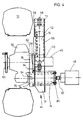
- einen Rahmen mit einer Schwenkvorrichtung in Draufsicht,
- Fig. 3
- einen Rahmen anderer Bauart mit einer Schwenkvorrichtung in Draufsicht,
- Fig. 4
- einen Rahmen mit einer geänderten Schwenkvorrichtung in Draufsicht,
- Fig. 5
- einen Rahmen mit einer in anderer Weise angebrachten Schwenkvorrichtung in Draufsicht,
- Fig. 6
- die Schwenkvorrichtung nach den Figuren 2 bis 5 in Seitenansicht,
- Fig. 7
- einen Rahmen ohne Schwenkvorrichtung in Draufsicht,
- Fig. 8
- einen Rahmen ohne Schwenkvorrichtung, aber mit einem Zwischenstück in Draufsicht,
- Fig. 9
- einen Rahmen ohne Schwenkvorrichtung in Draufsicht und
- Fig. 10
- einen Rahmen ohne Schwenkvorrichtung, aber mit einem Zwischenstück in Draufsicht,
- Fig. 1
- a harvesting machine in side view,
- Fig. 2
- a frame with a swivel device in plan view,
- Fig. 3
- a frame of another type with a swivel device in plan view,
- Fig. 4
- a frame with a modified swivel device in plan view,
- Fig. 5
- a frame with a swivel device attached in a different way in plan view,
- Fig. 6
- the swivel device according to Figures 2 to 5 in side view,
- Fig. 7
- a frame without swivel device in plan view,
- Fig. 8
- a frame without swivel device, but with an intermediate piece in plan view,
- Fig. 9
- a frame without pivoting device in plan view and
- Fig. 10
- a frame without swivel device, but with an intermediate piece in plan view,
Eine in Figur 1 gezeigte Erntemaschine 10 in der Form eines Mähdreschers ist auf vorderen angetriebenen und rückwärtigen lenkbaren Rädern 12 bzw. 14 getragen und weist eine Fahrerkabine 16 auf, von der aus sie von einem Fahrer bedient werden kann. Anstatt eines Mähdreschers könnte ebenso jede andere Art von Land- Bau- und Forstmaschine oder sonstigem Fahrzeug, insbesondere ein Traubenvollernter, ein Hochrad-Ackerschlepper, eine Mähmaschine, ein Geländefahrzeug, ein Freizeitfahrzeug, ein Feldhäcksler, ein Baumwollpflücker, ein Ackerschlepper, ein Bagger, ein Baumfäller und ein Lastwagen oder dergleichen für die Anwendung der Erfindung dienen. An die Fahrerkabine 16 schließt sich rückwärtig ein Korntank 18 an, der in ihn abgegebenes Gut über ein Entleerrohr 20 nach außen abgeben kann. Der Korntank 18 lagert auf einem Fahrgestell 22, das ein Chassis, ein Fahrzeugtragrahmen, ein Unterbau oder dergleichen sein kann und an das die vorderen Räder 12 in diesem Ausführungsbeispiel über einen in vielfältiger Weise ausbildbaren Rahmen 46 und jeweils ein Getriebe 50 dreh- und antreibbar angeschlossen sind; die Räder 12 können aber auch direkt an das Fahrgestell 22 angeschlossen sein. In dem Fahrgestell 22 wird zugeführtes Gut auf dem Weg über eine Dreschtrommel 24, einen Dreschkorb 26 und eine Wendetrommel 28 in seine großen und kleinen Bestandteile zerlegt. Auf daran anschließenden Schüttlern 30, sowie auf einem Vorbereitungsboden 32 und Sieben 34 wird eine weitere Trennung des geernteten Guts durchgeführt, wobei schließlich der ausgedroschene Gutanteil in den Korntank 18 gefördert wird, die großen Erntegutteile über die Schüttler 30 auf den Boden abgelegt werden und leichte Bestandteile mittels eines Gebläses 36 von den Sieben 34 ebenfalls auf den Boden geblasen werden. Auf dem Boden liegendes oder stehendes Gut wird über einen Schrägförderer 38 und eine Steinfangmulde 40 der Dreschtrommel 24 zugeführt, nachdem es von einem nicht gezeigten und als Erntegutbergungsvorrichtung ausgebildeten Vorsatz vom Boden aufgenommen worden ist.A harvesting
Die Qualität und die Quantität der Trennung des Ernteguts auf den Schüttlern 30, dem Vorbereitungsboden 32 und den Sieben 34 sind am besten, wenn sich die Erntemaschine 10 auf einer waagrechten Aufstandsfläche befindet.The quality and quantity of the separation of the crop on the
Für den Einsatz in Hanglagen ist daher eine erfindungsgemäße Schwenkvorrichtung 44 vorgesehen, die die Erntemaschine 10 innerhalb bestimmter Grenzen in einer waagrechten Lage hält.A
Für den Einsatz in ebenem Gelände ist der Rahmen 46 gemäß den Figuren 7 bis 10 starr mit einem von dem Getriebe 50 bzw. Getriebegehäuse gebildeten Radträger verbunden. Für den dauerhaften oder teilweisen Einsatz der Erntemaschine 10 in Hanglagen sind die Getriebe 50 gemäß den Figuren 2 bis 6 über die Schwenkvorrichtung 44 vertikal schwenkbar an den Rahmen 46 angeschlossen, so daß die Erntemaschine 10 innerhalb bestimmter Grenzen in einer waagrechten Lage gehalten werden kann.For use in flat terrain, the
In den Figuren 2 bis 10 sind verschiedene Lösungen eines Rahmens 46 gezeigt, wie sie geeignet sind, aus Erntemaschinen 10 mit gleichem Fahrgestell 22 solche für den Einsatz auf ebenem Gelände und solche für den Einsatz in Hanglagen zu machen. Zu ihrer Verbindung mit dem Fahrgestell 22 ist der Rahmen 46 mit nicht detailliert gezeigten Anschlußmitteln versehen, die als Schraub-, Niet- oder Schweißflansche ausgebildet sein können.FIGS. 2 to 10 show various solutions of a
Die Rahmen 46 in den Figuren 2 bis 6 sind für den Einsatz in Hanglagen gerüstet und deshalb mit der Schwenkvorrichtung 44 versehen.The
Die Schwenkvorrichtung 44 stellt eine Verbindung zwischen dem Rahmen 46 und einer Antriebsquelle 48 einerseits und dem Getriebe 50 andererseits her und enthält eine Konsole 52, einen Schwenkarm 54 und eine Stellvorrichtung 56. Bei Erntemaschinen 10 ohne die Schwenkvorrichtung 44 ist das Getriebe 50 direkt, unbeweglich und vorzugsweise lösbar an den Rahmen 46 angeflanscht; dies wird in den Figuren 7 bis 10 dargestellt.The
Das Rad 12 kann durch die Antriebsquelle 48, die in der Zeichnung nur schematisch dargestellt ist, in Drehung versetzt werden und kann sowohl als Vorder- wie auch als Hinterrad eingesetzt werden. Das Rad 12 ist über eine in eine Radnabe übergehende Ausgangswelle 65 in dem Getriebe 50 drehbar gelagert.The
Die Schwenkvorrichtung 44 ist derart ausgebildet, daß sie zwischen das Getriebe 50 und den Rahmen 46 eingefügt werden kann und somit die für die Ebene vorgesehene Erntemaschine 10 hangtauglich macht. Es wird darauf hingewiesen, daß es grundsätzlich ausreicht, wenn nur eine Schwenkvorrichtung 44 für eines der vorderen Räder 12 vorgesehen ist. Die Größe des möglichen Hangausgleichs erhöht sich jedoch, wenn für jedes vordere Rad 12 eine Schwenkvorrichtung 44 besteht. Die Figuren 2 bis 10 zeigen nur die in Fahrtrichtung gesehen linke Hälfte des Rahmens 46 und der an ihn angeschlossenen Teile, einschließlich der Schwenkvorrichtung 44 für das linke Rad 12.The
Der Rahmen 46 ist in diesem Ausführungsbeispiel vorhanden und als eine einzige Achse ausgebildet; dies ist jedoch nicht zwingend. Vielmehr kann - sofern ein Rahmen 46 überhaupt erforderlich und das Getriebe 50 nicht direkt an das Fahrgestell 22 angeschlossen ist - als Rahmen 46 auch eine oder mehrere Konsolen oder dergleichen vorgesehen sein, die an die betreffenden Stellen des Fahrgestells 22 angeschlossen, insbesondere angeflanscht werden. Der Rahmen 46 dieses Ausführungsbeispiels ist als ein Achsrohr von rechteckigem Querschnitt ausgebildet und mit dem Fahrgestell 22 über fahrgestellseitige Anschlußmittel 94 verbunden. Er erstreckt sich im unteren Bereich der Erntemaschine 10 quer zu dessen Fahrtrichtung und ist dazu bestimmt, die vorderen Räder 12 mittelbar drehbar aufzunehmen. Die fahrgestellseitigen Anschlußmittel 94 sind schematisch als Flansch dargestellt, der entsprechend den an dem Fahrgestell 22 vorgesehenen zuvor erwähnten Flanschen ebenfalls als Schraub-, Niet- oder Schweißflansch ausgebildet ist. Der Rahmen 46 ist vorzugsweise an seinen Endflächen starr oder alternativ über sich vertikal erstreckende Anschlußmittel 58, insbesondere einen Flansch mit der Konsole 52 verbunden. Erforderlichenfalls ist an der Konsole 52 ein korrespondierendes Anschlußmittel 60, nämlich ein Gegenflansch angebracht. Die Verbindung kann vorzugsweise mittels Schweißen hergestellt werden.The
Bei der Antriebsquelle 48 handelt es sich um ein herkömmliches Mehrganggetriebe, aus dem eine Abtriebswelle 62 ragt und die den Antrieb für die vorderen Räder 12 überträgt. Diese Antriebsquelle 48 kann allerdings auch durch Druckmittelmotoren ersetzt werden.The
Das in dem Getriebegehäuse enthaltene, nicht gezeigte mehr oder weniger aufwendige Getriebe 50 wird üblicherweise als Endantrieb bezeichnet und enthält vorteilhafterweise eine Stirnradstufe, die eine Drehzahluntersetzung zwischen der Antriebsquelle 48 und dem vorderen Rad 12 bewirkt. Hierzu sind eine Eingangswelle 64 und eine Ausgangswelle 65 vorgesehen, die über die Stirnradstufe miteinander kämmen. Andererseits wäre auch die Verwendung eines Kettengetriebes, eines Schaltgetriebes oder eines Planetengetriebes möglich. Jedenfalls verläuft die Eingangswelle 64 parallelachsig zu der Ausgangswelle 65, so daß sich die Lage der Ausgangswelle 65 in der Höhe verändert, wenn man das Getriebe 50 um die Drehachse der Eingangswelle 64 schwenkt. Die Eingangswelle 64 und die Abtriebswelle 62 verlaufen vorzugsweise koaxial. Je nach dem in dem Getriebegehäuse enthaltenen Getriebe 50 und dessen festigkeitsmäßiger Ausbildung kann dieses unterschiedlich ausgebildet sein und gegebenenfalls unterschiedliche Lochbilder für nicht gezeigte Gewindebohrungen aufweisen. Die Gewindebohrungen können sowohl in einem zusammenhängenden Flansch wie auch in eigenständigen Zapfen, die vorzugsweise mit Gewindebohrungen für Dehnschrauben versehen sind, enthalten sein. Ein derartiger Flansch, derartige Zapfen oder dergleichen werden allgemein als Anschlußmittel 60 bezeichnet, die bei den in Betracht kommenden Getrieben 50 gleich sind und über die das Getriebe 50 an den betreffenden Rahmen 46 angeschlossen werden kann.The more or less
Alternativ hierzu könnte das Getriebe 50 in seiner einfachsten Form als ein Lager oder eine Nabe ausgebildet sein, in der das Rad 12 drehbar und mit einer Antriebsquelle 48 verbunden aufgenommen ist.Alternatively, in its simplest form, the
Bei dem Rahmen 46, der Antriebsquelle 48 und dem Getriebe 50 handelt es sich um Komponenten, die ohne jegliche Änderung sowohl an der Erntemaschine 10 für die Ebene als auch an dem für den Hang verwendet werden können. Allerdings kann in dem Fall, daß eine Erntemaschine 10 ausschließlich für die Arbeit am Hang eingesetzt werden soll, der Flansch 58 an dem Rahmen 46 entfallen und die Konsole 52 direkt an den Rahmen 46 angeschweißt oder angeschraubt werden.The
Die Konsole 52 wird in diesem speziellen Ausführungsbeispiel aus dickwandigem Stahlblech in der Art eines an seiner Unterseite teilweise offenen Gehäuses gebildet und erstreckt sich im wesentlichen parallel zu der Stirnseite des Rahmens 46 und vorzugsweise wenigstens in teilweiser vertikaler Deckung mit einer Seitenwand des Fahrgestells 22. Erwähnt seien eine innere, in der Zeichnung rechts gelegene Wand 66, eine äußere Wand 68, eine Decke 70 und ein Boden 71.In this special exemplary embodiment, the
Stirnseitig ist die Konsole 52 offen, und am Boden 71 ist sie teilweise geschlossen.The
Die innere Wand 66 ist über eine plane Fläche oder einen Flansch starr an den Rahmen 46 angeschweißt oder angeschraubt. Das Anschlußmittel 58 und das korrespondierende Anschlußmittel 60 können in der einfachsten Form als zusammenpassende bearbeitete Flächen ausgebildet sein, an denen der Rahmen 46 und die Konsole 52 miteinander verbunden, z. B. verschweißt werden. In einer weiterentwickelten Ausführungsform können die Anschlußmittel 58, 60 als Flansche ausgebildet sein, die mittels Schrauben oder Nieten miteinander verbunden werden.The
In der einfachsten Form wird also die Konsole 52 an den Rahmen 46 angeschweißt, während sie bei der Benutzung von Loch-Flanschen auch angeschraubt oder angenietet werden kann. Die Verbindung mittels Flanschen kommt nicht nur aus Gründen einer möglichen Umrüstung des Rahmens 46 für den Einsatz in der Ebene bzw. am Hang in Betracht, sondern kann auch aus Fertigungsgründen so gewählt werden.In its simplest form, the
Die Decke 70 und der Boden 71 verbinden beide Wände 66, 68 starr und drehsteif miteinander, z. B. mittels einer Schweißverbindung.The
Die äußere Wand 68 erstreckt sich parallel zu der inneren Wand 66 und weist die gleiche oder im wesentlichen die gleiche Form auf wie diese. Zwischen beiden Wänden 66, 68 befindet sich ein Freiraum, in dem sich die Stellvorrichtung 56 bewegen kann. Durch den Freiraum und senkrecht zu der Haupterstreckungsebene der Wände 66, 68 erstreckt sich in einem vorderen Bereich ein Bolzen 72, der in entsprechende Bohrungen in den Wänden 66, 68 aufgenommen und gesichert ist. Durch den gegenüberliegenden Endbereich erstreckt sich analog ein als eine Hülse ausgebildetes Lager 74 von wesentlich größerem Durchmesser, das jedoch beiderseits über die Wände 66, 68 übersteht und mit diesen verschweißt ist, um eine stabile Gehäuseausführung zu erbringen. Das Lager 74 erstreckt sich konzentrisch zu der Drehachse der Abtriebswelle 62 und weist zwei Stirnflächen 96 auf. Das Lager 74 befindet sich bei diesem Ausführungsbeispiel rückwärtig des Rahmens 46 und weist zu diesem einen geringen Abstand auf.The
Nach alledem besteht die Konsole 52 aus einem einzigen Schweißzusammenbau, der anstelle des Getriebes 50 an den Rahmen 46 angeschlossen werden kann.After all, the
Der Schwenkarm 54 besteht aus einem ersten Schenkel 76 und einem zweiten Schenkel 78, die in diesem Ausführungsbeispiel rechtwinklig zueinander verlaufen und drehfest miteinander verbunden, nämlich verschweißt, sind. In einer weiterentwickelten Ausführungsform können die beiden Schenkel 76, 78 auch über eine Schraub- oder Vielzahn-Verbindung miteinander verbunden sein, die leicht lösbar und leicht herstellbar ist. Auf diese Weise kann jeder Schenkel 76, 78 der jeweiligen Beanspruchung entsprechend aus geeignetem Material und mittels eines geeigneten Verfahrens hergestellt werden. Beispielsweise kann der erste Schenkel 76 gedreht und an der Oberfläche hochvergütet werden, um gute Gleiteigenschaften aufzuweisen, und der zweite Schenkel 78 kann als flacher Teil in einem Gesenk geschmiedet werden, wodurch eine hohe Festigkeit erreicht wird.The
Der erste Schenkel 76 weist die Form einer Büchse auf, die sich von dem Getriebe 50 zu der Abtriebswelle 62 erstreckt und einen Innenraum aufweist, durch den sich bequem eine nicht gezeigte und nur im Bedarfsfall erforderliche Wellenverlängerung erstrecken kann, die die Abtriebswelle 62 mit der Eingangswelle 64 verbindet. Die äußere Oberfläche des ersten, außen rundzylindrischen, Schenkels 76 sowie die innere Oberfläche des Lagers 74 sind vergütet, um geeignete Gleit- und Festigkeitseigenschaften zur Bildung eines Gleitlagers zu erhalten. Gleichermaßen kann zwischen dem ersten Schenkel 76 und dem Lager 74 auch eine separate Gleitbüchse vorgesehen werden, und schließlich ist es sinnvoll, eine Schmiervorrichtung anzubringen - all dies ist jedoch nicht gezeigt. Anstelle der Gleitlagerung kann auch ein Nadel- oder Rollenlager Verwendung finden. Der erste Schenkel 76 ist gegen eine axiale Verschiebung nach außen, d. h. mit Blick auf die Zeichnung nach links, mittels einer Platte 80 gesichert, die stirnseitig auf ihn aufgeschraubt ist. Wie bereits erwähnt, kann innerhalb des ersten Schenkels 76 anstatt der Verbindung mit der Antriebsquelle 48 über die Abtriebswelle 62 auch ein nicht gezeigter Druckmittelmotor vorgesehen werden, der vorzugsweise zwei Geschwindigkeitsstufen aufweist und direkt auf die Eingangswelle 64 aufgesetzt ist.The
Zur axialen Positionierung des ersten Schenkels 76 innerhalb des Lagers 74 sind in diesem Ausführungsbeispiel zwei Distanzringe 98 vorgesehen; es sind jedoch auch mehr oder weniger Distanzringe 98 verwendbar. Gemäß dem Ausführungsbeispiel nach Figur 2 befindet sich ein Distanzring 98 zwischen der in der Zeichnung linken Stirnfläche 96 des Lagers 74 und der Verbindungsstelle zwischen beiden Schenkeln 76, 78 und ein weiterer Distanzring 98 zwischen der in der Zeichnung rechts gelegenen Stirnfläche 96 und der Platte 80. Auf diese Weise kann der zweite Schenkel 78 und mit diesem das Getriebe 50 weiter oder näher an die Konsole 52 und somit das Fahrgestell 22 herangebracht werden, was die Möglichkeit einer Spurverstellung und der Verwendung weiterer Reifengrößen eröffnet.In this exemplary embodiment, two spacer rings 98 are provided for axially positioning the
Der zweite Schenkel 78 ist als eine Platte aus hochwertigem Guß oder aus einem Schmiedeteil gebildet, die das als Flansch ausgebildete radträgerseitige Anschlußmittel 58 in einem vorderen Endbereich und eine zylindrische Öffnung 82 in einem anderen, rückwärtigen Endbereich aufweist. Das an der Außenseite angebrachte radträgerseitige Anschlußmittel 58 kann eine Verbindung mit dem als Gegenflansch ausgebildeten Anschlußmittel 60 an dem Getriebe 50 eingehen und weist hierzu ein entsprechendes Lochbild auf, um den Einsatz von Schrauben zu ermöglichen. Mittels der Öffnung 82 kann der zweite Schenkel 78 den ersten Schenkel 76 nahezu ohne Spiel übergreifen, so daß beide Schenkel 76, 78 miteinander verschraubt oder verschweißt werden können. Schließlich erstreckt sich von der Innenseite des zweiten Schenkels 78 parallelachsig zu dem ersten Schenkel 76 ein Anschlag 84, der endseitig als Zapfen ausgebildet ist und an einer in Figur 6 erkennbaren Unterkante der äußeren Wand 68 zur Anlage kommen kann.The
Sowohl der als Zapfen ausgebildete Anschlag 84 wie auch der Bolzen 72 können in einer erweiterten Ausführungsform als Sensorglieder mit Lastmeßvorrichtungen ausgebildet oder mit solchen versehen sein, die die Ermittlung von Lastzuständen oder des Gewichts des Inhalts des Korntanks 18 ermöglichen, wozu allerdings eine Auswertungseinrichtung erforderlich ist.In an extended embodiment, both the
Es zeigt sich somit, daß der Schwenkarm 54 mit dem Getriebe 50 um die Drehachse des Lagers 74, die in diesem Ausführungsbeispiel mit der der Abtriebswelle 62 koaxial ist, in dem Lager 74 schwenken kann, ohne daß die Koaxialität der Abtriebswelle 62 und der Eingangswelle 64 verloren geht.It can thus be seen that the
Die Stellvorrichtung 56 ist in diesem Ausführungsbeispiel als ein linear wirkender, doppelseitig beaufschlagbarer Hydraulikmotor ausgebildet, der einen Kolben 86 und einen Zylinder 88 umfaßt und von einer nicht gezeigten Steuer- oder Regelvorrichtung beaufschlagt wird.In this exemplary embodiment, the
Während das zylinderseitige Ende der Stellvorrichtung 56 auf dem Bolzen 72 schwenkbar gelagert ist, greift dessen kolbenstangenseitiges Ende an dem Anschlag 84 auf dessen als Zapfen ausgebildeten Endbereich schwenkbar an. In einer eingefahrenen Stellung liegt der Anschlag 84 an der Unterkante der äußeren Wand 68 an, und die Stellvorrichtung 56 ragt teilweise nach unten aus der Konsole 52 heraus. In einer ausgefahrenen Stellung der Stellvorrichtung 56 bewegt sich sowohl die Stellvorrichtung 56 als auch das Getriebe 50 nach unten aus der Konsole 52 heraus bzw. über diese hinaus. Infolge einer Aktivierung der Stellvorrichtung 56 wird demnach das Getriebe 50 mit dem Schwenkarm 54 in dem Lager 74 gedreht. Es ist mit Blick auf Figur 6 ersichtlich, daß das Getriebe 50 entgegen dem Uhrzeigerdrehsinn um die Längsmittenachse des Lagers 74 schwenkt, sobald die Stellvorrichtung 56 ausgefahren wird. Diese Schwenkbewegung bewirkt, daß sich der Abstand zwischen dem Rahmen 46 und der Aufstandsfläche des Rades 12 verändert und das Fahrgestell 22, also die gesamte Erntemaschine 10 zumindest auf einer Seite angehoben wird.While the cylinder-side end of the adjusting
Die Stellvorrichtung 56 wird auf nicht gezeigte Weise von einem Hydraulikschaltkreis betätigt, in dem eine Druckquelle und wenigstens ein Mehrwege-Stellungsventil vorgesehen sind. Das Mehrwege-Stellungsventil wird vorzugsweise von Elektromagneten geschaltet, die ihre Steuersignale von einem Regelkreis erhalten. Der Regelkreis enthält eine bekannte Pendelbox oder Quecksilberwaage, die eine seitliche Neigung der Erntemaschine 10 erfaßt und daraus ein Ausgangssignal bildet, das zum Ziel hat, durch Ein- oder Ausfahren der Stellvorrichtung 56 die Erntemaschine 10 in der Waagrechten zu halten.The
In die Konsole 52 ist ein Leitungsführungsrohr 100 eingeschweißt, durch das zu der Stellvorrichtung 56 führende, nicht näher gezeichnete Hydraulikschläuche geführt sind, so daß sie keiner mechanischen Beanspruchung ausgesetzt und deshalb geschützt sind. Das Leitungsführungsrohr 100 ist in den Figuren 2 bis 5 nicht eingezeichnet, um eine Unübersichtlichkeit zu vermeiden.A
Der Regelkreis kann auch von einem manuell betätigbaren Schalter aus gesteuert und überbrückt werden, der einen Betriebs- und einen Außerbetriebszustand einleiten kann. In dem Betriebszustand wird zwischen einem Ruhe- und einem VollBetriebszustand unterschieden. In dem Ruhe-Betriebszustand werden die beiden Stellvorrichtungen 56 je zur Hälfte ausgefahren, so daß die Erntemaschine 10 in ihrem vorderen Bereich angehoben wird und gegenüber dem Boden die richtige Stellung einnimmt. In dieser Stellung verharren die Stellvorrichtungen 56. In dem Vollbetriebszustand können die beiden Stellvorrichtungen 56 wechselweise voll ein- oder voll ausgefahren werden, um die Erntemaschine 10 auf der linken oder der rechten Seite anzuheben bzw. abzusenken.The control loop can also be controlled and bypassed from a manually operated switch, which can initiate an operating and an out-of-operation state. In the operating state, a distinction is made between an idle and a full operating state. In the idle operating state, the two
Es ist darüber hinaus möglich, in dem Außerbetriebszustand eine weitere Schaltung einzurichten, nach der auf eine manuelle Betätigung hin beide Stellvorrichtungen 56 voll ausgefahren werden, was bei der Verladung der Erntemaschine 10 auf einem Tieflader, zu Wartungszwecken oder bei der Aufnahme oder dem Absetzen bestimmter Vorsätze dienlich sein kann.It is also possible to set up a further circuit in the inoperative state, after which, upon manual actuation, both actuating
Die Schwenkvorrichtung 44 ist in diesem Ausführungsbeispiel dahingehend weiterentwickelt, daß mittels des Verstellwegs des Schwenkarms 54 bzw. des Getriebes 50 auch ein Signal für die Verstellung einer weiteren Komponente gewonnen werden kann, die ebenfalls in eine von der Hangneigung abhängige Stellung gebracht werden soll. Bei Mähdreschern muß z. B. das Schneidwerk, das infolge einer Verschwenkung des Fahrgestells 22 in die Waagerechte ebenfalls mitschwenkt, in eine zu dem Boden parallele Lage gebracht bzw. in dieser gehalten werden. Hierzu ist ein Geberglied 90 vorgesehen, das ebenfalls als ein doppelt- und linearwirkender Hydraulikmotor ausgebildet ist. Dieses Geberglied 90 ist einenends (zylinderseitig) über Laschen 92 an dem Rahmen 46 und anderenends (kolbenstangenseitig) exzentrisch an der Platte 80 jeweils schwenkbar angeschlossen. In der Zeichnung nicht gezeigte Leitungen verbinden die jeweiligen Druckkammern dieses Geberglieds 90 mit denen eines Nehmerglieds, das an der anderen schwenkbar angebrachten Komponente, z. B. dem Schneidwerk, angreift. Es ist ersichtlich, daß infolge eines Schwenkvorgangs des Schwenkarms 54 über den ersten Schenkel 76 und die Platte 80 das Geberglied 90 in seiner Länge verändert wird, so daß aus diesem Druckflüssigkeit heraus und durch die Leitung zu dem Nehmerglied gedrückt wird.The
Der Anlenkpunkt des Geberglieds 90 an der Platte 80 und die Lage der Stellvorrichtung 56 gegenüber dem Anschlag 84 und dem Bolzen 72 sind veränderlich zu gestalten, wenn die Distanzringe 98 verwendet werden und die axiale Lage des ersten Schenkels 76 in der Hülse 74 verändert wird.The articulation point of the
In den Hydraulikkreis des Geberglieds 90 und des Nehmerglieds kann auch eine Schneidwerkshöhenführung mit Querausgleich integriert werden, die einen solchen Vorsatz der Erntemaschine 10 zu der Hangsteuerung auch noch stets parallel zu dem Boden führt, um die Abweichung von der Parallelen aufgrund eines eingesunkenen Rades, einer Furche oder einer Reifendeformation beim Fahren am Hang auszugleichen. Diese Schneidwerkshöhenführung könnte ebenso direkt auf die Stellvorrichtungen 56 wirken.A cutter height guide with transverse compensation can also be integrated in the hydraulic circuit of the
Ein solches Nehmerglied kann auch auf andere hangneigungsabhängig gesteuerte Komponenten, wie Leitbleche auf den Sieben oder dem Vorbereitungsboden oder die Stellung des Siebkastens wirken.Such a slave element can also act on other components controlled depending on the slope, such as guide plates on the sieves or the preparation floor or the position of the sieve box.
Ist von vornherein beabsichtigt, die Erntemaschine 10 nur hangtauglich auszubilden, wird die Schwenkvorrichtung 44 über die Konsole 52, wie bisher beschrieben, direkt an den Rahmen 46 angeschweißt, so daß sich eine Achse aus einem einheitlichen Schweißzusammenbau ergibt, der mit den fahrgestellseitigen Anschlußmitteln 94 an die entsprechenden Anschlußmittel an dem Fahrgestell 22 angebracht werden kann.If it is intended from the outset to design the
Allerdings kann die Erntemaschine 10 auch als eine hauptsächlich auf der Ebene zu betreibende Maschine gebaut werden, bei der das Getriebe 50 direkt mit seinem als Flansch ausgebildeten Anschlußmittel 60 an den Rahmen 46 starr angebracht wird. In diesem Fall wird ein Rahmen 46 gebildet, bei dem alle mit der Schwenkvorrichtung 44 in Verbindung stehenden Teile fehlen. Ein derartiger vorzugsweise als Achse ausgebildeter Rahmen 46 ist in den Figuren 7 bis 10 gezeigt und weist einen Rahmen 46 auf, der insgesamt um die Breite der Schwenkvorrichtung 44 länger ist als der Rahmen 46 mit Schwenkvorrichtung 44, wobei gemäß den Figuren 8 und 10 der Rahmen 46 zweiteilig ausgebildet ist, und die der Schwenkvorrichtung 44 entsprechende Länge von einem Zwischenstück 102 überbrückt wird.However, the harvesting
Dementsprechend ist in den Figuren 8 und 10 ein Rahmen 46 gezeigt, der dem nach den Figuren 7 und 9 im wesentlichen entspricht, der aber über ein Zwischenstück 102 an dem Radträger 50 angreift. Dieses Zwischenstück 102 entspricht dem Abstand zwischen dem Ende des Rahmens 46 und dem Anschlußmittel 60 an dem Getriebe 50, wenn die Schwenkvorrichtung 44 verwendet wird. Das Zwischenstück 102 setzt sich aus einem Rohrteil 104, dem als Platte ausgebildeten radträgerseitigen Anschlußmittel 58 und einer ebenfalls ein Anschlußmittel darstellenden Platte 108 zusammen, wobei das radträgerseitige Anschlußmittel 58 an das Anschlußmittel 60 des Getriebes 50 und die Platte 108 an einen wiederum als Anschlußmittel ausgebildeten Flansch 110 an der außenliegenden Stirnfläche des Rahmens 46 angeschraubt wird. Auf diese Weise wird für den als Achse ausgebildeten Rahmen 46 für den Einsatz in der Ebene und für den zum Einsatz am Hang der gleiche Rahmen 46 verwendet, wobei der Abstand wahlweise mittels der Schwenkvorrichtung 44 oder dem Zwischenstück 102 überbrückt wird. Die Konsole 52 und das Zwischenstück 102 können an den Rahmen 46 jeweils angeschraubt, angenietet oder angeschweißt werden.Accordingly, a
Der in den Figuren 4, 5, 9 und 10 gezeigte Rahmen 46 stellt gegenüber den eingangs beschriebenen Rahmen 46 eine alternative Form des mittelbaren Anschlusses des Getriebes 50 an das Fahrgestell 22 dar. Das Getriebe 50 könnte ebenso direkt an das Fahrgestell 22 angeschlossen werden, wenn an diesem entsprechende Anschlußmittel vorgesehen sind.The
In diesem Fall ist der Rahmen 46 als ein Achsstück ausgebildet; er kann aber auch als eine einfache Strebe, ein Winkeleisen, eine Plattform oder dergleichen Verbindungselement ausgebildet sein. Es kann je Rad 12 ein eigener Rahmen 46 vorgesehen werden; es können aber auch mehrere Rahmen 46 zu einem gemeinsamen Rahmen, Fahrgestell, Achse oder dergleichen zusammengefaßt sein.In this case, the
Bei dem alternativen Ausführungsbeispiel nach den Figuren 4, 5, 9 und 10 ist die Antriebsquelle 48 nicht an das Fahrgestell 22 angeflanscht, sondern es ist angedeutet, daß sich die Antriebsquelle 48 an beliebiger Stelle der Erntemaschine 10 befindet und in vielfältiger Weise, insbesondere als ein mechanisches oder hydrostatisches Getriebe, das eine Abtriebswelle 62 aufweist, die mit der Eingangswelle 64 in drehfester Verbindung steht, ausgebildet werden kann. Die Antriebsquelle 48 kann aber auch so angeordnet sein, daß die Abtriebs- und die Eingangswelle 62 und 64 nicht - wie dargestellt - koaxial zueinander, sondern zueinander versetzt verlaufen; in diesem Fall würde man eine Gelenkwelle zur Antriebsübertragung verwenden. Schließlich könnte die Antriebsquelle 48 aber auch direkt an das Getriebe 50 und auf die Eingangswelle 64 geflanscht sein und die Antriebsübertragung mittels einer Muffe oder einer sonstigen Kupplung erfolgen. Jede Art einer Verbindung zwischen der Abtriebs- und der Eingangswelle 62, 64 kann drehfest absolut starr, aber auch mit Torsionsdämpfern versehen hergestellt sein.In the alternative embodiment according to Figures 4, 5, 9 and 10, the
In dem in Figur 9 gezeigten Ausführungsbeispiel ist das Getriebe 50 mittels des radträgerseitigen Anschlußmittels 58 und des an ihm vorgesehenen Anschlußmittels/Gegenflansch 60 lösbar angeschlossen. Hierzu dienen in bekannter Weise nicht gezeigte Schrauben.In the exemplary embodiment shown in FIG. 9, the
Gemäß Figur 4 ist die Schwenkvorrichtung 44 so ausgebildet, daß sie an eine Erntemaschine 10 mit einem Rahmen 46 nach Figur 9 angeschlossen werden kann und diese Erntemaschine 10 somit hangtauglich macht.According to Figure 4, the pivoting
Auf der dem Betrachter in Figur 4 zugelegenen, oberen Seite der Konsole 52 ist in jede Wand 66, 68 jeweils ein Ausschnitt 112 eingebracht, dessen Querschnitt ausreichend groß ist, um den Rahmen 46 in sich aufnehmen zu können. Es ist aber auch möglich, den Rahmen 46 direkt auf die Oberseite der Konsole 52 aufzusetzen und vorzugsweise lösbar anzuschließen. Der Rahmen 46 ist bei dem Ausführungsbeispiel nach Figur 4 derart mit der Konsole 52 verbunden, daß das radträgerseitige Anschlußmittel 58 an der Außenseite der äußeren Wand 68 anliegt und mit dieser über die vorgenannten Schrauben verbunden ist. Demnach bleibt die Erstreckung des Rahmens 46 in der Richtung der Drehachse des Rades 12 bis hierher die gleiche wie bei einem starr angefügten Radträger 50.On the upper side of the
Figur 10 zeigt einen Rahmen 46, der im wesentlichen dem in Figur 9 gezeigten entspricht. Der Unterschied besteht darin, daß gemäß Figur 9 der Rahmen 46 einteilig ausgebildet ist und direkt bis zu dem Getriebe 50 reicht, während er in Figur 10 aus einem ersten und einem zweiten Teil 46a und 46b besteht, wobei der erste Teil 46a mit dem Fahrgestell 22 verbunden ist und radträgerseitig ebenfalls einen Flansch 58 trägt. Der zweite Teil 46b ist als ein Zwischenstück 102 ausgebildet, das beidenends ebenfalls mit einem Anschlußmittel/Flansch 58 versehen ist und mit diesem an das Anschlußmittel/Gegenflansch 60 des Getriebes 50 und an das radträgerseitige Anschlußmittel 58 des ersten Teils 46a anschraubbar ist. Die Länge des Zwischenstücks 102, dessen Querschnitt dem des ersten Teils 46a entsprechen kann, entspricht vorzugsweise wenigstens der Breite der Konsole 52, d. h. deren Erstreckung in der Richtung der Drehachse des Rades 12. Es ist mitunter aber auch vorteilhaft, das Zwischenstück 102 länger auszubilden als die Breite der Konsole 52, was in Verbindung mit Figur 5 näher erläutert wird.FIG. 10 shows a
Figur 5 zeigt eine Schwenkvorrichtung 44, die der nach Figur 4 mit Ausnahme der Ausschnitte 112 entspricht - letztere fehlen bei dieser Ausführungsform. Gemäß Figur 5 ist die Konsole 52 der Schwenkvorrichtung 44 mit ihrer inneren Wand 66 an das radträgerseitige Anschlußmittel 58 des ersten Teils 46a des Rahmens 46 anstatt des Zwischenstücks 102 angeschraubt. Im übrigen ist die Anordnung wie in Figur 4 mit den gleichen Ausbildungsmöglichkeiten getroffen.FIG. 5 shows a
Wie zuvor erwähnt, kann das Zwischenstück 102 auch länger ausgebildet sein als die Breite der Konsole 52 ausmacht. Insbesondere kann das Zwischenstück 102 inklusive seiner Anschlußmittel/Flansche 58 so lang sein wie der Abstand zwischen der Anschlußfläche des zweiten Schenkels 78 an dem Getriebe 50 und der Anschlußfläche der inneren Wand 66 an dem radträgerseitigen Anschlußmittel 58 des ersten Teils 46a des Rahmens 46, so daß sich bei einem Austausch des Zwischenstücks 102 gegen die Schwenkvorrichtung 44 oder umgekehrt die relative Lage des Rades 12 zu dem Fahrgestell 22 und somit die Baubreite überhaupt nicht ändert.As mentioned above, the
Nach alledem kann die Umrüstung einer für die Ebene tauglichen Erntemaschine 10 zur Benutzung am Hang durch folgendes Verfahren erfolgen, wobei zunächst davon ausgegangen wird, daß das Rad 12 an dem Fahrgestell 22 mittels des Getriebes 50 direkt angebracht ist.After all, the retrofitting of a harvesting
Die Verfahrensschritte sind folgende:
- a)
das Getriebe 50 wirdvon dem Fahrgestell 22 getrennt und - b) zwischen
das Getriebe 50und das Fahrgestell 22 wird die Schwenkvorrichtung 44 eingefügt, inder das Getriebe 50 exzentrisch und vertikal schwenkbar aufgenommen ist.
- a) the
transmission 50 is separated from thechassis 22 and - b) between the
gear 50 and thechassis 22, the pivotingdevice 44 is inserted, in which thegear 50 is received eccentrically and vertically pivotable.
Ist ein Fahrgestell 22 vorgesehen, an dem das Rad 12 mittels des Getriebes 50 und eines Rahmens 46 angebracht ist, kennzeichnet sich das Verfahren durch folgende Verfahrensschritte:
- a)
das Getriebe 50 wirdvon dem Rahmen 46 getrennt, - b) der Rahmen 46 wird erforderlichenfalls um die Breite der Schwenkvorrichtung 44 gekürzt und
- c) zwischen
das Getriebe 50 undden Rahmen 46 wird dieSchwenkvorrichtung 44 eingefügt, inder das Getriebe 50 exzentrisch und vertikal schwenkbar aufgenommen ist.
- a) the
gear 50 is separated from theframe 46, - b) the
frame 46 is shortened if necessary by the width of the pivotingdevice 44 and - c) between the
gear 50 and theframe 46, the pivotingdevice 44 is inserted, in which thegear 50 is received eccentrically and vertically pivotable.
Das letztgenannte Verfahren ist um so einfacher durchzuführen, wenn die Kürzung des Rahmens 46 durch die Demontage des Zwischenstücks 102 des Rahmens 46 erfolgt.The latter method is all the easier to carry out if the
Die Erntemaschine 10 kann also leicht und sogar nachträglich in eine hangtaugliche Erntemaschine 10 umgebaut werden, indem man die geeignete Kombination aus Rahmen 46, Schwenkvorrichtung 44 und gegebenenfalls Zwischenstück 102 benutzt.The harvesting
Die Erntemaschine 10 kann also leicht und nachträglich in eine hangtaugliche Erntemaschine 10 umgebaut werden, indem man - sofern vorhanden - das Getriebe 50 von dem Rahmen 46 bzw. dessen Zwischenstück 102 trennt, die Konsole 52 dazwischenfügt, das Getriebe 50 an den Schwenkarm 54 anschraubt und in die Konsole 52 einschiebt, die Stellvorrichtung 56 anschließt und die Antriebsquelle 48 mit der Eingangswelle 64 erforderlichenfalls über eine Wellenverlängerung oder eine Gelenkwelle drehfest verbindet, wobei letzteres entfallen kann, wenn die Antriebsquelle 48 direkt auf die Eingangswelle 64 aufgesetzt ist. Ein Bausatz zum Umrüsten der Erntemaschine 10 enthält zu diesem Zweck die Konsole 52, den Schwenkarm 54, die Stellvorrichtung 56 und erforderlichenfalls eine Wellenverbindung.The harvesting
Claims (19)
Applications Claiming Priority (8)
| Application Number | Priority Date | Filing Date | Title |
|---|---|---|---|
| DE19914131433 DE4131433A1 (en) | 1991-09-21 | 1991-09-21 | Swivel mechanism for frame supported gearbox - has gearbox flanged to frame instead of to bracket and input shaft, parallel to output shaft. |
| DE4131433 | 1991-09-21 | ||
| DE19924209340 DE4209340A1 (en) | 1992-03-23 | 1992-03-23 | Pivot mechanism for driven vehicle-wheel |
| DE4209340 | 1992-03-23 | ||
| DE9204713U | 1992-04-06 | ||
| DE9204713U DE9204713U1 (en) | 1992-04-06 | 1992-04-06 | |
| EP92919420A EP0604500B1 (en) | 1991-09-21 | 1992-09-16 | Vehicle, especially agricultural appliance, with a swivelling device |
| EP95114704A EP0698338B1 (en) | 1991-09-21 | 1992-09-16 | Harvesting machine with compensation means for hillside working |
Related Parent Applications (2)
| Application Number | Title | Priority Date | Filing Date |
|---|---|---|---|
| EP95114704.0 Division | 1992-09-16 | ||
| EP95114704A Division EP0698338B1 (en) | 1991-09-21 | 1992-09-16 | Harvesting machine with compensation means for hillside working |
Publications (3)
| Publication Number | Publication Date |
|---|---|
| EP0736244A2 true EP0736244A2 (en) | 1996-10-09 |
| EP0736244A3 EP0736244A3 (en) | 1997-03-05 |
| EP0736244B1 EP0736244B1 (en) | 2000-05-03 |
Family
ID=27202955
Family Applications (2)
| Application Number | Title | Priority Date | Filing Date |
|---|---|---|---|
| EP92919420A Expired - Lifetime EP0604500B1 (en) | 1991-09-21 | 1992-09-16 | Vehicle, especially agricultural appliance, with a swivelling device |
| EP96109822A Expired - Lifetime EP0736244B1 (en) | 1991-09-21 | 1992-09-16 | Harvesting machine with compensation means for hillside working |
Family Applications Before (1)
| Application Number | Title | Priority Date | Filing Date |
|---|---|---|---|
| EP92919420A Expired - Lifetime EP0604500B1 (en) | 1991-09-21 | 1992-09-16 | Vehicle, especially agricultural appliance, with a swivelling device |
Country Status (5)
| Country | Link |
|---|---|
| EP (2) | EP0604500B1 (en) |
| CA (1) | CA2122487C (en) |
| DE (3) | DE59207817D1 (en) |
| ES (3) | ES2096499T3 (en) |
| WO (1) | WO1993005640A1 (en) |
Cited By (3)
| Publication number | Priority date | Publication date | Assignee | Title |
|---|---|---|---|---|
| EP0858732A1 (en) * | 1997-02-14 | 1998-08-19 | Deere & Company | Harvesting machine with compensation means for hillside working |
| EP0864250A1 (en) * | 1997-03-12 | 1998-09-16 | Same Deutz-Fahr S.P.A. | Drive axle |
| EP1321026A1 (en) | 2001-12-21 | 2003-06-25 | CLAAS Selbstfahrende Erntemaschinen GmbH | Harvesting machine for hillside working |
Families Citing this family (4)
| Publication number | Priority date | Publication date | Assignee | Title |
|---|---|---|---|---|
| DE102011113297A1 (en) * | 2011-07-01 | 2013-01-03 | Audi Ag | Drive train arrangement for motor vehicle and kit for powertrains of motor vehicles of various kinds |
| DE102011084288A1 (en) | 2011-10-11 | 2013-04-11 | Deere & Company | Self-propelled harvesting machine has chassis, to which front wheel or crawler traveling gear and oscillating suspended rear axle are mounted with steerable, rear wheels |
| DE102013222254B4 (en) | 2013-10-31 | 2022-06-02 | Deere & Company | Harvester with suspended rear axle arrangement |
| DE102015221356B4 (en) | 2015-10-30 | 2020-12-24 | Conti Temic Microelectronic Gmbh | Device and method for providing a vehicle panoramic view |
Citations (7)
| Publication number | Priority date | Publication date | Assignee | Title |
|---|---|---|---|---|
| GB336029A (en) * | 1929-07-24 | 1930-10-09 | Caterpillar Tractor Co | Improvements in or relating to harvesters |
| US2753675A (en) * | 1952-03-24 | 1956-07-10 | Massey Harris Ferguson Inc | Combine having side hill platform mounting and adjusting means |
| FR1136449A (en) * | 1954-11-01 | 1957-05-14 | Int Harvester Co | Combine harvester for sloping land |
| US2904341A (en) * | 1954-04-01 | 1959-09-15 | Deere & Co | Levelling mechanism for hillside operating vehicles |
| DE1066878B (en) * | 1957-04-24 | 1959-10-08 | Heinrich Lanz Ag | Axle for agricultural motor vehicles, especially drive axles |
| US3731470A (en) * | 1972-02-14 | 1973-05-08 | Deere & Co | Self-leveling combine |
| SU1017575A1 (en) * | 1982-02-05 | 1983-05-15 | Белорусский Ордена Трудового Красного Знамени Политехнический Институт | Side reduction gear of hillside vehicle |
-
1992
- 1992-09-16 DE DE59207817T patent/DE59207817D1/en not_active Expired - Lifetime
- 1992-09-16 EP EP92919420A patent/EP0604500B1/en not_active Expired - Lifetime
- 1992-09-16 WO PCT/EP1992/002121 patent/WO1993005640A1/en active IP Right Grant
- 1992-09-16 ES ES95114704T patent/ES2096499T3/en not_active Expired - Lifetime
- 1992-09-16 ES ES92919420T patent/ES2089558T3/en not_active Expired - Lifetime
- 1992-09-16 DE DE59209836T patent/DE59209836D1/en not_active Expired - Lifetime
- 1992-09-16 ES ES96109822T patent/ES2145345T3/en not_active Expired - Lifetime
- 1992-09-16 DE DE59206673T patent/DE59206673D1/en not_active Expired - Lifetime
- 1992-09-16 EP EP96109822A patent/EP0736244B1/en not_active Expired - Lifetime
- 1992-09-16 CA CA002122487A patent/CA2122487C/en not_active Expired - Fee Related
Patent Citations (7)
| Publication number | Priority date | Publication date | Assignee | Title |
|---|---|---|---|---|
| GB336029A (en) * | 1929-07-24 | 1930-10-09 | Caterpillar Tractor Co | Improvements in or relating to harvesters |
| US2753675A (en) * | 1952-03-24 | 1956-07-10 | Massey Harris Ferguson Inc | Combine having side hill platform mounting and adjusting means |
| US2904341A (en) * | 1954-04-01 | 1959-09-15 | Deere & Co | Levelling mechanism for hillside operating vehicles |
| FR1136449A (en) * | 1954-11-01 | 1957-05-14 | Int Harvester Co | Combine harvester for sloping land |
| DE1066878B (en) * | 1957-04-24 | 1959-10-08 | Heinrich Lanz Ag | Axle for agricultural motor vehicles, especially drive axles |
| US3731470A (en) * | 1972-02-14 | 1973-05-08 | Deere & Co | Self-leveling combine |
| SU1017575A1 (en) * | 1982-02-05 | 1983-05-15 | Белорусский Ордена Трудового Красного Знамени Политехнический Институт | Side reduction gear of hillside vehicle |
Non-Patent Citations (1)
| Title |
|---|
| LANDTECHNIK, Bd. 34, Nr. 6, 1.Juni 1979, Seiten 282-286, XP000577031 TEBRUEGGE F: "HANGMAEHDRESCHER AUS TECHNISCHER UND OEKONOMISCHER SICHT" * |
Cited By (7)
| Publication number | Priority date | Publication date | Assignee | Title |
|---|---|---|---|---|
| US5896731A (en) * | 1907-02-14 | 1999-04-27 | Deere & Company | Slope equalizing arrangement for a harvesting machine |
| EP0858732A1 (en) * | 1997-02-14 | 1998-08-19 | Deere & Company | Harvesting machine with compensation means for hillside working |
| DE19705583A1 (en) * | 1997-02-14 | 1998-08-20 | Deere & Co | Harvester |
| EP1252812A1 (en) * | 1997-02-14 | 2002-10-30 | Deere & Company | Harvesting machine with side hill compensation |
| EP0864250A1 (en) * | 1997-03-12 | 1998-09-16 | Same Deutz-Fahr S.P.A. | Drive axle |
| EP1321026A1 (en) | 2001-12-21 | 2003-06-25 | CLAAS Selbstfahrende Erntemaschinen GmbH | Harvesting machine for hillside working |
| DE10163573A1 (en) * | 2001-12-21 | 2003-07-10 | Claas Selbstfahr Erntemasch | Agricultural harvester |
Also Published As
| Publication number | Publication date |
|---|---|
| EP0604500B1 (en) | 1996-06-26 |
| ES2089558T3 (en) | 1996-10-01 |
| DE59207817D1 (en) | 1997-02-13 |
| WO1993005640A1 (en) | 1993-04-01 |
| ES2096499T3 (en) | 1997-03-01 |
| DE59209836D1 (en) | 2000-06-08 |
| DE59206673D1 (en) | 1996-08-01 |
| CA2122487A1 (en) | 1993-04-01 |
| CA2122487C (en) | 1999-06-08 |
| EP0604500A1 (en) | 1994-07-06 |
| EP0736244B1 (en) | 2000-05-03 |
| EP0736244A3 (en) | 1997-03-05 |
| ES2145345T3 (en) | 2000-07-01 |
Similar Documents
| Publication | Publication Date | Title |
|---|---|---|
| DE60218137T2 (en) | SUSPENDED DRIVE AXLE AND AGRICULTURAL PULLING MACHINE WITH THIS AXLE | |
| DE10121014A1 (en) | mowing | |
| DE2917738A1 (en) | MOWER | |
| DE102008043698A1 (en) | Ballasting device and agricultural vehicle with such | |
| DE102019201337A1 (en) | Agricultural implement, drawbar device and tractor-implement combination | |
| DE2500857A1 (en) | COMMERCIAL VEHICLE WITH AT LEAST ONE LIFTING DEVICE | |
| DE4019948C2 (en) | Agricultural trailer | |
| EP0604500B1 (en) | Vehicle, especially agricultural appliance, with a swivelling device | |
| EP3603374A1 (en) | Agricultural machine | |
| DE3322551C2 (en) | Intermediate piece for switching off the lateral mobility of the lower links of an agricultural tractor | |
| DE10327478A1 (en) | Self-propelled harvester | |
| DE3133713C2 (en) | Device for attaching work equipment to vehicles | |
| DE102013111426B4 (en) | Attachment for an agricultural vehicle and agricultural vehicle | |
| EP0698338B1 (en) | Harvesting machine with compensation means for hillside working | |
| EP1260129B1 (en) | Carrier vehicle with pto-driven mounted implement | |
| DE4131433C2 (en) | ||
| EP1252812B1 (en) | Harvesting machine with side hill compensation | |
| DE3818200C2 (en) | ||
| DE4209340C2 (en) | ||
| EP0503395A1 (en) | Mowing machine | |
| EP1321026B1 (en) | Harvesting machine for hillside working | |
| DE2018070A1 (en) | Multipurpose motor vehicles, in particular equipment carriers | |
| DE102018116232A1 (en) | Cutting device for an agricultural machine and method for adjusting a cutting device | |
| EP1142463B1 (en) | Mounting device for driveable tractor mounted implements | |
| DE202005021280U1 (en) | Multi-purpose vehicle, in particular harvester or other all-terrain vehicle |
Legal Events
| Date | Code | Title | Description |
|---|---|---|---|
| PUAI | Public reference made under article 153(3) epc to a published international application that has entered the european phase |
Free format text: ORIGINAL CODE: 0009012 |
|
| AC | Divisional application: reference to earlier application |
Ref document number: 698338 Country of ref document: EP |
|
| AK | Designated contracting states |
Kind code of ref document: A2 Designated state(s): BE DE ES FR GB IT |
|
| PUAL | Search report despatched |
Free format text: ORIGINAL CODE: 0009013 |
|
| AK | Designated contracting states |
Kind code of ref document: A3 Designated state(s): BE DE ES FR GB IT |
|
| 17P | Request for examination filed |
Effective date: 19970822 |
|
| GRAG | Despatch of communication of intention to grant |
Free format text: ORIGINAL CODE: EPIDOS AGRA |
|
| 17Q | First examination report despatched |
Effective date: 19990601 |
|
| RAP1 | Party data changed (applicant data changed or rights of an application transferred) |
Owner name: DEERE & COMPANY |
|
| GRAG | Despatch of communication of intention to grant |
Free format text: ORIGINAL CODE: EPIDOS AGRA |
|
| GRAH | Despatch of communication of intention to grant a patent |
Free format text: ORIGINAL CODE: EPIDOS IGRA |
|
| GRAH | Despatch of communication of intention to grant a patent |
Free format text: ORIGINAL CODE: EPIDOS IGRA |
|
| GRAA | (expected) grant |
Free format text: ORIGINAL CODE: 0009210 |
|
| AC | Divisional application: reference to earlier application |
Ref document number: 698338 Country of ref document: EP Ref document number: 604500 Country of ref document: EP |
|
| AK | Designated contracting states |
Kind code of ref document: B1 Designated state(s): BE DE ES FR GB IT |
|
| REF | Corresponds to: |
Ref document number: 59209836 Country of ref document: DE Date of ref document: 20000608 |
|
| ET | Fr: translation filed | ||
| GBT | Gb: translation of ep patent filed (gb section 77(6)(a)/1977) |
Effective date: 20000526 |
|
| REG | Reference to a national code |
Ref country code: ES Ref legal event code: FG2A Ref document number: 2145345 Country of ref document: ES Kind code of ref document: T3 |
|
| ITF | It: translation for a ep patent filed |
Owner name: LENZI & C. |
|
| PLBE | No opposition filed within time limit |
Free format text: ORIGINAL CODE: 0009261 |
|
| STAA | Information on the status of an ep patent application or granted ep patent |
Free format text: STATUS: NO OPPOSITION FILED WITHIN TIME LIMIT |
|
| 26N | No opposition filed | ||
| REG | Reference to a national code |
Ref country code: GB Ref legal event code: IF02 |
|
| PGFP | Annual fee paid to national office [announced via postgrant information from national office to epo] |
Ref country code: ES Payment date: 20090928 Year of fee payment: 18 |
|
| PGFP | Annual fee paid to national office [announced via postgrant information from national office to epo] |
Ref country code: IT Payment date: 20100928 Year of fee payment: 19 |
|
| REG | Reference to a national code |
Ref country code: ES Ref legal event code: FD2A Effective date: 20111019 |
|
| PG25 | Lapsed in a contracting state [announced via postgrant information from national office to epo] |
Ref country code: ES Free format text: LAPSE BECAUSE OF NON-PAYMENT OF DUE FEES Effective date: 20100917 |
|
| PGFP | Annual fee paid to national office [announced via postgrant information from national office to epo] |
Ref country code: DE Payment date: 20110822 Year of fee payment: 20 Ref country code: FR Payment date: 20111005 Year of fee payment: 20 Ref country code: GB Payment date: 20110926 Year of fee payment: 20 |
|
| PGFP | Annual fee paid to national office [announced via postgrant information from national office to epo] |
Ref country code: BE Payment date: 20110927 Year of fee payment: 20 |
|
| REG | Reference to a national code |
Ref country code: DE Ref legal event code: R071 Ref document number: 59209836 Country of ref document: DE |
|
| REG | Reference to a national code |
Ref country code: DE Ref legal event code: R071 Ref document number: 59209836 Country of ref document: DE |
|
| BE20 | Be: patent expired |
Owner name: *DEERE & CY Effective date: 20120916 |
|
| REG | Reference to a national code |
Ref country code: GB Ref legal event code: PE20 Expiry date: 20120915 |
|
| PG25 | Lapsed in a contracting state [announced via postgrant information from national office to epo] |
Ref country code: DE Free format text: LAPSE BECAUSE OF EXPIRATION OF PROTECTION Effective date: 20120918 Ref country code: GB Free format text: LAPSE BECAUSE OF EXPIRATION OF PROTECTION Effective date: 20120915 |