EP1048195A1 - Pivoting device for support wheels - Google Patents
Pivoting device for support wheels Download PDFInfo
- Publication number
- EP1048195A1 EP1048195A1 EP00108455A EP00108455A EP1048195A1 EP 1048195 A1 EP1048195 A1 EP 1048195A1 EP 00108455 A EP00108455 A EP 00108455A EP 00108455 A EP00108455 A EP 00108455A EP 1048195 A1 EP1048195 A1 EP 1048195A1
- Authority
- EP
- European Patent Office
- Prior art keywords
- swivel
- support
- support wheels
- attachment
- swivel device
- Prior art date
- Legal status (The legal status is an assumption and is not a legal conclusion. Google has not performed a legal analysis and makes no representation as to the accuracy of the status listed.)
- Granted
Links
Images

Classifications
-
- B—PERFORMING OPERATIONS; TRANSPORTING
- B60—VEHICLES IN GENERAL
- B60B—VEHICLE WHEELS; CASTORS; AXLES FOR WHEELS OR CASTORS; INCREASING WHEEL ADHESION
- B60B33/00—Castors in general; Anti-clogging castors
- B60B33/0002—Castors in general; Anti-clogging castors assembling to the object, e.g. furniture
- B60B33/0005—Castors in general; Anti-clogging castors assembling to the object, e.g. furniture characterised by mounting method
-
- A—HUMAN NECESSITIES
- A01—AGRICULTURE; FORESTRY; ANIMAL HUSBANDRY; HUNTING; TRAPPING; FISHING
- A01B—SOIL WORKING IN AGRICULTURE OR FORESTRY; PARTS, DETAILS, OR ACCESSORIES OF AGRICULTURAL MACHINES OR IMPLEMENTS, IN GENERAL
- A01B73/00—Means or arrangements to facilitate transportation of agricultural machines or implements, e.g. folding frames to reduce overall width
-
- A—HUMAN NECESSITIES
- A01—AGRICULTURE; FORESTRY; ANIMAL HUSBANDRY; HUNTING; TRAPPING; FISHING
- A01D—HARVESTING; MOWING
- A01D89/00—Pick-ups for loaders, chaff-cutters, balers, field-threshers, or the like, i.e. attachments for picking-up hay or the like field crops
- A01D89/004—Mountings, e.g. height adjustment, wheels, lifting devices
-
- B—PERFORMING OPERATIONS; TRANSPORTING
- B60—VEHICLES IN GENERAL
- B60B—VEHICLE WHEELS; CASTORS; AXLES FOR WHEELS OR CASTORS; INCREASING WHEEL ADHESION
- B60B33/00—Castors in general; Anti-clogging castors
- B60B33/0002—Castors in general; Anti-clogging castors assembling to the object, e.g. furniture
- B60B33/0015—Castors in general; Anti-clogging castors assembling to the object, e.g. furniture characterised by adaptations made to castor
-
- B—PERFORMING OPERATIONS; TRANSPORTING
- B60—VEHICLES IN GENERAL
- B60B—VEHICLE WHEELS; CASTORS; AXLES FOR WHEELS OR CASTORS; INCREASING WHEEL ADHESION
- B60B33/00—Castors in general; Anti-clogging castors
- B60B33/0036—Castors in general; Anti-clogging castors characterised by type of wheels
- B60B33/0039—Single wheels
-
- B—PERFORMING OPERATIONS; TRANSPORTING
- B60—VEHICLES IN GENERAL
- B60B—VEHICLE WHEELS; CASTORS; AXLES FOR WHEELS OR CASTORS; INCREASING WHEEL ADHESION
- B60B33/00—Castors in general; Anti-clogging castors
- B60B33/0047—Castors in general; Anti-clogging castors characterised by details of the rolling axle
- B60B33/0049—Castors in general; Anti-clogging castors characterised by details of the rolling axle the rolling axle being horizontal
-
- B—PERFORMING OPERATIONS; TRANSPORTING
- B60—VEHICLES IN GENERAL
- B60B—VEHICLE WHEELS; CASTORS; AXLES FOR WHEELS OR CASTORS; INCREASING WHEEL ADHESION
- B60B33/00—Castors in general; Anti-clogging castors
- B60B33/0047—Castors in general; Anti-clogging castors characterised by details of the rolling axle
- B60B33/0057—Castors in general; Anti-clogging castors characterised by details of the rolling axle the rolling axle being offset from swivel axis
-
- B—PERFORMING OPERATIONS; TRANSPORTING
- B60—VEHICLES IN GENERAL
- B60B—VEHICLE WHEELS; CASTORS; AXLES FOR WHEELS OR CASTORS; INCREASING WHEEL ADHESION
- B60B33/00—Castors in general; Anti-clogging castors
- B60B33/006—Castors in general; Anti-clogging castors characterised by details of the swivel mechanism
- B60B33/0065—Castors in general; Anti-clogging castors characterised by details of the swivel mechanism characterised by details of the swivel axis
- B60B33/0068—Castors in general; Anti-clogging castors characterised by details of the swivel mechanism characterised by details of the swivel axis the swivel axis being vertical
-
- B—PERFORMING OPERATIONS; TRANSPORTING
- B60—VEHICLES IN GENERAL
- B60B—VEHICLE WHEELS; CASTORS; AXLES FOR WHEELS OR CASTORS; INCREASING WHEEL ADHESION
- B60B33/00—Castors in general; Anti-clogging castors
- B60B33/006—Castors in general; Anti-clogging castors characterised by details of the swivel mechanism
- B60B33/0065—Castors in general; Anti-clogging castors characterised by details of the swivel mechanism characterised by details of the swivel axis
- B60B33/0073—Castors in general; Anti-clogging castors characterised by details of the swivel mechanism characterised by details of the swivel axis the swivel axis being symmetrical to wheel or wheels
Definitions
- the invention relates to a swivel device for between stops in one Swivel angle rotatably mounted support wheels on attachments for agricultural Machines, especially for swath picking devices on forage harvesters and balers, but also other trailed or attached devices such as cutting units, tedders, Rakes, mills, etc., with the support arms attached to the side walls of the front attachment connected support wheels to support the implement on the field floor and the Support wheels in a the width of the attachment and the width of the attachment reducing position are pivotable.
- Attachments have support wheels, on the one hand, to at least support the weight of the attachments to be supported partly on the floor and on the other hand to have movably arranged components to control an attachment so that the bottom contour in its pivoting position copied.
- the support wheels have a substantially vertical axis rotatable Bearing on so that the support wheels when cornering the curve radius can adapt and not erase over the floor.
- the swivel angle is to a reasonable range, e.g. 45 ° limited by stops, so that a support wheel from the straight-ahead position by 22.5 ° can be pivoted to the right and left.
- the receiving devices have a correspondingly large width the support wheels additionally arranged on both lateral areas reach the Pickups and attachments have a width that is larger than the width of the rest Harvester can be.
- the width dimensions in the transport position to reduce can be different from the side arranged support wheels adversely affect, for example when maneuvering with the agricultural machine.
- a front attachment for harvesting machines is known (DE 297 13 081 U1), its support wheels in the transport position by a swivel movement triggered by hand by means of two or a double swivel bearing initially in a position behind 180 ° the attachment is pivoted and then to remove contact with the Field floor to be raised.
- the support wheels in the transport position no longer have a projection over the side wall of the front attachment both the design space required between the rear wall of the Attachments and the front wheels of the harvester as well as the necessary Manual operation very high.
- the invention has for its object to perform a swivel device for support wheels so that both ease of use and a space-saving arrangement the harvesting machine is reached, the direction of rotation of the support wheels despite the pivoting is approximately maintained.
- the design according to the invention allows it to be by at least two coupling levers to keep the swivel pin in a position in which the support wheels despite the stops in both end positions can continue to run straight. If the coupling levers are parallel to each other are pivoted, the degrees of freedom remain between the two stops, between which the jockey wheel can rotate, regardless of the pivot position.
- the coupling lever is fastened to a pivotably mounted support arm in addition to the lateral pivoting, a height adjustment can also be carried out. If the coupling levers can be pivoted about pivot bearings which are not arranged vertically, combined the pivoting movement a lateral displacement of the support wheels with a change the altitude.
- the non-vertically arranged swivel bearing with hydraulic actuation can extend the support wheels from a low lateral in by extending the hydraulic cylinder move to a higher swivel position in front of the attachment. In every Position between the maximum low side as well as maximum higher front Position of the support wheels, these can support the attachment, so that by the invention Arrangement of a remote-controlled, infinitely variable height adjustment of the attachment is possible.
- the swiveled support wheels also protect this in the transport position Attachment before possible collisions with obstacles or bumps on the road. All mentioned advantages can be achieved with slight restrictions even with manual operation.
- the exemplary embodiment is intended to be used as an attachment using a pickup or authehm drum are explained, which in no way means that the application of the inventive idea should be limited to this embodiment. It can be applied to all agricultural Transfer equipment that is attached or pulled and that is complete or only of which individual components are supported on the floor via support wheels. For example tedders and rakes or harvester headers can also be considered. Described constructive elements can also be exchanged by known means or are supplemented, for example the single pneumatic tire shown in the exemplary embodiment through a gate chassis with double swing arm. Depending on the requirements, the Coupling levers have a different shape or spatial position than in the exemplary embodiment shown.
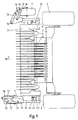
- a harvesting machine 1 In a harvesting machine 1, not shown in FIG. 1, is in the area in front of the front Impellers 2, which carry the entire machine, arranged an authorship drum 3. With their Aid is taken from the crops deposited in swaths on the field soil and used promoted further processing in the cutting machine 1.
- 3 side feed screws are on both side areas of the pickup drum 4 arranged that the picked crop to the width of the subsequent Merge conveyor 5.
- 3 support wheels 7 In support the pickup drum 3 on the field floor are 3 support wheels 7 in the area next to the side walls 6 of the pickup drum arranged. These are each via an assigned hydraulic cylinder 8 in a working and in a transport position swiveling.
- a hydraulic cylinder 8 is arranged, which is connected to the hydraulic system of the harvesting machine 1 communicates.
- the hydraulic cylinders 8 By operating the hydraulic cylinders 8 from the operator's platform of the harvesting machine 1 or the cab of a tractor from the coupling levers 13, 14 to the the coupling plate 11 attached bolt 12 moves and thereby the pivot plate 15 with the Wheel fork 17 and the support wheel 7 pivoted thereon pivoted in a horizontal plane.
- the support wheel 7 laterally next to the pickup drum 3 in the work or pivoted in front of the support arm 10 in the transport position. Is within the swivel range the support of the pickup drum 3 on the field floor by the support wheels 7 in each Intermediate position possible.
- the height of the support wheels 7 is in the embodiment shown in Figures 2 and 3 manually adjustable compared to the pickup drum 3. This is at the Top of the support arm 10 is an adjusting plate 21 with a plurality of vertically offset bores 22 arranged. At the opposite position is on the side wall 6 of the Pickup drum 3 a similar profile plate 23, which is also provided with holes is. By means of a plug pin 24, the adjusting plate 21 with the profile plate 23 in the required Position locked together.
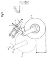
- FIG. 1 A further modification of the invention is shown in FIG.
- the implement side Pivot bearings 51 are set at an angle W with respect to the vertical. Is at this version of the hydraulic cylinder 8 is actuated, the coupling levers 13, 14 after shifted front and top. When the hydraulic cylinder 8 reaches its end stop, results an end position for the support wheel 7 which corresponds to the position 7 ′ shown in dash-dot lines corresponds.
- the pivot pin 16 and the wheel fork 17 are also in the end positions 16 ', 17 'relocated.
- the employment between the two possible end positions results in the Swivel bearing 51 and / or 52 by the angle W a height shift of the support wheel 7 the height value H.
Abstract
Description
Die Erfindung bezieht sich auf eine Schwenkeinrichtung für zwischen Anschlägen in einem Schwenkwinkel drehbar gelagerten Stützräder an Anbaugeräten für landwirtschaftliche Maschinen, insbesondere für Schwadautnahmeeinrichtungen an Feldhäckslern und Ballenpressen, aber auch andere gezogene oder angebaute Geräte wie Schneidwerke, Wender, Schwader, Mäbwerke etc., wobei die über Tragarme mit den Seitenwänden des Vorsatzgerätes verbundenen Stützräder zur Abstützung des Anbaugerätes am Feldboden dienen und die Stützräder in eine die Breite des Anbaugerätes vergrößernde und in eine die Breite des Anbaugeätes verringernde Stellung schwenkbar sind.The invention relates to a swivel device for between stops in one Swivel angle rotatably mounted support wheels on attachments for agricultural Machines, especially for swath picking devices on forage harvesters and balers, but also other trailed or attached devices such as cutting units, tedders, Rakes, mills, etc., with the support arms attached to the side walls of the front attachment connected support wheels to support the implement on the field floor and the Support wheels in a the width of the attachment and the width of the attachment reducing position are pivotable.
Anbaugeräte weisen Stützräder auf, um einerseits das Gewicht der Anbaugeräte zumindest teilweise auf dem Boden abzustützen und andererseits beweglich angeordnete Komponenten eines Anbaugerätes so zu steuern, daß dieses in seiner Verschwenkstellung die Bodenkontur kopiert. Dabei weisen die Stützräder eine um eine im wesentlichen vertikale Achse drehbare Lagerung auf, damit sich die Stützräder beim Durchfahren von Kurven dem Kurvenradius anpassen können und nicht über den Boden radieren. Um das Fahrverhalten ruhig zu halten und die Funktion abzusichern, ist der Schwenkwinkel auf einen sinnvollen Bereich, z.B. 45° durch Anschläge beschränkt, sodaß ein Stützrad aus der Geradeausstellung um jeweils 22,5 ° nach rechts und links verschwenkt werden kann. Zur Aufhahmemöglichkeit eines breiten Erntegutschwades bzw. zur Realisierung einer möglichst großen Arbeitsbreite eines Anbaugerätes weisen die Aufnahmeeinrichtungen insgesamt eine entsprechend große Breite auf Mit den zusätzlich an beiden seitlichen Bereichen angeordneten Stützrädern erreichen die Aufnahmeeinrichtungen und Anbaugeräte eine Breite, die größer als die Breite der übrigen Erntemaschine sein kann. Da dies zu Behinderungen bei Transportfahrten im öffentlichen Straßenverkehr beziehungsweise zu einer Überschreitung der zulässigen Fahrzeugbreite führt, sind bereits verschiedene Ausführungen bekannt, die die Breitenabmessungen in der Transportstellung reduzieren. Aber auch sonst kann sich die zusätzliche Breite durch die seitlich angeordneten Stützräder nachteilig auswirken, beispielsweise beim Manövrieren mit der landwirtschaftlichen Maschine.Attachments have support wheels, on the one hand, to at least support the weight of the attachments to be supported partly on the floor and on the other hand to have movably arranged components to control an attachment so that the bottom contour in its pivoting position copied. The support wheels have a substantially vertical axis rotatable Bearing on so that the support wheels when cornering the curve radius can adapt and not erase over the floor. To keep the driving behavior calm and to ensure the function, the swivel angle is to a reasonable range, e.g. 45 ° limited by stops, so that a support wheel from the straight-ahead position by 22.5 ° can be pivoted to the right and left. To accommodate a wide range Crop swaths or to implement the largest possible working width of an attachment overall, the receiving devices have a correspondingly large width the support wheels additionally arranged on both lateral areas reach the Pickups and attachments have a width that is larger than the width of the rest Harvester can be. As this leads to disabilities in public transportation Road traffic or the permissible vehicle width is exceeded, Various designs are already known, the width dimensions in the transport position to reduce. But also the additional width can be different from the side arranged support wheels adversely affect, for example when maneuvering with the agricultural machine.
So ist beispielsweise ein Vorsatzgerät für Erntemaschinen bekannt (DE 297 13 081 U1), dessen Stützräder in der Transportstellung durch eine von Hand ausgelöste Schwenkbewegung mittels zweier oder eines Doppelschwenklagers um zunächst 180° in eine Position hinter das Vorsatzgerät geschwenkt und anschließend noch zur Aufhebung des Kontaktes mit dem Feldboden angehoben werden. Obwohl mit dieser Ausführung die Stützräder in der Transportstellung gegenüber der Seitenwand des Vorsatzgerätes keinen Überstand mehr aufweisen, ist sowohl der konstruktiv dafür erforderliche Bauraumbedarf zwischen der Rückwand des Vorsatzgerärtes und den vorderen Laufrädern der Erntemaschine als auch der notwendige Aufwand für die manuelle Bedienung sehr hoch.For example, a front attachment for harvesting machines is known (DE 297 13 081 U1), its support wheels in the transport position by a swivel movement triggered by hand by means of two or a double swivel bearing initially in a position behind 180 ° the attachment is pivoted and then to remove contact with the Field floor to be raised. Although with this version the support wheels in the transport position no longer have a projection over the side wall of the front attachment both the design space required between the rear wall of the Attachments and the front wheels of the harvester as well as the necessary Manual operation very high.
Der Erfindung liegt die Aufgabe zugrunde, eine Schwenkeinrichtung für Stützräder so auszuführen, daß sowohl eine einfache Bedienbarkeit als auch eine bauraumgünstige Anordnung an der Erntemaschine erreicht wird, wobei die Laufrichtung der Stützräder trotz der Verschwenkung annähernd beibehalten wird.The invention has for its object to perform a swivel device for support wheels so that both ease of use and a space-saving arrangement the harvesting machine is reached, the direction of rotation of the support wheels despite the pivoting is approximately maintained.
Erfindungsgemäß wird diese Aufgabe durch die im Schutzanspruch 1 genannten Merkmale gelöst. Weitere vorteilhafte Ausführungen des Erfindungsgegenstandes ergeben sich aus den nachgeordneten Ansprüchen.According to the invention, this object is achieved by the features mentioned in claim 1 solved. Further advantageous embodiments of the subject matter of the invention result from the subordinate claims.
Die erfindungsgemäße Ausführung ermöglicht erlaubt es, durch mindestens zwei Koppelhebel den Schwenkbolzen in einer Position zu halten, in der die Stützräder trotz der Anschläge in beiden Endlagen weiterhin geradeaus laufen können. Wenn die Koppelhebel parallel zueinander verschwenkt werden, bleiben die Freiheitsgrade zwischen den beiden Anschlägen, zwischen denen sich das Stützrad drehen kann, unabhängig von der Verschwenkstellung erhalten. Bei einer Befestigung der Koppelhebel an einem schwenkbar gelagerten Tragarm kann neben der seitlichen Verschwenkung auch eine Höheneinstellung vorgenommen werden. Wenn die Koppelhebel um nicht senkrecht angeordnete Schwenklager verschwenkbar sind, kombiniert die Verschwenkbewegung eine seitliche Verlagerung der Stützräder mit einer Veränderung der Höhenlage. Durch die hydraulische Betätigung der Schwenkeinrichtung vom Fahrerstand der Emtemaschine aus wird eine einfache Bedienung möglich. Bei einer Kombination der nicht senkrecht angeordneten Schwenklager mit einer hydraulischen Betätigung können durch Ausfahren der Hydraulikzlinder die Stützräder von einer niedrigen seitlichen in eine höhere vor dem Anbaugerät befindliche Schwenkposition verlagert werden. In jeder Position zwischen der maximalen niedrigen seitlichen wie auch maximalen höheren vorderen Position der Stützräder können diese das Anbaugerät abstützen, sodaß durch die erfindungsgemäße Anordnung eine fernbetätigbare stufenlose Höhenanpassung des Anbaugerätes möglich ist. Auch in der Transportstellung schützen die vorgeschwenkten Stützräder das Anbaugerät vor möglichen Kollisionen mit Hindernissen oder vor Straßenunebenheiten. Alle genannten Vorteile sind mit leichen Einschränkungen auch bei manueller Betätigung erzielbar. Bei einer unterschiedlich steuerbaren Ausfahrposition der Hydraulikzylinder in Kombination mit nicht senkrecht angeordneten Schwenklagern läßt sich eine aktive, möglicherweise von einer zusätzlichen Steuerelektronik geregelte Verschwenkung des von den Stützrädern abgestützen Anbaugerätes erzielen. Infolge der vorteilhaften Ausbildung des Schwenkmechanismusses und der günstigen Anordnung der Stützräder ergibt sich insgesamt ein geringer BauraumbedarfThe design according to the invention allows it to be by at least two coupling levers to keep the swivel pin in a position in which the support wheels despite the stops in both end positions can continue to run straight. If the coupling levers are parallel to each other are pivoted, the degrees of freedom remain between the two stops, between which the jockey wheel can rotate, regardless of the pivot position. When the coupling lever is fastened to a pivotably mounted support arm in addition to the lateral pivoting, a height adjustment can also be carried out. If the coupling levers can be pivoted about pivot bearings which are not arranged vertically, combined the pivoting movement a lateral displacement of the support wheels with a change the altitude. By hydraulic actuation of the swivel device from Easy operation is possible from the driver's seat of the cutting machine. With a combination the non-vertically arranged swivel bearing with hydraulic actuation can extend the support wheels from a low lateral in by extending the hydraulic cylinder move to a higher swivel position in front of the attachment. In every Position between the maximum low side as well as maximum higher front Position of the support wheels, these can support the attachment, so that by the invention Arrangement of a remote-controlled, infinitely variable height adjustment of the attachment is possible. The swiveled support wheels also protect this in the transport position Attachment before possible collisions with obstacles or bumps on the road. All mentioned advantages can be achieved with slight restrictions even with manual operation. In a differently controllable extension position of the hydraulic cylinders in combination with non-vertically arranged swivel bearings, an active, possibly of an additional control electronics controlled pivoting of the support wheels achieve supported implement. As a result of the advantageous design of the swivel mechanism and the favorable arrangement of the support wheels results overall less Space requirements
Die Erfindung wird nachstehend an einem Ausführungsbeispiel näher erläutert. In der zugehörigen Zeichnung zeigen:
- Figur 1
- die Draufsicht auf eine Aufnehmertrommel mit Stützrädern, wobei sich das in Fahrtrichtung der Emtemaschine rechts angeordnete Stützrad in der Arbeitsstellung und das auf der linken Seite angeordnete Stützrad sich in der Transportstellung befindet,
Figur 2- eine Seitenansicht eines Stützrades in der Arbeitsstellung,
Figur 3- die Draufsicht auf ein Stützrad, wobei die Arbeitsstellung mit Vollinien und die Transportstellung mit Strich-Punkt-Linien dargestellt ist,
- Figur 4
- eine abgewandelte Seitenansicht, bei der ein Stützrad bei Verschwenkung höhenverlagert wird.
- Figure 1
- the top view of a take-up drum with support wheels, the support wheel arranged on the right in the direction of travel of the harvesting machine being in the working position and the support wheel arranged on the left side being in the transport position,
- Figure 2
- a side view of a support wheel in the working position,
- Figure 3
- the top view of a support wheel, the working position is shown with solid lines and the transport position with dash-dot lines,
- Figure 4
- a modified side view, in which a support wheel is shifted in height when pivoting.
Das Ausführungsbeispiel soll anhand einer Pickup- oder Authehmertrommel als Anbaugerät erläutert werden, was aber keineswegs bedeutet, daß die Anwendung der erfinderischen Idee auf dieses Ausführungsbeispiel begrenzt sein soll. Es läßt sich auf alle landwirtschaftlichen Geräte übertragen, die angebaut oder gezogen sind und die vollständig oder von denen nur einzelne Komponenten über Stützräder auf dem Boden abgestützt werden. Beispielsweise kommen auch Wender und Schwader oder Schneidwerke von Erntemaschinen in Betracht. Auch können beschriebene konstruktive Elemente durch bekannte Mittel ausgetauscht oder ergänzt werden, so beispielsweise der im Ausführungsbeispiel gezeigte einzelne Luftreifen durch ein Tademfahrwerk mit Doppelschwinge. Je nach Anforderungen können auch die Koppelhebel eine andere Form oder räumliche Lage aufweisen als im Ausführungsbeispiel gezeigt.The exemplary embodiment is intended to be used as an attachment using a pickup or authehm drum are explained, which in no way means that the application of the inventive idea should be limited to this embodiment. It can be applied to all agricultural Transfer equipment that is attached or pulled and that is complete or only of which individual components are supported on the floor via support wheels. For example tedders and rakes or harvester headers can also be considered. Described constructive elements can also be exchanged by known means or are supplemented, for example the single pneumatic tire shown in the exemplary embodiment through a gate chassis with double swing arm. Depending on the requirements, the Coupling levers have a different shape or spatial position than in the exemplary embodiment shown.
In einer in Figur 1 nicht näher dargestellten Erntemaschine 1 ist im Bereich vor den vorderen
Laufrädern 2, die die Gesamtmaschine tragen, eine Authehmertrommel 3 angeordnet. Mit ihrer
Hilfe wird das in Schwaden auf dem Feldboden abgelegte Emtegut aufgenommen und zur
weiteren Bearbeitung in die Emtemaschine 1 gefördert. Um eine große Aufnahmebreite zu
ermöglichen, sind an beiden Seitenbereichen der Aufnehmertrommel 3 seitliche Zuführschnekken
4 angeordnet, die das aufgenommene Erntegut auf die Breite der anschließenden
Fördereinrichtung 5 zusammenführen. Zur Abstützung der Aufnehmertrommel 3 am Feldboden
sind im Bereich neben den Seitenwänden 6 der Aufnehmertrommel 3 Stützräder 7
angeordnet. Diese sind über je einen zugeordneten Hydraulikzylinder 8 in eine Arbeits- und in
eine Transportstellung schwenkbar. An den Seitenwänden 6 der Aufnehmertrommel 3 ist ein
etwa horizontal verlaufender Lagerzapfen 9 befestigt, an dem ein höhenverschwenkbarer
Tragarm 10 angeordnet ist. Am vorderen freien Ende des parallel zur Seitenwand 6 der
Aufnehmertrommel 3 verlaufenden Tragarmes 10 sind Koppelplatten 11 befestigt, an denen an
festehenden Bolzen 12 Koppelhebel 13, 14 schwenkbeweglich angeschlossen sind, die mit
Schwenkplatten 15 verbunden sind. Zusätzlich zu den zwei Koppelhebeln können noch
weitere Koppelhebel vorgesehen werden, je nachdem, welche Belastungen aufgenommen und
welche Schwenkbewegungen vorgenommen werden sollen. Die Schwenkplatten 15 stehen
über einen vertikal angeordneten Schwenkbolzen 16 mit einer Radgabel 17 zur Aufnahme des
Stützrades 7 in Verbindung. Die in Figur 1 gezeigte Ausführung kann manuell betätigt
werden.In a harvesting machine 1, not shown in FIG. 1, is in the area in front of the
Zwischen einer seitlichen Konsole 18 am Tragarm 10 und einer mit dem Koppelhebel 14
verbundenen Halterung 19 ist in den Figuren 2 und 3 gemäß einer Ausgestaltung der Erfindung
ein Hydraulikzylinder 8 angeordnet, der mit dem Hydrauliksystem der Erntemaschine 1
in Verbindung steht. Durch das Betätigen der Hydraulikzylinder 8 vom Fahrerstand der Erntemaschine
1 oder der Kabine einer Zugmaschine aus werden die Koppelhebel 13, 14 um die an
der Koppelplatte 11 befestigten Bolzen 12 bewegt und dadurch die Schwenkplatte 15 mit der
Radgabel 17 und dem daran gelagerten Stützrad 7 in einer horizontalen Ebene geschwenkt.
Entsprechend der jeweiligen Bewegungsrichtung der Kolbenstange 20 des Hydraulikzylinders
8 wird das Stützrad 7 seitlich neben die Aufnehmertrommel 3 in die Arbeits- beziehungsweise
vor dem Tragarm 10 in die Transportstellung geschwenkt. Innerhalb des Schwenkbereiches ist
die Abstützung der Aufnehmertrommel 3 am Feldboden durch die Stützräder 7 in jeder
Zwischenstellung möglich.Between a
Die Höhenlage der Stützräder 7 ist in dem in Figuren 2 und 3 gezeigten Ausführungsbeispiel
gegenüber der Aufnehmertrommel 3 manuell einstellbar ausgebildet. Hierzu ist an der
Oberseite des Tragarms 10 ein Stellblech 21 mit mehreren höhenversetzten Bohrungen 22
angeordnet. An der gegenüberliegenden Position befindet sich an der Seitenwand 6 der
Aufnehmertrommel 3 ein gleichartiges Profilblech 23, das ebenfalls mit Bohrungen versehen
ist. Mittels eines Steckbolzens 24 wird das Stellblech 21 mit dem Profilblech 23 in der erforderlichen
Stellung miteinander arretiert.The height of the
In Figur 4 ist eine weitere Abwandlung der Erfindung gezeigt. Die anbaugeräteseitigen
Schwenklager 51 sind gegenüber der Senkrechten um einen Winkel W angestellt. Wird bei
dieser Ausführung der Hydraulikzylinder 8 betätigt, so werden die Koppelhebel 13, 14 nach
vorn und oben verlagert. Wenn der Hydraulikzylinder 8 seinen Endanschlag erreicht, ergibt
sich für das Stützrad 7 eine Endposition, die der strichpunktiert dargestellten Lage 7'
entspricht. Auch der Schwenkbolzen 16 und die Radgabel 17 sind in die Endpositionen 16',
17' verlagert. Zwischen den beiden möglichen Endlagen ergibt sich bei einer Anstellung der
Schwenklager 51 und/oder 52 um den Winkel W eine Höhenverlagerung des Stützrades 7 um
den Höhenwert H. A further modification of the invention is shown in FIG. The implement side
Pivot
- 11
- - Erntemaschine- harvester
- 22nd
- - Laufräder- wheels
- 33rd
- AufnehmertrommelPickup drum
- 44th
- - Zuführschnecken- feed screws
- 55
- - Fördereinrichtung- conveyor
- 66
- - Seitenwände- Side walls
- 77
- - Stützräder- training wheels
- 88th
- - Hydraulikzylinder- hydraulic cylinder
- 99
- - Lagerzapfen- journal
- 1010th
- - Tragarm- Beam
- 1111
- - Koppelplatten- coupling plates
- 1212th
- - Bolzen- Bolt
- 13, 1413, 14
- - Koppelhebel- coupling lever
- 1515
- - Schwenkplatten- swivel plates
- 1616
- - Schwenkbolzen- swivel pin
- 1717th
- - Radgabel- wheel fork
- 1818th
- - Konsole- console
- 1919th
- - Halterung- Bracket
- 2020th
- - Kolbenstange- piston rod
- 2121
- - Stellblech- shelf
- 2222
- - Bohrungen- holes
- 2323
- - Profilblech- Profile sheet
- 2424th
- - Steckbolzen- Plug pin
- 5151
- SchwenklagerSwivel bearing
- 5252
- SchwenldagerSchwenldager
- FF
- - Fahrtrichtung- Direction of travel
- HH
- - Höhe- Height
- WW
- - Winkel- Angle
- 7'7 '
- - Stützrad- jockey wheel
- 16'16 '
- - Schwenkbolzen- swivel pin
- 17'17 '
- - Radgabel- wheel fork
Claims (8)
dadurch gekennzeichnet, daß
der stützradseitige Schwenkbolzen (16) über mehrere schwenkbare Koppelhebel (13, 14) mit anbaugeräteseitigen Schwenklagern (51) verbunden ist.Swivel device for support wheels on attachments for agricultural machines rotatably mounted at a swivel angle between stops, the support wheels connected to the side walls of the attachment device via support arms serving to support the attachment or floor coping on the ground, and the support wheels in an enlarging the width of the attachment and in one the position reducing the width of the attachment can be pivoted,
characterized in that
the swivel pin (16) on the support wheel side is connected to swivel bearings (51) on the implement side by means of a plurality of swiveling coupling levers (13, 14).
dadurch gekennzeichnet, daß
die Schwenklager (51) auf einem schwenkbar gelagerten Tragarm (10) oder einer daran befestigten Koppelplatte (11) befestigt sind.Swivel device according to claim 1,
characterized in that
the pivot bearings (51) are fastened on a pivotably mounted support arm (10) or a coupling plate (11) fastened thereon.
dadurch gekennzeichnet, daß
die Schwenklager (51, 52), um die die Koppelhebel (13, 14) verschwenkbar sind, räumlich so angeordnet sind, daß die Koppelhebel (13, 14) in jeder Verschwenklage parallel zueinander liegen.Swivel device according to claim 1 or 2,
characterized in that
the pivot bearings (51, 52) about which the coupling levers (13, 14) can be pivoted are spatially arranged such that the coupling levers (13, 14) are parallel to each other in each pivoting position.
dadurch gekennzeichnet, daß
das Anbaugerät innerhalb des Schwenkbereiches der Stützräder zwischen der breiteren und schmaleren Stellung durch die Stützräder (7) in jeder Stellung abstützbar ist. Swivel device according to one or more of claims 1 to 3,
characterized in that
the attachment can be supported in any position within the swivel range of the support wheels between the wider and narrower positions by the support wheels (7).
dadurch gekennzeichnet, daß
die Stützräder (7) in der Transportstellung in Fahrtrichtung (F) gesehen vor die Tragarme (10) schwenkbar sind.Swivel device according to one or more of claims 1 to 4,
characterized in that
the support wheels (7) in the transport position in the direction of travel (F) can be pivoted in front of the support arms (10).
dadurch gekennzeichnet, daß
die Koppelhebel (13, 14) um nicht senkrecht angeordnete Schwenklager (51, 52) verschwenkbar sind.Swivel device according to one or more of claims 1 to 5,
characterized in that
the coupling levers (13, 14) can be pivoted about pivot bearings (51, 52) which are not arranged vertically.
dadurch gekennzeichnet, daß
zwischen einer seitlich an Tragarm (10) befestigten Konsole (18) und einer mit den Koppelhebeln (14) verbundenen Halterung (19) ein Hydraulikzylinder (8) angeordnet ist.Swivel device according to one or more of claims 1 to 6,
characterized in that
A hydraulic cylinder (8) is arranged between a bracket (18) attached to the side of the support arm (10) and a bracket (19) connected to the coupling levers (14).
dadurch gekennzeichnet, daß
mehrere Hydraulikzylinder (8) durch entsprechende Hydraulikventile in voneinander abweichende Ausfahrstellungen bringbar sind.Swivel device according to claim 7,
characterized in that
a plurality of hydraulic cylinders (8) can be brought into different extension positions by corresponding hydraulic valves.
Applications Claiming Priority (2)
| Application Number | Priority Date | Filing Date | Title |
|---|---|---|---|
| DE19919309 | 1999-04-28 | ||
| DE19919309A DE19919309A1 (en) | 1999-04-28 | 1999-04-28 | Swivel device for support wheels |
Publications (2)
| Publication Number | Publication Date |
|---|---|
| EP1048195A1 true EP1048195A1 (en) | 2000-11-02 |
| EP1048195B1 EP1048195B1 (en) | 2004-09-08 |
Family
ID=7906160
Family Applications (1)
| Application Number | Title | Priority Date | Filing Date |
|---|---|---|---|
| EP00108455A Expired - Lifetime EP1048195B1 (en) | 1999-04-28 | 2000-04-18 | Pivoting device for support wheels |
Country Status (4)
| Country | Link |
|---|---|
| US (1) | US6336313B1 (en) |
| EP (1) | EP1048195B1 (en) |
| AT (1) | ATE275322T1 (en) |
| DE (2) | DE19919309A1 (en) |
Cited By (3)
| Publication number | Priority date | Publication date | Assignee | Title |
|---|---|---|---|---|
| EP2113396A1 (en) * | 2008-04-29 | 2009-11-04 | Maschinenfabrik Kemper GmbH & Co. KG | Support wheel assembly for a swath pick-up with self-actuated retainer in transport position |
| WO2010130745A1 (en) * | 2009-05-15 | 2010-11-18 | Cnh Belgium N.V. | A harvester with an attachment for a support wheel and a method for storing a support wheel of a harvester |
| NL2008876A (en) * | 2011-05-27 | 2012-11-28 | Alois P Ttinger Maschinenfabrik Ges M B H | AGRICULTURAL TOOL. |
Families Citing this family (13)
| Publication number | Priority date | Publication date | Assignee | Title |
|---|---|---|---|---|
| DE102007053568A1 (en) | 2007-11-09 | 2009-05-14 | Alois Pöttinger Maschinenfabrik Gmbh | Harvester, particularly trailer with loading facility and bailing press, has receiving device for receiving product harvested from earth and cross conveyor, which has cross conveyor rollers assigned to lateral edge areas of receiving rotor |
| DE102011013243B4 (en) | 2011-03-07 | 2023-01-05 | Pöttinger Landtechnik Gmbh | harvester |
| DK2656716T3 (en) * | 2012-04-26 | 2019-09-16 | Macdon Ind Ltd | Transport system for harvester-type harvester, where the machine remains balanced on transport wheels and coupling device when the transport system is used |
| BE1021113B1 (en) | 2012-10-01 | 2015-12-18 | Cnh Industrial Belgium Nv | SWIVEL WHEEL WHOLE OF A GRAPHER FOR A AGRICULTURAL MACHINE |
| US9622404B2 (en) | 2013-09-11 | 2017-04-18 | Cnh Industrial America Llc | Integral lateral transport of a mower |
| US9596808B2 (en) | 2014-04-30 | 2017-03-21 | Cnh Industrial America Llc | Transport system for a center pivot agricultural machine |
| US9386748B2 (en) | 2014-05-02 | 2016-07-12 | Cnh Industrial America Llc | Transport system for a header of an agricultural harvester |
| US9603306B2 (en) | 2014-07-09 | 2017-03-28 | Cnh Industrial America Llc | Agricultural machine with retaining elements for retaining a header in an elevated position |
| US9565800B2 (en) | 2014-09-08 | 2017-02-14 | Cnh Industrial America Llc | Windrow shield control system for a header of an agricultural harvester |
| CN104443109A (en) * | 2014-09-09 | 2015-03-25 | 泰安海松机械有限公司 | Agricultural high land gap operation machine |
| US10779473B2 (en) * | 2018-04-18 | 2020-09-22 | Cnh Industrial America Llc | Harvester header support |
| DE102019006298B4 (en) | 2019-09-06 | 2022-03-24 | Maschinenfabrik Bernard Krone GmbH & Co. KG | Mounting device for an agricultural working machine, agricultural working machine and work train with such an agricultural working machine |
| DE102022105847A1 (en) | 2022-03-14 | 2023-09-14 | Deere & Company | Swath pickup with third support wheel |
Citations (6)
| Publication number | Priority date | Publication date | Assignee | Title |
|---|---|---|---|---|
| FR1072827A (en) * | 1953-03-10 | 1954-09-16 | Cima | Attachment device for transport wheels for coupled agricultural machinery |
| DE1072892B (en) * | 1960-01-07 | C. van der LeIy N. V., Ma*sland (Niederlande) | Schl'epperwheel axle | |
| US3899037A (en) * | 1973-07-16 | 1975-08-12 | Paul A Yuker | Chassis apparatus for all terrain vehicles |
| FR2309127A1 (en) * | 1975-05-02 | 1976-11-26 | Clayson Nv | AGRICULTURAL MACHINES CONTAINING ELASTICALLY MOUNTED EQUIPMENT |
| DE4304931A1 (en) * | 1993-02-18 | 1994-08-25 | Amazonen Werke Dreyer H | Direct-sowing seed drill |
| DE29713081U1 (en) | 1997-07-23 | 1997-09-25 | Claas Usines France | Header with support wheels |
Family Cites Families (14)
| Publication number | Priority date | Publication date | Assignee | Title |
|---|---|---|---|---|
| US3106971A (en) * | 1957-08-09 | 1963-10-15 | Case Co J I | Agricultural implement |
| US2981344A (en) * | 1959-03-10 | 1961-04-25 | Int Harvester Co | Plow furrow wheel |
| DD50143A1 (en) * | 1966-01-24 | 1966-10-15 | Jockey wheel or pair of jockey wheels, especially for agricultural machinery and equipment | |
| US3540512A (en) * | 1967-12-26 | 1970-11-17 | Goodrich Co B F | Pneumatic tire |
| US4034623A (en) * | 1974-02-13 | 1977-07-12 | Ideal Industries, Inc. | Folding mechanism for hinged implement frame extensions |
| US3986464A (en) * | 1975-03-10 | 1976-10-19 | Acme Manufacturing Company, Inc. | Row crop planting machine |
| US4360215A (en) * | 1981-05-07 | 1982-11-23 | Nohl Arthur H | Drill hitch transport |
| US4402367A (en) * | 1981-06-15 | 1983-09-06 | Couser Chester F | Folding tool beam and lift assembly |
| US4415043A (en) * | 1981-10-01 | 1983-11-15 | Chromalloy American Corporation | Toolbar with wings foldable substantially 180 degrees |
| US4664202A (en) * | 1984-09-07 | 1987-05-12 | Great Plains Manufacturing, Inc. | Folding implement frame for grain drills and the like |
| US4862758A (en) * | 1986-06-06 | 1989-09-05 | J. I. Case Company | Hinge assembly for folding implement frame |
| US5054560A (en) * | 1990-08-07 | 1991-10-08 | Deere & Company | Transporting caster wheels |
| DE9102354U1 (en) * | 1991-02-28 | 1991-05-16 | Fortschritt Erntemaschinen Gmbh, O-8355 Neustadt, De | |
| US5253717A (en) * | 1992-01-30 | 1993-10-19 | Case Corporation | Foldable agricultural implement |
-
1999
- 1999-04-28 DE DE19919309A patent/DE19919309A1/en not_active Withdrawn
-
2000
- 2000-04-18 EP EP00108455A patent/EP1048195B1/en not_active Expired - Lifetime
- 2000-04-18 DE DE50007655T patent/DE50007655D1/en not_active Expired - Lifetime
- 2000-04-18 AT AT00108455T patent/ATE275322T1/en not_active IP Right Cessation
- 2000-04-28 US US09/561,285 patent/US6336313B1/en not_active Expired - Fee Related
Patent Citations (6)
| Publication number | Priority date | Publication date | Assignee | Title |
|---|---|---|---|---|
| DE1072892B (en) * | 1960-01-07 | C. van der LeIy N. V., Ma*sland (Niederlande) | Schl'epperwheel axle | |
| FR1072827A (en) * | 1953-03-10 | 1954-09-16 | Cima | Attachment device for transport wheels for coupled agricultural machinery |
| US3899037A (en) * | 1973-07-16 | 1975-08-12 | Paul A Yuker | Chassis apparatus for all terrain vehicles |
| FR2309127A1 (en) * | 1975-05-02 | 1976-11-26 | Clayson Nv | AGRICULTURAL MACHINES CONTAINING ELASTICALLY MOUNTED EQUIPMENT |
| DE4304931A1 (en) * | 1993-02-18 | 1994-08-25 | Amazonen Werke Dreyer H | Direct-sowing seed drill |
| DE29713081U1 (en) | 1997-07-23 | 1997-09-25 | Claas Usines France | Header with support wheels |
Cited By (8)
| Publication number | Priority date | Publication date | Assignee | Title |
|---|---|---|---|---|
| EP2113396A1 (en) * | 2008-04-29 | 2009-11-04 | Maschinenfabrik Kemper GmbH & Co. KG | Support wheel assembly for a swath pick-up with self-actuated retainer in transport position |
| WO2010130745A1 (en) * | 2009-05-15 | 2010-11-18 | Cnh Belgium N.V. | A harvester with an attachment for a support wheel and a method for storing a support wheel of a harvester |
| BE1018757A3 (en) * | 2009-05-15 | 2011-08-02 | Cnh Belgium Nv | A HARVESTER WITH A FIXING DEVICE FOR A SUPPORT WHEEL AND A METHOD FOR STORING A SUPPORT WHEEL OF A HARVESTING MACHINE. |
| CN102395260A (en) * | 2009-05-15 | 2012-03-28 | Cnh比利时股份有限公司 | A harvester with an attachment for a support wheel and a method for storing a support wheel of a harvester |
| US20120132768A1 (en) * | 2009-05-15 | 2012-05-31 | Eddy Lammerant | Harvester with an Attachment for a Support Wheel and a Method for Storing a Support Wheel of a Harvester |
| US8910726B2 (en) * | 2009-05-15 | 2014-12-16 | Cnh Industrial America Llc | Harvester with an attachment for a support wheel and a method for storing a support wheel of a harvester |
| NL2008876A (en) * | 2011-05-27 | 2012-11-28 | Alois P Ttinger Maschinenfabrik Ges M B H | AGRICULTURAL TOOL. |
| FR2975565A1 (en) * | 2011-05-27 | 2012-11-30 | Poettinger Alois Maschf | Agricultural machine e.g. loading wagon connected to tractor, has wheel that is pivoted between working and transport positions by tilting the pivot arm together with pivot axis relative to working unit and mounting bracket |
Also Published As
| Publication number | Publication date |
|---|---|
| DE19919309A1 (en) | 2000-11-02 |
| US6336313B1 (en) | 2002-01-08 |
| DE50007655D1 (en) | 2004-10-14 |
| ATE275322T1 (en) | 2004-09-15 |
| EP1048195B1 (en) | 2004-09-08 |
Similar Documents
| Publication | Publication Date | Title |
|---|---|---|
| EP1048195B1 (en) | Pivoting device for support wheels | |
| EP2186713B1 (en) | Ballast device and agricultural vehicle with such device | |
| DE1950497B2 (en) | Tractor with a loading area for payloads | |
| DE10121014A1 (en) | mowing | |
| DE1932229B2 (en) | HAYMAKING MACHINE | |
| DE102019201337A1 (en) | Agricultural implement, drawbar device and tractor-implement combination | |
| EP0807377A2 (en) | Device for connecting a height adjustable implement to a vehicle from a working in a transport position | |
| EP0063774A1 (en) | Implement-attaching device for an agricultural tractor | |
| DE19534695C2 (en) | Rear mower that can be attached to a tractor | |
| EP2082637B9 (en) | Agricultural machine with a swivelling and fixable middle drawbar | |
| EP1163830A1 (en) | Drawn agricultural implement | |
| EP1894462A1 (en) | Agricultural carrier vehicle | |
| DE102013209740B4 (en) | Agricultural implement | |
| DE102012108904A1 (en) | Device mounting device of a work vehicle | |
| EP4101275A1 (en) | Field working attachment | |
| EP1023825B1 (en) | Suspension and working device or vehicle | |
| EP4074156A1 (en) | Drawbar assembly for a towed agricultural machine | |
| EP3788864B1 (en) | Mounting device for an agricultural working machine, agricultural working machine and work train with such an agricultural working machine | |
| EP4019301A1 (en) | Axle device with variable track width, special vehicle and use of the same | |
| DE2349176B2 (en) | Rake | |
| DE4112155C1 (en) | ||
| EP3689119B1 (en) | Agricultural working device, drawbar device and traction vehicle working device combination | |
| EP1782674B1 (en) | Mowing machine | |
| DE2750094C2 (en) | ||
| EP1779717A1 (en) | Improving the visibility in self-propelled working machines |
Legal Events
| Date | Code | Title | Description |
|---|---|---|---|
| PUAI | Public reference made under article 153(3) epc to a published international application that has entered the european phase |
Free format text: ORIGINAL CODE: 0009012 |
|
| AK | Designated contracting states |
Kind code of ref document: A1 Designated state(s): AT BE CH CY DE DK ES FI FR GB GR IE IT LI LU MC NL PT SE |
|
| AX | Request for extension of the european patent |
Free format text: AL;LT;LV;MK;RO;SI |
|
| 17P | Request for examination filed |
Effective date: 20010502 |
|
| AKX | Designation fees paid |
Free format text: AT BE CH CY DE DK ES FI FR GB GR IE IT LI LU MC NL PT SE |
|
| 17Q | First examination report despatched |
Effective date: 20030219 |
|
| GRAP | Despatch of communication of intention to grant a patent |
Free format text: ORIGINAL CODE: EPIDOSNIGR1 |
|
| GRAS | Grant fee paid |
Free format text: ORIGINAL CODE: EPIDOSNIGR3 |
|
| GRAA | (expected) grant |
Free format text: ORIGINAL CODE: 0009210 |
|
| AK | Designated contracting states |
Kind code of ref document: B1 Designated state(s): AT BE CH CY DE DK ES FI FR GB GR IE IT LI LU MC NL PT SE |
|
| PG25 | Lapsed in a contracting state [announced via postgrant information from national office to epo] |
Ref country code: IT Free format text: LAPSE BECAUSE OF FAILURE TO SUBMIT A TRANSLATION OF THE DESCRIPTION OR TO PAY THE FEE WITHIN THE PRE;WARNING: LAPSES OF ITALIAN PATENTS WITH EFFECTIVE DATE BEFORE 2007 MAY HAVE OCCURRED AT ANY TIME BEFORE 2007. THE CORRECT EFFECTIVE DATE MAY BE DIFFERENT FROM THE ONE RECORDED.SCRIBED TIME-LIMIT Effective date: 20040908 Ref country code: FI Free format text: LAPSE BECAUSE OF FAILURE TO SUBMIT A TRANSLATION OF THE DESCRIPTION OR TO PAY THE FEE WITHIN THE PRESCRIBED TIME-LIMIT Effective date: 20040908 Ref country code: IE Free format text: LAPSE BECAUSE OF FAILURE TO SUBMIT A TRANSLATION OF THE DESCRIPTION OR TO PAY THE FEE WITHIN THE PRESCRIBED TIME-LIMIT Effective date: 20040908 Ref country code: NL Free format text: LAPSE BECAUSE OF FAILURE TO SUBMIT A TRANSLATION OF THE DESCRIPTION OR TO PAY THE FEE WITHIN THE PRESCRIBED TIME-LIMIT Effective date: 20040908 |
|
| REG | Reference to a national code |
Ref country code: GB Ref legal event code: FG4D Free format text: NOT ENGLISH |
|
| REG | Reference to a national code |
Ref country code: CH Ref legal event code: EP |
|
| REG | Reference to a national code |
Ref country code: IE Ref legal event code: FG4D Free format text: GERMAN |
|
| REF | Corresponds to: |
Ref document number: 50007655 Country of ref document: DE Date of ref document: 20041014 Kind code of ref document: P |
|
| PG25 | Lapsed in a contracting state [announced via postgrant information from national office to epo] |
Ref country code: DK Free format text: LAPSE BECAUSE OF FAILURE TO SUBMIT A TRANSLATION OF THE DESCRIPTION OR TO PAY THE FEE WITHIN THE PRESCRIBED TIME-LIMIT Effective date: 20041208 Ref country code: GR Free format text: LAPSE BECAUSE OF FAILURE TO SUBMIT A TRANSLATION OF THE DESCRIPTION OR TO PAY THE FEE WITHIN THE PRESCRIBED TIME-LIMIT Effective date: 20041208 Ref country code: SE Free format text: LAPSE BECAUSE OF FAILURE TO SUBMIT A TRANSLATION OF THE DESCRIPTION OR TO PAY THE FEE WITHIN THE PRESCRIBED TIME-LIMIT Effective date: 20041208 |
|
| PG25 | Lapsed in a contracting state [announced via postgrant information from national office to epo] |
Ref country code: ES Free format text: LAPSE BECAUSE OF FAILURE TO SUBMIT A TRANSLATION OF THE DESCRIPTION OR TO PAY THE FEE WITHIN THE PRESCRIBED TIME-LIMIT Effective date: 20041219 |
|
| GBT | Gb: translation of ep patent filed (gb section 77(6)(a)/1977) |
Effective date: 20041206 |
|
| NLV1 | Nl: lapsed or annulled due to failure to fulfill the requirements of art. 29p and 29m of the patents act | ||
| ET | Fr: translation filed | ||
| PG25 | Lapsed in a contracting state [announced via postgrant information from national office to epo] |
Ref country code: CY Free format text: LAPSE BECAUSE OF FAILURE TO SUBMIT A TRANSLATION OF THE DESCRIPTION OR TO PAY THE FEE WITHIN THE PRESCRIBED TIME-LIMIT Effective date: 20050418 Ref country code: LU Free format text: LAPSE BECAUSE OF NON-PAYMENT OF DUE FEES Effective date: 20050418 Ref country code: AT Free format text: LAPSE BECAUSE OF NON-PAYMENT OF DUE FEES Effective date: 20050418 |
|
| REG | Reference to a national code |
Ref country code: IE Ref legal event code: FD4D |
|
| PG25 | Lapsed in a contracting state [announced via postgrant information from national office to epo] |
Ref country code: CH Free format text: LAPSE BECAUSE OF NON-PAYMENT OF DUE FEES Effective date: 20050430 Ref country code: MC Free format text: LAPSE BECAUSE OF NON-PAYMENT OF DUE FEES Effective date: 20050430 Ref country code: LI Free format text: LAPSE BECAUSE OF NON-PAYMENT OF DUE FEES Effective date: 20050430 |
|
| PLBE | No opposition filed within time limit |
Free format text: ORIGINAL CODE: 0009261 |
|
| STAA | Information on the status of an ep patent application or granted ep patent |
Free format text: STATUS: NO OPPOSITION FILED WITHIN TIME LIMIT |
|
| 26N | No opposition filed |
Effective date: 20050609 |
|
| REG | Reference to a national code |
Ref country code: CH Ref legal event code: PL |
|
| PG25 | Lapsed in a contracting state [announced via postgrant information from national office to epo] |
Ref country code: PT Free format text: LAPSE BECAUSE OF NON-PAYMENT OF DUE FEES Effective date: 20050208 |
|
| PGFP | Annual fee paid to national office [announced via postgrant information from national office to epo] |
Ref country code: GB Payment date: 20150420 Year of fee payment: 16 |
|
| REG | Reference to a national code |
Ref country code: DE Ref legal event code: R084 Ref document number: 50007655 Country of ref document: DE |
|
| REG | Reference to a national code |
Ref country code: FR Ref legal event code: PLFP Year of fee payment: 17 |
|
| GBPC | Gb: european patent ceased through non-payment of renewal fee |
Effective date: 20160418 |
|
| PG25 | Lapsed in a contracting state [announced via postgrant information from national office to epo] |
Ref country code: GB Free format text: LAPSE BECAUSE OF NON-PAYMENT OF DUE FEES Effective date: 20160418 |
|
| REG | Reference to a national code |
Ref country code: FR Ref legal event code: PLFP Year of fee payment: 18 |
|
| REG | Reference to a national code |
Ref country code: FR Ref legal event code: PLFP Year of fee payment: 19 |
|
| PGFP | Annual fee paid to national office [announced via postgrant information from national office to epo] |
Ref country code: DE Payment date: 20180307 Year of fee payment: 19 |
|
| PGFP | Annual fee paid to national office [announced via postgrant information from national office to epo] |
Ref country code: FR Payment date: 20180420 Year of fee payment: 19 Ref country code: BE Payment date: 20180418 Year of fee payment: 19 |
|
| REG | Reference to a national code |
Ref country code: DE Ref legal event code: R119 Ref document number: 50007655 Country of ref document: DE |
|
| REG | Reference to a national code |
Ref country code: BE Ref legal event code: MM Effective date: 20190430 |
|
| PG25 | Lapsed in a contracting state [announced via postgrant information from national office to epo] |
Ref country code: DE Free format text: LAPSE BECAUSE OF NON-PAYMENT OF DUE FEES Effective date: 20191101 |
|
| PG25 | Lapsed in a contracting state [announced via postgrant information from national office to epo] |
Ref country code: BE Free format text: LAPSE BECAUSE OF NON-PAYMENT OF DUE FEES Effective date: 20190430 Ref country code: FR Free format text: LAPSE BECAUSE OF NON-PAYMENT OF DUE FEES Effective date: 20190430 |