EP1467663B1 - Dispositif vaso-occlusif a microbobine et a configuration multi-axe secondaire - Google Patents
Dispositif vaso-occlusif a microbobine et a configuration multi-axe secondaire Download PDFInfo
- Publication number
- EP1467663B1 EP1467663B1 EP03707353A EP03707353A EP1467663B1 EP 1467663 B1 EP1467663 B1 EP 1467663B1 EP 03707353 A EP03707353 A EP 03707353A EP 03707353 A EP03707353 A EP 03707353A EP 1467663 B1 EP1467663 B1 EP 1467663B1
- Authority
- EP
- European Patent Office
- Prior art keywords
- loops
- aneurysm
- configuration
- energy state
- microcoil
- Prior art date
- Legal status (The legal status is an assumption and is not a legal conclusion. Google has not performed a legal analysis and makes no representation as to the accuracy of the status listed.)
- Expired - Lifetime
Links
- 238000004804 winding Methods 0.000 claims description 16
- 230000003247 decreasing effect Effects 0.000 claims description 3
- 206010002329 Aneurysm Diseases 0.000 abstract description 61
- 230000002792 vascular Effects 0.000 abstract description 18
- 230000017531 blood circulation Effects 0.000 abstract description 6
- 238000005056 compaction Methods 0.000 abstract description 5
- 239000000463 material Substances 0.000 description 13
- BASFCYQUMIYNBI-UHFFFAOYSA-N platinum Chemical compound [Pt] BASFCYQUMIYNBI-UHFFFAOYSA-N 0.000 description 13
- 230000010102 embolization Effects 0.000 description 11
- 210000003739 neck Anatomy 0.000 description 9
- 229920000642 polymer Polymers 0.000 description 9
- IAZDPXIOMUYVGZ-UHFFFAOYSA-N Dimethylsulphoxide Chemical compound CS(C)=O IAZDPXIOMUYVGZ-UHFFFAOYSA-N 0.000 description 8
- 210000001367 artery Anatomy 0.000 description 6
- 239000007788 liquid Substances 0.000 description 6
- 238000000034 method Methods 0.000 description 6
- 229910052697 platinum Inorganic materials 0.000 description 6
- 239000003795 chemical substances by application Substances 0.000 description 5
- 210000004204 blood vessel Anatomy 0.000 description 4
- 230000003073 embolic effect Effects 0.000 description 4
- 238000010438 heat treatment Methods 0.000 description 4
- 238000002347 injection Methods 0.000 description 4
- 239000007924 injection Substances 0.000 description 4
- 229910052751 metal Inorganic materials 0.000 description 4
- 239000002184 metal Substances 0.000 description 4
- 239000013598 vector Substances 0.000 description 4
- 201000008450 Intracranial aneurysm Diseases 0.000 description 3
- 238000004519 manufacturing process Methods 0.000 description 3
- 238000011282 treatment Methods 0.000 description 3
- 229910052721 tungsten Inorganic materials 0.000 description 3
- 229910000990 Ni alloy Inorganic materials 0.000 description 2
- KDLHZDBZIXYQEI-UHFFFAOYSA-N Palladium Chemical compound [Pd] KDLHZDBZIXYQEI-UHFFFAOYSA-N 0.000 description 2
- 229910001069 Ti alloy Inorganic materials 0.000 description 2
- RTAQQCXQSZGOHL-UHFFFAOYSA-N Titanium Chemical compound [Ti] RTAQQCXQSZGOHL-UHFFFAOYSA-N 0.000 description 2
- 238000000137 annealing Methods 0.000 description 2
- 238000013459 approach Methods 0.000 description 2
- LYCAIKOWRPUZTN-UHFFFAOYSA-N ethylene glycol Natural products OCCO LYCAIKOWRPUZTN-UHFFFAOYSA-N 0.000 description 2
- 239000012530 fluid Substances 0.000 description 2
- 230000007246 mechanism Effects 0.000 description 2
- 238000012986 modification Methods 0.000 description 2
- 230000004048 modification Effects 0.000 description 2
- 229910001000 nickel titanium Inorganic materials 0.000 description 2
- HLXZNVUGXRDIFK-UHFFFAOYSA-N nickel titanium Chemical compound [Ti].[Ti].[Ti].[Ti].[Ti].[Ti].[Ti].[Ti].[Ti].[Ti].[Ti].[Ni].[Ni].[Ni].[Ni].[Ni].[Ni].[Ni].[Ni].[Ni].[Ni].[Ni].[Ni].[Ni].[Ni] HLXZNVUGXRDIFK-UHFFFAOYSA-N 0.000 description 2
- 230000002028 premature Effects 0.000 description 2
- 230000008569 process Effects 0.000 description 2
- 239000000047 product Substances 0.000 description 2
- 230000000541 pulsatile effect Effects 0.000 description 2
- 239000011819 refractory material Substances 0.000 description 2
- 229920005989 resin Polymers 0.000 description 2
- 239000011347 resin Substances 0.000 description 2
- 239000010936 titanium Substances 0.000 description 2
- WFKWXMTUELFFGS-UHFFFAOYSA-N tungsten Chemical compound [W] WFKWXMTUELFFGS-UHFFFAOYSA-N 0.000 description 2
- 239000010937 tungsten Substances 0.000 description 2
- 229920001651 Cyanoacrylate Polymers 0.000 description 1
- 229920004934 Dacron® Polymers 0.000 description 1
- MWCLLHOVUTZFKS-UHFFFAOYSA-N Methyl cyanoacrylate Chemical compound COC(=O)C(=C)C#N MWCLLHOVUTZFKS-UHFFFAOYSA-N 0.000 description 1
- 206010028980 Neoplasm Diseases 0.000 description 1
- 229910001260 Pt alloy Inorganic materials 0.000 description 1
- BQCADISMDOOEFD-UHFFFAOYSA-N Silver Chemical compound [Ag] BQCADISMDOOEFD-UHFFFAOYSA-N 0.000 description 1
- 206010053648 Vascular occlusion Diseases 0.000 description 1
- 229910001080 W alloy Inorganic materials 0.000 description 1
- 229910045601 alloy Inorganic materials 0.000 description 1
- 239000000956 alloy Substances 0.000 description 1
- 230000004323 axial length Effects 0.000 description 1
- WMWLMWRWZQELOS-UHFFFAOYSA-N bismuth(III) oxide Inorganic materials O=[Bi]O[Bi]=O WMWLMWRWZQELOS-UHFFFAOYSA-N 0.000 description 1
- 230000000740 bleeding effect Effects 0.000 description 1
- 239000008280 blood Substances 0.000 description 1
- 210000004369 blood Anatomy 0.000 description 1
- 230000036770 blood supply Effects 0.000 description 1
- 229920002301 cellulose acetate Polymers 0.000 description 1
- 210000004720 cerebrum Anatomy 0.000 description 1
- 238000010276 construction Methods 0.000 description 1
- 239000002872 contrast media Substances 0.000 description 1
- 229920001577 copolymer Polymers 0.000 description 1
- 238000011161 development Methods 0.000 description 1
- 230000018109 developmental process Effects 0.000 description 1
- 238000009826 distribution Methods 0.000 description 1
- 239000000835 fiber Substances 0.000 description 1
- PCHJSUWPFVWCPO-UHFFFAOYSA-N gold Chemical compound [Au] PCHJSUWPFVWCPO-UHFFFAOYSA-N 0.000 description 1
- 229910052737 gold Inorganic materials 0.000 description 1
- 239000010931 gold Substances 0.000 description 1
- 238000011065 in-situ storage Methods 0.000 description 1
- QRWOVIRDHQJFDB-UHFFFAOYSA-N isobutyl cyanoacrylate Chemical compound CC(C)COC(=O)C(=C)C#N QRWOVIRDHQJFDB-UHFFFAOYSA-N 0.000 description 1
- 239000002905 metal composite material Substances 0.000 description 1
- 229910001092 metal group alloy Inorganic materials 0.000 description 1
- 150000002739 metals Chemical class 0.000 description 1
- 238000013508 migration Methods 0.000 description 1
- 230000005012 migration Effects 0.000 description 1
- 229910052763 palladium Inorganic materials 0.000 description 1
- 239000005020 polyethylene terephthalate Substances 0.000 description 1
- 230000000379 polymerizing effect Effects 0.000 description 1
- 239000002244 precipitate Substances 0.000 description 1
- 230000002441 reversible effect Effects 0.000 description 1
- 229910052702 rhenium Inorganic materials 0.000 description 1
- WUAPFZMCVAUBPE-UHFFFAOYSA-N rhenium atom Chemical compound [Re] WUAPFZMCVAUBPE-UHFFFAOYSA-N 0.000 description 1
- 229910052703 rhodium Inorganic materials 0.000 description 1
- 239000010948 rhodium Substances 0.000 description 1
- MHOVAHRLVXNVSD-UHFFFAOYSA-N rhodium atom Chemical compound [Rh] MHOVAHRLVXNVSD-UHFFFAOYSA-N 0.000 description 1
- 229910052709 silver Inorganic materials 0.000 description 1
- 239000004332 silver Substances 0.000 description 1
- 238000007711 solidification Methods 0.000 description 1
- 230000008023 solidification Effects 0.000 description 1
- 239000000243 solution Substances 0.000 description 1
- 229910001220 stainless steel Inorganic materials 0.000 description 1
- 229910052715 tantalum Inorganic materials 0.000 description 1
- GUVRBAGPIYLISA-UHFFFAOYSA-N tantalum atom Chemical compound [Ta] GUVRBAGPIYLISA-UHFFFAOYSA-N 0.000 description 1
- 230000002885 thrombogenetic effect Effects 0.000 description 1
- 238000011277 treatment modality Methods 0.000 description 1
- 208000021331 vascular occlusion disease Diseases 0.000 description 1
- 238000012800 visualization Methods 0.000 description 1
Images


Classifications
-
- A—HUMAN NECESSITIES
- A61—MEDICAL OR VETERINARY SCIENCE; HYGIENE
- A61B—DIAGNOSIS; SURGERY; IDENTIFICATION
- A61B17/00—Surgical instruments, devices or methods, e.g. tourniquets
- A61B17/12—Surgical instruments, devices or methods, e.g. tourniquets for ligaturing or otherwise compressing tubular parts of the body, e.g. blood vessels, umbilical cord
- A61B17/12022—Occluding by internal devices, e.g. balloons or releasable wires
- A61B17/12099—Occluding by internal devices, e.g. balloons or releasable wires characterised by the location of the occluder
- A61B17/12109—Occluding by internal devices, e.g. balloons or releasable wires characterised by the location of the occluder in a blood vessel
- A61B17/12113—Occluding by internal devices, e.g. balloons or releasable wires characterised by the location of the occluder in a blood vessel within an aneurysm
-
- A—HUMAN NECESSITIES
- A61—MEDICAL OR VETERINARY SCIENCE; HYGIENE
- A61B—DIAGNOSIS; SURGERY; IDENTIFICATION
- A61B17/00—Surgical instruments, devices or methods, e.g. tourniquets
- A61B17/12—Surgical instruments, devices or methods, e.g. tourniquets for ligaturing or otherwise compressing tubular parts of the body, e.g. blood vessels, umbilical cord
- A61B17/12022—Occluding by internal devices, e.g. balloons or releasable wires
- A61B17/12131—Occluding by internal devices, e.g. balloons or releasable wires characterised by the type of occluding device
- A61B17/1214—Coils or wires
- A61B17/12145—Coils or wires having a pre-set deployed three-dimensional shape
-
- A—HUMAN NECESSITIES
- A61—MEDICAL OR VETERINARY SCIENCE; HYGIENE
- A61B—DIAGNOSIS; SURGERY; IDENTIFICATION
- A61B17/00—Surgical instruments, devices or methods, e.g. tourniquets
- A61B2017/00526—Methods of manufacturing
-
- A—HUMAN NECESSITIES
- A61—MEDICAL OR VETERINARY SCIENCE; HYGIENE
- A61B—DIAGNOSIS; SURGERY; IDENTIFICATION
- A61B17/00—Surgical instruments, devices or methods, e.g. tourniquets
- A61B2017/00831—Material properties
- A61B2017/00867—Material properties shape memory effect
Definitions
- This invention relates generally to the field of vascular occlusion devices. More specifically, it relates to an apparatus for occluding a blood vessel by embolizing a targeted site (such as an aneurysm) in the blood vessel.
- a targeted site such as an aneurysm
- vascular embolization has been used to control vascular bleeding, to occlude the blood supply to tumors, and to occlude vascular aneurysms, particularly intracranial aneurysms.
- vascular embolization for the treatment of aneurysms has received much attention.
- U.S. Patent No. 4,819,637 - Dormandy, Jr. et al. describes a vascular embolization system that employs a detachable balloon delivered to the aneurysm site by an intravascular catheter.
- the balloon is carried into the aneurysm at the tip of the catheter, and it is inflated inside the aneurysm with a solidifying fluid (typically a polymerizable resin or gel) to occlude the aneurysm.
- a solidifying fluid typically a polymerizable resin or gel
- the balloon is then detached from the catheter by gentle traction on the catheter.
- the balloon-type embolization device can provide an effective occlusion of many types of aneurysms, it is difficult to retrieve or move after the solidifying fluid sets, and it is difficult to visualize unless it is filled with a contrast material. Furthermore, there are risks of balloon rupture during inflation and of premature detachment of the balloon from the catheter.
- Another approach is the direct injection of a liquid polymer embolic agent into the vascular site to be occluded.
- a liquid polymer used in the direct injection technique is a rapidly polymerizing liquid, such as a cyanoacrylate resin, particularly isobutyl cyanoacrylate, that is delivered to the target site as a liquid, and then is polymerized in situ.
- a liquid polymer that is precipitated at the target site from a carrier solution has been used.
- An example of this type of embolic agent is a cellulose acetate polymer mixed with bismuth trioxide and dissolved in dimethyl sulfoxide (DMSO).
- DMSO dimethyl sulfoxide
- Another type is ethylene glycol copolymer dissolved in DMSO.
- microcoils may be made of a biocompatible metal alloy (typically platinum and tungsten) or a suitable polymer. If made of metal, the coil may be provided with Dacron fibers to increase thrombogenicity. The coil is deployed through a microcatheter to the vascular site. Examples of microcoils are disclosed in the following U.S. patents: 4,994,069 - Ritchart et al. ; 5,122,136 - Guglielmi et al. ; 5,133,731 - Butler et al. ; 5,226,911 - Chee et al. ; 5,304,194 - Chee et al.
- the typical three-dimensional microcoil is formed from a length of wire that is formed first into a primary configuration of a helical coil, and then into a secondary configuration that is one of a variety of three-dimensional shapes.
- the minimum energy state of this type of microcoil is its three-dimensional secondary configuration.
- these devices When deployed inside an aneurysm, these devices assume a three-dimensional configuration, typically a somewhat spherical configuration, that is at or slightly greater than, the minimum energy state of life secondary configuration. Because the overall to dimensions of these devices in their non-minimum energy state configuration is approximately equal to or smaller than the interior dimensions of the aneurysm, there is nothing to constrain the device from shifting or tumbling within the aneurysm due to blood flow dynamics.
- the secondary configuration is itself a helix or some similar form that defines a longitudinal axis.
- Devices with what may be termed a "longitudinal" secondary configuration form a three-dimensional non-minimum energy state configuration when deployed inside an aneurysm, but, once deployed, they have displayed a tendency to revert to their minimum energy state configurations. This, in turn, results in compaction due to "coin stacking" (i.e., returning to the secondary helical configuration), thereby allowing recanalization of the aneurysm.
- WO 00/21443 discloses a vaso-occlusive device including a coil having a core disposed in a coil lumen thereof.
- the coil is adapted to achieve a suitable secondary shape when deployed in a target site.
- the suitable secondary shapes indicated in this document are primarily helical coil-like shapes comprising an array of loops of identical winding direction.
- microcoil vaso-occlusive device that has the advantages of many of the prior art microcoil devices, but that can be used effectively to treat aneurysms of many different sizes configurations, and in particular those with large neck widths. It would be advantageous for such a device to be compatible for use with existing guidewire and microcatheter microcoil delivery mechanisms, and to be capable of being manufactured at costs comparable with those of prior art microcoil devices.
- the present invention is a filamentous vaso-occlusive device that has a minimum energy state secondary configuration comprising a plurality of curved segments, whereby the device, in its minimum energy state configuration, defines multiple axes and/or foci. More specifically, each segment defines either a plane and an axis that is substantially perpendicular to the plane, or a path around the surface of a sphere, wherein the path is defined by a unique locus located at the approximate center point of the sphere around which the path is generated, and by a radius extending from that locus that is equal to the radius of that sphere.
- the present invention is an elongate microcoil structure having a minimum energy state secondary configuration that defines a plurality or series of tangentially-interconnected closed loops, preferably substantially circular or elliptical, defining a plurality of separate axes, and has the tangential loops arranged so that the axis defined by each loop is orthogonal to a unique radius of a circle, the radii being separated by a fixed angle of arc.
- the loops instead of being tangential, overlap.
- the loops may be of substantially uniform diameter, or they may be of different diameters.
- the first and/or last loop in the series may be of a smaller diameter than the other loops, or the loops may be in a series of loops of progressively decreased diameter, optionally with an additional small-diameter loop preceding the largest diameter loop.
- the device is preferably formed from a microcoil structure, but it may alternately be formed of a flexible, filamentous, non-coil structure.
- Known non-coil structures used in vaso-occlusive devices include, but are not limited to, wires, slotted wires, spiral cut wires, tubes, slotted tubes, spiral cut tubes, polymer filaments, polymer/metal composite filaments, and micro-chains.
- the device in its minimum energy state secondary configuration, has a dimension that is substantially larger (preferably at least about 25% greater) than the largest dimension of the vascular space in which the device is to be deployed.
- the length of the device, in its minimum energy state secondary configuration should be at least about twice the maximum diameter of the targeted aneurysm or other vascular site in which the device is to be installed.
- the confinement of the device within the site causes the device to assume a three-dimensional configuration that has a higher energy state than the minimum energy state.
- the minimum energy state of the device is larger (in at least one dimension) than the space in which it is deployed, the deployed device is constrained by its intimate contact with the walls of the aneurysm from returning to its minimum energy state configuration. Therefore, the device still engages the surrounding aneurysm wall surface, thereby minimizing shifting or tumbling due to blood flow dynamics.
- the minimum energy state secondary configuration (to which the device attempts to revert) is not one that is conducive to "coin stacking", thereby minimizing the degree of compaction that is experienced.
- the present invention provides for effective embolization of vascular structures (particularly aneurysms) having a wide variety of shapes and sizes. It is especially advantageous for use in wide-necked aneurysms. Furthermore, as will be described in more detail below, the present invention may be deployed using conventional deployment mechanisms, such as microcatheters and guidewires.
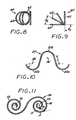
- a microcoil vaso-occlusive device Referring first to Figures 1-4 and 8 , a microcoil vaso-occlusive device
- the device 10 comprises a suitable length of wire formed into the primary configuration of a helical microcoil 12 ( Figure 2 ).
- Suitable materials for the device 10 include platinum, rhodium, palladium, rhenium, tungsten, gold, silver, tantalum, and various alloys of these metals.
- Various surgical grade stainless steels may also be used.
- Preferred materials include the platinum/tungsten alloy known as Platinum 479 (92% Pt, 8% W, available from Sigmund Cohn, of Mount Vernon, NY) and titanium/nickel alloys (such as the titanium/nickel alloy known as "nitinol").
- Platinum 479 92% Pt, 8% W, available from Sigmund Cohn, of Mount Vernon, NY
- titanium/nickel alloys such as the titanium/nickel alloy known as "nitinol”
- Another material that may be advantageous is a bimetallic wire comprising a highly elastic metal with a highly radiopaque metal.
- Such a bimetallic wire would also be resistant to permanent deformation.
- An example of such a bimetallic wire is a product comprising a nitinol outer layer and an inner core of pure reference grade platinum, available from Sigmund Cohn, of Mount Vernon, NY, and Anomet Products, of Shrewsbury, MA. Wire diameters of about 0.0125 mm to about 0.150 mm may be used.
- the microcoil 12 has a diameter that is typically in the range of about 0.125 mm to about 0.625 mm, with a preferred a preferred range, for most neurovascular applications, of about 0.25 mm to about 0.40 mm.
- the axial length of the microcoil 12 may be anywhere from about 5 mm to about 1000 mm, with about 20 mm to about 400 mm being typical.
- the primary winding of the microcoil 12 is applied under tension.
- the amount of tension, and the pitch of the primary winding determine the stiffness of the microcoil 12. These parameters can be varied along the length of the microcoil 12 to form a microcoil having different degrees of stiffness along its length, which may be advantageous in certain applications.
- the microcoil 12 is formed into a secondary configuration that comprises a plurality of curved segments, each defining an axis, whereby the microcoil 12 defines multiple axes. More specifically, each of the curved segments defines a plane an axis that is substantially perpendicular to the plane.
- the curved segments are tangentially-interconnected closed loops 14a, 14b that are substantially circular, and that define a plurality of separate axes 16.
- the loops 14a, 14b are substantially coplanar and define axes 16 that are substantially parallel.
- each pair of adjacent loops 14a, 14b defines a shallow angle, whereby their respective axes 16 define an angle ( ⁇ 1 , ⁇ 2 , ⁇ 3 , and ⁇ 4 ) of not more than about 90° between them, and preferably not more than about 45°.
- the device typically includes a pair of end loops 14a and at least one intermediate loop 14b.
- the intermediate loops are sized to have a diameter approximately equal to the maximum diameter of the target vascular site (e.g., an aneurysm), while the end loops 14a have a slightly smaller diameter (preferably, approximately 1.5 mm smaller), for purposes to be described below.
- the primary microcoil 12 is formed into the secondary configuration by heat treatment, as is well known in the art.
- the annealed primary coil may be initially placed into the secondary configuration by winding or wrapping around a suitably shaped and sized mandrel of refractory material, and then subjected to an annealing temperature for a specified period of time.
- an annealing temperature for example, an annealing temperature of about 500 ° C to about 1000°C, preferably approximately 670° C, is maintained for about 30 to 90 minutes, preferably about 60 minutes, then cooled to room temperature and ultrasonically cleaned.
- the resultant secondary configuration is thereby made permanent, and it becomes the minimum energy state configuration of the microcoil 12.
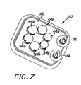
- FIG. 7 shows a heat treatment fixture 50 used in the manufacture of the preferred embodiment of the invention.
- the fixture 50 is made of a refractory material, and it includes a base 52 having a surface on which is provided a mandrel for the secondary winding.
- the mandrel comprises a plurality of winding pins 54a, 54b extending upwardly from the surface of the base 52.
- the exemplary fixture 50 shown in the drawing has six pins arranged in roughly a hexagonal pattern. There are two end winding pins 54a adjacent each other, and four intermediate winding pins 54b.
- a pair of fastening pegs 56 is located near one end of the fixture, for fastening the ends of the primary coil 12.
- the diameters of the end winding pins 54a are slightly smaller than the diameters of the intermediate winding pins 54b to achieve the size relationships described above.
- the spacings between the pins 54a, 54b are only slightly greater than the diameter of the primary coil 12, so that only one wind of the primary coil can be passed around the pins with each winding of the secondary coil.
- Each subsequent winding of the secondary coil is thus stacked on top of the previous winding. This eliminates any straight sections in the secondary coil, which, during deployment, would tend to push the coil into the parent artery.
- the primary coil 12 is kept under tension.
- the amount of tension can be adjusted to control the degree of spring-back of the loops 14a, 14b of the microcoil 12.
- the secondary winding of the microcoil 12 is performed so that the loops 14a, 14b reverse direction as the microcoil 12 is wrapped around each successive pin on the fixture. This ensures that loops will not coin stack, and that they will disperse randomly throughout the aneurysm once deployed. Furthermore, in the preferred embodiment, each loop is wound a complete 360° before the next loop is wound. This ensures that each loop will completely seat within the aneurysm before the microcoil 12 reverses direction. With a complete loop intact, the loop strength is maximized, and the loop distributes loads evenly.
- Figures 12-15 and 17 illustrate alternative forms of the above-described device.
- a microcoil 12' has a secondary configuration that includes a plurality of connected curved segments, wherein the curved segments are overlapping connected closed loops 14', that are substantially circular, with each loop 14' defining a separate axis 16'.
- a microcoil 12" has a secondary configuration that includes a plurality of connected curved segments, wherein the curved segments are tangentially-interconnected, substantially elliptical loops 14", each defining a separate axis 16".
- Figures 14 and 15 show alternative forms that are similar to that of Figures 1-4 , except that the loops are of different diameters.
- a microcoil 12"' has a secondary configuration that includes a plurality of tangentially-interconnected, substantially circular loops 14"' of progressively decreasing diameter, starting from a loop 14"'c of the largest diameter, each of the loops defining a unique axis 16"'.
- the variant form shown in Figure 15 is similar to that of Figure 14 , except that there is an additional small-diameter loop 14"'d preceding the largest diameter loop 14"'c.
- the inventive device illustrated in Figure 17 comprises a microcoil 12 iv having a minimum energy state secondary configuration in which a plurality of interconnected, tangential loops 14 iv are arranged so that each loop defines an axis 16 iv that is orthogonal to a unique radius r of a circle, the radii being separated by a fixed angle of arc ⁇ .
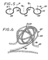
- Figure 5 shows a microcoil vaso-occlusion device 20.
- This embodiment includes a primary microcoil 22 formed into a secondary minimum energy state configuration that defines a wave-form like structure comprising a longitudinal array of laterally-alternating open loops 24 defining a plurality of separate axes 26.
- the device may be in a first form in which the loops 24 are substantially coplanar and their respective axes 26 are substantially parallel, or in a second form in which each pair of adjacent loops 24 defines a shallow angle, whereby their respective axes 26 define an angle of not more than about 90°, and preferably not more than about 45°, between them.
- the materials, dimensions, and method of manufacture of this device are, in all material respects, similar to those of the device described above.
- Figure 10 illustrates a specific construction of this device, wherein the primary microcoil structure 22' is formed into a secondary minimum energy state configuration having a wave-form like structure that defines a substantially sinusoidal waveform, defining a plurality of separate axes 26'.
- the waveform has at least one maximum 22a and at least one minimum 22b, each of which defines an arc of radius r, and wherein each arc is connected to an adjacent arc by a straight section of length L, wherein L is less than about 2r.
- the proximal end of the microcoil 12 (or 22) is attached to the distal end of an elongate delivery device, such as a guidewire or microcatheter (not shown).
- the attachment may be by any of a number of ways known in the art, as exemplified by the following U.S. patents, the disclosures of which are expressly incorporated herein by reference: 5,108,407 - Geremia et al. ; 5,122,136 - Guglielmi et al. ; 5,234,437 - Sepetka ; 5,261,916 - Engelson ; 5,304,195 - Twyford, Jr. et al.
- a target vascular site is visualized, by conventional means, well-known in the art.
- the target vascular site may be an aneurysm 40 branching off a parent artery 42.
- the aneurysm 40 has a dome 44 connected to the branch artery by a neck 46.
- a catheter 30 is passed intravascularly until it enters the dome 44 of the aneurysm 40 via the neck 46.
- the microcoil 12 is passed through the catheter 30 with the assistance of the guidewire or microcatheter until the microcoil 12 enters the dome 44 of the aneurysm 40.
- the undersized end loop 14a at the distal end of the microcoil 12 enters the aneurysm first. This assists in seating the first loop properly, because the smaller size keeps the first loop inside the neck 46 of the aneurysm, avoiding the parent artery 42.
- the intermediate loops 14b then enter the aneurysm. Because they are sized to fit the aneurysm, they can deploy freely and smoothly with minimal friction against the wall of the aneurysm. Because the secondary configuration of the microcoil 12 is essentially coplanar, all of the intermediate loops exert a force against the walls of the aneurysm dome 44, thereby improving the resistance of the microcoil 12 to shifting due to pulsatile blood flow.
- the microcoil 12 As the microcoil 12 enters the aneurysm, it attempts to assume its secondary configuration. Because the microcoil, in its secondary configuration, is larger than the aneurysm, however, it is constrained into a deployed configuration in which it tends to line the periphery of the aneurysm. In this deployed configuration, the microcoil is in an energy state that is substantially higher than its minimum energy state. Thus, when the device is deployed inside a vascular site such as an aneurysm, the confinement of the device within the site causes the device to assume a three-dimensional configuration that has a higher energy state than the minimum energy state.
- the minimum energy state of the device is larger (in at least one dimension) than the space in which it is deployed, the deployed device is constrained by its intimate contact with the walls of the aneurysm from returning to its minimum energy state configuration. Therefore, the device still engages the surrounding aneurysm wall surface, thereby minimizing shifting or tumbling due to blood flow dynamics. Furthermore, the minimum energy state secondary configuration (to which the device attempts to revert) is not one that is conducive to "coin stacking", thereby minimizing the degree of compaction that is experienced. -
- the microcoil is designed with a maximum loops diameter that is dimensioned to line the periphery of the aneurysm upon deployment, as mentioned above. For larger aneurysms, it is advantageous to fill in a substantial portion of the interior volume of the aneurysm by deploying one or more additional microcoils, of progressively smaller maximum loop diameter.
- FIGS 8 and 9 illustrate a further vaso-occlusion device.
- This embodiment includes a primary microcoil 60 formed into a secondary minimum energy state configuration that forms a series of tangential closed loops 62 (preferably substantially circular or elliptical), wherein the entire structure subtends a first angle of arc ⁇ 1 , and wherein each adjacent pair of circles or ellipses defines a second angle of arc ⁇ 2 between them.
- the first angle ⁇ 1 is greater than about 30°
- the second angle ⁇ 2 is less than about half of the first angle ⁇ 1 .
- each loop 62 defines an axis, whereby the angle formed between the axes of adjacent loops 62 is equal to ⁇ 2 .
- Figure 11 illustrates a further vaso-occlusive device.
- a microcoil 70 has a secondary configuration that forms at least a pair of connected equiangular or logarithmic spirals 72, each of the spirals defining an axis 73 that is orthogonal to the plane defined by the spiral.
- an equiangular or logarithmic spiral is defined as a curve that cuts all radii vectors at a constant angle, where a radial vector R is defined as a line drawn from any point P on the spiral to the center of the spiral.
- the spiral will be an equiangular spiral if the angle ⁇ formed between a radial vector and the tangent for any point P on the spiral is constant.
- Figure 16 illustrates a further vaso-occlusive device, wherein a microcoil 80 has a secondary configuration that resembles a series of interconnected complex curved segments 82, each of which is defined by a path around the surface of a sphere 84. Each of the segments is thus defined by a unique focus 86 located at the approximate center point of the sphere 84 around which the path is generated, and by a radius r extending from that locus 86 that is equal to the radius of that sphere.
- Each segment may be defined by radii that are coplanar (in the case of a segment that is defined by a substantially circumferential path around its defining sphere), or by radii that lie in different planes intersecting the sphere (where path around the defining sphere deviates from a circumferential path).
- the segments thus resemble nearly, but not fully, completed circles (circumferential path) or helical loops (non-circumferential path), and they may be either of uniform or different diameters.
- the present invention thus exhibits several advantages over prior art three-dimensional microcoils. For example, there is increased coverage of the aneurysm neck, due to the presence of loops across the neck, yet the probability of any part of the device intruding into the parent artery is reduced.
- the secondary coil configuration also provides smoother deployment, and, once deployed, the device exhibits greater resistance to coil compaction, thereby increasing positional stability in the face of pulsatile blood flow. This stability is achieved with lower overall friction between the device and the aneurysm wall.
- the random distribution of loops throughout the aneurysm allows the device to maintain a complex shape inside the aneurysm, yielding improved embolization.
Landscapes
- Health & Medical Sciences (AREA)
- Surgery (AREA)
- Life Sciences & Earth Sciences (AREA)
- Biomedical Technology (AREA)
- Medical Informatics (AREA)
- Vascular Medicine (AREA)
- Reproductive Health (AREA)
- Engineering & Computer Science (AREA)
- Veterinary Medicine (AREA)
- Heart & Thoracic Surgery (AREA)
- Nuclear Medicine, Radiotherapy & Molecular Imaging (AREA)
- Molecular Biology (AREA)
- Animal Behavior & Ethology (AREA)
- General Health & Medical Sciences (AREA)
- Public Health (AREA)
- Neurosurgery (AREA)
- Surgical Instruments (AREA)
Abstract
Claims (10)
- Dispositif vaso-occlusif (10, 20) comprenant un élément filamenteux formé pour constituer une configuration d'un état d'énergie minimale comprenant une série d'au moins trois boucles interconnectées de manière tangentielle (14a, 14b), chacune desdites boucles de la série d'au moins trois boucles définissant un axe (16) qui est orthogonal à un rayon unique d'un cercle, des rayons adjacents étant séparés par un angle fixé d'arc (Θ), caractérisé en ce que chacune desdites boucles (14a, 14b) de la série d'au moins trois boucles étant formées par l'enroulage de l'élément filamenteux autour de l'axe respectif (16) de chaque boucle dans des directions alternantes,
- Dispositif selon la revendication 1, dans lequel au moins l'une des boucles (14') recouvre une boucle adjacente.
- Dispositif selon la revendication 1, dans lequel le dispositif comprend une pluralité de boucles (14"') d'un diamètre diminuant progressivement à partir d'une boucle maximale (1A"'c) à une boucle minimale.
- Dispositif selon la revendication 3, dans lequel la boucle minimale est une première boucle minimale, et dans lequel le dispositif comprend en outre une deuxième boucle minimale immédiatement adjacente à la boucle maximale (14"'c).
- Dispositif vaso-occlusif selon la revendication 1, dans lequel la microbobine forme une structure tridimensionnelle allongée.
- Dispositif vaso-occlusif selon la revendication 1, dans lequel au moins deux boucles adjacentes de la série d'au moins trois boucles sont formées de manière à ce qu'il n'y a pas de sections droites de microbobine entre les boucles adjacentes.
- Dispositif vaso-occlusif selon la revendication 1, dans lequel chacune des boucles de la série d'au moins trois boucles définit un plan différent.
- Dispositif vaso-occlusif selon la revendication 1, dans lequel les plans définis par au moins deux boucles adjacentes de la série d'au moins trois boucles définissent un angle de 90 degrés.
- Dispositif vaso-occlusif selon la revendication 1, dans lequel les plans définis par au moins deux boucles adjacentes de la série d'au moins trois boucles définissent un angle supérieur à 90 degrés.
- Dispositif vaso-occlusif selon la revendication 1, dans lequel au moins deux boucles adjacentes ont des diamètres maximales différents.
Priority Applications (2)
| Application Number | Priority Date | Filing Date | Title |
|---|---|---|---|
| EP11165088A EP2363081A1 (fr) | 2002-01-11 | 2003-01-10 | Dispositif vaso-occlusif à micro-bobine avec configuration secondaire multiaxes |
| EP11165090.9A EP2353523B1 (fr) | 2002-01-11 | 2003-01-10 | Dispositif vaso-occlusif à micro-bobine avec configuration secondaire multiaxes |
Applications Claiming Priority (3)
| Application Number | Priority Date | Filing Date | Title |
|---|---|---|---|
| US43947 | 2002-01-11 | ||
| US10/043,947 US7033374B2 (en) | 2000-09-26 | 2002-01-11 | Microcoil vaso-occlusive device with multi-axis secondary configuration |
| PCT/US2003/000779 WO2003059176A2 (fr) | 2002-01-11 | 2003-01-10 | Dispositif vaso-occlusif a microbobine et a configuration multi-axe secondaire |
Related Child Applications (3)
| Application Number | Title | Priority Date | Filing Date |
|---|---|---|---|
| EP11165090.9A Division EP2353523B1 (fr) | 2002-01-11 | 2003-01-10 | Dispositif vaso-occlusif à micro-bobine avec configuration secondaire multiaxes |
| EP11165090.9 Division-Into | 2011-05-06 | ||
| EP11165088.3 Division-Into | 2011-05-06 |
Publications (2)
| Publication Number | Publication Date |
|---|---|
| EP1467663A2 EP1467663A2 (fr) | 2004-10-20 |
| EP1467663B1 true EP1467663B1 (fr) | 2012-06-20 |
Family
ID=21929738
Family Applications (3)
| Application Number | Title | Priority Date | Filing Date |
|---|---|---|---|
| EP11165090.9A Expired - Lifetime EP2353523B1 (fr) | 2002-01-11 | 2003-01-10 | Dispositif vaso-occlusif à micro-bobine avec configuration secondaire multiaxes |
| EP11165088A Withdrawn EP2363081A1 (fr) | 2002-01-11 | 2003-01-10 | Dispositif vaso-occlusif à micro-bobine avec configuration secondaire multiaxes |
| EP03707353A Expired - Lifetime EP1467663B1 (fr) | 2002-01-11 | 2003-01-10 | Dispositif vaso-occlusif a microbobine et a configuration multi-axe secondaire |
Family Applications Before (2)
| Application Number | Title | Priority Date | Filing Date |
|---|---|---|---|
| EP11165090.9A Expired - Lifetime EP2353523B1 (fr) | 2002-01-11 | 2003-01-10 | Dispositif vaso-occlusif à micro-bobine avec configuration secondaire multiaxes |
| EP11165088A Withdrawn EP2363081A1 (fr) | 2002-01-11 | 2003-01-10 | Dispositif vaso-occlusif à micro-bobine avec configuration secondaire multiaxes |
Country Status (6)
| Country | Link |
|---|---|
| US (2) | US7033374B2 (fr) |
| EP (3) | EP2353523B1 (fr) |
| JP (2) | JP2005514978A (fr) |
| AU (1) | AU2003209206A1 (fr) |
| ES (1) | ES2389650T3 (fr) |
| WO (1) | WO2003059176A2 (fr) |
Families Citing this family (97)
| Publication number | Priority date | Publication date | Assignee | Title |
|---|---|---|---|---|
| FR2768324B1 (fr) | 1997-09-12 | 1999-12-10 | Jacques Seguin | Instrument chirurgical permettant, par voie percutanee, de fixer l'une a l'autre deux zones de tissu mou, normalement mutuellement distantes |
| ATE492219T1 (de) | 1999-04-09 | 2011-01-15 | Evalve Inc | Vorrichtung zur herzklappenoperation |
| US20040044350A1 (en) | 1999-04-09 | 2004-03-04 | Evalve, Inc. | Steerable access sheath and methods of use |
| US8216256B2 (en) | 1999-04-09 | 2012-07-10 | Evalve, Inc. | Detachment mechanism for implantable fixation devices |
| US7811296B2 (en) | 1999-04-09 | 2010-10-12 | Evalve, Inc. | Fixation devices for variation in engagement of tissue |
| US6752813B2 (en) | 1999-04-09 | 2004-06-22 | Evalve, Inc. | Methods and devices for capturing and fixing leaflets in valve repair |
| US7226467B2 (en) | 1999-04-09 | 2007-06-05 | Evalve, Inc. | Fixation device delivery catheter, systems and methods of use |
| US7604646B2 (en) | 1999-04-09 | 2009-10-20 | Evalve, Inc. | Locking mechanisms for fixation devices and methods of engaging tissue |
| EP1867300A3 (fr) * | 1999-06-02 | 2008-02-27 | Sethel Interventional, Inc. | Dispositif intracorporel occlusif |
| US7033374B2 (en) * | 2000-09-26 | 2006-04-25 | Microvention, Inc. | Microcoil vaso-occlusive device with multi-axis secondary configuration |
| US7029486B2 (en) * | 2000-09-26 | 2006-04-18 | Microvention, Inc. | Microcoil vaso-occlusive device with multi-axis secondary configuration |
| US6605101B1 (en) * | 2000-09-26 | 2003-08-12 | Microvention, Inc. | Microcoil vaso-occlusive device with multi-axis secondary configuration |
| US7048754B2 (en) * | 2002-03-01 | 2006-05-23 | Evalve, Inc. | Suture fasteners and methods of use |
| DE03764480T1 (de) * | 2002-07-12 | 2005-10-20 | Cook Urological Inc | Flexibler kanülenstiel |
| US10631871B2 (en) | 2003-05-19 | 2020-04-28 | Evalve, Inc. | Fixation devices, systems and methods for engaging tissue |
| US20050159676A1 (en) * | 2003-08-13 | 2005-07-21 | Taylor James D. | Targeted biopsy delivery system |
| US7485123B2 (en) | 2004-03-01 | 2009-02-03 | Boston Scientific Scimed, Inc. | Complex vaso-occlusive coils |
| US7488332B2 (en) * | 2004-03-01 | 2009-02-10 | Boston Scientific Scimed, Inc. | Vaso-occlusive coils with non-overlapping sections |
| US8845676B2 (en) | 2004-09-22 | 2014-09-30 | Micro Therapeutics | Micro-spiral implantation device |
| ES2321300T3 (es) | 2004-09-22 | 2009-06-04 | Dendron Gmbh | Implante medico. |
| US8052592B2 (en) | 2005-09-27 | 2011-11-08 | Evalve, Inc. | Methods and devices for tissue grasping and assessment |
| CA2581852C (fr) | 2004-09-27 | 2012-11-13 | Evalve, Inc. | Procedes et dispositifs de saisie et d'evaluation de tissus |
| WO2006053107A1 (fr) * | 2004-11-09 | 2006-05-18 | Boston Scientific Limited | Dispositifs vaso-occlusifs presentant une partie proximale de forme complexe et une partie distale a diametre inferieur |
| US8545530B2 (en) * | 2005-10-19 | 2013-10-01 | Pulsar Vascular, Inc. | Implantable aneurysm closure systems and methods |
| BRPI0617652A2 (pt) | 2005-10-19 | 2011-08-02 | Pulsar Vascular Inc | métodos e sistemas para incisão endovascular e reparo de defeitos de tecido e lúmen |
| JP5154432B2 (ja) * | 2005-11-17 | 2013-02-27 | マイクロベンション インコーポレイテッド | 三次元コンプレックスコイル |
| EP1959873B1 (fr) | 2005-12-13 | 2015-05-20 | Codman & Shurtleff, Inc. | Actionneur de detachement a utiliser avec des systemes de deploiement de dispositif medical |
| US8777979B2 (en) | 2006-04-17 | 2014-07-15 | Covidien Lp | System and method for mechanically positioning intravascular implants |
| US8864790B2 (en) | 2006-04-17 | 2014-10-21 | Covidien Lp | System and method for mechanically positioning intravascular implants |
| CN101500623B (zh) | 2006-06-15 | 2016-08-24 | 微温森公司 | 一种由可膨胀聚合物构成的栓塞器械 |
| US8062325B2 (en) * | 2006-07-31 | 2011-11-22 | Codman & Shurtleff, Inc. | Implantable medical device detachment system and methods of using the same |
| US8366720B2 (en) * | 2006-07-31 | 2013-02-05 | Codman & Shurtleff, Inc. | Interventional medical device system having an elongation retarding portion and method of using the same |
| US7708704B2 (en) * | 2006-07-31 | 2010-05-04 | Codman & Shurtleff, Pc | Interventional medical device component having an interrupted spiral section and method of making the same |
| JP5227344B2 (ja) * | 2007-03-13 | 2013-07-03 | タイコ ヘルスケア グループ リミテッド パートナーシップ | インプラント、マンドレル、およびインプラント形成方法 |
| JP5249249B2 (ja) | 2007-03-13 | 2013-07-31 | コヴィディエン リミテッド パートナーシップ | コイルと耐伸張性部材とが含まれているインプラント |
| US20080319527A1 (en) * | 2007-06-22 | 2008-12-25 | Lee Jeffrey A | Shaped multi-durometer filler |
| WO2009086214A1 (fr) | 2007-12-21 | 2009-07-09 | Microvention, Inc. | Système et procédé de détection de détachement d'implant |
| JP5366974B2 (ja) | 2007-12-21 | 2013-12-11 | マイクロベンション インコーポレイテッド | 分離可能なインプラントの分離域の位置を決定するシステムおよび方法 |
| EP2266639B1 (fr) | 2007-12-21 | 2016-10-05 | MicroVention, Inc. | Méthodes de préparation de filaments d'hydrogel pour utilisations biomédicales |
| US10028747B2 (en) | 2008-05-01 | 2018-07-24 | Aneuclose Llc | Coils with a series of proximally-and-distally-connected loops for occluding a cerebral aneurysm |
| US10716573B2 (en) | 2008-05-01 | 2020-07-21 | Aneuclose | Janjua aneurysm net with a resilient neck-bridging portion for occluding a cerebral aneurysm |
| EP2326259B1 (fr) | 2008-09-05 | 2021-06-23 | Pulsar Vascular, Inc. | Systèmes pour soutenir ou fermer une ouverture ou cavité physiologique |
| US10639396B2 (en) | 2015-06-11 | 2020-05-05 | Microvention, Inc. | Polymers |
| ES2922979T3 (es) | 2009-09-04 | 2022-09-22 | Pulsar Vascular Inc | Sistemas para encerrar una abertura anatómica |
| EP2480166B1 (fr) | 2009-09-24 | 2017-11-29 | Microvention, Inc. | Filaments d'hydrogel injectable pour des utilisations biomédicales |
| EP2493367B1 (fr) * | 2009-10-26 | 2019-03-13 | Microvention, Inc. | Dispositif d'embolisation construit à partir d'un polymère expansible |
| JP5512238B2 (ja) * | 2009-11-13 | 2014-06-04 | 株式会社カネカ | 生体内留置部材の製造方法 |
| US9358140B1 (en) | 2009-11-18 | 2016-06-07 | Aneuclose Llc | Stent with outer member to embolize an aneurysm |
| KR20130054952A (ko) | 2010-04-14 | 2013-05-27 | 마이크로벤션, 인코포레이티드 | 임플란트 전달 장치 |
| WO2012145431A2 (fr) | 2011-04-18 | 2012-10-26 | Microvention, Inc. | Dispositifs d'embolisation |
| KR102019025B1 (ko) | 2011-06-03 | 2019-09-06 | 펄사 배스큘라, 아이엔씨. | 해부학적 구멍을 둘러싸기 위한 시스템 및 방법, 가령, 충격 흡수 동맥류 장치 |
| CN103582460B (zh) | 2011-06-03 | 2019-03-19 | 帕尔萨维斯库勒公司 | 具有额外锚固机构的动脉瘤装置以及相关系统及方法 |
| US8945177B2 (en) | 2011-09-13 | 2015-02-03 | Abbott Cardiovascular Systems Inc. | Gripper pusher mechanism for tissue apposition systems |
| EP2763602B1 (fr) | 2011-10-05 | 2020-07-01 | Pulsar Vascular, Inc. | Dispositifs et systèmes pour enfermer une ouverture anatomique |
| US9579104B2 (en) | 2011-11-30 | 2017-02-28 | Covidien Lp | Positioning and detaching implants |
| US9011480B2 (en) | 2012-01-20 | 2015-04-21 | Covidien Lp | Aneurysm treatment coils |
| US9687245B2 (en) | 2012-03-23 | 2017-06-27 | Covidien Lp | Occlusive devices and methods of use |
| WO2013158781A1 (fr) | 2012-04-18 | 2013-10-24 | Microvention, Inc. | Dispositifs emboliques |
| JP6411331B2 (ja) | 2012-05-10 | 2018-10-24 | パルサー バスキュラー インコーポレイテッド | コイル付き動脈瘤装置 |
| JP6119749B2 (ja) * | 2012-06-29 | 2017-04-26 | 株式会社カネカ | 生体内留置部材の製造方法 |
| JP6046444B2 (ja) * | 2012-10-24 | 2016-12-14 | 株式会社カネカ | 生体内留置用二次コイルおよびその製造方法 |
| CN105899150B (zh) | 2013-07-31 | 2018-07-27 | Neuvt 有限公司 | 用于血管内栓塞的方法和装置 |
| US10010328B2 (en) | 2013-07-31 | 2018-07-03 | NeuVT Limited | Endovascular occlusion device with hemodynamically enhanced sealing and anchoring |
| WO2015100297A1 (fr) * | 2013-12-26 | 2015-07-02 | Stryker Corporation | Bobine vaso-occlusive pourvue de segments flexibles |
| JP6566961B2 (ja) | 2014-02-27 | 2019-08-28 | インキュメデックス インコーポレイテッド | 塞栓骨組マイクロコイル |
| US10390943B2 (en) | 2014-03-17 | 2019-08-27 | Evalve, Inc. | Double orifice device for transcatheter mitral valve replacement |
| US10124090B2 (en) | 2014-04-03 | 2018-11-13 | Terumo Corporation | Embolic devices |
| US9713475B2 (en) | 2014-04-18 | 2017-07-25 | Covidien Lp | Embolic medical devices |
| US10092663B2 (en) | 2014-04-29 | 2018-10-09 | Terumo Corporation | Polymers |
| JP6599361B2 (ja) | 2014-04-29 | 2019-10-30 | マイクロベンション インコーポレイテッド | 活性剤を含むポリマー |
| US20150327868A1 (en) * | 2014-05-13 | 2015-11-19 | Ndi Tip Teknolojileri Anonim Sirketi | Retractable and rapid disconnect, floating diameter embolic coil product and delivery system |
| US10188392B2 (en) | 2014-12-19 | 2019-01-29 | Abbott Cardiovascular Systems, Inc. | Grasping for tissue repair |
| US10595875B2 (en) | 2014-12-31 | 2020-03-24 | Endostream Medical Ltd. | Device for restricting blood flow to aneurysms |
| US10524912B2 (en) | 2015-04-02 | 2020-01-07 | Abbott Cardiovascular Systems, Inc. | Tissue fixation devices and methods |
| US10376673B2 (en) | 2015-06-19 | 2019-08-13 | Evalve, Inc. | Catheter guiding system and methods |
| US10238494B2 (en) | 2015-06-29 | 2019-03-26 | Evalve, Inc. | Self-aligning radiopaque ring |
| US10667815B2 (en) | 2015-07-21 | 2020-06-02 | Evalve, Inc. | Tissue grasping devices and related methods |
| US10413408B2 (en) | 2015-08-06 | 2019-09-17 | Evalve, Inc. | Delivery catheter systems, methods, and devices |
| US10307168B2 (en) | 2015-08-07 | 2019-06-04 | Terumo Corporation | Complex coil and manufacturing techniques |
| US10238495B2 (en) | 2015-10-09 | 2019-03-26 | Evalve, Inc. | Delivery catheter handle and methods of use |
| WO2017086479A1 (fr) * | 2015-11-19 | 2017-05-26 | 株式会社カネカ | Élément à demeure in vivo, et dispositif de placement d'élément à demeure in vivo comprenant ledit élément à demeure in vivo |
| US10966728B2 (en) * | 2016-06-21 | 2021-04-06 | Endostream Medical Ltd. | Medical device for treating vascular malformations |
| US10736632B2 (en) | 2016-07-06 | 2020-08-11 | Evalve, Inc. | Methods and devices for valve clip excision |
| US11071564B2 (en) | 2016-10-05 | 2021-07-27 | Evalve, Inc. | Cardiac valve cutting device |
| US10363138B2 (en) | 2016-11-09 | 2019-07-30 | Evalve, Inc. | Devices for adjusting the curvature of cardiac valve structures |
| US10398553B2 (en) | 2016-11-11 | 2019-09-03 | Evalve, Inc. | Opposing disk device for grasping cardiac valve tissue |
| US10426616B2 (en) | 2016-11-17 | 2019-10-01 | Evalve, Inc. | Cardiac implant delivery system |
| US10779837B2 (en) | 2016-12-08 | 2020-09-22 | Evalve, Inc. | Adjustable arm device for grasping tissues |
| US10314586B2 (en) | 2016-12-13 | 2019-06-11 | Evalve, Inc. | Rotatable device and method for fixing tricuspid valve tissue |
| WO2018209313A1 (fr) | 2017-05-12 | 2018-11-15 | Evalve, Inc. | Pince de réparation de valvule à bras long |
| US9848906B1 (en) | 2017-06-20 | 2017-12-26 | Joe Michael Eskridge | Stent retriever having an expandable fragment guard |
| US10912569B2 (en) | 2018-08-22 | 2021-02-09 | Covidien Lp | Aneurysm treatment coils and associated systems and methods of use |
| US10905432B2 (en) * | 2018-08-22 | 2021-02-02 | Covidien Lp | Aneurysm treatment coils and associated systems and methods of use |
| US20220087680A1 (en) * | 2018-12-26 | 2022-03-24 | Endostream Medical Ltd. | Devices for treating vascular malformations |
| WO2020148768A1 (fr) | 2019-01-17 | 2020-07-23 | Endostream Medical Ltd. | Système d'implant de malformation vasculaire |
| US11399840B2 (en) | 2019-08-13 | 2022-08-02 | Covidien Lp | Implantable embolization device |
| CN114615940A (zh) * | 2019-09-13 | 2022-06-10 | 阿万泰血管公司 | 血管内线圈及其制造方法 |
Citations (1)
| Publication number | Priority date | Publication date | Assignee | Title |
|---|---|---|---|---|
| WO1999009893A1 (fr) * | 1997-08-29 | 1999-03-04 | Boston Scientific Limited | Dispositif vaso-occlusif de forme anatomique et son procede de fabrication |
Family Cites Families (143)
| Publication number | Priority date | Publication date | Assignee | Title |
|---|---|---|---|---|
| US407818A (en) * | 1889-07-30 | Island | ||
| US421304A (en) * | 1890-02-11 | Teollet for electric railways | ||
| CS154391B1 (fr) * | 1970-09-10 | 1974-04-30 | ||
| US4017911A (en) * | 1974-05-28 | 1977-04-19 | American Hospital Supply Corporation | Heart valve with a sintered porous surface |
| US4374669A (en) * | 1975-05-09 | 1983-02-22 | Mac Gregor David C | Cardiovascular prosthetic devices and implants with porous systems |
| US4509504A (en) * | 1978-01-18 | 1985-04-09 | Medline Ab | Occlusion of body channels |
| HU184722B (en) * | 1980-02-18 | 1984-10-29 | Laszlo Lazar | Therapeutically suitable silicone rubber mixture and therapeuticaid |
| EP0054781B1 (fr) * | 1980-12-23 | 1984-10-10 | Kontron Ag | Electrode implantable |
| US4493329A (en) * | 1982-08-19 | 1985-01-15 | Lynn Crawford | Implantable electrode having different stiffening and curvature maintaining characteristics along its length |
| US4512338A (en) * | 1983-01-25 | 1985-04-23 | Balko Alexander B | Process for restoring patency to body vessels |
| US4808155A (en) * | 1986-02-27 | 1989-02-28 | Mahurkar Sakharam D | Simple double lumen catheter |
| US4739768B2 (en) * | 1986-06-02 | 1995-10-24 | Target Therapeutics Inc | Catheter for guide-wire tracking |
| US4795741A (en) * | 1987-05-06 | 1989-01-03 | Biomatrix, Inc. | Compositions for therapeutic percutaneous embolization and the use thereof |
| US4819637A (en) * | 1987-09-01 | 1989-04-11 | Interventional Therapeutics Corporation | System for artificial vessel embolization and devices for use therewith |
| US4994069A (en) * | 1988-11-02 | 1991-02-19 | Target Therapeutics | Vaso-occlusion coil and method |
| US5289831A (en) * | 1989-03-09 | 1994-03-01 | Vance Products Incorporated | Surface-treated stent, catheter, cannula, and the like |
| US5304121A (en) * | 1990-12-28 | 1994-04-19 | Boston Scientific Corporation | Drug delivery system making use of a hydrogel polymer coating |
| US6083220A (en) * | 1990-03-13 | 2000-07-04 | The Regents Of The University Of California | Endovascular electrolytically detachable wire and tip for the formation of thrombus in arteries, veins, aneurysms, vascular malformations and arteriovenous fistulas |
| US5122136A (en) * | 1990-03-13 | 1992-06-16 | The Regents Of The University Of California | Endovascular electrolytically detachable guidewire tip for the electroformation of thrombus in arteries, veins, aneurysms, vascular malformations and arteriovenous fistulas |
| US5108407A (en) * | 1990-06-08 | 1992-04-28 | Rush-Presbyterian St. Luke's Medical Center | Method and apparatus for placement of an embolic coil |
| US5133731A (en) * | 1990-11-09 | 1992-07-28 | Catheter Research, Inc. | Embolus supply system and method |
| US6524274B1 (en) * | 1990-12-28 | 2003-02-25 | Scimed Life Systems, Inc. | Triggered release hydrogel drug delivery system |
| DE4104702C2 (de) * | 1991-02-15 | 1996-01-18 | Malte Neuss | Implantate für Organwege in Wendelform |
| US5304194A (en) * | 1991-10-02 | 1994-04-19 | Target Therapeutics | Vasoocclusion coil with attached fibrous element(s) |
| US5226911A (en) * | 1991-10-02 | 1993-07-13 | Target Therapeutics | Vasoocclusion coil with attached fibrous element(s) |
| JP3356447B2 (ja) * | 1991-10-16 | 2002-12-16 | テルモ株式会社 | 乾燥高分子ゲルからなる血管病変塞栓材料 |
| US5261916A (en) * | 1991-12-12 | 1993-11-16 | Target Therapeutics | Detachable pusher-vasoocclusive coil assembly with interlocking ball and keyway coupling |
| CA2084524C (fr) | 1991-12-12 | 1996-07-23 | Robert H. Twyford, Jr. | Dispositif d'avance helicoidal, avec accouplement a verrouillage, pour le traitement de l'occlusion vasculaire |
| US5234437A (en) * | 1991-12-12 | 1993-08-10 | Target Therapeutics, Inc. | Detachable pusher-vasoocclusion coil assembly with threaded coupling |
| US5527338A (en) * | 1992-09-02 | 1996-06-18 | Board Of Regents, The University Of Texas System | Intravascular device |
| US5350397A (en) * | 1992-11-13 | 1994-09-27 | Target Therapeutics, Inc. | Axially detachable embolic coil assembly |
| USRE37117E1 (en) * | 1992-09-22 | 2001-03-27 | Target Therapeutics, Inc. | Detachable embolic coil assembly using interlocking clasps and method of use |
| US5312415A (en) * | 1992-09-22 | 1994-05-17 | Target Therapeutics, Inc. | Assembly for placement of embolic coils using frictional placement |
| US5382259A (en) * | 1992-10-26 | 1995-01-17 | Target Therapeutics, Inc. | Vasoocclusion coil with attached tubular woven or braided fibrous covering |
| US5382260A (en) * | 1992-10-30 | 1995-01-17 | Interventional Therapeutics Corp. | Embolization device and apparatus including an introducer cartridge and method for delivering the same |
| US5690666A (en) * | 1992-11-18 | 1997-11-25 | Target Therapeutics, Inc. | Ultrasoft embolism coils and process for using them |
| JPH08500273A (ja) | 1992-11-19 | 1996-01-16 | ターゲット セラピューティクス,インコーポレイテッド | 大直径血管閉塞コイル |
| US5291916A (en) * | 1992-12-28 | 1994-03-08 | Excel Industries, Inc. | Check valve |
| WO1994021324A1 (fr) * | 1993-03-23 | 1994-09-29 | Focal, Inc. | Appareil et procede d'application locale d'un materiau polymere sur des tissus |
| US5800453A (en) | 1993-04-19 | 1998-09-01 | Target Therapeutics, Inc. | Detachable embolic coil assembly using interlocking hooks and slots |
| US5381259A (en) * | 1993-10-14 | 1995-01-10 | Xerox Corporation | Raster output scanner (ROS) using an overfilled polygon design with minimized optical path length |
| US5423829A (en) * | 1993-11-03 | 1995-06-13 | Target Therapeutics, Inc. | Electrolytically severable joint for endovascular embolic devices |
| US5381260A (en) * | 1993-11-19 | 1995-01-10 | The United States Of America As Represented By The Secretary Of The Army | Uniaxially strained semiconductor multiple quantum well device using direction-dependent thermal expansion coefficients in a host substrate |
| WO1995025480A1 (fr) * | 1994-03-18 | 1995-09-28 | Cook Incorporated | Spirale hélicoïdale d'embolisation |
| US5483022A (en) * | 1994-04-12 | 1996-01-09 | Ventritex, Inc. | Implantable conductor coil formed from cabled composite wire |
| JP2535785B2 (ja) * | 1994-06-03 | 1996-09-18 | 工業技術院長 | 血管塞栓剤 |
| US5725546A (en) | 1994-06-24 | 1998-03-10 | Target Therapeutics, Inc. | Detachable microcoil delivery catheter |
| US5549624A (en) * | 1994-06-24 | 1996-08-27 | Target Therapeutics, Inc. | Fibered vasooclusion coils |
| US5522836A (en) | 1994-06-27 | 1996-06-04 | Target Therapeutics, Inc. | Electrolytically severable coil assembly with movable detachment point |
| US5728079A (en) * | 1994-09-19 | 1998-03-17 | Cordis Corporation | Catheter which is visible under MRI |
| US5690671A (en) | 1994-12-13 | 1997-11-25 | Micro Interventional Systems, Inc. | Embolic elements and methods and apparatus for their delivery |
| US5578074A (en) * | 1994-12-22 | 1996-11-26 | Target Therapeutics, Inc. | Implant delivery method and assembly |
| US5814062A (en) * | 1994-12-22 | 1998-09-29 | Target Therapeutics, Inc. | Implant delivery assembly with expandable coupling/decoupling mechanism |
| JP3625837B2 (ja) * | 1995-01-27 | 2005-03-02 | シメッド ライフ システムズ,インコーポレイテッド | 塞栓装置 |
| USD407818S (en) * | 1995-03-31 | 1999-04-06 | Target Therapeutics, Inc. | Spiral vaso-occlusion coil |
| US6171326B1 (en) * | 1998-08-27 | 2001-01-09 | Micrus Corporation | Three dimensional, low friction vasoocclusive coil, and method of manufacture |
| US5911731A (en) * | 1995-04-20 | 1999-06-15 | Target Therapeutics, Inc. | Anatomically shaped vasoocclusive devices |
| US5645558A (en) * | 1995-04-20 | 1997-07-08 | Medical University Of South Carolina | Anatomically shaped vasoocclusive device and method of making the same |
| US6638291B1 (en) * | 1995-04-20 | 2003-10-28 | Micrus Corporation | Three dimensional, low friction vasoocclusive coil, and method of manufacture |
| US6143007A (en) * | 1995-04-28 | 2000-11-07 | Target Therapeutics, Inc. | Method for making an occlusive device |
| US5639277A (en) * | 1995-04-28 | 1997-06-17 | Target Therapeutics, Inc. | Embolic coils with offset helical and twisted helical shapes |
| US5645564A (en) | 1995-05-22 | 1997-07-08 | Regents Of The University Of California | Microfabricated therapeutic actuator mechanisms |
| NO962336L (no) * | 1995-06-06 | 1996-12-09 | Target Therapeutics Inc | Vaso-okklusiv spiral |
| US5624461A (en) * | 1995-06-06 | 1997-04-29 | Target Therapeutics, Inc. | Three dimensional in-filling vaso-occlusive coils |
| US5609629A (en) * | 1995-06-07 | 1997-03-11 | Med Institute, Inc. | Coated implantable medical device |
| US6176240B1 (en) * | 1995-06-07 | 2001-01-23 | Conceptus, Inc. | Contraceptive transcervical fallopian tube occlusion devices and their delivery |
| US6705323B1 (en) * | 1995-06-07 | 2004-03-16 | Conceptus, Inc. | Contraceptive transcervical fallopian tube occlusion devices and methods |
| US5591244A (en) * | 1995-06-07 | 1997-01-07 | Simon Roofing And Sheet Metal Corp. | System for removal of noxious fumes |
| US5989242A (en) | 1995-06-26 | 1999-11-23 | Trimedyne, Inc. | Therapeutic appliance releasing device |
| US5725568A (en) * | 1995-06-27 | 1998-03-10 | Scimed Life Systems, Inc. | Method and device for recanalizing and grafting arteries |
| US6013084A (en) * | 1995-06-30 | 2000-01-11 | Target Therapeutics, Inc. | Stretch resistant vaso-occlusive coils (II) |
| US5582619A (en) | 1995-06-30 | 1996-12-10 | Target Therapeutics, Inc. | Stretch resistant vaso-occlusive coils |
| US5580568A (en) * | 1995-07-27 | 1996-12-03 | Micro Therapeutics, Inc. | Cellulose diacetate compositions for use in embolizing blood vessels |
| US5590671A (en) * | 1995-09-25 | 1997-01-07 | East Penn Manufacturing Co., Inc. | Mobile battery cleaning system |
| CA2186768C (fr) * | 1995-09-29 | 2000-12-12 | Pete Phong Pham | Dispositifs pour occlusion vasculaire, de forme anatomique |
| US5744958A (en) * | 1995-11-07 | 1998-04-28 | Iti Medical Technologies, Inc. | Instrument having ultra-thin conductive coating and method for magnetic resonance imaging of such instrument |
| DE29518932U1 (de) | 1995-11-29 | 1996-06-20 | Reul Juergen Dr Med | Kontrolliert ablösbare Embolisations-Kugelspirale |
| US5658308A (en) * | 1995-12-04 | 1997-08-19 | Target Therapeutics, Inc. | Bioactive occlusion coil |
| FR2742901B1 (fr) * | 1995-12-22 | 1998-02-13 | Thomson Multimedia Sa | Procede de correction d'estimation de mouvement dans des images a structures periodiques |
| US5749894A (en) * | 1996-01-18 | 1998-05-12 | Target Therapeutics, Inc. | Aneurysm closure method |
| US5649949A (en) * | 1996-03-14 | 1997-07-22 | Target Therapeutics, Inc. | Variable cross-section conical vasoocclusive coils |
| US5868754A (en) * | 1996-06-12 | 1999-02-09 | Target Therapeutics, Inc. | Medical retrieval device |
| GB9614950D0 (en) | 1996-07-16 | 1996-09-04 | Anson Medical Ltd | A ductus stent and delivery catheter |
| JP3784112B2 (ja) | 1996-08-15 | 2006-06-07 | 株式会社カネカメディックス | コイル状塞栓物質 |
| US5690667A (en) * | 1996-09-26 | 1997-11-25 | Target Therapeutics | Vasoocclusion coil having a polymer tip |
| US5895278A (en) * | 1996-10-10 | 1999-04-20 | Thomas & Betts Corporation | Controlled impedance, high density electrical connector |
| US6984240B1 (en) * | 1996-10-25 | 2006-01-10 | Target Therapeutics, Inc. | Detachable multidiameter vasoocclusive coil |
| US5733329A (en) * | 1996-12-30 | 1998-03-31 | Target Therapeutics, Inc. | Vaso-occlusive coil with conical end |
| US6013064A (en) * | 1997-02-17 | 2000-01-11 | Asbe Co., Ltd. | Multi-layer sanitary napkin |
| US5911737A (en) * | 1997-02-28 | 1999-06-15 | The Regents Of The University Of California | Microfabricated therapeutic actuators |
| US5800454A (en) * | 1997-03-17 | 1998-09-01 | Sarcos, Inc. | Catheter deliverable coiled wire thromboginic apparatus and method |
| US6024785A (en) * | 1997-04-23 | 2000-02-15 | Konica Corporation | Ink-jet recording ink and an ink-jet recording method |
| US5891192A (en) * | 1997-05-22 | 1999-04-06 | The Regents Of The University Of California | Ion-implanted protein-coated intralumenal implants |
| US5895378A (en) * | 1997-05-29 | 1999-04-20 | Target Therapeutics, Inc. | Flow-directed catheter having multiple tapers and radio-opaque markers |
| US7569066B2 (en) * | 1997-07-10 | 2009-08-04 | Boston Scientific Scimed, Inc. | Methods and devices for the treatment of aneurysms |
| US6316522B1 (en) * | 1997-08-18 | 2001-11-13 | Scimed Life Systems, Inc. | Bioresorbable hydrogel compositions for implantable prostheses |
| US6024764A (en) * | 1997-08-19 | 2000-02-15 | Intermedics, Inc. | Apparatus for imparting physician-determined shapes to implantable tubular devices |
| US6860893B2 (en) * | 1997-08-29 | 2005-03-01 | Boston Scientific Scimed, Inc. | Stable coil designs |
| US6033123A (en) * | 1997-09-22 | 2000-03-07 | Nsk Ltd. | Tapered roller bearing |
| US6168570B1 (en) * | 1997-12-05 | 2001-01-02 | Micrus Corporation | Micro-strand cable with enhanced radiopacity |
| US6044448A (en) * | 1997-12-16 | 2000-03-28 | S3 Incorporated | Processor having multiple datapath instances |
| US6022369A (en) | 1998-02-13 | 2000-02-08 | Precision Vascular Systems, Inc. | Wire device with detachable end |
| US6346091B1 (en) * | 1998-02-13 | 2002-02-12 | Stephen C. Jacobsen | Detachable coil for aneurysm therapy |
| US6379374B1 (en) * | 1998-10-22 | 2002-04-30 | Cordis Neurovascular, Inc. | Small diameter embolic coil hydraulic deployment system |
| US6068644A (en) * | 1998-03-10 | 2000-05-30 | Cordis Corporation | Embolic coil hydraulic deployment system having improved catheter |
| US6063100A (en) * | 1998-03-10 | 2000-05-16 | Cordis Corporation | Embolic coil deployment system with improved embolic coil |
| US6015424A (en) * | 1998-04-28 | 2000-01-18 | Microvention, Inc. | Apparatus and method for vascular embolization |
| US6168615B1 (en) * | 1998-05-04 | 2001-01-02 | Micrus Corporation | Method and apparatus for occlusion and reinforcement of aneurysms |
| US6165194A (en) * | 1998-07-24 | 2000-12-26 | Micrus Corporation | Intravascular flow modifier and reinforcement device |
| US6656218B1 (en) | 1998-07-24 | 2003-12-02 | Micrus Corporation | Intravascular flow modifier and reinforcement device |
| USD421304S (en) * | 1998-08-04 | 2000-02-29 | Target Therapeutics, Inc. | Spiral vaso-occlusion coil |
| US6547760B1 (en) * | 1998-08-06 | 2003-04-15 | Cardeon Corporation | Aortic catheter with porous aortic arch balloon and methods for selective aortic perfusion |
| US6551340B1 (en) | 1998-10-09 | 2003-04-22 | Board Of Regents The University Of Texas System | Vasoocclusion coil device having a core therein |
| US6187024B1 (en) * | 1998-11-10 | 2001-02-13 | Target Therapeutics, Inc. | Bioactive coating for vaso-occlusive devices |
| US6383204B1 (en) * | 1998-12-15 | 2002-05-07 | Micrus Corporation | Variable stiffness coil for vasoocclusive devices |
| US6179857B1 (en) * | 1999-02-22 | 2001-01-30 | Cordis Corporation | Stretch resistant embolic coil with variable stiffness |
| US6361528B1 (en) * | 1999-04-05 | 2002-03-26 | Acist Medical Systems, Inc. | Dynamically compliant catheter |
| US6280457B1 (en) * | 1999-06-04 | 2001-08-28 | Scimed Life Systems, Inc. | Polymer covered vaso-occlusive devices and methods of producing such devices |
| US6790218B2 (en) | 1999-12-23 | 2004-09-14 | Swaminathan Jayaraman | Occlusive coil manufacture and delivery |
| US6929658B1 (en) * | 2000-03-09 | 2005-08-16 | Design & Performance-Cyprus Limited | Stent with cover connectors |
| US6530934B1 (en) * | 2000-06-06 | 2003-03-11 | Sarcos Lc | Embolic device composed of a linear sequence of miniature beads |
| US6855154B2 (en) * | 2000-08-11 | 2005-02-15 | University Of Louisville Research Foundation, Inc. | Endovascular aneurysm treatment device and method |
| US6605101B1 (en) * | 2000-09-26 | 2003-08-12 | Microvention, Inc. | Microcoil vaso-occlusive device with multi-axis secondary configuration |
| US7033374B2 (en) * | 2000-09-26 | 2006-04-25 | Microvention, Inc. | Microcoil vaso-occlusive device with multi-axis secondary configuration |
| US6635069B1 (en) | 2000-10-18 | 2003-10-21 | Scimed Life Systems, Inc. | Non-overlapping spherical three-dimensional coil |
| WO2002054943A2 (fr) * | 2001-01-10 | 2002-07-18 | Cordis Neurovascular, Inc. | Systeme d'introduction de spire metallique pour embolisation |
| AU2002344223B2 (en) * | 2001-05-29 | 2006-07-06 | Microvention, Inc. | Method of manufacturing expansile filamentous embolization devices |
| US6953468B2 (en) * | 2001-06-13 | 2005-10-11 | Cordis Neurovascular, Inc. | Occluding vasculature of a patient using embolic coil with improved platelet adhesion |
| JP2003190175A (ja) * | 2001-11-15 | 2003-07-08 | Cordis Neurovascular Inc | 動脈瘤を密閉するための動脈瘤頚部プラグ |
| US20040002732A1 (en) * | 2002-06-27 | 2004-01-01 | Clifford Teoh | Stretch-resistant vaso-occlusive assembly with multiple detaching points |
| US20040006354A1 (en) * | 2002-07-02 | 2004-01-08 | Dean Schaefer | Coaxial stretch-resistant vaso-occlusive device |
| US7608058B2 (en) * | 2002-07-23 | 2009-10-27 | Micrus Corporation | Stretch resistant therapeutic device |
| US7645292B2 (en) * | 2003-10-27 | 2010-01-12 | Boston Scientific Scimed, Inc. | Vaso-occlusive devices with in-situ stiffening elements |
| US7361367B2 (en) * | 2005-01-26 | 2008-04-22 | Micrus Endovascular Corporation | Adding microscopic porosity to the surface of a microcoil to be used for medical implantation |
| US8366734B2 (en) * | 2006-08-01 | 2013-02-05 | Cook Medical Technologies Llc | Ultraviolet bonded occlusion balloon |
| US8361138B2 (en) * | 2007-07-25 | 2013-01-29 | Aga Medical Corporation | Braided occlusion device having repeating expanded volume segments separated by articulation segments |
| CA2696629C (fr) * | 2007-08-17 | 2016-01-19 | Micrus Endovascular Corporation | Enroulement primaire torsade pour therapie vasculaire |
| US7901704B2 (en) * | 2007-08-21 | 2011-03-08 | Boston Scientific Scimed, Inc. | Embolization |
| US20090054965A1 (en) * | 2007-08-21 | 2009-02-26 | Boston Scientific Scimed, Inc. | Methods For Producing Embolic Devices |
| US8876852B2 (en) * | 2008-07-01 | 2014-11-04 | Cook Medical Technologies Llc | Occluding device for occlusion of a body vessel and method for making the same |
| US20100010533A1 (en) * | 2008-07-11 | 2010-01-14 | Cook Incorporated | Variable strength embolization coil |
| US20100030319A1 (en) * | 2008-07-31 | 2010-02-04 | Boston Scientific Scimed, Inc. | Coils for vascular implants or other uses |
| US20100069948A1 (en) * | 2008-09-12 | 2010-03-18 | Micrus Endovascular Corporation | Self-expandable aneurysm filling device, system and method of placement |
-
2002
- 2002-01-11 US US10/043,947 patent/US7033374B2/en not_active Expired - Lifetime
-
2003
- 2003-01-10 EP EP11165090.9A patent/EP2353523B1/fr not_active Expired - Lifetime
- 2003-01-10 EP EP11165088A patent/EP2363081A1/fr not_active Withdrawn
- 2003-01-10 JP JP2003559346A patent/JP2005514978A/ja not_active Ceased
- 2003-01-10 WO PCT/US2003/000779 patent/WO2003059176A2/fr active Application Filing
- 2003-01-10 ES ES03707353T patent/ES2389650T3/es not_active Expired - Lifetime
- 2003-01-10 EP EP03707353A patent/EP1467663B1/fr not_active Expired - Lifetime
- 2003-01-10 AU AU2003209206A patent/AU2003209206A1/en not_active Abandoned
-
2006
- 2006-04-05 US US11/398,082 patent/US20060184196A1/en not_active Abandoned
-
2009
- 2009-06-26 JP JP2009152459A patent/JP2009213916A/ja active Pending
Patent Citations (1)
| Publication number | Priority date | Publication date | Assignee | Title |
|---|---|---|---|---|
| WO1999009893A1 (fr) * | 1997-08-29 | 1999-03-04 | Boston Scientific Limited | Dispositif vaso-occlusif de forme anatomique et son procede de fabrication |
Also Published As
| Publication number | Publication date |
|---|---|
| ES2389650T3 (es) | 2012-10-30 |
| EP2363081A1 (fr) | 2011-09-07 |
| US20020107534A1 (en) | 2002-08-08 |
| JP2005514978A (ja) | 2005-05-26 |
| EP1467663A2 (fr) | 2004-10-20 |
| JP2009213916A (ja) | 2009-09-24 |
| EP2353523A3 (fr) | 2014-03-19 |
| US7033374B2 (en) | 2006-04-25 |
| WO2003059176A3 (fr) | 2004-04-08 |
| EP2353523B1 (fr) | 2017-05-03 |
| EP2353523A2 (fr) | 2011-08-10 |
| AU2003209206A1 (en) | 2003-07-30 |
| WO2003059176A2 (fr) | 2003-07-24 |
| US20060184196A1 (en) | 2006-08-17 |
Similar Documents
| Publication | Publication Date | Title |
|---|---|---|
| EP1467663B1 (fr) | Dispositif vaso-occlusif a microbobine et a configuration multi-axe secondaire | |
| US8323306B2 (en) | Microcoil vaso-occlusive device with multi-axis secondary configuration | |
| US7331974B2 (en) | Microcoil vaso-occlusive device with multi-axis secondary configuration | |
| US6860893B2 (en) | Stable coil designs | |
| US20180206849A1 (en) | Filamentary devices for the treatment of vascular defects | |
| EP1720462B1 (fr) | Spirales occlusives à sections non chevauchantes | |
| US6322576B1 (en) | Stable coil designs | |
| US9089405B1 (en) | Three-dimensional complex coil | |
| EP1725174A1 (fr) | Bobines vaso-occlusives complexes | |
| EP1448105B1 (fr) | Dispositif pour occlusion vasculaire a micro-enroulement ayant une configuration secondaire a axes multiples | |
| AU2002236676A1 (en) | Microcoil vaso-occlusive device with multi-axis secondary configuration | |
| US20230240686A1 (en) | Occlusive devices with spiral struts for treating vascular defects |
Legal Events
| Date | Code | Title | Description |
|---|---|---|---|
| PUAI | Public reference made under article 153(3) epc to a published international application that has entered the european phase |
Free format text: ORIGINAL CODE: 0009012 |
|
| AK | Designated contracting states |
Kind code of ref document: A2 Designated state(s): AT BE BG CH CY CZ DE DK EE ES FI FR GB GR HU IE IT LI LU MC NL PT SE SI SK TR |
|
| AX | Request for extension of the european patent |
Extension state: AL LT LV MK RO |
|
| 17P | Request for examination filed |
Effective date: 20041008 |
|
| RIN1 | Information on inventor provided before grant (corrected) |
Inventor name: SCHAEFER, DEAN Inventor name: GREENE, GEORGE, R., JR. Inventor name: COX, BRIAN Inventor name: FITZ, MATTHEW Inventor name: ROSENBLUTH, ROBERT, F. Inventor name: FERRERA, DAVID, A. |
|
| 17Q | First examination report despatched |
Effective date: 20090430 |
|
| GRAP | Despatch of communication of intention to grant a patent |
Free format text: ORIGINAL CODE: EPIDOSNIGR1 |
|
| GRAS | Grant fee paid |
Free format text: ORIGINAL CODE: EPIDOSNIGR3 |
|
| GRAA | (expected) grant |
Free format text: ORIGINAL CODE: 0009210 |
|
| AK | Designated contracting states |
Kind code of ref document: B1 Designated state(s): AT BE BG CH CY CZ DE DK EE ES FI FR GB GR HU IE IT LI LU MC NL PT SE SI SK TR |
|
| REG | Reference to a national code |
Ref country code: GB Ref legal event code: FG4D |
|
| REG | Reference to a national code |
Ref country code: CH Ref legal event code: EP |
|
| REG | Reference to a national code |
Ref country code: AT Ref legal event code: REF Ref document number: 562561 Country of ref document: AT Kind code of ref document: T Effective date: 20120715 |
|
| REG | Reference to a national code |
Ref country code: IE Ref legal event code: FG4D |
|
| REG | Reference to a national code |
Ref country code: DE Ref legal event code: R096 Ref document number: 60341335 Country of ref document: DE Effective date: 20120816 |
|
| REG | Reference to a national code |
Ref country code: ES Ref legal event code: FG2A Ref document number: 2389650 Country of ref document: ES Kind code of ref document: T3 Effective date: 20121030 |
|
| PG25 | Lapsed in a contracting state [announced via postgrant information from national office to epo] |
Ref country code: SE Free format text: LAPSE BECAUSE OF FAILURE TO SUBMIT A TRANSLATION OF THE DESCRIPTION OR TO PAY THE FEE WITHIN THE PRESCRIBED TIME-LIMIT Effective date: 20120620 Ref country code: FI Free format text: LAPSE BECAUSE OF FAILURE TO SUBMIT A TRANSLATION OF THE DESCRIPTION OR TO PAY THE FEE WITHIN THE PRESCRIBED TIME-LIMIT Effective date: 20120620 |
|
| REG | Reference to a national code |
Ref country code: NL Ref legal event code: VDEP Effective date: 20120620 |
|
| REG | Reference to a national code |
Ref country code: AT Ref legal event code: MK05 Ref document number: 562561 Country of ref document: AT Kind code of ref document: T Effective date: 20120620 |
|
| PG25 | Lapsed in a contracting state [announced via postgrant information from national office to epo] |
Ref country code: GR Free format text: LAPSE BECAUSE OF FAILURE TO SUBMIT A TRANSLATION OF THE DESCRIPTION OR TO PAY THE FEE WITHIN THE PRESCRIBED TIME-LIMIT Effective date: 20120921 Ref country code: SI Free format text: LAPSE BECAUSE OF FAILURE TO SUBMIT A TRANSLATION OF THE DESCRIPTION OR TO PAY THE FEE WITHIN THE PRESCRIBED TIME-LIMIT Effective date: 20120620 |
|
| PG25 | Lapsed in a contracting state [announced via postgrant information from national office to epo] |
Ref country code: AT Free format text: LAPSE BECAUSE OF FAILURE TO SUBMIT A TRANSLATION OF THE DESCRIPTION OR TO PAY THE FEE WITHIN THE PRESCRIBED TIME-LIMIT Effective date: 20120620 Ref country code: CZ Free format text: LAPSE BECAUSE OF FAILURE TO SUBMIT A TRANSLATION OF THE DESCRIPTION OR TO PAY THE FEE WITHIN THE PRESCRIBED TIME-LIMIT Effective date: 20120620 Ref country code: SK Free format text: LAPSE BECAUSE OF FAILURE TO SUBMIT A TRANSLATION OF THE DESCRIPTION OR TO PAY THE FEE WITHIN THE PRESCRIBED TIME-LIMIT Effective date: 20120620 Ref country code: EE Free format text: LAPSE BECAUSE OF FAILURE TO SUBMIT A TRANSLATION OF THE DESCRIPTION OR TO PAY THE FEE WITHIN THE PRESCRIBED TIME-LIMIT Effective date: 20120620 Ref country code: CY Free format text: LAPSE BECAUSE OF FAILURE TO SUBMIT A TRANSLATION OF THE DESCRIPTION OR TO PAY THE FEE WITHIN THE PRESCRIBED TIME-LIMIT Effective date: 20120620 Ref country code: BE Free format text: LAPSE BECAUSE OF FAILURE TO SUBMIT A TRANSLATION OF THE DESCRIPTION OR TO PAY THE FEE WITHIN THE PRESCRIBED TIME-LIMIT Effective date: 20120620 |
|
| PG25 | Lapsed in a contracting state [announced via postgrant information from national office to epo] |
Ref country code: PT Free format text: LAPSE BECAUSE OF FAILURE TO SUBMIT A TRANSLATION OF THE DESCRIPTION OR TO PAY THE FEE WITHIN THE PRESCRIBED TIME-LIMIT Effective date: 20121022 |
|
| PG25 | Lapsed in a contracting state [announced via postgrant information from national office to epo] |
Ref country code: NL Free format text: LAPSE BECAUSE OF FAILURE TO SUBMIT A TRANSLATION OF THE DESCRIPTION OR TO PAY THE FEE WITHIN THE PRESCRIBED TIME-LIMIT Effective date: 20120620 |
|
| PLBE | No opposition filed within time limit |
Free format text: ORIGINAL CODE: 0009261 |
|
| STAA | Information on the status of an ep patent application or granted ep patent |
Free format text: STATUS: NO OPPOSITION FILED WITHIN TIME LIMIT |
|
| PG25 | Lapsed in a contracting state [announced via postgrant information from national office to epo] |
Ref country code: DK Free format text: LAPSE BECAUSE OF FAILURE TO SUBMIT A TRANSLATION OF THE DESCRIPTION OR TO PAY THE FEE WITHIN THE PRESCRIBED TIME-LIMIT Effective date: 20120620 |
|
| 26N | No opposition filed |
Effective date: 20130321 |
|
| REG | Reference to a national code |
Ref country code: DE Ref legal event code: R097 Ref document number: 60341335 Country of ref document: DE Effective date: 20130321 |
|
| PG25 | Lapsed in a contracting state [announced via postgrant information from national office to epo] |
Ref country code: BG Free format text: LAPSE BECAUSE OF FAILURE TO SUBMIT A TRANSLATION OF THE DESCRIPTION OR TO PAY THE FEE WITHIN THE PRESCRIBED TIME-LIMIT Effective date: 20120920 |
|
| PG25 | Lapsed in a contracting state [announced via postgrant information from national office to epo] |
Ref country code: MC Free format text: LAPSE BECAUSE OF NON-PAYMENT OF DUE FEES Effective date: 20130131 |
|
| REG | Reference to a national code |
Ref country code: CH Ref legal event code: PL |
|
| REG | Reference to a national code |
Ref country code: IE Ref legal event code: MM4A |
|
| PG25 | Lapsed in a contracting state [announced via postgrant information from national office to epo] |
Ref country code: LI Free format text: LAPSE BECAUSE OF NON-PAYMENT OF DUE FEES Effective date: 20130131 Ref country code: CH Free format text: LAPSE BECAUSE OF NON-PAYMENT OF DUE FEES Effective date: 20130131 |
|
| PG25 | Lapsed in a contracting state [announced via postgrant information from national office to epo] |
Ref country code: IE Free format text: LAPSE BECAUSE OF NON-PAYMENT OF DUE FEES Effective date: 20130110 |
|
| PG25 | Lapsed in a contracting state [announced via postgrant information from national office to epo] |
Ref country code: TR Free format text: LAPSE BECAUSE OF FAILURE TO SUBMIT A TRANSLATION OF THE DESCRIPTION OR TO PAY THE FEE WITHIN THE PRESCRIBED TIME-LIMIT Effective date: 20120620 |
|
| PG25 | Lapsed in a contracting state [announced via postgrant information from national office to epo] |
Ref country code: HU Free format text: LAPSE BECAUSE OF FAILURE TO SUBMIT A TRANSLATION OF THE DESCRIPTION OR TO PAY THE FEE WITHIN THE PRESCRIBED TIME-LIMIT; INVALID AB INITIO Effective date: 20030110 Ref country code: LU Free format text: LAPSE BECAUSE OF NON-PAYMENT OF DUE FEES Effective date: 20130110 |
|
| REG | Reference to a national code |
Ref country code: FR Ref legal event code: PLFP Year of fee payment: 14 |
|
| REG | Reference to a national code |
Ref country code: FR Ref legal event code: PLFP Year of fee payment: 15 |
|
| PGFP | Annual fee paid to national office [announced via postgrant information from national office to epo] |
Ref country code: IT Payment date: 20170123 Year of fee payment: 15 Ref country code: ES Payment date: 20170127 Year of fee payment: 15 |
|
| REG | Reference to a national code |
Ref country code: FR Ref legal event code: PLFP Year of fee payment: 16 |
|
| PG25 | Lapsed in a contracting state [announced via postgrant information from national office to epo] |
Ref country code: IT Free format text: LAPSE BECAUSE OF NON-PAYMENT OF DUE FEES Effective date: 20180110 |
|
| PGFP | Annual fee paid to national office [announced via postgrant information from national office to epo] |
Ref country code: FR Payment date: 20190125 Year of fee payment: 17 Ref country code: DE Payment date: 20190115 Year of fee payment: 17 Ref country code: GB Payment date: 20190116 Year of fee payment: 17 |
|
| REG | Reference to a national code |
Ref country code: ES Ref legal event code: FD2A Effective date: 20190730 |
|
| PG25 | Lapsed in a contracting state [announced via postgrant information from national office to epo] |
Ref country code: ES Free format text: LAPSE BECAUSE OF NON-PAYMENT OF DUE FEES Effective date: 20180111 |
|
| REG | Reference to a national code |
Ref country code: DE Ref legal event code: R119 Ref document number: 60341335 Country of ref document: DE |
|
| GBPC | Gb: european patent ceased through non-payment of renewal fee |
Effective date: 20200110 |
|
| PG25 | Lapsed in a contracting state [announced via postgrant information from national office to epo] |
Ref country code: GB Free format text: LAPSE BECAUSE OF NON-PAYMENT OF DUE FEES Effective date: 20200110 Ref country code: FR Free format text: LAPSE BECAUSE OF NON-PAYMENT OF DUE FEES Effective date: 20200131 Ref country code: DE Free format text: LAPSE BECAUSE OF NON-PAYMENT OF DUE FEES Effective date: 20200801 |