EP1467537A1 - Portable communication terminal device - Google Patents
Portable communication terminal device Download PDFInfo
- Publication number
- EP1467537A1 EP1467537A1 EP04007974A EP04007974A EP1467537A1 EP 1467537 A1 EP1467537 A1 EP 1467537A1 EP 04007974 A EP04007974 A EP 04007974A EP 04007974 A EP04007974 A EP 04007974A EP 1467537 A1 EP1467537 A1 EP 1467537A1
- Authority
- EP
- European Patent Office
- Prior art keywords
- imaging
- upper case
- communication terminal
- portable communication
- lower case
- Prior art date
- Legal status (The legal status is an assumption and is not a legal conclusion. Google has not performed a legal analysis and makes no representation as to the accuracy of the status listed.)
- Withdrawn
Links
- 238000004891 communication Methods 0.000 title claims abstract description 71
- 238000003384 imaging method Methods 0.000 claims abstract description 159
- 230000002401 inhibitory effect Effects 0.000 claims description 3
- 238000001514 detection method Methods 0.000 claims 1
- 230000005764 inhibitory process Effects 0.000 claims 1
- 238000010276 construction Methods 0.000 abstract description 3
- 230000000994 depressogenic effect Effects 0.000 abstract description 3
- 230000006870 function Effects 0.000 description 11
- 238000012545 processing Methods 0.000 description 6
- 238000012986 modification Methods 0.000 description 4
- 230000004048 modification Effects 0.000 description 4
- 230000005540 biological transmission Effects 0.000 description 2
- 230000000881 depressing effect Effects 0.000 description 2
- 230000033001 locomotion Effects 0.000 description 2
- 238000012544 monitoring process Methods 0.000 description 2
- 230000008859 change Effects 0.000 description 1
- 238000004590 computer program Methods 0.000 description 1
- 238000013461 design Methods 0.000 description 1
- 230000002542 deteriorative effect Effects 0.000 description 1
- 238000010586 diagram Methods 0.000 description 1
- 210000003811 finger Anatomy 0.000 description 1
- 210000005224 forefinger Anatomy 0.000 description 1
- 239000004973 liquid crystal related substance Substances 0.000 description 1
- 230000007257 malfunction Effects 0.000 description 1
- 238000000034 method Methods 0.000 description 1
- 230000002093 peripheral effect Effects 0.000 description 1
- 230000008569 process Effects 0.000 description 1
- 230000009467 reduction Effects 0.000 description 1
- 125000006850 spacer group Chemical group 0.000 description 1
- 230000003068 static effect Effects 0.000 description 1
- 238000012546 transfer Methods 0.000 description 1
Images


Classifications
-
- H—ELECTRICITY
- H04—ELECTRIC COMMUNICATION TECHNIQUE
- H04B—TRANSMISSION
- H04B1/00—Details of transmission systems, not covered by a single one of groups H04B3/00 - H04B13/00; Details of transmission systems not characterised by the medium used for transmission
- H04B1/38—Transceivers, i.e. devices in which transmitter and receiver form a structural unit and in which at least one part is used for functions of transmitting and receiving
- H04B1/40—Circuits
-
- H—ELECTRICITY
- H04—ELECTRIC COMMUNICATION TECHNIQUE
- H04M—TELEPHONIC COMMUNICATION
- H04M1/00—Substation equipment, e.g. for use by subscribers
- H04M1/02—Constructional features of telephone sets
- H04M1/0202—Portable telephone sets, e.g. cordless phones, mobile phones or bar type handsets
- H04M1/0206—Portable telephones comprising a plurality of mechanically joined movable body parts, e.g. hinged housings
- H04M1/0208—Portable telephones comprising a plurality of mechanically joined movable body parts, e.g. hinged housings characterized by the relative motions of the body parts
- H04M1/0225—Rotatable telephones, i.e. the body parts pivoting to an open position around an axis perpendicular to the plane they define in closed position
-
- H—ELECTRICITY
- H04—ELECTRIC COMMUNICATION TECHNIQUE
- H04M—TELEPHONIC COMMUNICATION
- H04M1/00—Substation equipment, e.g. for use by subscribers
- H04M1/02—Constructional features of telephone sets
- H04M1/0202—Portable telephone sets, e.g. cordless phones, mobile phones or bar type handsets
- H04M1/0206—Portable telephones comprising a plurality of mechanically joined movable body parts, e.g. hinged housings
- H04M1/0241—Portable telephones comprising a plurality of mechanically joined movable body parts, e.g. hinged housings using relative motion of the body parts to change the operational status of the telephone set, e.g. switching on/off, answering incoming call
- H04M1/0245—Portable telephones comprising a plurality of mechanically joined movable body parts, e.g. hinged housings using relative motion of the body parts to change the operational status of the telephone set, e.g. switching on/off, answering incoming call using open/close detection
-
- H—ELECTRICITY
- H04—ELECTRIC COMMUNICATION TECHNIQUE
- H04N—PICTORIAL COMMUNICATION, e.g. TELEVISION
- H04N7/00—Television systems
- H04N7/14—Systems for two-way working
- H04N7/141—Systems for two-way working between two video terminals, e.g. videophone
- H04N7/142—Constructional details of the terminal equipment, e.g. arrangements of the camera and the display
-
- H—ELECTRICITY
- H04—ELECTRIC COMMUNICATION TECHNIQUE
- H04M—TELEPHONIC COMMUNICATION
- H04M2250/00—Details of telephonic subscriber devices
- H04M2250/52—Details of telephonic subscriber devices including functional features of a camera
-
- H—ELECTRICITY
- H04—ELECTRIC COMMUNICATION TECHNIQUE
- H04N—PICTORIAL COMMUNICATION, e.g. TELEVISION
- H04N7/00—Television systems
- H04N7/14—Systems for two-way working
- H04N7/141—Systems for two-way working between two video terminals, e.g. videophone
- H04N7/142—Constructional details of the terminal equipment, e.g. arrangements of the camera and the display
- H04N2007/145—Handheld terminals
Definitions
- the present invention relates to a portable communication terminal device (portable communication terminal, hereinafter), in particular, relates to a folding type portable communication terminal with a digital camera as an imaging function. Specifically, the invention relates to a folding type portable communication terminal that has an upper case and a lower case and is designed such that the upper case is adapted to slide and rotate relative to the lower case.
- a known portable communication terminal with an imaging function such as a portable telephone is disclosed in JP-A No. 336498/1998.
- This portable communication terminal is so designed as to utilize an LCD (liquid crystal display) for telephone use as a finder as well during imaging. Imaging is conducted such that: a user operates the terminal to display an image of an object in real time onto an LCD, check the state of display, and then conduct imaging.
- the portable communication terminal is equipped with a folding type upper case in which the LCD is disposed on an inner main surface of the upper case. Thus, when the LCD is utilized as a finder during imaging, the upper case is kept open relative to a lower case.
- the portable telephone generally has a sub-display portion on the outer surface of the upper case.
- the sub-display portion is utilized such that the state of radio wave, date and time, and received information can be checked visually even in a closed state of the upper case.
- a folding type portable telephone having a digital camera is constructed such that a shift is made to a camera mode by user's key operation in an open condition of the upper case and imaging can be done while utilizing a main display portion as a finder.
- Opening and closing motions of the above conventional folding type portable communication terminal are similar to opening and closing motions of a bivalve. That is, the portable communication terminal opens and closes using a pivot shaft parallel to a lower-side side of the upper case (an upper-end side of the lower case).
- a main display portion which is utilized during communication and an operating portion which includes ten key, talk key, and clearing key are disposed on inner main surfaces of the upper and lower cases, respectively. And when the cases are closed, the main display portion and the operating portion are hidden inside in a mutually opposed state.
- the portable communication terminal disclosed in the JP-A No. 3364981/1998 may carry out imaging even in a closed state of the upper case.
- the LCD cannot be utilized as a finder during imaging and therefore a dedicated finder is separately provided and is utilized. Such a separate provision of a dedicated finder causes an increase of cost.
- the present invention aims to provide a portable communication terminal that allows a user to utilize the display portion for communication use as a finder during imaging as well, and that eliminates the need of a dedicated finder or a sub-display portion and at the same time obtains an improved usability comparable to an ordinary camera.
- the invention provides a portable communication terminal with a digital camera, that is designed so as to open and close, not in such a bivalve fashion as described above but in a folding fashion, namely the terminal is folding type such as a slide / rotation type or a jackknife type.
- the inventors of the invention have proposed the folding type in JP-A No. 2002-063635.
- a portable communication terminal which has an imaging function, comprises: a lower case having, on its main surface, an operating portion equipped with various keys; an upper case having, on its main surface, a display portion equipped with a display screen, said upper case being connected, at its lower end position, to said lower case so as to be slidable and rotatable about a shaft substantially perpendicular to the display screen; an imaging portion disposed on a back side of the operating portion of said lower case so as to face outward; an imaging button, disposed on an outer side face of either said upper case or said lower case, to allow instruction for imaging; and imaging control means which controls an imaging operation of said imaging portion while allowing a user to utilize the display screen of the display portion as a finder.
- the portable communication terminal is constructed such that the upper and lower cases are adapted to slide and rotate at the connection of the two by a shaft substantially perpendicular to the display screen.
- the display screen of the display portion is always exposed regardless of whether the cases are open or closed, permitting a user to see the whole of the display screen even in a closed state.
- the display portion can be utilized as a finder during imaging in a closed state of the cases.
- said imaging control means upon receipt of an instruction for a shift to the imaging mode via a predetermined operation of said imaging button, prompts a user to utilize the display screen of the display portion as a finder, and then controls the imaging operation of said imaging portion in accordance with the user's operation of said imaging button.
- it is not necessary to open the cases during imaging. Therefore, in shifting to the imaging mode, utilizing the imaging button disposed on an outer side face permits a quick shift to the imaging mode without any open/close related operations.
- the portable communication terminal further comprises opening / closing detecting means for detecting opening or closing of said upper case relative to said lower case, wherein when said imaging control means, upon receipt of an instruction for a shift to the imaging mode, detects that said upper case is in an open state, it inhibits the shift to the imaging mode or the imaging operation of said imaging portion.
- the portable communication terminal further comprises opening / closing detecting means for detecting opening and closing of said upper case relative to said lower case, wherein when said imaging control means, engaged in shifting to the imaging mode, detects that said upper case is in an open state, it inhibits the imaging operation of said imaging portion.
- combining an imaging function with a slide / rotation folding type portable communication terminal allows a user to utilize the display portion for communication use as a finder during imaging.
- this enables the portable communication terminal to obtain usability comparable to an ordinary camera, improving its operationality. Also, this eliminates the need of a dedicated finder or a sub-display portion, permitting cost reduction of the device.
- Shifting to the imaging mode by operation of the operating button in a closed state of the upper case permits a quick shift to the imaging mode while the cases are kept closed, thereby permitting an immediate shift to the imaging operation.
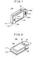
- Fig. 1 is a first perspective view showing a folded state (closed state) of a slide / rotation folding type portable communication terminal according to an embodiment of the invention and Fig. 2 is a second perspective view of the portable communication terminal as seen from a different viewpoint.
- the portable communication device 130 is provided with a lower case 111 as a first case and an upper case (upper lid) 112.
- the upper case 112 has a display portion 123 on its inner main surface, the display portion 123 being constituted by such a flat display device as LCD for example.
- the upper case 112 is connected, at its end portion, to the lower case 111 so as to be slidable and rotatable by a shaft substantially perpendicular to a display screen of the display portion 123.
- the lower case 111 has, on its inner main surface, a main operating portion (invisible in Figs. 1 and 2) as a first operating portion that has various keys. Even in a folded and superimposed state of both cases. the display portion 123 of the upper housing 112 is exposed because the type of this folding is not a bivalve type but a slide / rotation type.
- a sub-operating portion On the same main surface of the upper case 112 where the display portion 123 is disposed, there are provided, as a sub-operating portion (a second operating portion), a jog dial 121 and operating buttons 122a, 122b.
- the jog dial is a rotary dial operation means that also serves as a pushbutton switch.
- an ear receiver 124 is disposed near the display portion 123 on the main surface.
- a shutter button 25 is disposed on an outer side face of the lower case 111, as an imaging button which instructs imaging.
- the shutter button 25 substantially assumes a position at which it is abutted against the back side of the tip of the right hand forefinger.
- a battery cover 340 is disposed on an outer main surface of the lower case 111, and sideways of the battery cover 340 there are disposed a lens 31, a mirror 32 and a speaker 33 in the imaging portion.
- the mirror 32 is to serve as an alternative to a finder when the user performs imaging while orienting the lens 31 toward him- or herself.
- a positional relation and sizes of the lens 31, mirror 32 and speaker 33 are not limited to those illustrated in the figure.
- the portable communication terminal 130 In the closed state of the cases, as shown in Figs. 1 and 2, the display portion 123 is utilized as the finder screen and the shutter button 25 and the lens 31 are arranged in such a relation as illustrated in the figures, the portable communication terminal 130 has substantially the same form as the form of an existing digital camera and the user can perform imaging in the same way of handling as in the existing digital camera.
- Fig. 3 shows an appearance in a state in which the upper case 112 is being slid and rotated in its opening direction relative to the lower case 111 from the closed state of the portable communication terminal 130 illustrated in Figs. 1 and 2.
- the upper case 112 is rotated in the clockwise direction, it can be rotated in both clockwise and counterclockwise directions.
- Fig. 4 shows a state in which the upper case 112 has been fully opened via the state of Fig. 3.
- By rotating the upper case in the direction opposite to its opening direction it is possible to make a return to the folded state.
- a cable (not shown) for electric connection between the upper and lower cases extends through the connection of both cases and should be prevented from being twisted. Unless there arises such a problem as twisting of the cable, the upper case can be rotated in the same direction as its opening direction from the state illustrated in Fig. 4.
- a main operating portion 116 consisting of various keys, as well as a microphone 114, are disposed on the inner main surface of the lower case 111.
- Plural lugs 118 are formed at peripheral positions of the inner main surface of the lower case 111, serving as spacers for preventing the upper case 112 from depressing the keys of the main operating portion 116 erroneously when superimposed on the lower case.
- the lugs 118 are not essential to the invention. There may be adopted any other structure capable of preventing an erroneous depression of the keys of the main operating portion 116.
- the open state of the upper case 112 shown in Fig. 4 is a utilization mode mainly for utilizing the main operating portion 116 such as voice call, preparation and transmission of an electronic mail and editing of an address book and a memo book.
- the slide / rotation folding type portable communication terminal 130 is advantageous in that its size in a folded state can be reduced.
- the slide / rotation folding type is different from the bivalve folding type in the point that the display portion 123 is exposed even when both upper and lower cases are superimposed one on the other.
- the folded state of the portable communication terminal it is possible to check the contents of a received electronic mail and thus the utility of the display portion 123 is improved.
- Fig. 5 shows an appearance of a portable communication terminal 131 according to a modification of the above embodiment, in which the position of the shutter button 25 in the portable communication terminal 130 of Fig. 1 is changed from the lower case 111 to the upper case 112.
- An internal construction of the portable communication terminal 131 is the same as that of the portable communication terminal 130. There is no difference in operation between the two insofar as the imaging function is utilized in a closed state of the cases.
- the shutter button 25 be provided on the lower case 111. Also from the standpoint of the length of wiring of such an electric switch as the shutter button 25, it can be said preferable that the shutter button 25 be positioned on the lower case 111 side in which a battery is accommodated.
- Fig. 6 shows a hardware configuration of the portable communication terminal 130 of the above embodiment.
- a CPU 220 controls the entire operation of the portable communication terminal 130.
- the CPU 220 is connected through a control line 200 to a communication circuit 203, a display control unit 209, an operating unit 206, a ROM 207, a RAM 208, a folding detecting unit 218, an imaging unit 219, an imaging button 231 (corresponding to 25 in Fig. 1), and a voice processing unit 215, and controls these components.
- the communication circuit 203 takes charge of transmission and reception of information in the portable communication terminal and is connected by an antenna 202 to a base station through a radio interface.
- the display control unit 209 controls display in the display portion 210 (corresponding the display portion 123 in Fig. 1).
- the operating unit 206 (corresponding to the main operating portion 116 in Fig.1 ) receives an input instruction from the user.
- the ROM 207 is a memory for storing fixed programs executed by the CPU 220 and associated fixed data (e.g., font data).
- the RAM 208 provides a temporary storage area of data to be used for operation of the CPU 220 and also provides a work area.
- the folding detecting unit 218 is known means for detecting whether the upper case is open or closed relative to the lower case.
- the imaging unit 219 performs an imaging process and is provided with, in addition to the lens 31 referred to above, an imaging element such as CCD and a control circuit for controlling the imaging element.
- the voice processing unit 215 is connected to a microphone 232 (corresponding to 114 in Fig. 1), an ear receiver 233 (corresponding to 124 in Fig. 1) and a speaker 234 (corresponding to 33 in Fig. 2) and takes charge of voice input and output.
- a data line 201 is connected to the CPU 220, communication circuit 203, display control unit 209, ROM 207, RAM 208, voice processing unit 215 and imaging unit 219 and provides data transfer paths among them.
- a chargeable battery 45 is loaded into the lower case 111 in a replaceable manner and there is provided a power supply circuit 213 that is connected to the battery 45 to supply each of the components of the device with a predetermined electric power.
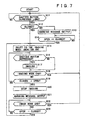
- Fig. 7 is a flowchart showing a first operation example related to imaging performed in the portable communication terminal of the embodiment.
- the illustrated processing is implemented by the execution with the CPU 220 of a computer program stored in the ROM 207.
- a predetermined operation of the shutter button 25 e.g., a continuous depression of the button for a predetermined time or longer, i.e., a long depression.
- a predetermined operation of the shutter button 25 e.g., a continuous depression of the button for a predetermined time or longer, i.e., a long depression.
- the shutter button 25 is exposed in the folded state (closed state) of the cases and further because in the non-imaging mode there can be no erroneous imaging even by depression of the shutter button 25.
- the second operating portion, including the jog dial is also exposed in the folded state (closed state) of the cases, a menu operation can be done with the jog dial, or it is possible to utilize the operation of either the operating button 122a or 122b.
- the use of the shutter button 25 is considered suitable for the shift-to-imaging mode instruction.
- the CPU checks whether the cases are in a closed state or not (S12), and if the answer is affirmative, a shift is made to the imaging mode (S15). At this time, the display portion 123 is begun to be used as a finder for imaging. As a result, an image of an object obtained through the lens is displayed on the display screen of the display portion 123 approximately on a real time basis. On the other hand, if the cases are not closed (i.e., if they are open), a warning message calling for closing of the upper case is outputted and displayed on the display screen (S13).
- a predetermined warning sound or voice message may be uttered from the speaker and/or the ear receiver. After output of the warning message and upon closing of the upper case (S14), a shift is made to the imaging mode starts (S15).
- step S17 When the shutter button is depressed after the shift to the imaging mode (S16), an imaging operation is executed (S17). If an instruction for end of the imaging mode is given (S18, No), the flow returns to the first step S11. The user gives the instruction for end of the imaging mode, more particularly, by operating for example the jog dial in the second operating portion. If the upper case is opened before issuance of the imaging mode end instruction (S19, Yes), the imaging is stopped (S20). Stopping the imaging means at least nullifying the depression of the shutter button. In addition, the monitoring function as a finder of the display portion may be turned OFF. Thereafter, the same warning message as in step S13 is outputted (S21).
- step S21 If an instruction for end of the imaging mode is given after step S21, the flow returns to the first step S11.
- This imaging mode end instruction is given by depressing a key (e.g., the clearing key) disposed in the main operating portion. Instead, operation of the second operating portion may be utilized.
- the flow returns to step S15, i.e., the imaging mode.
- Fig. 8 is a flowchart showing a second operation example related to imaging performed in the portable communication terminal of the embodiment.
- This operation example is similar to the first operation example shown in Fig. 7.
- Steps S31 to S39 in this second operation example are the same as steps S11 to S19 in Fig. 7.
- a difference resides in that the steps S20 to S23 in the first operation example are omitted in this second operation example. More specifically, in this second operation example, when the cases are opened after a shift to the imaging mode, the imaging mode is terminated. Therefore, for return to the imaging mode in this second operation example, it is necessary to close the cases and again depress the shutter button long.
- the first operation example is advantageous in that, after opening the cases to release the imaging mode, an immediate return to the imaging mode can be done by merely closing the cases.
- the second operation example is advantageous in that, when the imaging mode is to be released, this purpose can be achieved by merely opening the cases without operation of the first or the second operating portion.
Landscapes
- Engineering & Computer Science (AREA)
- Signal Processing (AREA)
- Multimedia (AREA)
- Computer Networks & Wireless Communication (AREA)
- Studio Devices (AREA)
- Telephone Set Structure (AREA)
- Indication In Cameras, And Counting Of Exposures (AREA)
- Camera Bodies And Camera Details Or Accessories (AREA)
- Structure And Mechanism Of Cameras (AREA)
Applications Claiming Priority (2)
| Application Number | Priority Date | Filing Date | Title |
|---|---|---|---|
| JP2003103319A JP4010975B2 (ja) | 2003-04-07 | 2003-04-07 | 携帯通信端末装置 |
| JP2003103319 | 2003-04-07 |
Publications (1)
| Publication Number | Publication Date |
|---|---|
| EP1467537A1 true EP1467537A1 (en) | 2004-10-13 |
Family
ID=32866711
Family Applications (1)
| Application Number | Title | Priority Date | Filing Date |
|---|---|---|---|
| EP04007974A Withdrawn EP1467537A1 (en) | 2003-04-07 | 2004-04-01 | Portable communication terminal device |
Country Status (5)
| Country | Link |
|---|---|
| US (1) | US7502636B2 (https=) |
| EP (1) | EP1467537A1 (https=) |
| JP (1) | JP4010975B2 (https=) |
| KR (1) | KR101053167B1 (https=) |
| CN (1) | CN100463463C (https=) |
Cited By (5)
| Publication number | Priority date | Publication date | Assignee | Title |
|---|---|---|---|---|
| EP1521430A1 (en) * | 2003-09-23 | 2005-04-06 | Samsung Electronics Co., Ltd. | Portable swing-type digital communication device with step compensating mechanism |
| EP1732299A1 (en) * | 2005-06-07 | 2006-12-13 | Samsung Electronics Co.,Ltd. | Method for changing the operation mode in a mobile terminal and mobile terminal for implementing the same |
| KR100681373B1 (ko) | 2004-11-15 | 2007-02-15 | 이근주 | 휴대용단말기의 회동개폐장치 |
| WO2006114667A3 (en) * | 2005-04-25 | 2007-05-10 | Nokia Corp | Improved mobile communication terminal |
| CN101877733A (zh) * | 2009-04-30 | 2010-11-03 | Lg电子株式会社 | 移动终端 |
Families Citing this family (33)
| Publication number | Priority date | Publication date | Assignee | Title |
|---|---|---|---|---|
| US8155718B2 (en) * | 2003-09-03 | 2012-04-10 | Samsung Electronics Co., Ltd. | Sliding/hinge apparatus for sliding/rotating type mobile terminals |
| USD542285S1 (en) * | 2003-09-11 | 2007-05-08 | Microsoft Corporation | Actuator for a portable electronic device |
| USD516565S1 (en) * | 2003-09-11 | 2006-03-07 | Microsoft Corporation | Actuator for a portable electronic device |
| USD539773S1 (en) * | 2003-12-11 | 2007-04-03 | Samsung Electronics Co. | Portable telephone |
| JP4552699B2 (ja) * | 2004-04-05 | 2010-09-29 | カシオ計算機株式会社 | 動画撮影装置、動画撮影制御方法、及び、動画撮影制御プログラム |
| JP4120942B2 (ja) * | 2004-07-22 | 2008-07-16 | ソニー株式会社 | 撮像装置 |
| KR100672513B1 (ko) * | 2004-11-19 | 2007-01-24 | 엘지전자 주식회사 | 바 타입 이동 통신 단말기 및 이의 작동 방법 |
| US7832055B2 (en) * | 2004-12-30 | 2010-11-16 | Sony Ericsson Mobile Communications Ab | Hinge |
| USD531974S1 (en) * | 2005-01-26 | 2006-11-14 | Samsung Electronics Co., Ltd. | Portable phone |
| USD531975S1 (en) * | 2005-01-26 | 2006-11-14 | Samsung Electronics Co., Ltd. | Portable phone |
| USD531973S1 (en) * | 2005-01-26 | 2006-11-14 | Samsung Electronics Co., Ltd. | Portable phone |
| KR100735289B1 (ko) * | 2005-06-07 | 2007-07-03 | 삼성전자주식회사 | 휴대단말기의 통화수행 방법 |
| USD545802S1 (en) * | 2005-09-08 | 2007-07-03 | Samsung Electronics Co., Ltd. | Portable phone |
| KR100784542B1 (ko) * | 2005-10-20 | 2007-12-11 | 엘지전자 주식회사 | 면접촉 축회전 이동통신단말기 |
| KR20070073273A (ko) * | 2006-01-04 | 2007-07-10 | 삼성전자주식회사 | 휴대용 단말기에서 폴더의 회전 상태를 감지하는 장치 및방법 |
| US7860538B2 (en) * | 2006-02-28 | 2010-12-28 | Lg Electronics Inc. | Mobile terminal |
| US7996050B2 (en) * | 2006-02-28 | 2011-08-09 | Lg Electronics Inc. | Input device for an electronic device and electronic device having the same |
| US8243021B2 (en) * | 2006-03-31 | 2012-08-14 | Intel Corporation | Slide and rotate display configurations for a handheld computing device |
| KR101102811B1 (ko) * | 2006-06-05 | 2012-01-05 | 엘지전자 주식회사 | 이동 통신 단말기의 회신 처리 방법 및 그 이동 통신단말기 |
| KR100797417B1 (ko) * | 2006-07-11 | 2008-01-23 | 삼성전자주식회사 | 커스텀 화이트밸런스 조정장치 및 방법 |
| JP4757754B2 (ja) * | 2006-09-22 | 2011-08-24 | 富士通株式会社 | 電子機器、その表示制御方法、その表示制御プログラム及び記録媒体 |
| KR101122092B1 (ko) * | 2006-11-28 | 2012-06-14 | 엘지전자 주식회사 | 롤-키(roll-key)를 구비한 이동통신 단말기 및 이를이용한 입력신호 처리 방법 |
| KR100836139B1 (ko) * | 2006-12-28 | 2008-06-09 | 삼성전자주식회사 | 스위블 바디의 회전 방향 감지 장치를 갖는 스위블 타입휴대용 단말기 및 그것을 이용한 스위블 바디의 회전 방향감지 방법 |
| AU318956S (en) * | 2007-06-20 | 2008-04-21 | Microsoft Mobile Oy | Handset |
| JP4175429B1 (ja) * | 2007-09-04 | 2008-11-05 | 松下電器産業株式会社 | 折り畳み式携帯端末装置および、折り畳み式携帯電話機 |
| USD596630S1 (en) | 2007-10-29 | 2009-07-21 | Sony Ericsson Mobile Communications Japan, Inc. | Mobile phone |
| JP2010278941A (ja) * | 2009-06-01 | 2010-12-09 | Panasonic Corp | 通信システム |
| TWD136573S1 (zh) * | 2009-07-23 | 2010-08-21 | 宏達國際電子股份有限公司 | 行動電話 |
| TW201104330A (en) * | 2009-07-24 | 2011-02-01 | Asia Optical Co Inc | Photography apparatus capable of simultaneously protecting the lens set and the display |
| US8672427B2 (en) * | 2010-01-25 | 2014-03-18 | Pepsico, Inc. | Video display for product merchandisers |
| JP5700204B2 (ja) * | 2011-01-26 | 2015-04-15 | カシオ計算機株式会社 | 頭部装着型撮像装置 |
| USD676013S1 (en) * | 2012-04-27 | 2013-02-12 | Fih (Hong Kong) Limited | Mobile phone |
| CN103533223A (zh) * | 2013-10-21 | 2014-01-22 | 明基电通有限公司 | 可携式电子装置 |
Citations (3)
| Publication number | Priority date | Publication date | Assignee | Title |
|---|---|---|---|---|
| WO2001084729A1 (en) * | 2000-04-28 | 2001-11-08 | Motorola Inc. | Portable electronic device with an adaptable user interface |
| EP1298890A2 (en) * | 2001-09-28 | 2003-04-02 | Nec Corporation | Foldable portable information terminal |
| EP1379056A2 (en) * | 2002-06-21 | 2004-01-07 | Sharp Kabushiki Kaisha | Foldable cellular telephone incorporating two separate displays and a camera |
Family Cites Families (23)
| Publication number | Priority date | Publication date | Assignee | Title |
|---|---|---|---|---|
| JPS6480145A (en) * | 1987-09-22 | 1989-03-27 | Matsushita Electric Industrial Co Ltd | Portable telephone set |
| US6009336A (en) * | 1996-07-10 | 1999-12-28 | Motorola, Inc. | Hand-held radiotelephone having a detachable display |
| JP3459744B2 (ja) * | 1997-03-11 | 2003-10-27 | シャープ株式会社 | 携帯型テレビ電話装置 |
| JP4199837B2 (ja) * | 1997-05-29 | 2008-12-24 | カシオ計算機株式会社 | 複合機器 |
| JP3516328B2 (ja) * | 1997-08-22 | 2004-04-05 | 株式会社日立製作所 | 情報通信端末装置 |
| JP2002135380A (ja) * | 2000-10-27 | 2002-05-10 | Matsushita Electric Ind Co Ltd | 折り畳み式携帯型電子機器 |
| JP2002171189A (ja) * | 2000-11-30 | 2002-06-14 | Matsushita Electric Ind Co Ltd | 携帯端末 |
| JP3929696B2 (ja) * | 2000-12-05 | 2007-06-13 | 富士フイルム株式会社 | カメラ |
| JP3778807B2 (ja) * | 2001-03-30 | 2006-05-24 | 三洋電機株式会社 | 折畳式通信端末装置および画像表示方法 |
| US7173665B2 (en) * | 2001-03-30 | 2007-02-06 | Sanyo Electric Co., Ltd. | Folding mobile communication terminal |
| JP3574084B2 (ja) * | 2001-04-03 | 2004-10-06 | 三洋電機株式会社 | 折畳式通信端末装置および撮影制御方法 |
| JP3787760B2 (ja) * | 2001-07-31 | 2006-06-21 | 松下電器産業株式会社 | カメラ付き携帯電話装置 |
| JP2003069869A (ja) * | 2001-08-27 | 2003-03-07 | Olympus Optical Co Ltd | カメラ機能を有する携帯型情報端末機器 |
| JP3901011B2 (ja) * | 2002-05-20 | 2007-04-04 | ソニー・エリクソン・モバイルコミュニケーションズ株式会社 | 携帯電話機およびストロボモジュール |
| JP3872390B2 (ja) * | 2002-07-24 | 2007-01-24 | 京セラ株式会社 | 携帯端末装置 |
| JP3675430B2 (ja) * | 2002-09-20 | 2005-07-27 | 株式会社日立製作所 | 携帯電話機 |
| JP2004112559A (ja) * | 2002-09-20 | 2004-04-08 | Hitachi Ltd | 携帯電話 |
| JP4402355B2 (ja) * | 2003-01-21 | 2010-01-20 | 京セラ株式会社 | 重ね型携帯端末装置 |
| WO2004066616A1 (ja) * | 2003-01-21 | 2004-08-05 | Matsushita Electric Industrial Co., Ltd. | カメラ付き携帯装置 |
| JP4019189B2 (ja) * | 2003-02-04 | 2007-12-12 | ソニー・エリクソン・モバイルコミュニケーションズ株式会社 | 携帯無線機 |
| JP2004247218A (ja) * | 2003-02-14 | 2004-09-02 | Canon Inc | 電子機器 |
| JP3869813B2 (ja) * | 2003-03-04 | 2007-01-17 | 三洋電機株式会社 | 電子撮像装置 |
| JP3869812B2 (ja) * | 2003-03-04 | 2007-01-17 | 三洋電機株式会社 | 電子撮像装置 |
-
2003
- 2003-04-07 JP JP2003103319A patent/JP4010975B2/ja not_active Expired - Fee Related
-
2004
- 2004-04-01 EP EP04007974A patent/EP1467537A1/en not_active Withdrawn
- 2004-04-06 US US10/817,818 patent/US7502636B2/en not_active Expired - Fee Related
- 2004-04-07 CN CNB2004100325122A patent/CN100463463C/zh not_active Expired - Fee Related
- 2004-04-07 KR KR1020040023725A patent/KR101053167B1/ko not_active Expired - Fee Related
Patent Citations (3)
| Publication number | Priority date | Publication date | Assignee | Title |
|---|---|---|---|---|
| WO2001084729A1 (en) * | 2000-04-28 | 2001-11-08 | Motorola Inc. | Portable electronic device with an adaptable user interface |
| EP1298890A2 (en) * | 2001-09-28 | 2003-04-02 | Nec Corporation | Foldable portable information terminal |
| EP1379056A2 (en) * | 2002-06-21 | 2004-01-07 | Sharp Kabushiki Kaisha | Foldable cellular telephone incorporating two separate displays and a camera |
Cited By (7)
| Publication number | Priority date | Publication date | Assignee | Title |
|---|---|---|---|---|
| EP1521430A1 (en) * | 2003-09-23 | 2005-04-06 | Samsung Electronics Co., Ltd. | Portable swing-type digital communication device with step compensating mechanism |
| US7158371B2 (en) | 2003-09-23 | 2007-01-02 | Samsung Electronics Co., Ltd. | Portable swing-type digital communication device with step compensating mechanism |
| KR100681373B1 (ko) | 2004-11-15 | 2007-02-15 | 이근주 | 휴대용단말기의 회동개폐장치 |
| WO2006114667A3 (en) * | 2005-04-25 | 2007-05-10 | Nokia Corp | Improved mobile communication terminal |
| EP1732299A1 (en) * | 2005-06-07 | 2006-12-13 | Samsung Electronics Co.,Ltd. | Method for changing the operation mode in a mobile terminal and mobile terminal for implementing the same |
| CN101877733A (zh) * | 2009-04-30 | 2010-11-03 | Lg电子株式会社 | 移动终端 |
| CN101877733B (zh) * | 2009-04-30 | 2014-07-16 | Lg电子株式会社 | 移动终端 |
Also Published As
| Publication number | Publication date |
|---|---|
| US20040198460A1 (en) | 2004-10-07 |
| US7502636B2 (en) | 2009-03-10 |
| CN100463463C (zh) | 2009-02-18 |
| JP2004312389A (ja) | 2004-11-04 |
| KR20040087913A (ko) | 2004-10-15 |
| CN1571430A (zh) | 2005-01-26 |
| KR101053167B1 (ko) | 2011-08-02 |
| JP4010975B2 (ja) | 2007-11-21 |
Similar Documents
| Publication | Publication Date | Title |
|---|---|---|
| US7502636B2 (en) | Portable communication terminal device for communication and image data | |
| KR100575999B1 (ko) | 바 타입 휴대용 무선 단말기 | |
| US8441227B2 (en) | Portable terminal | |
| KR100304484B1 (ko) | 정보통신단말장치 | |
| EP1762083B1 (en) | Communication device including one or more electrical control buttons in an upper housing part | |
| KR100665420B1 (ko) | 휴대용 무선 전화기 | |
| US7926958B2 (en) | Mobile terminal having projector and method for controlling the same | |
| US6865400B2 (en) | User interfacing device for PDA/wireless terminal | |
| US20060135225A1 (en) | Handheld electronic data processing device | |
| US20040235540A1 (en) | Portable terminal unit | |
| KR20030046891A (ko) | 상폴더 외부에 터치스크린과 기능키를 구비하는 폴더형이동통신단말기 | |
| KR20040079134A (ko) | 바 타입 휴대용 무선 단말기의 탁상용 충전기 | |
| JP2002135380A (ja) | 折り畳み式携帯型電子機器 | |
| EP1762084B1 (en) | Communication device including one or more electrical control buttons in an upper housing part | |
| US20050020239A1 (en) | Portable communication device and method of sensing camera operation mode in the portable communication device | |
| JP4715208B2 (ja) | 携帯電話機 | |
| US7606605B2 (en) | Two-way folder-type terminal | |
| US7342806B2 (en) | Portable electronic device with multiple input interfaces | |
| JP2005323049A (ja) | 撮像装置 | |
| JP2004128780A (ja) | キーロック機能付き携帯電話機 | |
| US8326367B2 (en) | Foldable image processing apparatus | |
| JP3942808B2 (ja) | 携帯情報端末機 | |
| US7590431B2 (en) | System and method for outputting dual voice of mobile terminal | |
| JP2002171320A (ja) | 移動体通信端末 | |
| JP2001358811A (ja) | 携帯型情報端末装置 |
Legal Events
| Date | Code | Title | Description |
|---|---|---|---|
| PUAI | Public reference made under article 153(3) epc to a published international application that has entered the european phase |
Free format text: ORIGINAL CODE: 0009012 |
|
| AK | Designated contracting states |
Kind code of ref document: A1 Designated state(s): AT BE BG CH CY CZ DE DK EE ES FI FR GB GR HU IE IT LI LU MC NL PL PT RO SE SI SK TR |
|
| AX | Request for extension of the european patent |
Extension state: AL HR LT LV MK |
|
| 17P | Request for examination filed |
Effective date: 20050218 |
|
| AKX | Designation fees paid |
Designated state(s): DE FR GB |
|
| RAP1 | Party data changed (applicant data changed or rights of an application transferred) |
Owner name: SONY MOBILE COMMUNICATIONS JAPAN, INC. |
|
| 17Q | First examination report despatched |
Effective date: 20160907 |
|
| STAA | Information on the status of an ep patent application or granted ep patent |
Free format text: STATUS: EXAMINATION IS IN PROGRESS |
|
| STAA | Information on the status of an ep patent application or granted ep patent |
Free format text: STATUS: THE APPLICATION IS DEEMED TO BE WITHDRAWN |
|
| 18D | Application deemed to be withdrawn |
Effective date: 20170118 |