EP1467444A2 - Steckdoseneinsatz einer Steckdose mit in einer Berührungsschutzvorrichtung geführtem Schieber - Google Patents
Steckdoseneinsatz einer Steckdose mit in einer Berührungsschutzvorrichtung geführtem Schieber Download PDFInfo
- Publication number
- EP1467444A2 EP1467444A2 EP04006630A EP04006630A EP1467444A2 EP 1467444 A2 EP1467444 A2 EP 1467444A2 EP 04006630 A EP04006630 A EP 04006630A EP 04006630 A EP04006630 A EP 04006630A EP 1467444 A2 EP1467444 A2 EP 1467444A2
- Authority
- EP
- European Patent Office
- Prior art keywords
- slide
- base plate
- socket insert
- housing
- plug
- Prior art date
- Legal status (The legal status is an assumption and is not a legal conclusion. Google has not performed a legal analysis and makes no representation as to the accuracy of the status listed.)
- Withdrawn
Links
- 230000037431 insertion Effects 0.000 claims description 6
- 238000003780 insertion Methods 0.000 claims description 6
- 230000001681 protective effect Effects 0.000 description 3
- 238000002347 injection Methods 0.000 description 2
- 239000007924 injection Substances 0.000 description 2
- 238000009434 installation Methods 0.000 description 2
- 238000005452 bending Methods 0.000 description 1
- 230000000903 blocking effect Effects 0.000 description 1
- 230000006378 damage Effects 0.000 description 1
- 238000009418 renovation Methods 0.000 description 1
Images

Classifications
-
- H—ELECTRICITY
- H01—ELECTRIC ELEMENTS
- H01R—ELECTRICALLY-CONDUCTIVE CONNECTIONS; STRUCTURAL ASSOCIATIONS OF A PLURALITY OF MUTUALLY-INSULATED ELECTRICAL CONNECTING ELEMENTS; COUPLING DEVICES; CURRENT COLLECTORS
- H01R13/00—Details of coupling devices of the kinds covered by groups H01R12/70 or H01R24/00 - H01R33/00
- H01R13/44—Means for preventing access to live contacts
- H01R13/447—Shutter or cover plate
- H01R13/453—Shutter or cover plate opened by engagement of counterpart
- H01R13/4534—Laterally sliding shutter
Definitions
- the invention relates to a socket insert of a socket with in a Touch protection device guided slide according to the preamble of the claim 1.
- the invention can, for example, with flush-mounted and surface-mounted sockets be used.
- DE 24 02 569 B2 describes an electrical socket with a locking device to protect against unipolar insertion of a plug or single pin using a spring-loaded, tiltable and perpendicular to the connecting line of the socket insertion holes movable one-piece slide known with inclined surfaces has provided projections, one of which is in the locked position in engages a socket through hole. In addition, engage in the locking position Locking cams in wedge-shaped recesses in the holding plate (base plate) of the socket insert one, with the slider tipping over several tilting projections.
- DE 198 49 883 A1 discloses an electrical socket with socket base, on the front, releasable cover and a child lock known in which the child lock attached to the socket base and with a held on the socket base, the bottom of the cover adjacent cover plate is covered. So that's it Childproof lock even when the cover is removed, e.g. for installation or renovation work, effective.
- the blocking piece can be a rotary slide valve or linear slide valve.
- DE 102 03 894 C1 describes a protective contact socket on the socket base attached touch protection device proposed, which consists of a housing with longitudinal slide guided in it and spring-loaded by a return spring exists, which plug openings made in the housing for insertion of connector pins of a connector by means of locking bevels closes and these plug openings only with simultaneous intervention both connector pins opens.
- the longitudinal slide is wedge-shaped and has one Release bevels so that the release bevels required to open the longitudinal slide by adding the release bevels of a locking cam and the Release slope of the longitudinal slide results.
- the longitudinal slide has at least one Tilting edge over which he only one plug opening in the event of one-sided loading tilts that three locking cams of the longitudinal slide into the unloaded Plug opening, in a locking recess in the housing cover and in a locking recess engage in the lower part of the housing and lock there.
- the invention has for its object a socket insert of a socket with a slide in an extremely robust contact protection device specified type.
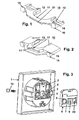
- the slide 10 is preferably a plastic injection molded part from a main body 11 with a central Opening and two side arms 12 formed, the side arms 12 on their tops, d. H. on their main surfaces facing the plug openings of the socket insert, as inclined planes inclined surfaces (engagement troughs) 13 for the Engagement of connector pins of a connector and stepped on the edge of these inclined surfaces 13 Have edges 14.
- the tops of both side arms 12 also have Projections 15, while the undersides of the side arms 12 are provided with projections 16 are.
- the main body is on its end face facing away from the central opening 11 with a groove 21 for engagement and for sliding guidance of a leg Provide return spring (leg spring).
- FIG. 2 shows a view of the underside of a slide.
- Several tipping edges (Cam) 17 on the main body 11 and on the side arms 12 enable one Tilting movement of the slide 10, preferably designed as a longitudinal slide, such as will be explained in more detail below.
- the projections 16 and 15 are clear can be seen on the underside or the top of the side arms 12.
- Fig. 4 is a section through a with the slide 10 and the return spring 18-here Leg spring - equipped housing 6 of the contact protection device shown.
- the main body of the leg spring is fixed by means of a pin of the housing 6, while the first leg of the leg spring has a projection on the edge of the housing is fixed and the second leg of the leg spring during longitudinal movement of the slide 10 slides in the groove 21 of the main body 11.
- Position is the slider 10 in the tilt position, d. H. in the locked position, one of the two projections 16 on the underside of one side arm 12 in the corresponding recess 9 engages in the base plate 7 of the housing 6.
- the projection 15 engages on the upper side of the other side arm 12 a corresponding recess 5 in the base plate 2 of the socket insert 1 (not shown).
- the slide (longitudinal slide) is 10 between a closed position (rest position) and an open one Position (with plug inserted) is longitudinally movable.
- the closed position the side arms 12 of the slide 10 completely cover the plug openings 3.
- the slide 10 against the spring force of the return spring (leg spring) 18 in its open position pressed (linear movement).
- the connector pins slide initially along the inclined surfaces 13 of the side arms 12 and then engage through the plug openings 20 of the base plate 7 of the housing 6 into the plug contacts of the socket base.
- a longitudinal movement of the slide 10 is thus independent of one another through these three effective locking devices 14/3, 15/5, 16/9 effectively prevented and the plug openings 3 and 20 remain closed.
- 5 and 6 are two Cuts through a socket insert 1 in the locked above Position shown.
- the socket insert 1 has one for mounting the contact protection device central hollow pin in the base plate 6, which the aforementioned central bore 4th has, in this central bore 4, a locking lug protrudes with an inclined surface.
- the housing 6 of the contact protection device has a central hollow pin in the base plate 7, which has the mentioned central bore 8 and one on its outer surface projecting locking lug with inclined surface. During installation of the housing 6 on the socket insert 1, these two latches latch together.
- the one inserted into both central bores 4, 8 for mounting the socket base on the socket insert 1, the central fastening screw 19 blocks it Latching.
- the return spring as a helical spring, for example train.
- the proposed one Configuration not only with single sockets, but also with double sockets use.
- the proposals according to the invention are suitable both for surface mounting and also for concealed versions.
Landscapes
- Connector Housings Or Holding Contact Members (AREA)
- Details Of Connecting Devices For Male And Female Coupling (AREA)
Abstract
Description
- Fig.1
- eine Sicht auf die Oberseite eines Schiebers,
- Fig. 2
- eine Sicht auf die Unterseite eines Schiebers,
- Fig. 3
- eine prinzipielle Darstellung der Komponenten des Steckdoseneinsatzes,
- Fig. 4
- einen Schnitt durch ein mit dem Schieber bestücktes Gehäuse der Berührungsschutzvorrichtung,
- Fig. 5, 6
- zwei Schnitte durch einen Steckdoseneinsatz in verriegelter Position.
- Der eigentliche Steckdoseneinsatz 1 mit Bodenplatte 2, zwei Steckeröffnungen 3, zentraler Bohrung 4 und Aussparungen 5 in der Bodenplatte 2 zum bedarfsweisen Eingriff eines Vorsprunges 15 des Schiebers 10.
- Das komplett mit Schieber und Rückstellfeder bestückte, vorzugsweise als Kunststoff-Spritzgießteil gefertigte Gehäuse 6 der Berührungsschutzvorrichtung mit Bodenplatte 7, zentraler Bohrung 8 in der Bodenplatte, Aussparungen 9 in der Bodenplatte 7 zum bedarfsweisen Eingriff eines Vorsprungs 16 des Schiebers 10 und zwei Steckeröffnungen 20.
- Eine Befestigungsschraube 19 zur Durchführung durch die Bohrungen 4 und 8 zwecks Montage eines Steckdosensockels.
- die abgesetzte Kante 14 des nicht belasteten Seitenarms 12 des Schiebers 10 in die nicht mit dem Stift beaufschlagte Steckeröffnung 3 des Steckdoseneinsatzes 1 eingreift und dort verrastet (siehe Fig. 6),
- der Vorsprung 15 des nicht belasteten Seitenarms 12 des Schiebers 10 in die entsprechende Aussparung 5 in der Bodenplatte 2 des Steckdoseneinsatzes 1 eingreift und dort verrastet (siehe Fig. 5) und
- der Vorsprung 16 des belasteten Seitenarms 12 in die entsprechenden Aussparung 9 in der Bodenplatte 7 des Gehäuses 6 eingreift und dort verrastet (siehe Fig. 5).
- 1
- Steckdoseneinsatz
- 2
- Bodenplatte
- 3
- Steckeröffnungen
- 4
- zentrale Bohrung in Bodenplatte 2
- 5
- Aussparung in Bodenplatte 2 zum Eingriff eines Vorsprungs 15
- 6
- Gehäuse der Berührungsschutzvorrichtung
- 7
- Bodenplatte
- 8
- zentrale Bohrung in Bodenplatte 7
- 9
- Aussparung in Bodenplatte 7 zum Eingriff eines Vorsprungs 16
- 10
- Schieber
- 11
- Hauptkörper
- 12
- Seitenarme
- 13
- Schrägflächen auf der Oberseite der Seitenarme des Schiebers (für Steckerstifte)
- 14
- abgesetzte Kante am Rande einer Schrägfläche 13 zum Eingriff in Steckeröffnungen 3
- 15
- Vorsprung auf der Oberseite der Seitenarme 12 des Schiebers 10 zum Eingriff in eine Aussparung 5 in der Bodenplatte 2 des Steckdoseneinsatzes 1
- 16
- Vorsprung auf der Unterseite der Seitenarme 12 des Schiebers 10 zum Eingriff in eine Aussparung 9 in der Bodenplatte 7 des Gehäuses 6
- 17
- Kippkante
- 18
- Rückstellfeder (hier Schenkelfeder)
- 19
- zentrale Befestigungsschraube
- 20
- Steckeröffnungen der Berührungsschutzvorrichtung
- 21
- Nut
Claims (2)
- Steckdoseneinsatz einer Steckdose mit in einem Gehäuse (6) einer Berührungsschutzvorrichtung geführtem, von einer Rückstellfeder (18) beaufschlagtem Schieber (10), dessen Hauptkörper (11) zwei Seitenarme (12) zum Verschluss von in der Bodenplatte (2) des Steckdoseneinsatzes (1) eingebrachten Steckeröffnungen (3) zur Einführung von Steckerstiften eines Steckers aufweist, wobeidadurch gekennzeichnet, dassauf der Oberseite der Seitenarme (12) des Schiebers (10) Schrägflächen (13) für den Eingriff der Steckerstifte sowie abgesetzte Kanten (14) am Rande dieser Schrägflächen (13) vorgesehen sind,auf der Oberseite der Seitenarme (12) des Schiebers (10) Vorsprünge (15) vorgesehen sind, denen bei geschlossener Position des Berührungsschutzes Aussparungen (5) in der Bodenplatte (2) des Steckdoseneinsatzes (1) gegenüberliegen,der Schieber (10) mindestens eine Kippkante (17) aufweist, über die er bei einseitiger Belastung lediglich einer Steckeröffnung (3) derart kippt, dass die abgesetzte Kante (14) des nicht belasteten Seitenarms (12) in die nicht beaufschlagte Steckeröffnung (3) eingreift und dort verrastet, wobei der Vorsprung (15) des nicht belasteten Seitenarms (12) in die entsprechende Aussparung (5) in der Bodenplatte (2) des Steckdoseneinsatzes (1) eingreift und dort verrastet,die Steckeröffnungen (3) lediglich bei gleichzeitigem Eingriff beider Steckerstifte öffnen,auf der Unterseite der Seitenarme (12) des Schiebers (10) Vorsprünge (16) vorgesehen sind, denen bei geschlossener Position des Berührungsschutzes Aussparungen (9) in der Bodenplatte (7) des Gehäuses (6) der Berührungsschutzvorrichtung gegenüberliegen, wobei bei Kippen des Schiebers (10) aufgrund einer einseitigen Belastung der Vorsprung (16) des belasteten Seitenarms (12) in die entsprechende Aussparung (9) in der Bodenplatte (7) des Gehäuses (6) eingreift und dort verrastet unddass eine Schenkelfeder (18) als Rückstellfeder eingesetzt ist, wobei das Gehäuse (6) einen Zapfen zur Halterung des Hauptkörpers der Schenkelfeder, einen Vorsprung zur Halterung eines ersten Schenkels der Rückstellfeder und der Schieber (10) eine Nut (21) für den gleitenden Eingriff eines zweiten Schenkels der Rückstellfeder aufweisen.
- Steckdoseneinsatz nach Anspruch 1, dadurch gekennzeichnet, dass der Steckdoseneinsatz (1) einen zentralen Hohlzapfen in der Bodenplatte (2) besitzt, welcher eine zentrale Bohrung (4) aufweist, wobei in diese zentrale Bohrung (4) eine Rastnase mit Schrägfläche vorspringt, dass das Gehäuse (6) der Berührungsschutzvorrichtung einen zentralem Hohlzapfen in der Bodenplatte (7) besitzt, welcher eine zentrale Bohrung (8) sowie eine an seiner Außenmantelfläche vorspringende Rastnase mit Schrägfläche aufweist, dass diese beiden Rastnasen gegenseitig verrasten und dass eine in beide zentrale Bohrungen (4, 8) eingeführte zentrale Befestigungsschraube (19) diese Verrastung blockiert.
Applications Claiming Priority (2)
| Application Number | Priority Date | Filing Date | Title |
|---|---|---|---|
| DE2003115557 DE10315557B3 (de) | 2003-04-05 | 2003-04-05 | Steckdoseneinsatz einer Steckdose mit in einer Berührungsschutzvorrichtung geführtem Schieber |
| DE10315557 | 2003-04-05 |
Publications (2)
| Publication Number | Publication Date |
|---|---|
| EP1467444A2 true EP1467444A2 (de) | 2004-10-13 |
| EP1467444A3 EP1467444A3 (de) | 2007-05-30 |
Family
ID=32695243
Family Applications (1)
| Application Number | Title | Priority Date | Filing Date |
|---|---|---|---|
| EP04006630A Withdrawn EP1467444A3 (de) | 2003-04-05 | 2004-03-19 | Steckdoseneinsatz einer Steckdose mit in einer Berührungsschutzvorrichtung geführtem Schieber |
Country Status (3)
| Country | Link |
|---|---|
| EP (1) | EP1467444A3 (de) |
| DE (1) | DE10315557B3 (de) |
| NO (1) | NO20041388L (de) |
Families Citing this family (3)
| Publication number | Priority date | Publication date | Assignee | Title |
|---|---|---|---|---|
| DE102005011435B4 (de) * | 2005-03-12 | 2006-11-23 | Abb Patent Gmbh | Steckdoseneinsatz einer Steckdose mit erhöhtem Berührungsschutz |
| DE102009060379C5 (de) * | 2009-12-24 | 2013-12-12 | Albrecht Jung Gmbh & Co. Kg | Elektrische Steckvorrichtung |
| CN115411556B (zh) * | 2022-10-13 | 2025-03-04 | 江苏奥功电能科技有限公司 | 一种新型带保护门防触电欧标充电插座的使用方法 |
Family Cites Families (3)
| Publication number | Priority date | Publication date | Assignee | Title |
|---|---|---|---|---|
| EP0512208B1 (de) * | 1991-05-03 | 1996-01-10 | GIRA GIERSIEPEN GmbH. & CO. KG. | Elektrisches Installationsgerät, insbesondere Schutzkontaktsteckdose mit einer Kinderschutzeinrichtung |
| DE19849883B4 (de) * | 1998-10-29 | 2005-06-30 | Merten Gmbh & Co. Kg | Elektrische Steckdose mit einer Kindersicherung |
| DE10203894C1 (de) * | 2002-01-31 | 2003-04-30 | Abb Patent Gmbh | Schutzkontaktsteckdose mit am Steckdosensockel befestigter Berührungsschutzvorrichtung |
-
2003
- 2003-04-05 DE DE2003115557 patent/DE10315557B3/de not_active Expired - Fee Related
-
2004
- 2004-03-19 EP EP04006630A patent/EP1467444A3/de not_active Withdrawn
- 2004-04-02 NO NO20041388A patent/NO20041388L/no not_active Application Discontinuation
Also Published As
| Publication number | Publication date |
|---|---|
| DE10315557B3 (de) | 2004-08-12 |
| EP1467444A3 (de) | 2007-05-30 |
| NO20041388L (no) | 2004-10-06 |
Similar Documents
| Publication | Publication Date | Title |
|---|---|---|
| DE102004038123B4 (de) | Elektrischer Stecker und elektrische Steckeraufnahme | |
| DE202020105647U1 (de) | Sicherungslasttrennschalter, insbesondere NH-Sicherungslasttrennschalter | |
| DE10132560C2 (de) | Steckverbinder | |
| DE10202341C1 (de) | Berührungsschutzvorrichtung für eine Schutzkontakt-Steckdose mit federbelastetem Drehschieber | |
| DE102022103915B3 (de) | Sicherungslasttrennschalter | |
| DE10315557B3 (de) | Steckdoseneinsatz einer Steckdose mit in einer Berührungsschutzvorrichtung geführtem Schieber | |
| DE10216209C1 (de) | Berührungsschutzvorrichtung mit Längsschieber für eine elektrische Steckdose | |
| DE102020119864A1 (de) | Leiteranschlussklemme | |
| DE10203894C1 (de) | Schutzkontaktsteckdose mit am Steckdosensockel befestigter Berührungsschutzvorrichtung | |
| DE10248892B3 (de) | Stecker zum Verbinden mit einer Steckbuchse | |
| DE4005136C2 (de) | ||
| DE102020125730B3 (de) | Sicherungslasttrennschalter, insbesondere nh-sicherungslasttrennschalter | |
| DE3015138A1 (de) | Verriegelbarer steckverbinder | |
| DE10216208C1 (de) | Berührungsschutzvorrichtung für eine elektrische Steckdose | |
| DE102017215516A1 (de) | Elektrischer Steckverbinder mit Fingerentriegelungsschutz | |
| EP1298763B1 (de) | Berührungsschutzvorrichtung für eine Schutzkontakt-Steckdose | |
| DE10315556B3 (de) | Steckdoseneinsatz einer Steckdose mit in einer Berührungsschutzvorrichtung geführtem Längsschieber | |
| DE10206025C1 (de) | Berührungsschutzvorrichtung für eine Schutzkontakt-Steckdose mit Längsschieber | |
| DE10225562C1 (de) | Steckdoseneinsatz einer Steckdose mit in einer Berührungsschutzvorrichtung geführtem Längsschieber | |
| DE10202342C1 (de) | Berührungsschutzvorrichtung für eine Schutzkontakt-Steckdose unter Einsatz eines Längsschiebers mit direkt angespitzter Rückstellfeder | |
| DE2326286A1 (de) | Werkzeug | |
| DE10225563C1 (de) | Steckdoseneinsatz einer Steckdose mit in einer Berührungsschutzvorrichtung geführtem Drehschieber | |
| DE10225564C1 (de) | Steckdoseneinsatz einer Steckdose mit in einer Berührungsschutzvorrichtung geführtem Drehschieber | |
| EP1385236B1 (de) | Steckdoseneinsatz einer Steckdose mit in einer Berührungsschutzvorrichtung geführtem Längsschieber | |
| DE10216199C1 (de) | Steckdoseneinsatz einer Steckdose mit in einer Berührungsschutzvorrichtung geführtem Längsschieber |
Legal Events
| Date | Code | Title | Description |
|---|---|---|---|
| PUAI | Public reference made under article 153(3) epc to a published international application that has entered the european phase |
Free format text: ORIGINAL CODE: 0009012 |
|
| AK | Designated contracting states |
Kind code of ref document: A2 Designated state(s): AT BE BG CH CY CZ DE DK EE ES FI FR GB GR HU IE IT LI LU MC NL PL PT RO SE SI SK TR |
|
| AX | Request for extension of the european patent |
Extension state: AL LT LV MK |
|
| PUAL | Search report despatched |
Free format text: ORIGINAL CODE: 0009013 |
|
| AK | Designated contracting states |
Kind code of ref document: A3 Designated state(s): AT BE BG CH CY CZ DE DK EE ES FI FR GB GR HU IE IT LI LU MC NL PL PT RO SE SI SK TR |
|
| AX | Request for extension of the european patent |
Extension state: AL LT LV MK |
|
| RIC1 | Information provided on ipc code assigned before grant |
Ipc: H01R 13/453 20060101AFI20070420BHEP |
|
| AKX | Designation fees paid |
Designated state(s): AT DE ES FI NL SE |
|
| STAA | Information on the status of an ep patent application or granted ep patent |
Free format text: STATUS: THE APPLICATION IS DEEMED TO BE WITHDRAWN |
|
| 18D | Application deemed to be withdrawn |
Effective date: 20071002 |