EP1466848A2 - Bogenanleger zum Vereinzeln von Bogen - Google Patents
Bogenanleger zum Vereinzeln von Bogen Download PDFInfo
- Publication number
- EP1466848A2 EP1466848A2 EP04007420A EP04007420A EP1466848A2 EP 1466848 A2 EP1466848 A2 EP 1466848A2 EP 04007420 A EP04007420 A EP 04007420A EP 04007420 A EP04007420 A EP 04007420A EP 1466848 A2 EP1466848 A2 EP 1466848A2
- Authority
- EP
- European Patent Office
- Prior art keywords
- sheet
- separator
- sheet separator
- transport
- transport direction
- Prior art date
- Legal status (The legal status is an assumption and is not a legal conclusion. Google has not performed a legal analysis and makes no representation as to the accuracy of the status listed.)
- Granted
Links
Images



Classifications
-
- B—PERFORMING OPERATIONS; TRANSPORTING
- B65—CONVEYING; PACKING; STORING; HANDLING THIN OR FILAMENTARY MATERIAL
- B65H—HANDLING THIN OR FILAMENTARY MATERIAL, e.g. SHEETS, WEBS, CABLES
- B65H3/00—Separating articles from piles
- B65H3/08—Separating articles from piles using pneumatic force
- B65H3/0808—Suction grippers
- B65H3/0816—Suction grippers separating from the top of pile
- B65H3/0825—Suction grippers separating from the top of pile and acting on the rear part of the articles relatively to the final separating direction
-
- B—PERFORMING OPERATIONS; TRANSPORTING
- B65—CONVEYING; PACKING; STORING; HANDLING THIN OR FILAMENTARY MATERIAL
- B65H—HANDLING THIN OR FILAMENTARY MATERIAL, e.g. SHEETS, WEBS, CABLES
- B65H2220/00—Function indicators
- B65H2220/09—Function indicators indicating that several of an entity are present
-
- B—PERFORMING OPERATIONS; TRANSPORTING
- B65—CONVEYING; PACKING; STORING; HANDLING THIN OR FILAMENTARY MATERIAL
- B65H—HANDLING THIN OR FILAMENTARY MATERIAL, e.g. SHEETS, WEBS, CABLES
- B65H2511/00—Dimensions; Position; Numbers; Identification; Occurrences
- B65H2511/10—Size; Dimensions
-
- B—PERFORMING OPERATIONS; TRANSPORTING
- B65—CONVEYING; PACKING; STORING; HANDLING THIN OR FILAMENTARY MATERIAL
- B65H—HANDLING THIN OR FILAMENTARY MATERIAL, e.g. SHEETS, WEBS, CABLES
- B65H2511/00—Dimensions; Position; Numbers; Identification; Occurrences
- B65H2511/20—Location in space
-
- B—PERFORMING OPERATIONS; TRANSPORTING
- B65—CONVEYING; PACKING; STORING; HANDLING THIN OR FILAMENTARY MATERIAL
- B65H—HANDLING THIN OR FILAMENTARY MATERIAL, e.g. SHEETS, WEBS, CABLES
- B65H2555/00—Actuating means
- B65H2555/20—Actuating means angular
- B65H2555/24—Servomotors
Definitions
- the invention relates to a sheet feeder for separating sheets with a first and a second sheet separator, each of which holds a separating suction cup and a transport suction cup holder receiving a transport suction device and an associated one Have sheet separator height adjustment, the sheet separator together for Format adjustment in or against the transport direction of the sheet can be moved.
- sheet feeders there is usually a sheet separator and a sheet separator with transport suction devices intended.
- the separation vacuum and the transport vacuum are also driven Help of cam link transmissions.
- a vacuum cleaner carrier which receives the vacuum cleaners a cyclical movement between an upper and a lower locking position impressed.
- the top suction cup is used Sheet of a sheet stack is captured and moved into the upper rest position by the subsequent movement sporadically.
- the isolated sheet is sent to the transport suction device pass, which preferably perform a translational movement and that of the transport suction cups to the sheet processing downstream of the sheet feeder Transport the machine.
- Blowing air nozzles are provided to implement sheet separation and sheet transport.
- a height adjustment device is assigned to the sheet separator.
- large-format sheet feeders it is known to arrange two sheet separators next to one another in the format width, and to mechanically couple the drives of these sheet separators and operate them as a functional unit, a height adjustment device being provided which, initiated by a stack scan, influences the height level of this unit.
- Such sheet feeders have the disadvantage that due to the rigid coupling of the sheet separator the format setting range of the sheet feeder is limited. Besides, it is not possible to set the individual sheet separators independently of each other and thus to the material to be processed and the shape of the sheet stack to adapt so that these sheet feeders can only be used to a limited extent.
- the object of the invention is to change a generic sheet feeder so that the universality and effectiveness of the downstream processing machine is increased.
- the task is performed by a sheet feeder according to the features of Claim 1 or claim 2 solved.
- the format adjustment range of the sheet feeder is increased by the solution according to the invention. It is also possible to change this format setting range of the sheet feeder and the subordinate ones Printing press to use by stacking two sheets of different formats side by side be provided in the sheet feeder. In addition, sheets can be stacked with uneven surfaces can be processed without any problems.
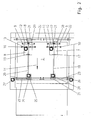
- FIG. 1 shows a sheet feeder 1 with a sheet stack 2 and 3 consisting of sheets 3 a downstream conveyor table 6 shown.
- the sheet stack 2 is on a stacking plate 11 positioned, which is arranged on lifting means 4.
- the lifting means 4 are operatively connected with a not shown, positioned in a frame 5 of the sheet feeder 1 Elevator.
- a first sheet separator 7 and a second sheet separator 8 are provided in the sheet feeder 1.
- Each sheet separator 7; 8 is provided with separating suction devices 9 and transport suction devices 10, which with in the direction of the width of the sheet 3 extending suction cups 12 and Transport suction carrier 13 are connected.
- the suction cups 12 are each with the Output member of a cam coupling transmission, not shown, connected to the suction cup carriers 12 and thus the suction cups 9 a cyclical movement between one lower rest position, in which the suction cups 9 sit on the sheet stack 2, and one upper locking position, which is shown approximately in Figure 1, impresses. Accordingly, everyone is Transport suction support 13 with the output member of a cam coupling gear, not shown connected, through which the transport suction devices 10 cyclically in a transport direction 14 and be moved in the opposite direction.
- the first sheet separator 7 is driven by a first drive 15 and the second sheet separator 8 associated with this driving second drive 16.
- the first scanning device 28 detects the Surface of the sheet stack 1 in the area of the first sheet separator 7, while with the second scanning device 29 the surface of the sheet stack 2 in the region of the second Sheet separator 8 is detected.
- the first sheet separator 7 is connected to a first longitudinal guide 19 by means of first lifting elements 17 and the second sheet separator 8 with the aid of second lifting elements 18 on a second one Longitudinal guide 20 arranged.
- On the longitudinal guides 19; 20 are the lifting elements 17; 18 and thus the sheet separator 7; 8 in or against the transport direction 14 independently slidably mounted from each other.
- the longitudinal guides 19; 20 as spindles formed, in which the lifting elements 17; 18 intervene.
- the first longitudinal guide 19 is in bearings 21 added.
- a bearing 21 is a rear transverse guide 22 and a Bearing 21 slidably associated with a front transverse guide 23.
- a first servomotor 24 is provided, which on the as Spindle trained first longitudinal guide 19 and by turning the first sheet separator 7 moves in or against the transport direction 14.
- the front transverse guide 23 is in the exemplary embodiment as a spindle mounted in the frame 5 formed, in which the bearing 21 engages, so that by a on the front transverse guide 23rd attacking and twisting this first adjusting means 26 of the first sheet separator 7 transverse to Transport direction 14 can be moved.
- the second longitudinal guide 20 is received in the bearing 21, the bearing 21 also displaceable a rear transverse guide 22 and a front transverse guide 23 assigned.
- a second Servomotor 25 is provided, which at the z. B. formed as a second longitudinal guide 20 attacks and by rotating the second sheet separator 8 in or against the transport direction 14 moves.
- the second longitudinal guide 20 and the front Transverse guide 23 associated bearing 21 can with the help of a designed as a spindle front transverse guide 23 engaging second actuating means 27 transverse to the transport direction 14 can be moved, the second sheet separator 8 following this movement.
- the longitudinal guides 19; 20 and the front cross guides 23 designed as spindles and the actuators 24; 25 and adjusting means 26, 27 are embodied as drive elements which implement a rotary movement. It is natural also possible, the adjusting movements of the sheet separator 7; 8 both in and against the Transport direction 14 and transversely thereto with the help of the sheet separators 7, 8 and to realize the bearings 21 attacking linear drives.
- the first drive 15 and the second drive 16 are with a control and regulating device 30 connected by means of a rotary angle encoder 31 with the downstream of the sheet feeder 1 Processing machine is linked.
- the first scanner 28 is over the Control and regulating device 30 with the first lifting elements 17 and the second scanning device 29 connected to the second lifting elements 18 via the control and regulating device 30.
- the first servomotor is also connected to the control and regulating device 30 24 and the second servomotor 25 as well as the first actuating means 26 and the second actuating means 27.
- An input device 32 is connected to the control and regulating device 30, through which the lifting elements 17; 18, servomotors 24; 25 and the adjusting means 26; 27 manually can be influenced. It is also possible to use the input device Enter 32 processing parameters in the control system 30 can be stored in order to realize an automated operation of the Sheet feeder 1.
- the first drive 15 and the second drive 16 are via the control device 30 driven with the inclusion of the signals generated by the angle encoder 31, so that they are synchronized with each other and in the work cycle of the downstream processing machine circulate.
- To implement synchronous operation of the drives 15; 16 is it z. B. possible to drive them according to the master-slave principle, one of the drives 15; 16 acts as a master and the other as a slave.
- the drives 15; 16 become the separating suction cups 12 and the transport suction cups 13 and thus the separating suction device 9 and the transport suction device 10 of the sheet separator 7; 8 driven.
- the top sheet 3 of the sheet stack 2 is by the Separating vacuum 9 isolated and handed over to the transport vacuum 10, which separated the Promote sheet 3 in transport direction 14 to the downstream processing machine.
- the scanners 28; 29, the surface of the sheet stack 2 is detected.
- About the Control and regulating device 30 and the lifting elements 17; 18 are the bow separators like this tracked in terms of their height level that their distance to the surface of the sheet stack 2 moves in a predetermined range. If sheet stack 2 is processed, whose surface is uneven, e.g. B. so-called hanging sheet stack 2, the height level the sheet separator 7; 8 changed independently of each other, so that a problem Processing of such a sheet stack 2 is possible.
- the sheet separators 7; 8 synchronous, i.e. H. each at the same time same path sections are moved in or against the transport direction 14.
- the format of the sheets to be processed is entered into the input device 32 3 entered and via the control and regulating device 30, the servomotors 24; 25 so controlled that the sheet separator 7; 8 on the longitudinal guides 19; 20 in one for the Processing format will be placed in optimal position, with the sheet separator 7; 8 synchronously with each other on the longitudinal guides 19; 20 are moved.
- the adjusting means 26; 27 controlled by the control and regulating device 30 and the longitudinal guides 19; 20 moved transversely to the transport direction 14, the position the sheet separator 7; 8 also optimally with regard to the format width to those that are processed Sheet 3 can be adjusted, the adjusting means 26; 27 are controlled so that the sheet separator 7; 8 the same path sections towards or from each other move away.
- first sheet stack 2.1 and a second one Sheet stacks 2.2 are provided, which can also have different formats.
- first sheet stack 2.1 which has a larger format length, is the first Sheet separator 7 and the second sheet stack 2.2 having a smaller format length assigned to the second sheet separator 8, the sheet separator 7; 8 using the servomotors 24; 25 the sheet stacks 2.1; 2.2 are assigned.
- the sheet stacks 2.1; 2.2 about the same format width on. But it is also possible to stack 2.1; 2.2 to process together the have different format widths. All that is required is the sheet separator 7; 8 by means of the adjusting means 26; 27 displacing the sheet stacks transversely to the transport direction 14 2.1; 2.2 adjust.
Landscapes
- Engineering & Computer Science (AREA)
- Mechanical Engineering (AREA)
- Sheets, Magazines, And Separation Thereof (AREA)
Abstract
Description
Bei großformatigen Bogenanlegern ist es bekannt, in der Formatbreite zwei Bogentrenner nebeneinander anzuordnen sowie die Antriebe dieser Bogentrenner mechanisch zu koppeln und als funktionelle Einheit zu betreiben, wobei eine Höhenstelleinrichtung vorgesehen ist, die, initiiert durch eine Stapelabtastung, das Höhenniveau dieser Einheit beeinflusst.
- Figur 1:
- einen Bogenanleger in der Seitenansicht
- Figur 2:
- eine Draufsicht auf den Bogenanleger nach Figur 1
- Figur 3:
- eine Ansicht gem. Figur 2 mit einer Steuer- und Regeleinrichtung
- Figur 4:
- eine Ansicht des Bogenanlegers gemäß Figur 1 von hinten
- Figur 5:
- einen Bogenanleger gem. Fig. 2 mit zwei Bogenstapeln
- Figur 6:
- den Bogenanleger nach Figur 5 von hinten.
- 1
- Bogenanleger
- 2
- Bogenstapel
- 2.1
- erster Bogenstapel
- 2.2
- zweiter Bogenstapel
- 3
- Bogen
- 4
- Hubmittel
- 5
- Gestell
- 6
- Bändertisch
- 7
- erster Bogentrenner
- 8
- zweiter Bogentrenner
- 9
- Trennsauger
- 10
- Transportsauger
- 11
- Stapelplatte
- 12
- Trennsaugerträger
- 13
- Transportsaugerträger
- 14
- Transportrichtung
- 15
- erster Antrieb
- 16
- zweiter Antrieb
- 17
- erstes Hubelement
- 18
- zweites Hubelement
- 19
- erste Längsführung
- 20
- zweite Längsführung
- 21
- Lager
- 22
- hintere Querführung
- 23
- vordere Querführung
- 24
- erster Stellmotor
- 25
- zweiter Stellmotor
- 26
- erstes Stellmittel
- 27
- zweites Stellmittel
- 28
- erste Abtasteinrichtung
- 29
- zweite Abtasteinrichtung
- 30
- Steuer- und Regeleinrichtung
- 31
- Drehwinkelgeber
- 32
- Eingabeeinrichtung
Claims (8)
- Bogenanleger zum Vereinzeln von Bogen mit einem ersten und einem zweiten Bogentrenner, die jeweils einen Trennsauger aufnehmenden Trennsaugerträger und einen Transportsauger aufnehmenden Transportsaugerträger sowie eine zugeordnete Bogentrennerhöhenverstellung aufweisen, wobei die Bogentrenner gemeinsam zur Formatanpassung in oder entgegen der Transportrichtung der Bogen verschiebbar sind, dadurch gekennzeichnet, dass dem ersten Bogentrenner (7) ein erster Antrieb (15) und dem zweiten Bogentrenner (8) ein zweiter Antrieb (16) zugeordnet ist und die Antriebe (15; 16) durch eine Steuer- und Regeleinrichtung (30) im Arbeitstakt einer nachgeordneten Verarbeitungsmaschine antreibbar sind, wobei die Bogentrenner (7; 8) unabhängig voneinander in oder entgegen der Transportrichtung (14) und/oder quer dazu verbringbar ausgeführt sind.
- Bogenanleger zum Vereinzeln von Bogen mit zwei Bogentrennern, die jeweils einen Trennsauger aufnehmenden Trennsaugerträger und einen Transportsauger aufnehmenden Transportsaugerträger sowie eine gemeinsame Bogentrennerhöhenabstellung aufweisen, wobei die Bogentrenner gemeinsam zur Formatanpassung in oder entgegen der Transportrichtung der Bogen verschiebbar sind, dadurch gekennzeichnet, dass dem ersten Bogentrenner (7) ein erster Antrieb (15) und dem zweiten Bogentrenner (8) ein zweiter Antrieb (16) zugeordnet ist und die Antriebe (15; 16) durch eine Steuer- und Regeleinrichtung (30) im Arbeitstakt einer nachgeordneten Verarbeitungsmaschine antreibbar sind, wobei die Bogentrenner (7; 8) in gleichen Wegabschnitten zu oder entgegen der Transportrichtung (14) und/oder quer dazu in gleichen Wegabschnitten aufeinander in oder voneinander weg verbringbar ausgeführt sind.
- Bogenanleger nach Anspruch 1 und 2, dadurch gekennzeichnet, dass der erste Bogentrenner (7) mittels eines ersten Stellmotors (24) auf einer ersten Längsführung (19) und der zweite Bogentrenner (8) mittels eines zweiten Stellmotors (25) auf einer zweiten Längsführung (20) verbringbar ausgeführt sind.
- Bogenanleger nach Anspruch 1, 2 und 3, dadurch gekennzeichnet, dass die erste Längsführung (19) mittels eines ersten Stellmittels (26) und die zweite Längsführung (20) mittels eines zweiten Stellmittels (27) quer zur Transportrichtung (14) verbringbar ausgeführt ist.
- Bogenanleger nach Anspruch 1, 2 und 3, dadurch gekennzeichnet, dass die Längsführungen (19, 20) als Spindeln ausgebildet sind.
- Bogenanleger nach Anspruch 1, 2, 3 und 4, dadurch gekennzeichnet, dass die Stellmotore (24, 25) und die Stellmittel (26, 27) als Linearmotore ausgebildet sind.
- Bogenanleger nach Anspruch 1 und 2, dadurch gekennzeichnet, dass dem ersten Bogentrenner (7) eine dessen Höhenlage erfassende erste Abtasteinrichtung (28) und dem zweiten Bogentrenner (8) und dessen Höhenlage erfassende zweite Abtasteinrichtung (29) zugeordnet ist und die erste Abtasteinrichtung (28) über die Steuer- und Regeleinrichtung (30) mit an dem ersten Bogentrenner (7) angreifenden ersten Hubelementen (17) und die zweite Ablasteinrichtung (29) über die Steuer- und Regeleinrichtung (30) mit an dem zweiten Bogentrenner (8) angreifenden zweiten Hubelementen (18) verbunden ist.
- Bogenanleger nach Anspruch 1 bis 7, dadurch gekennzeichnet, dass die Bogentrenner (7, 8) durch Eingeben der Formatgröße des Verarbeitungsgutes in eine der Steuer- und Regeleinrichtung (30) zugeordneten Eingabevorrichtung (32) positionierbar sind.
Applications Claiming Priority (2)
| Application Number | Priority Date | Filing Date | Title |
|---|---|---|---|
| DE10316361A DE10316361A1 (de) | 2003-04-10 | 2003-04-10 | Bogenanleger zum Vereinzeln von Bogen |
| DE10316361 | 2003-04-10 |
Publications (3)
| Publication Number | Publication Date |
|---|---|
| EP1466848A2 true EP1466848A2 (de) | 2004-10-13 |
| EP1466848A3 EP1466848A3 (de) | 2007-12-19 |
| EP1466848B1 EP1466848B1 (de) | 2011-02-23 |
Family
ID=32864412
Family Applications (1)
| Application Number | Title | Priority Date | Filing Date |
|---|---|---|---|
| EP04007420A Expired - Lifetime EP1466848B1 (de) | 2003-04-10 | 2004-03-26 | Bogenanleger zum Vereinzeln von Bogen |
Country Status (2)
| Country | Link |
|---|---|
| EP (1) | EP1466848B1 (de) |
| DE (2) | DE10316361A1 (de) |
Cited By (3)
| Publication number | Priority date | Publication date | Assignee | Title |
|---|---|---|---|---|
| EP3095740A1 (de) * | 2015-05-20 | 2016-11-23 | Ricoh Company, Ltd. | Trennvorrichtung für gefördertes material und fördervorrichtung für gefördertes material damit |
| EP3181499A1 (de) * | 2015-12-16 | 2017-06-21 | Ricoh Company, Ltd. | Blattmaterialzuführungsvorrichtung |
| CN119490090A (zh) * | 2023-08-21 | 2025-02-21 | 海德堡印刷机械股份公司 | 页张进料器的吸头机构控制 |
Families Citing this family (1)
| Publication number | Priority date | Publication date | Assignee | Title |
|---|---|---|---|---|
| DE102005001516B4 (de) * | 2005-01-13 | 2013-04-18 | manroland sheetfed GmbH | Bogenanleger |
Family Cites Families (7)
| Publication number | Priority date | Publication date | Assignee | Title |
|---|---|---|---|---|
| US2146945A (en) * | 1936-07-31 | 1939-02-14 | Ehrig Hans | Sheet feeder |
| US3391924A (en) * | 1966-07-29 | 1968-07-09 | Addressograph Multigraph | Sheet feeding mechanism |
| DE3919787A1 (de) * | 1989-06-16 | 1991-01-03 | Mabeg Maschinenbau Gmbh Nachf | Verfahren zum einrichten eines mit einem neuen bogenstapel versehenen bogenanlegers |
| DE9205400U1 (de) * | 1992-04-21 | 1992-06-11 | KBA-Planeta AG, O-8122 Radebeul | Vorrichtung zum Ausrichten von Bogen |
| DE19601470B4 (de) * | 1996-01-17 | 2004-10-28 | Heidelberger Druckmaschinen Ag | Schleppsaugergetriebe, insbesondere Schleppsaugergetriebe für eine Vorrichtung zur Schrägbogenkorrektur |
| DE19620937B4 (de) * | 1996-05-24 | 2004-08-05 | Man Roland Druckmaschinen Ag | Bogenanleger |
| DE19755521A1 (de) * | 1997-12-13 | 1999-06-17 | Koenig & Bauer Ag | Bogentrenner |
-
2003
- 2003-04-10 DE DE10316361A patent/DE10316361A1/de not_active Withdrawn
-
2004
- 2004-03-26 DE DE502004012215T patent/DE502004012215D1/de not_active Expired - Lifetime
- 2004-03-26 EP EP04007420A patent/EP1466848B1/de not_active Expired - Lifetime
Cited By (6)
| Publication number | Priority date | Publication date | Assignee | Title |
|---|---|---|---|---|
| EP3095740A1 (de) * | 2015-05-20 | 2016-11-23 | Ricoh Company, Ltd. | Trennvorrichtung für gefördertes material und fördervorrichtung für gefördertes material damit |
| EP3181499A1 (de) * | 2015-12-16 | 2017-06-21 | Ricoh Company, Ltd. | Blattmaterialzuführungsvorrichtung |
| TWI659918B (zh) * | 2015-12-16 | 2019-05-21 | 日商理光股份有限公司 | 片材供應裝置 |
| US10513404B2 (en) | 2015-12-16 | 2019-12-24 | Ricoh Company, Ltd. | Sheet-material supply device |
| CN119490090A (zh) * | 2023-08-21 | 2025-02-21 | 海德堡印刷机械股份公司 | 页张进料器的吸头机构控制 |
| CN119490090B (zh) * | 2023-08-21 | 2026-02-17 | 海德堡印刷机械股份公司 | 页张进料器的吸头机构控制 |
Also Published As
| Publication number | Publication date |
|---|---|
| EP1466848A3 (de) | 2007-12-19 |
| DE10316361A1 (de) | 2004-10-28 |
| DE502004012215D1 (de) | 2011-04-07 |
| EP1466848B1 (de) | 2011-02-23 |
Similar Documents
| Publication | Publication Date | Title |
|---|---|---|
| DE19758732B4 (de) | Vorrichtung zum Stapel von Büchern | |
| EP3326795A2 (de) | Vorrichtung zum verarbeiten von verpackungsmaterial sowie verfahren | |
| WO2018153695A1 (de) | Verfahren und vorrichtung zum stapeln von flächigen materialbogen sowie eine druck- und/oder lackiermaschine | |
| CH692700A5 (de) | Zusammentragmaschine. | |
| EP1466848B1 (de) | Bogenanleger zum Vereinzeln von Bogen | |
| DD201980A5 (de) | Zufuehreinrichtung fuer blechstreifenstapel | |
| EP3994087A1 (de) | Bogenbearbeitungsmaschine mit zumindest einer bogenablageeinrichtung und verfahren zur bogenablage | |
| EP4472811B1 (de) | Bearbeitungsmaschine und verfahren zum betreiben einer bearbeitungsmaschine | |
| EP1593626B1 (de) | Vorderkantenanleger | |
| DE10033490B4 (de) | Einrichtung zum seitlichen Ausrichten von Bogen | |
| EP1466850B1 (de) | Bogenanleger zum Vereinzeln von Bogen | |
| EP1466849A1 (de) | Bogenanleger zum Vereinzeln von Bogen | |
| EP1593625B1 (de) | Vorderkantenanleger | |
| EP1479492B1 (de) | Durchlaufmaschine für die Plattenbearbeitung mit einlaufseitiger Auflagervorrichtung | |
| EP1352862A2 (de) | Verfahren zum wahlweisen Zuführen von Bogen oder Vorlaufbogen | |
| WO2021083675A1 (de) | Bogenbearbeitungsmaschine mit zumindest einer bogenablageeinrichtung und verfahren zur bogenablage | |
| DE19720568C2 (de) | Einrichtung zum Zuführen von Bogen | |
| DE102024106245B4 (de) | Auslageaggregat und Verfahren zum Betrieb eines Auslageaggregats | |
| DE3150045A1 (de) | Zufuehreinrichtung fuer blechstreifenstapel zur zufuhr zu einem stanzautomaten | |
| DE10310696A1 (de) | Bogenanleger | |
| EP3907163A1 (de) | Anleger für stapel flächiger medien | |
| DE102023131908B4 (de) | Bearbeitungsmaschine | |
| EP0922658B1 (de) | Bogentrenner | |
| DE10310697A1 (de) | Bogenanleger | |
| DE102024119911A1 (de) | Ausrichteeinheit, Bearbeitungsmaschine und Verfahren zum Betrieb einer Ausrichteeinheit |
Legal Events
| Date | Code | Title | Description |
|---|---|---|---|
| PUAI | Public reference made under article 153(3) epc to a published international application that has entered the european phase |
Free format text: ORIGINAL CODE: 0009012 |
|
| AK | Designated contracting states |
Kind code of ref document: A2 Designated state(s): AT BE BG CH CY CZ DE DK EE ES FI FR GB GR HU IE IT LI LU MC NL PL PT RO SE SI SK TR |
|
| AX | Request for extension of the european patent |
Extension state: AL LT LV MK |
|
| PUAL | Search report despatched |
Free format text: ORIGINAL CODE: 0009013 |
|
| AK | Designated contracting states |
Kind code of ref document: A3 Designated state(s): AT BE BG CH CY CZ DE DK EE ES FI FR GB GR HU IE IT LI LU MC NL PL PT RO SE SI SK TR |
|
| AX | Request for extension of the european patent |
Extension state: AL LT LV MK |
|
| 17P | Request for examination filed |
Effective date: 20080220 |
|
| AKX | Designation fees paid |
Designated state(s): DE FR GB |
|
| 17Q | First examination report despatched |
Effective date: 20091014 |
|
| GRAP | Despatch of communication of intention to grant a patent |
Free format text: ORIGINAL CODE: EPIDOSNIGR1 |
|
| GRAC | Information related to communication of intention to grant a patent modified |
Free format text: ORIGINAL CODE: EPIDOSCIGR1 |
|
| GRAS | Grant fee paid |
Free format text: ORIGINAL CODE: EPIDOSNIGR3 |
|
| GRAA | (expected) grant |
Free format text: ORIGINAL CODE: 0009210 |
|
| AK | Designated contracting states |
Kind code of ref document: B1 Designated state(s): DE FR GB |
|
| REG | Reference to a national code |
Ref country code: GB Ref legal event code: FG4D Free format text: NOT ENGLISH |
|
| REF | Corresponds to: |
Ref document number: 502004012215 Country of ref document: DE Date of ref document: 20110407 Kind code of ref document: P |
|
| REG | Reference to a national code |
Ref country code: DE Ref legal event code: R096 Ref document number: 502004012215 Country of ref document: DE Effective date: 20110407 |
|
| PLBE | No opposition filed within time limit |
Free format text: ORIGINAL CODE: 0009261 |
|
| STAA | Information on the status of an ep patent application or granted ep patent |
Free format text: STATUS: NO OPPOSITION FILED WITHIN TIME LIMIT |
|
| 26N | No opposition filed |
Effective date: 20111124 |
|
| REG | Reference to a national code |
Ref country code: DE Ref legal event code: R097 Ref document number: 502004012215 Country of ref document: DE Effective date: 20111124 |
|
| REG | Reference to a national code |
Ref country code: FR Ref legal event code: PLFP Year of fee payment: 12 |
|
| PGFP | Annual fee paid to national office [announced via postgrant information from national office to epo] |
Ref country code: DE Payment date: 20150318 Year of fee payment: 12 |
|
| PGFP | Annual fee paid to national office [announced via postgrant information from national office to epo] |
Ref country code: FR Payment date: 20150319 Year of fee payment: 12 Ref country code: GB Payment date: 20150319 Year of fee payment: 12 |
|
| REG | Reference to a national code |
Ref country code: DE Ref legal event code: R119 Ref document number: 502004012215 Country of ref document: DE |
|
| GBPC | Gb: european patent ceased through non-payment of renewal fee |
Effective date: 20160326 |
|
| REG | Reference to a national code |
Ref country code: FR Ref legal event code: ST Effective date: 20161130 |
|
| PG25 | Lapsed in a contracting state [announced via postgrant information from national office to epo] |
Ref country code: GB Free format text: LAPSE BECAUSE OF NON-PAYMENT OF DUE FEES Effective date: 20160326 Ref country code: FR Free format text: LAPSE BECAUSE OF NON-PAYMENT OF DUE FEES Effective date: 20160331 Ref country code: DE Free format text: LAPSE BECAUSE OF NON-PAYMENT OF DUE FEES Effective date: 20161001 |