EP1466676B1 - Verfahren und Vorrichtung zum Herstellen eines geschlossenen Metallprofils oder Metallrohrs mit in Längsrichtung variierender Wanddicke - Google Patents
Verfahren und Vorrichtung zum Herstellen eines geschlossenen Metallprofils oder Metallrohrs mit in Längsrichtung variierender Wanddicke Download PDFInfo
- Publication number
- EP1466676B1 EP1466676B1 EP04006468A EP04006468A EP1466676B1 EP 1466676 B1 EP1466676 B1 EP 1466676B1 EP 04006468 A EP04006468 A EP 04006468A EP 04006468 A EP04006468 A EP 04006468A EP 1466676 B1 EP1466676 B1 EP 1466676B1
- Authority
- EP
- European Patent Office
- Prior art keywords
- roll forming
- sheet metal
- metal strip
- profile
- pipe
- Prior art date
- Legal status (The legal status is an assumption and is not a legal conclusion. Google has not performed a legal analysis and makes no representation as to the accuracy of the status listed.)
- Expired - Lifetime
Links
Images


Classifications
-
- B—PERFORMING OPERATIONS; TRANSPORTING
- B21—MECHANICAL METAL-WORKING WITHOUT ESSENTIALLY REMOVING MATERIAL; PUNCHING METAL
- B21C—MANUFACTURE OF METAL SHEETS, WIRE, RODS, TUBES, PROFILES OR LIKE SEMI-MANUFACTURED PRODUCTS OTHERWISE THAN BY ROLLING; AUXILIARY OPERATIONS USED IN CONNECTION WITH METAL-WORKING WITHOUT ESSENTIALLY REMOVING MATERIAL
- B21C37/00—Manufacture of metal sheets, rods, wire, tubes, profiles or like semi-manufactured products, not otherwise provided for; Manufacture of tubes of special shape
- B21C37/06—Manufacture of metal sheets, rods, wire, tubes, profiles or like semi-manufactured products, not otherwise provided for; Manufacture of tubes of special shape of tubes or metal hoses; Combined procedures for making tubes, e.g. for making multi-wall tubes
- B21C37/08—Making tubes with welded or soldered seams
- B21C37/0803—Making tubes with welded or soldered seams the tubes having a special shape, e.g. polygonal tubes
-
- B—PERFORMING OPERATIONS; TRANSPORTING
- B21—MECHANICAL METAL-WORKING WITHOUT ESSENTIALLY REMOVING MATERIAL; PUNCHING METAL
- B21C—MANUFACTURE OF METAL SHEETS, WIRE, RODS, TUBES, PROFILES OR LIKE SEMI-MANUFACTURED PRODUCTS OTHERWISE THAN BY ROLLING; AUXILIARY OPERATIONS USED IN CONNECTION WITH METAL-WORKING WITHOUT ESSENTIALLY REMOVING MATERIAL
- B21C37/00—Manufacture of metal sheets, rods, wire, tubes, profiles or like semi-manufactured products, not otherwise provided for; Manufacture of tubes of special shape
- B21C37/06—Manufacture of metal sheets, rods, wire, tubes, profiles or like semi-manufactured products, not otherwise provided for; Manufacture of tubes of special shape of tubes or metal hoses; Combined procedures for making tubes, e.g. for making multi-wall tubes
- B21C37/15—Making tubes of special shape; Making tube fittings
Definitions
- the invention relates to a method for producing a closed metal profile or metal tube whose wall thickness varies along its longitudinal axis, and a roll forming machine for carrying out the method, see e.g. EP-A-0 938 937.
- Roll forming machines and methods of roll forming sheet metal strips are used to manufacture of closed metal profiles or metal pipes although for a long time and widely used; however, it has only been possible to date metal profiles or Produce metal tubes whose wall thickness along its longitudinal axis constant remains.
- the invention is therefore based on the object, not only profiles with constant Wall thickness or with varying only in their cross-section wall thicknesses by roll forming, but also profiles and tubes in the longitudinal direction varying wall thickness.
- the inventive method thus consists in its core of the following Process steps: First, what in the prior art considered impossible or at least very detrimental and undesirable was a sheet metal strip with varying thickness along its length used and a Rollumformstrom supplied with roll forming tools, where there is a Profile or tube is reshaped. Before now that produced by the forming Profile or pipe in a conventional manner in a welding station longitudinal to a closed profile or tube is processed, the formed Profile or pipe in a completely new intermediate step on given Outside dimensions calibrated by means of at least one KalibrierrollenPaars. This calibration may well have the profile or pipe already on bring the desired final external dimensions, but this is not necessary is.
- the inventively modified Rollumformstrom for performing the just described method is characterized accordingly by the fact that at least a Kalibrierrollen pair between the roll forming tools and the Welding station is arranged to enable the novel "Zwischenkalibrieren" to enable perform the conventional longitudinal welding.
- the Wall thickness of the sheet metal strip used not only in the longitudinal direction, but additionally also varies along its cross section, so that the invention produced profiles and tubes in terms of material costs exactly for the respective application can be optimized.
- the calibration rollers are preferably arranged in unusual orientation. Normally a pipe or a closed profile runs during end calibration after the welding station so through the calibration rollers that the Weld seam runs centrally through one of the two calibration rollers. According to the present This invention should not be the case; is particularly preferred rather, an arrangement of the calibrating rollers in which the (according to the invention not yet existing) weld in the edge area between the two Calibration rolls comes to rest.
- the profile or pipe should be like that be guided through the calibration rollers that the connection plane between the longitudinal center axis of the profile or tube and the midline between the Narrow sides of the sheet metal strip different from the plane of rotation of the Kalibrierrollen is, preferably approximately at right angles to this. This has the following advantages:
- a sheet metal strip is used in which the sections of different Band thickness are set together so that the bands of the different sections each lie together.
- the neutral fiber at Forming is then always in the middle of the material, what the shear stresses advantageously minimized between the different sheet thicknesses.
- the outside dimensions are equalized, so that the fat jump then ultimately lies inside the pipe or profile.
- the forming of the sheet metal strip can be carried out by means of roll forming tools which form a nip, cooperating in pairs, wherein the inside width of the roll gap corresponding to the strip thickness of the moment therein section of the sheet metal strip is varied.
- This can by a positionally variable training one of two pairwise cooperating Rollformtechnikzeugmaschineen be achieved, this preferably is moved perpendicular to the longitudinal direction of the sheet metal strip.
- variable in order to vary the roll gap trained rollforming tools with a motorized, hydraulic or provided pneumatic adjustment mechanism or they are spring loaded formed variable in position, so that they are self-acting on the thickness set the currently located therein section of the sheet metal strip.
- the movements of the storable roll forming tools can accordingly the course of the thickness of the sheet metal strip are actively controlled, for example by means of a computer, in which the thickness of the sheet metal strip is stored during the production progress preferably over a Wegdorfnmess Rhein is reported to the computer, or for example corresponding to that of a sensor unit for measuring strip thickness measured values; the movements of the positionally variable roll forming tools but can also passively by a spring load or for example by means of an overpressure limitation of a hydraulic adjusting mechanism be achieved:
- the variable position rollforming tool then gives against the Spring force or due to the overpressure limitation after, when the sheet metal strip thickened in the nip, while the nip then also automatically again narrowed as the intermediate strip thickness decreases.
- the Rollumformstrom each Blechbandtop may additionally be provided, the Rollumformstrom each Blechbandtop facing adjust automatically, without it being necessary, before any Store data in the controller or install a complex sensor system.
- Figure 1 shows schematically the view of a frame 1, in which at an upper Drive shaft 2, an upper roll forming tool 3 and a lower drive shaft 4, a lower roll forming tool 5 are mounted.
- a cooperating Roll forming tools 3, 5 formed nip 6 is an already partially profiled sheet metal strip 7 to recognize.
- a roll forming machine according to the invention usually consists of a large number of such, one behind the other arranged racks, wherein the roll forming tools the respective forming step adapted differently.
- the peculiarity of the illustrated frame 1 is that the upper drive shaft 2 is not firmly seated on the frame 1, but stored vertically adjustable is.
- two hydraulic cylinder units 8a and 8b are provided which on the one hand on the frame 1 and on the other hand on the bearings 9a, 9b of the upper Support drive shaft 2.
- These are double-acting hydraulic cylinders, with which a defined change in height of the upper drive shaft 2 and thus a defined setting of the roll gap 6 can be achieved.
- the hydraulic circuit of the hydraulic cylinders 8a, 8b is schematic in FIG shown.
- the hydraulic cylinders 8 are from a pump 10 via a check valve 11 and a two-way valve 12 supplied with hydraulic oil.
- the Two-way valve 12 allows a reversal of the hydraulic cylinder 8: Will the line A is pressurized, the upper drive shaft 2 adjusted up to an upper stop and thus to a maximum opening of the roll gap 6; is achieved by actuating the two-way valve 12, as shown in Figure 1, the line B pressurized, the drive shaft 2 lowers to a bottom stop, allowing the nip 6 to its smallest extent closes.
- the two-way valve 12 thus allows in cooperation with the double-acting hydraulic cylinders 8, the active control described above of the roll gap 6, which is particularly sufficient, in particular only two different sheet metal strip thicknesses are processed.
- the upper roll forming tool 3 yields by the upper drive shaft 2 moves upward, and that until the hydraulic pressure in line B is again below the threshold for actuation of the pressure relief valve 13 decreases.
- the pump 10 then ensures that the hydraulic pressure does not drop further and thus the rolling pressure between the Roll Forming Tools 3 and 5 is maintained. If conversely that Sheet metal strip 7 in the nip 6 becomes thinner, the constructed by the pump 10 provides hydraulic pressure in the line B for the upper drive shaft 2 is moved down immediately, so that the nip 6 between the upper roll forming tool 3 and the lower roll forming tool 5 accordingly closes.
- the illustrated in Figure 1 hydraulic adjustment mechanism thus combines an active control of the roll gap opening by means of the two-way valve 12 with an automatic control of the rolling pressure by means of the pressure relief valve 13.
- the change of the roll gap 6 via an active reversal make the two-way valve 12, possibly also in addition for automatic roller pressure control.
- the pressure relief valve takes over 13 in active control mode regardless of the possibility of a Regulation of the rolling pressure a safety function against impermissible pressures in the hydraulic system.
- FIG. 2 shows a schematic view of a sheet metal strip by means of roll forming cylindrical tube 18 made of three different thicknesses.
- a first portion 15 has a thicker wall thickness, so that the band edges lying on bump.
- a second section 15 'associated with the first section 15 is welded in the center, has a smaller wall thickness, which is why the here Band edges are not on impact, but a gap remains, which is a simple Longitudinal welding makes it impossible to close the tube 18.
- a third portion 15 is welded, the again has the same wall thickness as the first section 15th
- FIG. 2 thus shows the situation before the calibration according to the invention and FIG Longitudinal welding for finishing the tube 18.
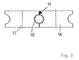
- a Kalibrierrollencover 16, 17 is now shown schematically, in which the tube 18 of Figure 2 is intermediately calibrated prior to welding.
- the abutting edge 19, ie the subsequent weld, lies in the edge area between the two calibration rollers 16 and 17; the connection plane between the abutting edge 19 and the longitudinal center axis of the tube 18 is thus perpendicular to the Plane of rotation of the two calibration rollers 16 and 17.
Landscapes
- Engineering & Computer Science (AREA)
- Mechanical Engineering (AREA)
- Bending Of Plates, Rods, And Pipes (AREA)
- Metal Extraction Processes (AREA)
Description
- Figur 1
- eine schematische Darstellung eines Gestells mit Rollformwerkzeugen in erfindungsgemäßer Ausführung nebst schematischer Darstellung eines hydraulischen Verstellmechanismus;
- Figur 2
- eine schematische Darstellung eines durch Rollumformen hergestellten zylindrischen Rohrs mit drei Abschnitten unterschiedlicher Wanddicke;
- Figur 3
- eine schematische Darstellung eines Kalibrierrollenpaars mit durchlaufendem Rohr.
- 1
- Gestell
- 2
- Antriebswelle (obere)
- 3
- Rollformwerkzeug (oberes)
- 4
- Antriebswelle (untere)
- 5
- Rollformwerkzeug (unteres)
- 6
- Walzspalt
- 7
- Blechband
- 8
- Hydraulikzylinder
- 9
- Lager (von 2)
- 10
- Pumpe
- 11
- Rückschlagventil
- 12
- Zweiwegeventil
- 13
- Überdruckventil
- 14
- Druckmesseinrichtung
- 15, 15', 15"
- Abschnitt (von 18)
- 16
- Kalibrierrolle
- 17
- Kalibrierrolle
- 18
- Rohr
- 19
- Stoßkante
Claims (20)
- Verfahren zum Herstellen eines geschlossenen Metallprofils oder Metallrohrs, dessen Wanddicke entlang seiner Längsachse variiert, mit folgenden Verfahrensschritten:Umformen eines Blechbandes (7) mit entlang seiner Länge variierender Banddicke mittels Rollformwerkzeugen (3, 5) zu einem Profil oder Rohr (18),Kalibrieren des Profils oder Rohrs (18) in mindestens einem Kalibrierrollenpaar (16, 17) auf vorgegebene Außenmaße,Zusammenschweißen der durch das Umformen und Kalibrieren aneinanderliegenden Schmalseiten des Blechbandes, um ein geschlossenes Profil oder Rohr fertigzustellen.
- Verfahren nach Anspruch 1,
dadurch gekennzeichnet, dass das Profil oder Rohr so durch die Kalibrierrollen geführt wird, dass die Verbindungsebene zwischen der Längs-Mittelachse des Profils oder Rohrs und der Mittellinie zwischen den Kanten des Blechbandes von der Rotationsebene der Kalibrierrollen verschieden ist. - Verfahren nach Anspruch 2,
dadurch gekennzeichnet, dass die Verbindungsebene zwischen der Längs-Mittelachse des Profils oder Rohrs und der Mittellinie zwischen den Kanten des Blechbandes in etwa rechtwinklig auf die Rotationsebene der Kalibrierrollen gestellt wird. - Verfahren nach einem der Ansprüche 1 bis 3,
dadurch gekennzeichnet, dass ein Blechband verwendet wird, bei dem die Abschnitte unterschiedlicher Banddicke so aneinandergesetzt sind, dass die Bandmitten der verschiedenen Abschnitte jeweils aneinander liegen. - Verfahren nach einem der Ansprüche 1 bis 4,
dadurch gekennzeichnet, dass das Umformen des Blechbandes zu einem Profil oder Rohr mittels Rollformwerkzeugen vorgenommen wird, die paarweise zusammenwirkend jeweils einen Walzspalt bilden, dessen lichte Weite entsprechend der Banddicke des momentan darin befindlichen Abschnitts des Blechbandes variiert wird. - Verfahren nach Anspruch 5,
dadurch gekennzeichnet, dass sich die Walzspalte aufgrund einer Verwendung von Rollformwerkzeugen, bei denen mindestens eines von zwei paarweise zusammenwirkenden Rollformwerkzeugen motorisch, federbelastet, hydraulisch oder pneumatisch Lageveränderlich ausgebildet ist, automatisch auf die Dicke des momentan darin befindlichen Abschnitts des Blechbandes einstellen. - Verfahren nach Anspruch 6,
dadurch gekennzeichnet, dass die lageveränderlichen Rollformwerkzeuge pneumatisch oder hydraulisch vorgespannt und/oder verstellt werden. - Verfahren nach Anspruch 6,
dadurch gekennzeichnet, dass die Bewegungen der lageveränderlichen Rollformwerkzeuge entsprechend dem Verlauf der Dicke des Blechbandes aktiv gesteuert werden. - Verfahren nach Anspruch 8,
dadurch gekennzeichnet, dass die Bewegungssteuerung mittels eines Computers erfolgt, in welchem der Dickenverlauf des Blechbandes eingespeichert ist, wobei der Produktionsfortschritt über eine Weglängenmesseinrichtung an den Computer gemeldet wird. - Verfahren nach einem der Ansprüche 8 oder 9,
dadurch gekennzeichnet, dass die Bewegung der lageveränderlichen Rollformwerkzeuge entsprechend den von einer oder mehreren Sensoreinheiten zur Banddickenmessung gemessenen Werten gesteuert wird. - Rollumformanlage zur Durchführung des Verfahrens nach Anspruch 1,
mit einer Mehrzahl von Rollformwerkzeugen (3, 5) zum Umformen eines Blechbandes (7) zu einem Metallprofil oder Metallrohr (18),
mit einer Schweißstation zum Längsverschweißen des umgeformten Blechbandes (7) zu einem geschlossenen Metallprofil oder Metallrohr (18),
und mit mindestens einem Paar Kalibrierrollen (16, 17) zum Kalibrieren des Profils oder Rohrs (18) auf vorgegebene Außenmaße,
dadurch gekennzeichnet, dass die Kalibrierrollen (16, 17) zwischen den Rollformwerkzeugen (3, 5) und der Schweißstation angeordnet sind. - Rollumformanlage nach Anspruch 11,
dadurch gekennzeichnet, dass die Kalibrierrollen (16, 17) so angeordnet sind, dass die Verbindungsebene zwischen der Längs-Mittelachse des Profils oder Rohrs (18) und der Mittellinie zwischen den Kanten (19) des Blechbandes (7) von der Rotationsebene der Kalibrierrollen (16, 17) verschieden ist. - Rollumformanlage nach Anspruch 12,
dadurch gekennzeichnet, dass die Verbindungsebene zwischen der Längs-Mittelachse des Profils oder Rohrs (18) und der Mittellinie zwischen den Kanten (19) des Blechbandes (7) im wesentlichen senkrecht auf der Rotationsebene der Kalibrierrollen (16) steht. - Rollumformanlage nach einem der Ansprüche 11 bis 13,
dadurch gekennzeichnet, dass zumindest ein Teil der Rollformwerkzeuge (5, 6) paarweise zusammenwirkend angeordnet sind, so dass sie jeweils einen Walzspalt (6) zum gleichzeitigen Einwirken auf das durch die Rollformwerkzeuge (3, 5) geführte Blechband (7) bilden, wobei jeweils mindestens eines von zwei paarweise zusammenwirkenden Rollformwerkzeugen (3) zur Anpassung des Walzspaltes (6) an eine variierende Dicke des Blechbandes (7) während des Umformprozesses relativ zum jeweils zugeordneten Rollformwerkzeug (5) lageveränderlich ausgebildet ist. - Rollumformanlage nach Anspruch 14,
dadurch gekennzeichnet, dass die lageveränderlichen Rollformwerkzeuge (3) federbelastet lageveränderlich ausgebildet sind. - Rollumformanlage nach einem der Ansprüche 14 oder 15,
dadurch gekennzeichnet, dass die lageveränderlichen Rollformwerkzeuge (3) mit einem motorischen, hydraulischen oder pneumatischen Verstellmechanismus (8) versehen sind. - Rollumformanlage nach Anspruch 16,
dadurch gekennzeichnet, dass der Verstellmechanismus (8) mit einer Überdruckbegrenzung (13) für den Walzdruck versehen ist. - Rollumformanlage nach einem der Ansprüche 16 oder 17,
dadurch gekennzeichnet, dass der Verstellmechanismus (8) mit einer Steuerung zum Verstellen des Walzspaltes (6) in Abhängigkeit von der variierenden Dicke des Blechbandes (7) versehen ist. - Rollumformanlage nach Anspruch 18,
dadurch gekennzeichnet, dass die Steuerung einen Speicher umfasst, in dem der Dickenverlauf des Blechbandes (7) hinterlegt ist. - Rollumformanlage nach Anspruch 18,
dadurch gekennzeichnet, dass die Steuerung des Verstellmechanismus (8) mit einer Sensoreinheit zur Banddickenmessung verbunden ist.
Applications Claiming Priority (2)
| Application Number | Priority Date | Filing Date | Title |
|---|---|---|---|
| DE10316336 | 2003-04-10 | ||
| DE10316336A DE10316336A1 (de) | 2003-04-10 | 2003-04-10 | Verfahren und Vorrichtung zum Herstellen eines geschlossenen Metallprofils oder Metallrohrs mit in Längsrichtung variierender Wanddicke |
Publications (2)
| Publication Number | Publication Date |
|---|---|
| EP1466676A1 EP1466676A1 (de) | 2004-10-13 |
| EP1466676B1 true EP1466676B1 (de) | 2005-10-12 |
Family
ID=32864409
Family Applications (1)
| Application Number | Title | Priority Date | Filing Date |
|---|---|---|---|
| EP04006468A Expired - Lifetime EP1466676B1 (de) | 2003-04-10 | 2004-03-18 | Verfahren und Vorrichtung zum Herstellen eines geschlossenen Metallprofils oder Metallrohrs mit in Längsrichtung variierender Wanddicke |
Country Status (6)
| Country | Link |
|---|---|
| US (1) | US20040245321A1 (de) |
| EP (1) | EP1466676B1 (de) |
| AT (1) | ATE306334T1 (de) |
| CA (1) | CA2464912A1 (de) |
| DE (2) | DE10316336A1 (de) |
| ES (1) | ES2250936T3 (de) |
Families Citing this family (5)
| Publication number | Priority date | Publication date | Assignee | Title |
|---|---|---|---|---|
| US9033398B2 (en) * | 2010-03-29 | 2015-05-19 | GM Global Technology Operations LLC | Multi-thickness tube for hydroformed members |
| EP4146420A4 (de) | 2020-05-05 | 2024-06-05 | Advanced Magnet Lab, Inc. | Verfahren zur kontinuierlichen herstellung von dauermagneten |
| CN112605124B (zh) * | 2020-11-27 | 2022-07-05 | 苏州吉润汽车零部件有限公司 | 一种连续变截面薄钢板的轧制设备及成型方法 |
| AU2022208708A1 (en) | 2021-01-14 | 2023-07-20 | Advanced Magnet Lab, Inc. | Electrical machines using axially-magnetized curvilinear permanent magnets |
| CN115155933B (zh) * | 2022-07-14 | 2023-06-09 | 润达光伏盐城有限公司 | 一种光伏组件生产用的腰形焊带校直、涂覆装置 |
Family Cites Families (13)
| Publication number | Priority date | Publication date | Assignee | Title |
|---|---|---|---|---|
| US3858785A (en) * | 1971-12-30 | 1975-01-07 | Olin Corp | Apparatus for making heat exchanger tube |
| US3861462A (en) * | 1971-12-30 | 1975-01-21 | Olin Corp | Heat exchange tube |
| US4047411A (en) * | 1977-01-03 | 1977-09-13 | The Boeing Company | Numerically controlled pyramid roll forming machine |
| US4317350A (en) * | 1978-11-20 | 1982-03-02 | E. W. Sivachenko | Corrugated plate having variable material thickness and method for making same |
| US4603806A (en) * | 1983-08-11 | 1986-08-05 | Nippon Steel Corporation | Method of manufacturing metal pipe with longitudinally differentiated wall thickness |
| US5720195A (en) * | 1995-11-17 | 1998-02-24 | Abbey Etna Machine Company | Lower forming roll removal and replacement structure |
| DE19604357B4 (de) * | 1996-02-07 | 2004-06-24 | Benteler Ag | Verfahren zur Herstellung von Rohren mit Abschnitten unterschiedlicher Wanddicke |
| US5887472A (en) * | 1997-06-23 | 1999-03-30 | Abbey Etna Machine Company | Tooling changeover for tube mills |
| DE19807830B4 (de) * | 1998-02-26 | 2005-10-20 | Vaw Alutubes Gmbh | Verfahren zur Herstellung von Karosserie- und Fahrwerkteilen für Fahrzeuge |
| DE19834400C1 (de) * | 1998-07-30 | 2000-01-05 | Dreistern Werk Maschinenbau Gm | Verfahren und Vorrichtung zum Herstellen eines Rohres, insbesondere für ein Rohr mit geringer Wandstärke, aus metallischem Bandmaterial mit relativ kleinem Durchmesser |
| DE19852462A1 (de) * | 1998-11-13 | 2000-05-25 | Welser Ohg Josef | Verfahren zum Herstellen eines Profils unterschiedlicher Wandstärke |
| DK1210998T3 (da) * | 2000-12-01 | 2004-11-01 | Dreistern Werk Maschinenbau Gmbh & Co Kg | Fremgangsmåde og anlæg til fremstilling af et metalprofil |
| US6527056B2 (en) * | 2001-04-02 | 2003-03-04 | Ctes, L.C. | Variable OD coiled tubing strings |
-
2003
- 2003-04-10 DE DE10316336A patent/DE10316336A1/de not_active Withdrawn
-
2004
- 2004-03-18 DE DE502004000095T patent/DE502004000095D1/de not_active Expired - Lifetime
- 2004-03-18 EP EP04006468A patent/EP1466676B1/de not_active Expired - Lifetime
- 2004-03-18 ES ES04006468T patent/ES2250936T3/es not_active Expired - Lifetime
- 2004-03-18 AT AT04006468T patent/ATE306334T1/de active
- 2004-04-08 CA CA002464912A patent/CA2464912A1/en not_active Abandoned
- 2004-04-12 US US10/822,628 patent/US20040245321A1/en not_active Abandoned
Also Published As
| Publication number | Publication date |
|---|---|
| ES2250936T3 (es) | 2006-04-16 |
| EP1466676A1 (de) | 2004-10-13 |
| DE10316336A1 (de) | 2004-11-04 |
| DE502004000095D1 (de) | 2006-02-23 |
| ATE306334T1 (de) | 2005-10-15 |
| CA2464912A1 (en) | 2004-10-10 |
| US20040245321A1 (en) | 2004-12-09 |
Similar Documents
| Publication | Publication Date | Title |
|---|---|---|
| EP1781429B1 (de) | Verfahren zum richten eines metallbandes und richtmaschine | |
| DE3529160C2 (de) | ||
| DE1940341C3 (de) | Verfahren und Einrichtung zum Herstellen von Metalleisten, insbesonder von rohrförmigen Schweißelektroden, aus einem Stabmaterial | |
| EP0454619A1 (de) | Zum Zylindrisch-Biegen einer Platte dienende Umformmaschine | |
| DE4310547C2 (de) | Verfahren und Vorrichtung zum Verhindern der seitlichen Verbiegung einer sich längs erstreckenden, gewalzten Bramme | |
| EP0112969B2 (de) | Verfahren zum Walzen von Metallbändern | |
| EP3820631B1 (de) | Erweiterte regelung jco-formpresse | |
| DE19834400C1 (de) | Verfahren und Vorrichtung zum Herstellen eines Rohres, insbesondere für ein Rohr mit geringer Wandstärke, aus metallischem Bandmaterial mit relativ kleinem Durchmesser | |
| DE2532710A1 (de) | Walzwerk zur herstellung nahtloser stahlrohre | |
| EP2694228A1 (de) | Blechbiegemaschine, verwendung einer solchen zur herstellung von schlitzrohren sowie verfahren zur formung eines bleches zu einem schlitzrohr | |
| DE3128055C2 (de) | Schrägwalzgerüst ohne Dorn für nahtlose Metallrohre | |
| EP1448323B1 (de) | Vorrichtung zur herstellung eines rohres | |
| EP2559497A2 (de) | Verfahren und Vorrichtung zum Herstellen kalt gepilgerter Rohre | |
| EP1466676A1 (de) | Verfahren und Vorrichtung zum Herstellen eines geschlossenen Metallprofils oder Metallrohrs mit in Längsrichtung variierender Wanddicke | |
| DE69109945T2 (de) | Umkehrbares Walzverfahren. | |
| EP4405119B1 (de) | Richtmaschine sowie verfahren zum richten | |
| EP3782746B1 (de) | Profil-richtapparat für eine profilieranlage und verfahren zum korrigieren von axialen abweichungen eines metallprofils | |
| EP1080800B1 (de) | Verfahren zum flexiblen Walzen eines Metallbandes | |
| EP3097992A1 (de) | Verfahren zum stufenwalzen eines metallbandes | |
| DE3245031C2 (de) | ||
| DE3028211C2 (de) | Walzstraße zum Streckreduzieren von Rohren | |
| EP0703014B1 (de) | Verfahren zum Walzen von Hohlblöcken auf einem Asselwalzwerk | |
| EP1669141B1 (de) | Verfahren zur Regelung des Querschnitts von aus einer Drahtwalzstrasse austretenden Drähten und Drahtwalzstrasse | |
| EP2419227B1 (de) | Biegepresse für blechtafeln | |
| EP3174647B1 (de) | Verfahren zur herstellung von warmgewalzten nahtlosen rohren mit verdickten enden |
Legal Events
| Date | Code | Title | Description |
|---|---|---|---|
| PUAI | Public reference made under article 153(3) epc to a published international application that has entered the european phase |
Free format text: ORIGINAL CODE: 0009012 |
|
| AK | Designated contracting states |
Kind code of ref document: A1 Designated state(s): AT BE BG CH CY CZ DE DK EE ES FI FR GB GR HU IE IT LI LU MC NL PL PT RO SE SI SK TR |
|
| AX | Request for extension of the european patent |
Extension state: AL LT LV MK |
|
| 17P | Request for examination filed |
Effective date: 20041109 |
|
| GRAP | Despatch of communication of intention to grant a patent |
Free format text: ORIGINAL CODE: EPIDOSNIGR1 |
|
| AKX | Designation fees paid |
Designated state(s): AT BE BG CH CY CZ DE DK EE ES FI FR GB GR HU IE IT LI LU MC NL PL PT RO SE SI SK TR |
|
| GRAS | Grant fee paid |
Free format text: ORIGINAL CODE: EPIDOSNIGR3 |
|
| GRAA | (expected) grant |
Free format text: ORIGINAL CODE: 0009210 |
|
| AK | Designated contracting states |
Kind code of ref document: B1 Designated state(s): AT BE BG CH CY CZ DE DK EE ES FI FR GB GR HU IE IT LI LU MC NL PL PT RO SE SI SK TR |
|
| PG25 | Lapsed in a contracting state [announced via postgrant information from national office to epo] |
Ref country code: CZ Free format text: LAPSE BECAUSE OF FAILURE TO SUBMIT A TRANSLATION OF THE DESCRIPTION OR TO PAY THE FEE WITHIN THE PRESCRIBED TIME-LIMIT Effective date: 20051012 Ref country code: FI Free format text: LAPSE BECAUSE OF FAILURE TO SUBMIT A TRANSLATION OF THE DESCRIPTION OR TO PAY THE FEE WITHIN THE PRESCRIBED TIME-LIMIT Effective date: 20051012 Ref country code: NL Free format text: LAPSE BECAUSE OF FAILURE TO SUBMIT A TRANSLATION OF THE DESCRIPTION OR TO PAY THE FEE WITHIN THE PRESCRIBED TIME-LIMIT Effective date: 20051012 Ref country code: GB Free format text: LAPSE BECAUSE OF FAILURE TO SUBMIT A TRANSLATION OF THE DESCRIPTION OR TO PAY THE FEE WITHIN THE PRESCRIBED TIME-LIMIT Effective date: 20051012 Ref country code: PL Free format text: LAPSE BECAUSE OF FAILURE TO SUBMIT A TRANSLATION OF THE DESCRIPTION OR TO PAY THE FEE WITHIN THE PRESCRIBED TIME-LIMIT Effective date: 20051012 Ref country code: SK Free format text: LAPSE BECAUSE OF FAILURE TO SUBMIT A TRANSLATION OF THE DESCRIPTION OR TO PAY THE FEE WITHIN THE PRESCRIBED TIME-LIMIT Effective date: 20051012 Ref country code: IE Free format text: LAPSE BECAUSE OF FAILURE TO SUBMIT A TRANSLATION OF THE DESCRIPTION OR TO PAY THE FEE WITHIN THE PRESCRIBED TIME-LIMIT Effective date: 20051012 Ref country code: RO Free format text: LAPSE BECAUSE OF FAILURE TO SUBMIT A TRANSLATION OF THE DESCRIPTION OR TO PAY THE FEE WITHIN THE PRESCRIBED TIME-LIMIT Effective date: 20051012 Ref country code: SI Free format text: LAPSE BECAUSE OF FAILURE TO SUBMIT A TRANSLATION OF THE DESCRIPTION OR TO PAY THE FEE WITHIN THE PRESCRIBED TIME-LIMIT Effective date: 20051012 |
|
| REG | Reference to a national code |
Ref country code: GB Ref legal event code: FG4D Free format text: NOT ENGLISH |
|
| REG | Reference to a national code |
Ref country code: CH Ref legal event code: EP |
|
| REG | Reference to a national code |
Ref country code: IE Ref legal event code: FG4D Free format text: LANGUAGE OF EP DOCUMENT: GERMAN |
|
| PG25 | Lapsed in a contracting state [announced via postgrant information from national office to epo] |
Ref country code: BG Free format text: LAPSE BECAUSE OF FAILURE TO SUBMIT A TRANSLATION OF THE DESCRIPTION OR TO PAY THE FEE WITHIN THE PRESCRIBED TIME-LIMIT Effective date: 20060112 Ref country code: SE Free format text: LAPSE BECAUSE OF FAILURE TO SUBMIT A TRANSLATION OF THE DESCRIPTION OR TO PAY THE FEE WITHIN THE PRESCRIBED TIME-LIMIT Effective date: 20060112 Ref country code: DK Free format text: LAPSE BECAUSE OF FAILURE TO SUBMIT A TRANSLATION OF THE DESCRIPTION OR TO PAY THE FEE WITHIN THE PRESCRIBED TIME-LIMIT Effective date: 20060112 Ref country code: GR Free format text: LAPSE BECAUSE OF FAILURE TO SUBMIT A TRANSLATION OF THE DESCRIPTION OR TO PAY THE FEE WITHIN THE PRESCRIBED TIME-LIMIT Effective date: 20060112 |
|
| REF | Corresponds to: |
Ref document number: 502004000095 Country of ref document: DE Date of ref document: 20060223 Kind code of ref document: P |
|
| PG25 | Lapsed in a contracting state [announced via postgrant information from national office to epo] |
Ref country code: PT Free format text: LAPSE BECAUSE OF FAILURE TO SUBMIT A TRANSLATION OF THE DESCRIPTION OR TO PAY THE FEE WITHIN THE PRESCRIBED TIME-LIMIT Effective date: 20060313 |
|
| PG25 | Lapsed in a contracting state [announced via postgrant information from national office to epo] |
Ref country code: MC Free format text: LAPSE BECAUSE OF NON-PAYMENT OF DUE FEES Effective date: 20060331 Ref country code: LU Free format text: LAPSE BECAUSE OF NON-PAYMENT OF DUE FEES Effective date: 20060331 |
|
| NLV1 | Nl: lapsed or annulled due to failure to fulfill the requirements of art. 29p and 29m of the patents act | ||
| PG25 | Lapsed in a contracting state [announced via postgrant information from national office to epo] |
Ref country code: HU Free format text: LAPSE BECAUSE OF FAILURE TO SUBMIT A TRANSLATION OF THE DESCRIPTION OR TO PAY THE FEE WITHIN THE PRESCRIBED TIME-LIMIT Effective date: 20060413 |
|
| REG | Reference to a national code |
Ref country code: ES Ref legal event code: FG2A Ref document number: 2250936 Country of ref document: ES Kind code of ref document: T3 |
|
| GBV | Gb: ep patent (uk) treated as always having been void in accordance with gb section 77(7)/1977 [no translation filed] |
Effective date: 20051012 |
|
| REG | Reference to a national code |
Ref country code: IE Ref legal event code: FD4D |
|
| ET | Fr: translation filed | ||
| PLBE | No opposition filed within time limit |
Free format text: ORIGINAL CODE: 0009261 |
|
| STAA | Information on the status of an ep patent application or granted ep patent |
Free format text: STATUS: NO OPPOSITION FILED WITHIN TIME LIMIT |
|
| 26N | No opposition filed |
Effective date: 20060713 |
|
| PG25 | Lapsed in a contracting state [announced via postgrant information from national office to epo] |
Ref country code: EE Free format text: LAPSE BECAUSE OF FAILURE TO SUBMIT A TRANSLATION OF THE DESCRIPTION OR TO PAY THE FEE WITHIN THE PRESCRIBED TIME-LIMIT Effective date: 20051012 |
|
| PG25 | Lapsed in a contracting state [announced via postgrant information from national office to epo] |
Ref country code: TR Free format text: LAPSE BECAUSE OF FAILURE TO SUBMIT A TRANSLATION OF THE DESCRIPTION OR TO PAY THE FEE WITHIN THE PRESCRIBED TIME-LIMIT Effective date: 20051012 |
|
| REG | Reference to a national code |
Ref country code: CH Ref legal event code: PL |
|
| PG25 | Lapsed in a contracting state [announced via postgrant information from national office to epo] |
Ref country code: CY Free format text: LAPSE BECAUSE OF FAILURE TO SUBMIT A TRANSLATION OF THE DESCRIPTION OR TO PAY THE FEE WITHIN THE PRESCRIBED TIME-LIMIT Effective date: 20051012 |
|
| PG25 | Lapsed in a contracting state [announced via postgrant information from national office to epo] |
Ref country code: LI Free format text: LAPSE BECAUSE OF NON-PAYMENT OF DUE FEES Effective date: 20080331 Ref country code: CH Free format text: LAPSE BECAUSE OF NON-PAYMENT OF DUE FEES Effective date: 20080331 |
|
| REG | Reference to a national code |
Ref country code: FR Ref legal event code: PLFP Year of fee payment: 13 |
|
| PGFP | Annual fee paid to national office [announced via postgrant information from national office to epo] |
Ref country code: ES Payment date: 20160322 Year of fee payment: 13 Ref country code: DE Payment date: 20160315 Year of fee payment: 13 |
|
| PGFP | Annual fee paid to national office [announced via postgrant information from national office to epo] |
Ref country code: FR Payment date: 20160322 Year of fee payment: 13 Ref country code: AT Payment date: 20160318 Year of fee payment: 13 Ref country code: BE Payment date: 20160322 Year of fee payment: 13 |
|
| PGFP | Annual fee paid to national office [announced via postgrant information from national office to epo] |
Ref country code: IT Payment date: 20160318 Year of fee payment: 13 |
|
| REG | Reference to a national code |
Ref country code: DE Ref legal event code: R119 Ref document number: 502004000095 Country of ref document: DE |
|
| REG | Reference to a national code |
Ref country code: AT Ref legal event code: MM01 Ref document number: 306334 Country of ref document: AT Kind code of ref document: T Effective date: 20170318 |
|
| REG | Reference to a national code |
Ref country code: FR Ref legal event code: ST Effective date: 20171130 |
|
| PG25 | Lapsed in a contracting state [announced via postgrant information from national office to epo] |
Ref country code: AT Free format text: LAPSE BECAUSE OF NON-PAYMENT OF DUE FEES Effective date: 20170318 Ref country code: FR Free format text: LAPSE BECAUSE OF NON-PAYMENT OF DUE FEES Effective date: 20170331 Ref country code: DE Free format text: LAPSE BECAUSE OF NON-PAYMENT OF DUE FEES Effective date: 20171003 |
|
| PG25 | Lapsed in a contracting state [announced via postgrant information from national office to epo] |
Ref country code: IT Free format text: LAPSE BECAUSE OF NON-PAYMENT OF DUE FEES Effective date: 20170318 |
|
| REG | Reference to a national code |
Ref country code: BE Ref legal event code: MM Effective date: 20170331 |
|
| PG25 | Lapsed in a contracting state [announced via postgrant information from national office to epo] |
Ref country code: BE Free format text: LAPSE BECAUSE OF NON-PAYMENT OF DUE FEES Effective date: 20170331 |
|
| REG | Reference to a national code |
Ref country code: ES Ref legal event code: FD2A Effective date: 20180703 |
|
| PG25 | Lapsed in a contracting state [announced via postgrant information from national office to epo] |
Ref country code: ES Free format text: LAPSE BECAUSE OF NON-PAYMENT OF DUE FEES Effective date: 20170319 |