EP1465137A2 - Plombenanordnung - Google Patents
Plombenanordnung Download PDFInfo
- Publication number
- EP1465137A2 EP1465137A2 EP04003577A EP04003577A EP1465137A2 EP 1465137 A2 EP1465137 A2 EP 1465137A2 EP 04003577 A EP04003577 A EP 04003577A EP 04003577 A EP04003577 A EP 04003577A EP 1465137 A2 EP1465137 A2 EP 1465137A2
- Authority
- EP
- European Patent Office
- Prior art keywords
- head
- plug
- arrangement according
- base body
- opening
- Prior art date
- Legal status (The legal status is an assumption and is not a legal conclusion. Google has not performed a legal analysis and makes no representation as to the accuracy of the status listed.)
- Granted
Links
Images






Classifications
-
- G—PHYSICS
- G09—EDUCATION; CRYPTOGRAPHY; DISPLAY; ADVERTISING; SEALS
- G09F—DISPLAYING; ADVERTISING; SIGNS; LABELS OR NAME-PLATES; SEALS
- G09F3/00—Labels, tag tickets, or similar identification or indication means; Seals; Postage or like stamps
- G09F3/02—Forms or constructions
- G09F3/03—Forms or constructions of security seals
- G09F3/0305—Forms or constructions of security seals characterised by the type of seal used
- G09F3/0347—Forms or constructions of security seals characterised by the type of seal used having padlock-type sealing means
- G09F3/0352—Forms or constructions of security seals characterised by the type of seal used having padlock-type sealing means using cable lock
Definitions
- the invention relates to a seal arrangement with a base body, a in a receptacle of the plug-in plug-in head and a plug-in head and basic body connecting flexible connecting link, wherein these elements typically together in one piece as a molded plastic part getting produced.
- seal arrangements are in particular as seals on container closures, for example, luggage containers used in air freight and should enable a simple check whether the sealed Container has remained unopened between sealing and inspection.
- a manipulation carried out on such a seal arrangement is said to both at the authorized breaking of the seal arrangement as well as at one Interim review can be identified without much effort.
- return manipulations on such seal devices are known again and again, which circumvent the security measures taken so that a Freight theft is not noticed or is noticed only late.
- a security seal in which Insert head and corresponding to a lock in a receptacle of the base body a plurality of interlocking toothings are formed.
- a ring collar covers the edges of the insertion opening and is thus intended to be inserted of tools between the receptacle and the insertion head to loosen the Prevent latching.
- a predetermined breaking point in the form of a reduction in cross-section the connecting link is on the side facing away from the insertion head of the ring collar provided.
- the connector is flexible as a thin Ribbon executed.
- a plastic seal known from AT 343 532 B contains a locking receptacle a separate insert part that can be used in the base body, in which two longitudinally spaced locks are formed are.
- the insertion part is in the receptacle of the base body, which is open on one side inserted in a latching manner and by means of the plug-in head which snaps into the locks locked in the body.
- DE 33 22 633 C2 describes a one-piece plastic seal, in which the link three essentially forming a rigid U-shape Leg and an articulated pivotable fourth leg, on which the Base body is arranged with the recording includes.
- the one on the first leg arranged plug-in head snaps behind spring hooks of a lock in the Basic body.
- With a similarly constructed seal from EP 0 786 753 B1 is the locking not an integral part of the base body itself, but on a spring steel bracket which is opposite to that of the insertion opening End opening is inserted into the base body, formed. The final opening is closed by a snap-in lid.
- Spring steel bracket and inserting head can also have two locking levels one after the other in the direction of insertion exhibit.
- EP 0 786 753 B1 shows a security seal with one receptacle, one Insert head and an articulated connecting link. The admission is through a body with one against the direction of insertion or from the side insert introduced with pawls.
- the locking is in the body also by one of the end opening of the receptacle forth used holding body formed, which is also the end opening closes.
- the present invention has for its object the security against manipulation to further improve such seal arrangements.
- first cross-sectional narrowing in the form of a first Bridge offers protection against a form of manipulation, in which a seal arrangement is separated and by inserting a pin, Wire or the like the separation point is repaired.
- Such at the Repairs carried out instead of the first cross-sectional narrowing would be visible or felt by a stick protruding into the free space and / or showed due to insufficient anchorage depth on the side of the stop element insufficient holding force.
- the thickness of the stop member in extension of the first cross-sectional constriction forming web and thus in the fictitious plug-in direction to be manipulated Repair of the pin to be used is advantageously less than 2 mm, in particular less than 1.5 mm.
- the thickness of the stop member is advantageous in the extension of the web small against the smallest transverse extension of the stop member perpendicular to the longitudinal direction and is preferably less than 30% of such smallest transverse expansion.
- the stop member can in particular be disc-shaped.
- the first web advantageously has a circumferential direction with respect to the longitudinal direction a feed transverse to the longitudinal direction against the stop member or its the surface facing the first web.
- the indentation is advantageously larger than the radius of the web in the same direction transverse to the longitudinal direction.
- the average dimension of the feed is preferably greater than the length of the first Bars in the longitudinal direction or at least larger than that in typical use of the locked seal arrangement accessible free length of the first web.
- the surface of the stop member facing the first web forms with the longitudinal direction preferably an angle of approximately 90 °.
- the link preferably continues from the stop member transversely to the longitudinal direction.
- the Connecting link forms on the side of the stop link facing away from the first web advantageously a bow, which is in direct extension of the web has a clearance immediately behind the stop member.
- the first web is advantageously delimited so that it faces away from the stop member through a cross-sectionally larger middle part, the cross section of which advantageously the typical or standardized cross-section of an opening a locking device to be sealed can be adapted.
- the transition advantageously takes place from the first web to such a middle part likewise over an at least approximately rectangular step.
- the first footbridge preferably has a constant cross section in the longitudinal direction.
- the section between the stop member and plug-in head or base body in The locked state of the seal arrangement is referred to as the locking section.
- Predetermined breaking point arranged at the transition facing away from the stop member Bolt section to the insertion head as a second cross-sectional constriction Predetermined breaking point arranged.
- the cross-sectional area of the predetermined breaking point is preferred at least 20% less than the cross-sectional area of the first Web.
- the insertion head is advantageously in itself DE 199 59 229 A1 known type within the receptacle of the base body displaceable in the longitudinal direction by a dimension that can be felt by the user. According to the invention it is provided that such a displaceability also recognizable to the user at a position facing away from the insertion opening is accessible without the plug head itself in this position is.
- an additional opening of the base body in the receptacle Inserted holding body provided, which is within the receptacle can be moved in the longitudinal direction together with the insertion head by a limited amount is and at the same time access to the plug-in head from the additional Prevents opening.
- a movement of the holding body and the insertion head is thus both on the side of the insertion opening in a movement of the connector carrying the plug head and on the side of End opening on the holding body or an element coupled thereto recognizable, especially visible and / or tactile.
- the displaceability of the holding body is preferably well above that for latching lock typical longitudinal tolerance, which is a reliable Locking ensures, and is advantageously at least 0.5 mm, in particular at least 1 mm.
- the displaceability of the holding body is advantageously at most 5 mm, in particular at most 3.5 mm.
- the plug-in head can still within the holding body against its displacement reduced dimension to be longitudinally movable.
- the common displaceability given an intact seal arrangement in the longitudinal direction for example, in a simple manner be checked that the basic body is held with one hand and with the other hand the connecting link in the longitudinal direction of the insertion head moved and at the same time visually or with the one holding the basic body The correlated movement of the holding body is checked by hand.
- the holding body is preferably pre-assembled in the base body in a fail-safe manner.
- a circumferential step or the like is formed be, which is also the introduction of manipulation tools by difficult at the end opening.
- the holding body can advantageously different, in particular assume any angular positions around the longitudinal direction.
- the mobility of the insertion head in the insertion direction is advantageous by a step on the section outside the insertion opening limited of the link which strikes the edge of the insertion opening. There is preferably a predetermined breaking point between the step and the insertion head intended.
- another lock for the plug-in head in the base body provided itself.
- a further displacement of the holding body can in the recording by the holder of the plug-in head in the holding body be effective.
- the holding body is in a end opening of the base body inserted opposite the insertion opening and guided in a longitudinally displaceable manner in the base body.
- the holding body advantageously contains an elastically expandable and snapping onto the base body Clip.
- the arrangement contains essentials Elements a basic body GK, a plug-in head EK, a Plug-in head connecting link VB and the base body a signal plug SS.
- Basic body GK, plug-in head EK and connecting link VB are preferably a one-piece plastic injection molded part executed.
- the connecting link points in its course in the sketched example a swivel joint SG, e.g. B. a plastic film hinge to which Base body and plug-in head for closing the seal arrangement are pivotable relative to each other.
- the connecting link can also be in itself be flexible. Such structures of a seal arrangement are known per se.
- the signal plug SS is available as a separate part, which but also captive with the one-piece via a thin flexible connection Plastic part made of EK, GK, VB can be connected.
- a Marking plate KP may be provided, which a marking, for. B. for individualizing an object sealed with the seal arrangement can carry. 1 is for simplified reference in the following figures added a rectangular coordinate system x, y, z.
- FIG. 2 shows the seal arrangement of FIG. 1 looking at the surface the identification plate KP, d. H. in the y direction.
- the identification plate can advantageously in a marking emphasizing background color, especially from the rest of the plastic part of different colors executed and preferably firmly in a two-step injection molding process the base body GK and / or a section AG of the connecting member connected, e.g. B. anchored by back injection of openings SL in section AG his.
- the connecting link VB is in the example outlined by the base body GK facing section AG and one leading to the EK insertion head Bracket BU formed, which are connected via the swivel joint SG.
- section AG and bracket BU are assumed to be essentially rigid in themselves, but can also be made flexible.
- bracket BU facing the insertion head
- Cross section with a flat web BS and a lying in the x-z plane have along this band BB lying perpendicular to the x-z plane.
- the cross-sectional constrictions from the transom section RA to the first and / or to the second web preferably take place abruptly.
- the length of the webs is advantageously small, so that attempts to repair it by welding the web severed during manipulation are very difficult.
- the cross-sectional area of the second web SB is advantageously much less, in particular at least 20% less than the cross-sectional area of the first web SA, so that when one tears open undamaged closed seal reliably the second web SB as a predetermined breaking point tears off and a tear on the second bridge indicates a manipulation can be on the seal.
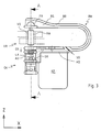
- the bracket BU acts as a stop element at the transition to the first web pushing the link through one of the locking portion solid opening VO of an object closure VR in FIG. 3 outlined closed state of the lead assembly, allowing tampering the seal arrangement for unauthorized opening only in the section between EK insertion head and BU bracket or by manipulating loosening the locking of the plug-in head in the receptacle of the base body is possible are.
- the direction of the longitudinal extension of the locking section RA and the plug-in head EK is labeled LR.
- the thickness of the stop element in the extension of the web small is.
- the thickness of the stop element in the extension of the first web SA is less than 2 mm, in particular less than 1.5 mm.
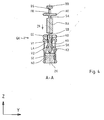
- the thickness of the stop member is preferably in extension of the first web SA (longitudinal direction LR in Fig. 2, z-direction in Fig. 3 and Fig. 4) small against the smallest transverse dimensions (y-z plane in Fig. 2, x-y plane in Fig. 3 and Fig. 4) of the stop element and is in particular less than 30% of these smallest transverse dimensions.
- the stop element According to the preferred embodiment outlined, it can advantageously be disk-shaped, in particular at least approximately as a circular disk his.
- the first web advantageously faces the surface of the Stop member in the x-y plane of Fig. 3 or Fig. 4 a clear on all sides Moving in to the connection point from the first web and stop element difficult to make accessible and attempted repairs by welding to prevent a split first bridge.
- the free space behind the stop element is preferably an extension of the first web formed by the bracket BU as a continuation Link bridges the stop link in an arc, which in Extension of the first web immediately behind the stop member Exemption FR forms.
- the exemption can advantageously in the Web BS of the bracket cross section can be formed, which for this purpose on this Site can have a greater height than in the predominant course of the Bracket BU.
- Another aspect of the present invention relates to locking of the plug-in head in the base body and in particular for a control option the integrity of this locking by means of a holding body, which within the base body between the insertion opening EE for the Plug-in head and an additional opening ZE lying receptacle AU for the insertion head is held on this.
- the holding body as a signal body for a limited longitudinal displacement of the plug-in head serves in the main body by the longitudinal displacement of the insertion head is connected to a longitudinal displacement of the holding body and the latter is visible and / or tactile for the user.
- the holding body which at the same time the closes additional opening in the base body, is in or on the base body Insertion direction of the insertion head (z direction in Fig.
- the Holding body can also act as a lock for the insertion head in the receptacle Serve AU.
- there is a lock in the base body itself formed for the plug-in head in particular in the form of or preferably several elastic when inserting the insertion head on the side more evasive and based on a narrowing of the insertion head Locking tongues or slats LA in a manner known per se.
- the plug-in head is in the closed position of the seal arrangement in the z-direction in a position in which the lamellae LA in the Base body formed after the insertion opening EE locking a first narrowing V1 of the insertion head EK between an input section KO of the insertion head and a wider compared to the narrowing first head section K1 against pulling out of the insertion head from the Support the base body.
- the area is as in FIG. 2 of the body is drawn transparently to show the essential elements.
- the input section KO of the plug-in head is in the example outlined essentially cylindrical in shape and with a small lateral gap against the insertion opening in this. Towards the first head section K1 the entrance section merges with a sloping flank. It is essential that the insertion head compared to that sketched in FIGS. 3 and 4 Position relative to the base body in the direction of insertion (z direction in Fig. 3, Fig. 4) is displaceable to a limited extent. The limitation of such Movability is preferably by striking the second Web SB given the following latch section RA on the base body GK. insertion EE and input section KO can also be designed in stages be if the longitudinal displaceability is given.
- the insertion opening EE in the insertion direction is the additional one Opening ZE arranged in the base body so that one with respect to an injection molding tool particularly advantageous shape of the base body is given.
- the receptacle formed between the insertion opening and the additional opening in The base body preferably has a circular cross section.
- the signal plug SS is inserted through the additional opening ZE in the base body.
- the signal plug is advantageously based on that of Basic body separate position according to FIG. 2 before closing the seal arrangement inserted into the additional opening ZE and is there advantageously due to the essentially cylindrical opening, Inner wall of the receptacle or protrusions Cam NO, which in a circumferential groove or recess SE on the circumference intervene, held.
- the cams and the clearance SE are on top of each other matched that the signal plug by a predetermined amount in the z direction remains movable.
- the cams NO are in the radial direction dimensioned that on the one hand the base body of the injection molded part without this Place moving parts of the injection mold out of it by forced demolding can be removed and the signal plug under elastic deformation of the base body can be snapped into this and that on the other hand the signal plug even when the seal arrangement is open is held in the main body in a fail-safe manner.
- the signal plug can in particular already pre-assembled in the base body of the receptacle.
- An end cap ZK of the signal plug closes the additional opening ZE of the Main body essentially completely, but is still in the recording guided longitudinally.
- the end cap closes in closed seal arrangement maximally in the receptacle of the base body inserted state essentially flush with the outlet opening ZE and can be moved by a limited amount when checking the plug-in head Dimension be pushed out of the basic body. This can the overall length of the base body in the z direction can be kept particularly small.
- the end cap ZK can be closed Seal arrangement maximally in the inserted state in the base body are also shifted inwards against the additional opening ZE.
- An essential element of the signal plug is a means of closing it State of the seal arrangement a connection between the signal plug and to produce the plug-in head, which is a control movement of the plug-in head transmits in the z direction on the signal plug.
- this is a two-legged on the side of the signal plug SS Clip with the clip opening facing the insertion opening EE.
- the clamp legs SK are inserted through the tip KS of the insertion head EK pressed apart elastically and snap behind the second Head section K2 in the second constriction V2.
- the second head section behind the hooks of the clamp legs hold the signal plug on the Tip of the insertion head with preferably little play in the z direction and thus couple the movement of the signal plug to the movement of the plug-in head in the y direction.
- the signal plug is advantageously around the longitudinal axis of the insertion head can be rotated in any angular position. That by reaching behind of the insertion head by the clamping leg SK applied holding force the signal plug on the plug-in head is advantageously larger than that force required to tear off the predetermined breaking point, which is caused by shaping the Hook the clasp legs and the shoulder of the Head section K2 and the material cross-sections of the individual elements can be ensured. This prevents the signal plug can be removed by force without the predetermined breaking point SB tearing off. Furthermore, even after manipulative loosening of the slats formed locking of the signal plug an additional hurdle against that Open the seal assembly.
- the displaceability of the plug-in head in the receptacle of the base body is limited against the direction of insertion by the in the first narrowing V1 on the shoulder of the first head section K1 supporting lamellae LA as outlined in FIGS. 3 and 4. From this position, the Insert head in the receptacle in the insertion direction ER until the locking section RA rests on the edge of the insertion opening of the base body. During this shift, the end cap of the signal plug is removed from the pushed out the additional opening ZE opposite the insertion opening, what by the controlling user optically and / or by buttons can be recognized.
- the signal plug can be used for optical detection have a different color than the basic body. In particular, the signal plug in the two-step injection molding process already mentioned can be produced with the KP marking plate.
- the plug-in head EK2 runs in the form outlined in FIG. 5 after the first Narrowing V1 with a substantially cylindrical outer contour up to the tip, without a second narrowing. This can advantageously avoid that a rear hook when closing the seal assembly of the second head section K2 in the second narrowing V2 according to FIG. 2 to Fig. 4 by the slats and the resulting pull-out lock incorrectly assumed a correct closing position becomes.
- the plug-in head sketched in Fig. 5 only works in the correct locking position significant resistance to pull-out forces.
- the free end of the plug-in head is designed as a bracket KLE, which at Closing the seal arrangement with elastic spreading of the clamp legs ES an undercut formed on the signal plug SS2
- the SP reaches behind and the signal plug in this way with the plug-in head coupled.
- the clip of the insertion head can be in the end position largely return to the relaxed position or as in Fig. 6 outlines maintain a spread position, which even after eventual manipulative loosening of the slat locking a special hurdle forms for the complete opening of the seal assembly.
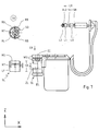
- FIG. 7 Another advantageous embodiment, which in FIG. 7 in the open and FIG. 8 in the closed state and FIG. 9 in section through FIG. 8 provides an additional opening ZL on the side of the base body Attach GL. That of the insertion opening EE in the insertion direction ER opposite end of the base body GL is firmly closed.
- a holding body SL has a through the side opening ZL in the receptacle AL of Basic body GL insertable holding part, for. B. in the form of a disc RS and a guide part LF partially encompassing the base body.
- the plug-in head is in principle similar to the example from FIGS. 1 to 4 and has in particular after the predetermined breaking point SB in the longitudinal direction LR substantially cylindrical inlet section LO, a first constriction VL1, a first head section L1, a second constriction VL2 and a second Head section L2 with a tip at its free end.
- the holding body SL which in side view and in fig. 7A in view from the z direction is shown, has a central opening SO in the disk RS, which is narrowed by several locking tongues RL.
- the central opening is in alignment with the z-direction Insertion opening and the second head portion L2 of the insertion head EL inserted through the central opening SO so that the locking tongues RL engage in the second constriction VL2 of the plug-in head and the plug-in head connect to the holding body and in particular their movement in the z direction couple.
- the disk RS is in one piece with the guide body connected and forms a closed ring around the central opening SO.
- the guide body LF has a substantially cylindrical shape and has a cross-section in the x-y plane of a ring open on one side over an angle of more than 180 °, in particular more than 240 ° around the central Opening SO on.
- the guide body is opposite the ring opening RO over an angle of advantageously at least 90 °, in particular connected approximately 180 ° to the washer RS and thus braced against bending.
- the free ring segments protruding beyond this connection area RB can be used to insert the holding body SL in the receptacle AL
- Base body GL can be bent up elastically. With the holding body inserted the inner surface of the guide body is close to the outer surface of the base body GL on and covers the additional opening ZL of the base body.
- the additional opening ZL of the base body advantageously extends over approx. 180 ° around the central longitudinal axis of the base body.
- the height HL of the additional opening ZL in the z direction is dimensioned such that a movement of the plug-in head EL in the receptacle AL together with the holding body SL within the one by the slats LA and the Stop of the locking section RA on the edge of the insertion opening EE on the other hand limited displacement by the inside of the guide body located elements of the holding body is not hindered.
- the disk RS is inside the guide body LF as well as below these stiffening webs running along the inner wall RT with a total height HE of webs RT and disc RS.
- the height HR of the guide body LF is dimensioned so that in every permissible position of the holding body SL reliably covered the additional opening ZL in the z direction is.
- the length of the cylindrical leading the holding body in the z direction The outer surface of the base body is dimensioned so that the limited movement in the z direction of the insertion head in the receptacle is disabled.
- the ring opening RO advantageously also enables the arrangement of a stabilizing web PS facing away from the receptacle ZL in the z direction Outer surface of the body. In all embodiments are on the outer surface of the base body at positions in the z direction at which Manipulations are preferably applied, revolving beads WU for reinforcement the wall thickness provided.
Landscapes
- Engineering & Computer Science (AREA)
- Computer Security & Cryptography (AREA)
- Physics & Mathematics (AREA)
- General Physics & Mathematics (AREA)
- Theoretical Computer Science (AREA)
- Connector Housings Or Holding Contact Members (AREA)
- Closures For Containers (AREA)
- Sealing Material Composition (AREA)
- Bag Frames (AREA)
- External Artificial Organs (AREA)
Abstract
Description
- Fig. 1
- eine erste Plombenanordnung in Schrägansicht,
- Fig. 2
- Plombenanordnung nach Fig. 1 in Seitenansicht,
- Fig. 3
- die Plombenanordnung nach Fig. 2 geschlossen,
- Fig. 4
- einen Schnitt entlang A-A von Fig. 3,
- Fig. 5
- eine andere vorteilhafte Ausführungsform geöffnet,
- Fig. 6
- einen Schnitt durch die Ausführungsform nach Fig. 5 geschlossen,
- Fig. 7
- eine Ausführungsform mit seitlich eingeführtem Signalstopfen geöffnet,
- Fig. 8
- die Ausführungsform nach Fig. 7 geschlossen,
- Fig. 9
- einen Schnitt durch Fig. 8.
Claims (22)
- Plombenanordnung mitdadurch gekennzeichnet, dass das Verbindungsglied am Übergang vom Riegelabschnitt zu dem Anschlagsglied eine erste Querschnittsverengung in Form eines ersten Steges aufweist und in Verlängerung des Stegs auf der diesem abgewandten Seite des Anschlagsglieds ein Freiraum vorliegt.einem Grundkörper, in welchem eine Aufnahme mit einer Verriegelung ausgebildet ist,einem Einsteckkopf, welcher durch eine Einstecköffnung in einer Einsteckrichtung in die Aufnahme einsteckbar und in eingestecktem Zustand durch die Verriegelung gegen Ausziehen gehalten ist,einem flexiblen Verbindungsglied zwischen Grundkörper und Einsteckkopf mit einem auf Seiten der Einsteckkopfes liegenden länglichen Riegelabschnitt, welcher dem Einsteckkopf abgewandt durch ein Anschlagsglied begrenzt ist,
- Anordnung nach Anspruch 1, dadurch gekennzeichnet, dass die Dicke des Anschlagsglieds in Verlängerung des ersten Stegs geringer ist als 2 mm, insbesondere geringer als 1,5 mm.
- Anordnung nach Anspruch 1 oder Anspruch 2, dadurch gekennzeichnet, dass die Dicke des Anschlagsglieds in Verlängerung des ersten Stegs klein ist gegen die kleinste Querausdehnung des Anschlagsglieds und insbesondere weniger als 30 % dieser kleinsten Querausdehnung beträgt.
- Anordnung nach einem der Ansprüche 1 bis 3, dadurch gekennzeichnet, dass auf der dem ersten Steg abgewandten Seite des Anschlagsglieds das weiterführende Verbindungsglied das Anschlagsglied in einem Bogen überbrückt, welcher in Verlängerung des ersten Stegs unmittelbar hinter dem Anschlagsglied eine Freisparung aufweist.
- Anordnung nach einem der Ansprüche 1 bis 4, dadurch gekennzeichnet, dass das Anschlagsglied scheibenförmig ausgebildet ist.
- Anordnung nach einem der Ansprüche 1 bis 5, dadurch gekennzeichnet, dass der erste Steg allseitig einen Einzug gegen das Anschlagsglied aufweist.
- Anordnung nach Anspruch 6, dadurch gekennzeichnet, dass das Maß des Einzugs größer ist als der Halbmesser des ersten Stegs in gleicher Richtung.
- Anordnung nach einem der Ansprüche 1 bis 7, dadurch gekennzeichnet, dass der erste Steg im wesentlichen zylindrisch ist.
- Anordnung nach einem der Ansprüche 1 bis 8, dadurch gekennzeichnet, dass am Übergang des Riegelabschnitts zum Einsteckkopf eine zweite Querschnittsverengung als Sollbruchstelle angeordnet ist.
- Anordnung nach Anspruch 9, dadurch gekennzeichnet, dass die Querschnittsfläche der zweiten Querschnittsverengung um wenigstens 20 % geringer ist las die Querschnittsfläche der ersten Querschnittsverengung.
- Plombenanordnung mitdadurch gekennzeichnet, dass der Haltekörper bei in diesem gehaltenem Einsteckkopf innerhalb des Grundkörpers in Längsrichtung über einen begrenzten Verschiebeweg zusammen mit dem Einsteckkopf verschiebbar ist und die Verschiebung sowohl auf Seiten der Einstecköffnung an dem Verbindungsglied als auch auf Seiten der Endöffnung an dem Haltekörper für den Benutzer erkennbar ist.einem Grundkörper mit einer Einstecköffnung und einer zusätzlichen Öffnung und einer Aufnahme zwischen den beiden Öffnungen,einem über ein Verbindungsglied mit dem Grundkörper verbundenen Einsteckkopf, welcher durch die Einstecköffnung in die Aufnahme einsteckbar ist,einen in die zusätzliche Öffnung eingesetzten und diese verschließenden Haltekörper, in welchem der eingesteckte Einsteckkopf gehalten gehalten ist,
- Anordnung nach Anspruch 11, dadurch gekennzeichnet, dass der Haltekörper ausfallgesichert in dem Grundkörper vormontiert ist.
- Anordnung nach Anspruch 11 oder 12, dadurch gekennzeichnet, dass der Einsteckkopf durch eine Verriegelung im Grundkörper gegen Ausziehen aus diesem entgegen der Einsteckrichtung gesperrt ist.
- Anordnung nach einem der Ansprüche 11 bis 13, dadurch gekennzeichnet, dass die Verschiebung des Einsteckkopfes in Einsteckrichtung begrenzt ist durch den Anschlag einer Stufe des Verbindungsglieds am Grundkörper.
- Anordnung nach Anspruch 14, dadurch gekennzeichnet, dass zwischen Einsteckkopf und Stufe des Verbindungsglieds eine Sollbruchstelle ausgebildet ist.
- Anordnung nach einem der Ansprüche 11 bis 15, dadurch gekennzeichnet, dass die zusätzliche Öffnung in Einsteckrichtung der Einstecköffnung entgegengesetzt im Grundkörper angeordnet ist.
- Anordnung nach Anspruch 16, dadurch gekennzeichnet, dass der Haltekörper eine die Spitze des Einsteckkopfes hintergreifende Klammer als eine weitere Verriegelung aufweist.
- Anordnung nach Anspruch 16, dadurch gekennzeichnet, dass der Einsteckkopf dem Haltekörper zugewandt als eine Halteklammer ausgeführt ist, welche als eine weitere Verriegelung eine Spitze des Haltekörpers hintergreift.
- Anordnung nach einem der Ansprüche 11 bis 15, dadurch gekennzeichnet, dass die zusätzliche Öffnung seitlich quer zur Einsteckrichtung im Grundkörper angeordnet ist.
- Anordnung nach Anspruch 19, dadurch gekennzeichnet, dass der Haltekörper mit einem äußeren Klammerabschnitt den Grundkörper lose umgreift.
- Anordnung nach Anspruch 19 oder 20, dadurch gekennzeichnet, dass ein Verriegelungsabschnitt des Haltekörpers in der Aufnahme eine weitere Verriegelung mit dem Einsteckkopf bildet.
- Anordnung nach Anspruch 21, dadurch gekennzeichnet, dass der Verriegelungsabschnitt einen Ring um eine zentrale Öffnung bildet und mehrere, die Spitze des Einsteckkopfes hintergreifende Sperrzungen aufweist.
Applications Claiming Priority (2)
| Application Number | Priority Date | Filing Date | Title |
|---|---|---|---|
| DE10314940 | 2003-04-02 | ||
| DE10314940.6A DE10314940B4 (de) | 2003-04-02 | 2003-04-02 | Plombenanordnung |
Publications (3)
| Publication Number | Publication Date |
|---|---|
| EP1465137A2 true EP1465137A2 (de) | 2004-10-06 |
| EP1465137A3 EP1465137A3 (de) | 2006-09-13 |
| EP1465137B1 EP1465137B1 (de) | 2010-12-22 |
Family
ID=32842217
Family Applications (1)
| Application Number | Title | Priority Date | Filing Date |
|---|---|---|---|
| EP04003577A Expired - Lifetime EP1465137B1 (de) | 2003-04-02 | 2004-02-18 | Plombenanordnung |
Country Status (3)
| Country | Link |
|---|---|
| EP (1) | EP1465137B1 (de) |
| AT (1) | ATE492870T1 (de) |
| DE (2) | DE10314940B4 (de) |
Cited By (1)
| Publication number | Priority date | Publication date | Assignee | Title |
|---|---|---|---|---|
| US20250006084A1 (en) * | 2023-06-30 | 2025-01-02 | J.J. Keller & Associates, Inc. | Security Seal |
Families Citing this family (2)
| Publication number | Priority date | Publication date | Assignee | Title |
|---|---|---|---|---|
| EP1811483A1 (de) | 2006-01-19 | 2007-07-25 | Bednorz GmbH & Co. KG | Verschlussplombe sowie Verfahren zu deren Herstellung |
| WO2015156996A1 (en) | 2014-04-11 | 2015-10-15 | E.J. Brooks Company | Thermoplastic security seal with covered locking recess |
Family Cites Families (11)
| Publication number | Priority date | Publication date | Assignee | Title |
|---|---|---|---|---|
| AT343532B (de) * | 1976-05-12 | 1978-06-12 | Withalm Hanns | Kunststoffplombe |
| US4106801A (en) * | 1975-04-01 | 1978-08-15 | Lima Castro Netto E De | One piece security seal and new sealing system |
| CH612599A5 (en) * | 1977-06-15 | 1979-08-15 | Georges Chatellier | Spray gun for an air-liquid mixture |
| FR2397692A1 (fr) * | 1977-07-13 | 1979-02-09 | Rossignot Paul Louis | Goupille de securite ou garantie |
| US4506921A (en) * | 1982-12-27 | 1985-03-26 | E. J. Brooks Company | Security seal |
| CA1225514A (en) * | 1983-08-24 | 1987-08-18 | Entreprises Tritton Ltee. (Les) | Plastic seal |
| DE9200110U1 (de) * | 1992-01-07 | 1992-03-26 | Czewo Plast Kunststofftechnik Gmbh, 93073 Neutraubling | Plombenvorrichtung |
| DE9208782U1 (de) * | 1992-07-01 | 1993-11-04 | Wodziwoda, Günter, 58507 Lüdenscheid | Sicherheitsplombe |
| GB2295797B (en) * | 1994-12-10 | 1998-03-04 | Bowthorpe Plc | Security tie |
| AU1521597A (en) * | 1996-01-25 | 1997-08-20 | E.J. Brooks Company | Security seal |
| DE19959229A1 (de) * | 1999-12-08 | 2001-06-13 | Rudolf Held Gmbh & Co Kg Metal | Sicherungsplombe |
-
2003
- 2003-04-02 DE DE10314940.6A patent/DE10314940B4/de not_active Expired - Fee Related
-
2004
- 2004-02-18 DE DE502004012014T patent/DE502004012014D1/de not_active Expired - Lifetime
- 2004-02-18 EP EP04003577A patent/EP1465137B1/de not_active Expired - Lifetime
- 2004-02-18 AT AT04003577T patent/ATE492870T1/de active
Cited By (2)
| Publication number | Priority date | Publication date | Assignee | Title |
|---|---|---|---|---|
| US20250006084A1 (en) * | 2023-06-30 | 2025-01-02 | J.J. Keller & Associates, Inc. | Security Seal |
| US12488707B2 (en) * | 2023-06-30 | 2025-12-02 | J. J. Keller & Associates, Inc. | Security seal |
Also Published As
| Publication number | Publication date |
|---|---|
| DE10314940B4 (de) | 2014-04-17 |
| DE502004012014D1 (de) | 2011-02-03 |
| EP1465137A3 (de) | 2006-09-13 |
| ATE492870T1 (de) | 2011-01-15 |
| EP1465137B1 (de) | 2010-12-22 |
| DE10314940A1 (de) | 2004-10-14 |
Similar Documents
| Publication | Publication Date | Title |
|---|---|---|
| DE69323423T2 (de) | Gegen manipulation gesicherter schraubverschluss | |
| DE2502663C2 (de) | Befestiger | |
| DE2432444C2 (de) | Griffringsbefestigung für einen fälschungssicheren Verschluß | |
| DE4309088C2 (de) | Ortsfest einbaubare Scheibe für Kraftfahrzeuge | |
| DE3622501C2 (de) | Rastvorrichtung zur Verriegelung | |
| EP3452734B1 (de) | Clip zum befestigen eines ersten elements an einem zweiten element | |
| EP1600190A1 (de) | Spritzenverschluss und Verfahren zum Herstellen eines Spritzenverschlusses | |
| EP2916894A1 (de) | Spritzenverschluss | |
| DE69415333T2 (de) | Gegossene sicherheitsnadel | |
| EP1769896B1 (de) | Verbindungssystem | |
| DE69828292T2 (de) | Hakenförmige vorrichtung | |
| EP0660792B1 (de) | Spritzgegossener kunststoffeimer | |
| EP2569225B1 (de) | Verschluss für ein behältnis und verfahren zur durchführung eines gefrier-trocknungsverfahrens | |
| EP1118071B1 (de) | Anhänger mit verriegelbarem bügel | |
| EP0451102B1 (de) | Verschlusskappe aus Kunststoff | |
| DE10314940B4 (de) | Plombenanordnung | |
| WO2020254367A1 (de) | Behälterverschluss | |
| EP0952282B1 (de) | Türverschluss mit Betätigung und zugehörigem Steckschlüssel | |
| DE19642045C2 (de) | Plombiereinrichtung | |
| EP4011800B1 (de) | Behälterdeckel mit verschliessbarer ventilierungsöffnung | |
| EP1522058B1 (de) | Sicherheitsverschluss | |
| EP0407803B1 (de) | Flaschenöffner | |
| EP2214976B1 (de) | Garantieschraubverschluss | |
| EP1084961B1 (de) | Verschlusseinrichtung mit einbringbarer Sicherung | |
| EP0498954A1 (de) | Verschlusskappe für Kunststoffverschluss |
Legal Events
| Date | Code | Title | Description |
|---|---|---|---|
| PUAI | Public reference made under article 153(3) epc to a published international application that has entered the european phase |
Free format text: ORIGINAL CODE: 0009012 |
|
| AK | Designated contracting states |
Kind code of ref document: A2 Designated state(s): AT BE BG CH CY CZ DE DK EE ES FI FR GB GR HU IE IT LI LU MC NL PT RO SE SI SK TR |
|
| AX | Request for extension of the european patent |
Extension state: AL LT LV MK |
|
| PUAL | Search report despatched |
Free format text: ORIGINAL CODE: 0009013 |
|
| AK | Designated contracting states |
Kind code of ref document: A3 Designated state(s): AT BE BG CH CY CZ DE DK EE ES FI FR GB GR HU IE IT LI LU MC NL PT RO SE SI SK TR |
|
| AX | Request for extension of the european patent |
Extension state: AL LT LV MK |
|
| 17P | Request for examination filed |
Effective date: 20061025 |
|
| AKX | Designation fees paid |
Designated state(s): AT BE BG CH CY CZ DE DK EE ES FI FR GB GR HU IE IT LI LU MC NL PT RO SE SI SK TR |
|
| GRAP | Despatch of communication of intention to grant a patent |
Free format text: ORIGINAL CODE: EPIDOSNIGR1 |
|
| GRAS | Grant fee paid |
Free format text: ORIGINAL CODE: EPIDOSNIGR3 |
|
| GRAA | (expected) grant |
Free format text: ORIGINAL CODE: 0009210 |
|
| AK | Designated contracting states |
Kind code of ref document: B1 Designated state(s): AT BE BG CH CY CZ DE DK EE ES FI FR GB GR HU IE IT LI LU MC NL PT RO SE SI SK TR |
|
| REG | Reference to a national code |
Ref country code: GB Ref legal event code: FG4D Free format text: NOT ENGLISH |
|
| REG | Reference to a national code |
Ref country code: CH Ref legal event code: EP |
|
| REG | Reference to a national code |
Ref country code: IE Ref legal event code: FG4D |
|
| REF | Corresponds to: |
Ref document number: 502004012014 Country of ref document: DE Date of ref document: 20110203 Kind code of ref document: P |
|
| REG | Reference to a national code |
Ref country code: DE Ref legal event code: R096 Ref document number: 502004012014 Country of ref document: DE Effective date: 20110203 |
|
| REG | Reference to a national code |
Ref country code: NL Ref legal event code: VDEP Effective date: 20101222 |
|
| PG25 | Lapsed in a contracting state [announced via postgrant information from national office to epo] |
Ref country code: SE Free format text: LAPSE BECAUSE OF FAILURE TO SUBMIT A TRANSLATION OF THE DESCRIPTION OR TO PAY THE FEE WITHIN THE PRESCRIBED TIME-LIMIT Effective date: 20101222 Ref country code: BG Free format text: LAPSE BECAUSE OF FAILURE TO SUBMIT A TRANSLATION OF THE DESCRIPTION OR TO PAY THE FEE WITHIN THE PRESCRIBED TIME-LIMIT Effective date: 20110322 Ref country code: CY Free format text: LAPSE BECAUSE OF FAILURE TO SUBMIT A TRANSLATION OF THE DESCRIPTION OR TO PAY THE FEE WITHIN THE PRESCRIBED TIME-LIMIT Effective date: 20101222 Ref country code: SI Free format text: LAPSE BECAUSE OF FAILURE TO SUBMIT A TRANSLATION OF THE DESCRIPTION OR TO PAY THE FEE WITHIN THE PRESCRIBED TIME-LIMIT Effective date: 20101222 Ref country code: FI Free format text: LAPSE BECAUSE OF FAILURE TO SUBMIT A TRANSLATION OF THE DESCRIPTION OR TO PAY THE FEE WITHIN THE PRESCRIBED TIME-LIMIT Effective date: 20101222 |
|
| REG | Reference to a national code |
Ref country code: IE Ref legal event code: FD4D |
|
| PG25 | Lapsed in a contracting state [announced via postgrant information from national office to epo] |
Ref country code: CZ Free format text: LAPSE BECAUSE OF FAILURE TO SUBMIT A TRANSLATION OF THE DESCRIPTION OR TO PAY THE FEE WITHIN THE PRESCRIBED TIME-LIMIT Effective date: 20101222 Ref country code: PT Free format text: LAPSE BECAUSE OF FAILURE TO SUBMIT A TRANSLATION OF THE DESCRIPTION OR TO PAY THE FEE WITHIN THE PRESCRIBED TIME-LIMIT Effective date: 20110422 Ref country code: EE Free format text: LAPSE BECAUSE OF FAILURE TO SUBMIT A TRANSLATION OF THE DESCRIPTION OR TO PAY THE FEE WITHIN THE PRESCRIBED TIME-LIMIT Effective date: 20101222 Ref country code: ES Free format text: LAPSE BECAUSE OF FAILURE TO SUBMIT A TRANSLATION OF THE DESCRIPTION OR TO PAY THE FEE WITHIN THE PRESCRIBED TIME-LIMIT Effective date: 20110402 Ref country code: GR Free format text: LAPSE BECAUSE OF FAILURE TO SUBMIT A TRANSLATION OF THE DESCRIPTION OR TO PAY THE FEE WITHIN THE PRESCRIBED TIME-LIMIT Effective date: 20110323 |
|
| BERE | Be: lapsed |
Owner name: RUDOLF HELD G.M.B.H. & CO. KG Effective date: 20110228 |
|
| PG25 | Lapsed in a contracting state [announced via postgrant information from national office to epo] |
Ref country code: SK Free format text: LAPSE BECAUSE OF FAILURE TO SUBMIT A TRANSLATION OF THE DESCRIPTION OR TO PAY THE FEE WITHIN THE PRESCRIBED TIME-LIMIT Effective date: 20101222 Ref country code: NL Free format text: LAPSE BECAUSE OF FAILURE TO SUBMIT A TRANSLATION OF THE DESCRIPTION OR TO PAY THE FEE WITHIN THE PRESCRIBED TIME-LIMIT Effective date: 20101222 Ref country code: RO Free format text: LAPSE BECAUSE OF FAILURE TO SUBMIT A TRANSLATION OF THE DESCRIPTION OR TO PAY THE FEE WITHIN THE PRESCRIBED TIME-LIMIT Effective date: 20101222 |
|
| PG25 | Lapsed in a contracting state [announced via postgrant information from national office to epo] |
Ref country code: MC Free format text: LAPSE BECAUSE OF NON-PAYMENT OF DUE FEES Effective date: 20110228 |
|
| REG | Reference to a national code |
Ref country code: CH Ref legal event code: PL |
|
| PLBE | No opposition filed within time limit |
Free format text: ORIGINAL CODE: 0009261 |
|
| STAA | Information on the status of an ep patent application or granted ep patent |
Free format text: STATUS: NO OPPOSITION FILED WITHIN TIME LIMIT |
|
| PG25 | Lapsed in a contracting state [announced via postgrant information from national office to epo] |
Ref country code: IE Free format text: LAPSE BECAUSE OF FAILURE TO SUBMIT A TRANSLATION OF THE DESCRIPTION OR TO PAY THE FEE WITHIN THE PRESCRIBED TIME-LIMIT Effective date: 20101222 Ref country code: DK Free format text: LAPSE BECAUSE OF FAILURE TO SUBMIT A TRANSLATION OF THE DESCRIPTION OR TO PAY THE FEE WITHIN THE PRESCRIBED TIME-LIMIT Effective date: 20101222 Ref country code: CH Free format text: LAPSE BECAUSE OF NON-PAYMENT OF DUE FEES Effective date: 20110228 Ref country code: LI Free format text: LAPSE BECAUSE OF NON-PAYMENT OF DUE FEES Effective date: 20110228 |
|
| 26N | No opposition filed |
Effective date: 20110923 |
|
| PG25 | Lapsed in a contracting state [announced via postgrant information from national office to epo] |
Ref country code: BE Free format text: LAPSE BECAUSE OF NON-PAYMENT OF DUE FEES Effective date: 20110228 |
|
| PG25 | Lapsed in a contracting state [announced via postgrant information from national office to epo] |
Ref country code: IT Free format text: LAPSE BECAUSE OF FAILURE TO SUBMIT A TRANSLATION OF THE DESCRIPTION OR TO PAY THE FEE WITHIN THE PRESCRIBED TIME-LIMIT Effective date: 20101222 |
|
| REG | Reference to a national code |
Ref country code: DE Ref legal event code: R097 Ref document number: 502004012014 Country of ref document: DE Effective date: 20110923 |
|
| REG | Reference to a national code |
Ref country code: AT Ref legal event code: MM01 Ref document number: 492870 Country of ref document: AT Kind code of ref document: T Effective date: 20110218 |
|
| PG25 | Lapsed in a contracting state [announced via postgrant information from national office to epo] |
Ref country code: AT Free format text: LAPSE BECAUSE OF NON-PAYMENT OF DUE FEES Effective date: 20110218 |
|
| PG25 | Lapsed in a contracting state [announced via postgrant information from national office to epo] |
Ref country code: LU Free format text: LAPSE BECAUSE OF NON-PAYMENT OF DUE FEES Effective date: 20110218 |
|
| PG25 | Lapsed in a contracting state [announced via postgrant information from national office to epo] |
Ref country code: TR Free format text: LAPSE BECAUSE OF FAILURE TO SUBMIT A TRANSLATION OF THE DESCRIPTION OR TO PAY THE FEE WITHIN THE PRESCRIBED TIME-LIMIT Effective date: 20101222 |
|
| PG25 | Lapsed in a contracting state [announced via postgrant information from national office to epo] |
Ref country code: HU Free format text: LAPSE BECAUSE OF FAILURE TO SUBMIT A TRANSLATION OF THE DESCRIPTION OR TO PAY THE FEE WITHIN THE PRESCRIBED TIME-LIMIT Effective date: 20101222 |
|
| REG | Reference to a national code |
Ref country code: DE Ref legal event code: R082 Ref document number: 502004012014 Country of ref document: DE Representative=s name: BAUR & WEBER PATENTANWAELTE, DE Ref country code: DE Ref legal event code: R082 Ref document number: 502004012014 Country of ref document: DE Representative=s name: BAUR & WEBER PATENTANWAELTE PARTG MBB, DE |
|
| REG | Reference to a national code |
Ref country code: FR Ref legal event code: PLFP Year of fee payment: 12 |
|
| PGFP | Annual fee paid to national office [announced via postgrant information from national office to epo] |
Ref country code: DE Payment date: 20150228 Year of fee payment: 12 |
|
| PGFP | Annual fee paid to national office [announced via postgrant information from national office to epo] |
Ref country code: FR Payment date: 20150217 Year of fee payment: 12 Ref country code: GB Payment date: 20150223 Year of fee payment: 12 |
|
| REG | Reference to a national code |
Ref country code: DE Ref legal event code: R119 Ref document number: 502004012014 Country of ref document: DE |
|
| GBPC | Gb: european patent ceased through non-payment of renewal fee |
Effective date: 20160218 |
|
| REG | Reference to a national code |
Ref country code: FR Ref legal event code: ST Effective date: 20161028 |
|
| PG25 | Lapsed in a contracting state [announced via postgrant information from national office to epo] |
Ref country code: GB Free format text: LAPSE BECAUSE OF NON-PAYMENT OF DUE FEES Effective date: 20160218 Ref country code: FR Free format text: LAPSE BECAUSE OF NON-PAYMENT OF DUE FEES Effective date: 20160229 Ref country code: DE Free format text: LAPSE BECAUSE OF NON-PAYMENT OF DUE FEES Effective date: 20160901 |