EP1464472B1 - Schwingarmvorrichtung zur Herstellung einer Reifenverstärkungsstruktur mit einem einzigen Reifenkord - Google Patents
Schwingarmvorrichtung zur Herstellung einer Reifenverstärkungsstruktur mit einem einzigen Reifenkord Download PDFInfo
- Publication number
- EP1464472B1 EP1464472B1 EP04015938A EP04015938A EP1464472B1 EP 1464472 B1 EP1464472 B1 EP 1464472B1 EP 04015938 A EP04015938 A EP 04015938A EP 04015938 A EP04015938 A EP 04015938A EP 1464472 B1 EP1464472 B1 EP 1464472B1
- Authority
- EP
- European Patent Office
- Prior art keywords
- arm
- rotation
- centre
- transport head
- wire
- Prior art date
- Legal status (The legal status is an assumption and is not a legal conclusion. Google has not performed a legal analysis and makes no representation as to the accuracy of the status listed.)
- Expired - Lifetime
Links
- 238000004519 manufacturing process Methods 0.000 title claims description 17
- 230000003014 reinforcing effect Effects 0.000 title description 3
- 230000002787 reinforcement Effects 0.000 claims abstract description 33
- 230000033001 locomotion Effects 0.000 claims description 77
- 230000032258 transport Effects 0.000 claims description 57
- 230000010355 oscillation Effects 0.000 claims description 9
- 238000000151 deposition Methods 0.000 claims description 7
- 238000003825 pressing Methods 0.000 abstract description 10
- 230000007246 mechanism Effects 0.000 abstract description 6
- 239000011324 bead Substances 0.000 description 24
- 230000009471 action Effects 0.000 description 6
- 229920001971 elastomer Polymers 0.000 description 6
- 238000000034 method Methods 0.000 description 4
- 210000000056 organ Anatomy 0.000 description 3
- 230000008901 benefit Effects 0.000 description 2
- 230000015572 biosynthetic process Effects 0.000 description 2
- 238000005520 cutting process Methods 0.000 description 2
- 125000004122 cyclic group Chemical group 0.000 description 2
- 230000008021 deposition Effects 0.000 description 2
- 238000004026 adhesive bonding Methods 0.000 description 1
- 238000004873 anchoring Methods 0.000 description 1
- 238000012550 audit Methods 0.000 description 1
- 230000005540 biological transmission Effects 0.000 description 1
- 229920005549 butyl rubber Polymers 0.000 description 1
- 238000010073 coating (rubber) Methods 0.000 description 1
- 239000011248 coating agent Substances 0.000 description 1
- 238000000576 coating method Methods 0.000 description 1
- 230000003247 decreasing effect Effects 0.000 description 1
- 230000001419 dependent effect Effects 0.000 description 1
- 230000000694 effects Effects 0.000 description 1
- 239000012467 final product Substances 0.000 description 1
- 238000011065 in-situ storage Methods 0.000 description 1
- 238000009434 installation Methods 0.000 description 1
- 238000005304 joining Methods 0.000 description 1
- 239000000463 material Substances 0.000 description 1
- 230000009347 mechanical transmission Effects 0.000 description 1
- 239000012528 membrane Substances 0.000 description 1
- 230000007935 neutral effect Effects 0.000 description 1
- 230000010363 phase shift Effects 0.000 description 1
- 230000000717 retained effect Effects 0.000 description 1
- 239000011265 semifinished product Substances 0.000 description 1
- 125000006850 spacer group Chemical group 0.000 description 1
- 238000005728 strengthening Methods 0.000 description 1
- 230000009466 transformation Effects 0.000 description 1
- 230000001131 transforming effect Effects 0.000 description 1
- 230000001960 triggered effect Effects 0.000 description 1
- 238000011144 upstream manufacturing Methods 0.000 description 1
Images


Classifications
-
- B—PERFORMING OPERATIONS; TRANSPORTING
- B29—WORKING OF PLASTICS; WORKING OF SUBSTANCES IN A PLASTIC STATE IN GENERAL
- B29D—PRODUCING PARTICULAR ARTICLES FROM PLASTICS OR FROM SUBSTANCES IN A PLASTIC STATE
- B29D30/00—Producing pneumatic or solid tyres or parts thereof
- B29D30/06—Pneumatic tyres or parts thereof (e.g. produced by casting, moulding, compression moulding, injection moulding, centrifugal casting)
- B29D30/08—Building tyres
- B29D30/20—Building tyres by the flat-tyre method, i.e. building on cylindrical drums
- B29D30/30—Applying the layers; Guiding or stretching the layers during application
-
- B—PERFORMING OPERATIONS; TRANSPORTING
- B29—WORKING OF PLASTICS; WORKING OF SUBSTANCES IN A PLASTIC STATE IN GENERAL
- B29D—PRODUCING PARTICULAR ARTICLES FROM PLASTICS OR FROM SUBSTANCES IN A PLASTIC STATE
- B29D30/00—Producing pneumatic or solid tyres or parts thereof
- B29D30/06—Pneumatic tyres or parts thereof (e.g. produced by casting, moulding, compression moulding, injection moulding, centrifugal casting)
- B29D30/08—Building tyres
- B29D30/10—Building tyres on round cores, i.e. the shape of the core is approximately identical with the shape of the completed tyre
- B29D30/16—Applying the layers; Guiding or stretching the layers during application
- B29D30/1635—Applying the layers; Guiding or stretching the layers during application by feeding a continuous band and moving it back and forth (zig-zag) to form an annular element
-
- B—PERFORMING OPERATIONS; TRANSPORTING
- B29—WORKING OF PLASTICS; WORKING OF SUBSTANCES IN A PLASTIC STATE IN GENERAL
- B29D—PRODUCING PARTICULAR ARTICLES FROM PLASTICS OR FROM SUBSTANCES IN A PLASTIC STATE
- B29D30/00—Producing pneumatic or solid tyres or parts thereof
- B29D30/06—Pneumatic tyres or parts thereof (e.g. produced by casting, moulding, compression moulding, injection moulding, centrifugal casting)
- B29D30/08—Building tyres
- B29D30/10—Building tyres on round cores, i.e. the shape of the core is approximately identical with the shape of the completed tyre
- B29D30/16—Applying the layers; Guiding or stretching the layers during application
- B29D2030/1664—Details, accessories or auxiliary operations not provided for in the other subgroups of B29D30/00
- B29D2030/1678—Details, accessories or auxiliary operations not provided for in the other subgroups of B29D30/00 the layers being applied being substantially continuous, i.e. not being cut before the application step
Definitions
- the present invention relates to the manufacture of tires. More specifically, it relates to the establishment of son to provide a strengthening of the tire. More particularly, it proposes means capable of manufacturing such a reinforcement on a near or identical shape of the shape of the internal cavity of the tire, that is to say a substantially toroidal shape, supporting the tire blank during its manufacture.
- It shows an apparatus in which the wire, intended to constitute a carcass reinforcement, is placed in adjacent arches on a rigid core, by an eyelet fixed on a chain mounted on pulleys so as to surround the core forming a kind of 'forking.
- the eyelet moves back and forth around the core so as to posit, progressively and contiguously, a hoop each way and a hoop on each return, with the intervention of appropriate pressers to apply the ends of said hoops to the hoop. as on the rigid core, pre-coated with raw rubber.
- the object of the present invention is to provide alternative equipment for laying a reinforcing wire on a core substantially in the same way.
- the pressers essentially comprise each a fork and a hammer.
- the embodiment of the pressors described therein could be taken as is, although it is proposed below a new form for said pressers.
- the invention provides the main differences.
- the swingarm system (s) described below are designed to be able to take the place of the chain system described in the aforementioned patent.
- the term "wire” must of course be understood in a very general sense, including a monofilament, a multifilament, an assembly such as a cable or a twist, or a small number of cables or twisted bundles, and this regardless of the nature of the material, and that the "wire” is pre-coated with rubber or not.
- the term “hoop” is used to refer to a stretch of wire from one point singular to another in the reinforcement frame. All these hoops arranged around the entire periphery of the tire forms the reinforcement itself.
- a hoop in the sense defined herein may be part of a carcass, or a vertex reinforcement, or any other type of reinforcement. These arches can be individualized by cutting the wire during laying, or all interconnected in the final reinforcement, for example by loops.
- the invention deals with the continuous removal of a reinforcement yarn, in a configuration as close as possible to the configuration in the final product.
- the wire being delivered on demand by a suitable distributor comprising, for example, a spool of thread and, if appropriate, a device for controlling the tension of the thread extracted from the spool, the apparatus for manufacturing a reinforcement from a spool.
- a suitable distributor comprising, for example, a spool of thread and, if appropriate, a device for controlling the tension of the thread extracted from the spool, the apparatus for manufacturing a reinforcement from a spool.
- single wire cooperates with a form (rigid core or an armed membrane) on which the tire is manufactured. It matters little that the reinforcement is, to be complete, made in several successive passes of the laying members described, with wire cutting or not between two passes.
- the wire laying members described here also make it possible to carry out a reinforcement, for example a carcass reinforcement, in which the pitch of the wire is variable.
- the term "no laying" the distance resulting from the sum of the gap between two adjacent son and the diameter of the wire. It is well known that for a carcass reinforcement, the spacing between wires varies according to the radius at which it is measured. It is not a question of this variation of which we are speaking here, but of a variable step at a given radius. It suffices for this, without changing the working rate of the guide member, to vary in any appropriate law the speed of rotation of the form. This produces a tire whose carcass reinforcement son, for example for a radial carcass, are arranged in a pitch having a controlled variation for a given radial position.
- the first embodiment uses a cascade of three functional swing arms.
- a cascade with three functional oscillating arms is preferably used for the removal of carcass hoops going from one bead to the other bead of the tire.
- the second embodiment uses a cascade of two functional swing arms.
- An embodiment variant is furthermore given for this second embodiment.
- a cascade with two functional oscillating arms for the removal of carcass hoops going from a bead to a shoulder of the tire will be used.
- the third embodiment uses a single functional oscillating arm, which is sufficient for the simplest depositions to achieve.
- n th arm the functional oscillating arm on which the wire guiding member is directly fixed, the arm of base still being the oscillating "first arm”.
- the oscillating arms are arranged in cascade so that, in general, the transport head of the swing arm "p" (with p ⁇ n) carries the center of rotation of the swing arm "p + 1". This is why it was stated above that the transport head carries the guide member of the wire directly, or only “indirectly” (ie via one or more other oscillating arms functional).
- the geometric axis of the center of rotation of the first oscillating arm is, in the working position, entirely outside the shape that it never meets, ie not even by its extensions. .
- the apparatus causes the yarn guiding member to move substantially in a plane - the plane of motion - perpendicular to the geometric axis of rotation of the base arm.
- the base arm or according to the variants each of the oscillating arms used is planar, elongate, and the base arm oscillates in this plane of movement, or the all oscillating arms move in parallel and neighboring planes, one of them being very close to this plane of movement, or even be confused with this plane of movement, depending on the nature of the guiding member used.
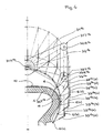
- the shape is a core 1 (rigid and removable) defining the geometry of the inner surface of the tire.
- This one is coated with rubber 10 (see figure 7 ), for example a layer of rubber butyl rubber gum, and a layer of gum ensuring the coating of the carcass son.
- the rubber 10 covering the core 1 allows to retain a wire 4 on the core 1 as it is removed, by a gluing effect.
- the core 1 is rotated by any suitable device, not shown.
- the actual laying members essentially comprise a rocker arm system 3 1a on the one hand, and presser devices 2 G and 2 D the other.
- the convention used is to designate similar members by the same main reference, for example "3" for the swingarm system, and to mark the specific membership of an embodiment or a variant by a number placed in superscript, for example " 1a " for the first embodiment (using a cascade of three oscillating arms), in its variant "a”.
- a reference without a specific mark refers to an organ that is always the same in the different variants or must be understood as denoting all the variants of all the embodiments.
- the oscillating arm system 3 1a comprises three functional oscillating arms 31 1a, 32 1a, 33 1a arranged in cascade and an auxiliary arm 34 1a.
- This arrangement with three functional oscillating arms makes it easy to move the guide member from one bead to the other, and thus to obtain, in conjunction with the pressing devices 2 and G 2 D, an action of the apparatus one bead to another.
- An eyelet 6 constitutes in all the examples described here the materialization of the guide member of the wire 4 (without this being limiting). The eyecup is always mounted on the last swingarm.
- the swingarm system 3 fulfills the function performed by the chain system in the application for EP 0 580 055 supra, and the pressing devices 2 G 2 and D are appropriately positioned to act as described in the application of EP 0 580 055 supra.
- the oscillating arm system 31a is mounted on a plate 30a , and is described to the eyepiece 6a a movement flying over the core 1, and even bypassing it in many embodiments.
- the oscillating arm system 3 makes the eyecup 6 move in a plane.
- the eyecup 6 is flared: it forms a funnel with a large opening 61 on the side of the arrival of the wire 4, and a smaller orifice 62 on the output side of the wire 4 (see also FIG. figure 3 ). It is the small orifice 62 which describes a movement in said plane of movement of the guide member.
- the eyecup can be oriented so as to approximate the average orientation of the wire at the exit of the eyecup.
- the plate 30 1a comprises a 3D oscillating shaft 1a (see also 3D to Figures 10 and 11 ) Motorizing the trailing arm system, the geometric axis of said oscillating shaft 3D 1a being located radially outside the core 1. In other words, the geometric axis of said oscillating shaft 3D 1a is situated beyond the core surface 1 , without its extension meeting the core 1. Said 3D oscillating shaft 1a does not perform a continuous rotation, but oscillates within the limits of an arc less than 360 °, the precise value depending on the exact constitution of the arm system oscillating 3 and the intended application.
- the entire swingarm system 3 itself is quite compact. All the installation members, namely the oscillating arm system 3 and the pressing devices 2, including the motor and the drive mechanism, form a subset that can easily be presented to the core appropriately, and can be retracted for example to present to the core of other devices used for the manufacture of a tire or for the evacuation of the core to other tire manufacturing stations.
- a base arm (or first arm) 31 1a ( figure 1 ) is mounted on the 3D oscillating shaft 1a by a center of rotation 31R 1a .
- the first arm 31 1a comprises a transport head 31T 1a at the end opposite the center of rotation 31R 1a .
- a second arm 32 1a articulated by a center of rotation 32R 1a of the second arm, is mounted on the transport head 31T 1a of the first arm 31 1a .
- This second arm 32 1a comprises a transport head 32T 1a .
- a parallelogram is formed by means of an auxiliary arm 34 1a , mounted oscillating about on an oscillating shaft 34D 1a by its center of rotation 34R 1a .
- the center of rotation 34R 1a is located radially outside the surface of the core 1, and radially between the latter and the center of rotation 31R 1a of the first arm 31 1a .
- the auxiliary arm 34 1a comprises a transport head 34T 1a articulated on the second arm 32 1a which comprises for this purpose an intermediate center of rotation 32I 1a located between the center of rotation 32R 1a and the transport head 32T 1a of said second arm 32 1a .
- the singular points that are the centers of rotation 31R 1a , 34R 1a and transport heads 31T 1a , 34T 1a form a parallelogram.
- these points are exactly aligned with the passage of the median position in the median plane, defined by the axis MM joining the centers of rotation 31R 1a , 34R 1a and the geometric axis of the 3D shaft (as well as by the geometric axis of the shaft 34D 1a which is of course parallel to the previous).
- the eyepiece 6 describes a movement whose path is symmetrical with respect to this median plane, and it reaches the vicinity of each of the bead zones defined on the core 1, in a perfectly symmetrical movement, even in its control. .
- the apparatus comprises a third arm 33 1a , articulated by its center of rotation 33R 1a on the transport head 32T 1a of the second arm 32 1a .
- This third arm 33 1a comprises a transport head LP 1a , on which is mounted directly the eyecup 6.
- the control means of the relative position of the third arm 33 1a relative to the second arm 32 1a not shown in figure 1 not to overload the drawing.
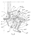
- a motor 35 controls the movement of all the arms 31 1a, 32 1a, 33 1a, 34 1a, preferably by motorization of the two shafts 1a and 3D 34D 1a, as explained in detail by means of Figures 10 and 11 .
- the motor 1a rotates a plate 70.
- An axis 71 is embedded in the plate 70 in a predetermined eccentric position.
- the shaft 71 supports a roller 72.
- a carriage 73 is translated on slides 74 arranged on the housing of the plate 30 1a .
- the carriage 73 comprises a rectilinear light 75, oriented perpendicularly to the direction of translation of the carriage 73 on the slideways 74.
- a chain (with tensioner) 76 is mounted on two identical pinions 77, and connected at its ends to the carriage 73.
- the pinions identical 77 are fixed one on the 3D shaft and the other on the shaft 34D.
- the roller 72 performs a circular motion 70R at a constant speed. In doing so, the roller 72 ascends and descends into the light 75, and translates the carriage 73, thus transforming a constant speed rotational movement into reciprocating and linear motion, the speed of which varies sinusoidally.
- this alternating linear motion is transformed on the 3D and 34D shafts, in oscillation scanning an arc less than 360 °.
- the amplitude of the oscillation can be adjusted by adjusting the radius at which the axis 71, therefore the roller 72) is mounted eccentrically on the plate 70.
- a wire 4 is delivered by a coil (not shown) and is then threaded onto a feed device 5 1a to bring and present the wire 4 correctly to the laying members.
- the feed device 5a comprises means ensuring the control of the tension of the thread 4, and if necessary the necessary compensation between the delivery members 31a and the spool, because the thread is called by said setting members at a cyclically variable speed, which can even be negative.
- the wire 4 is threaded into a first ring 51 1a disposed at some distance from the plane of movement, in which the eyelet 6 performs its cyclic movement.
- the ring 51 1a is disposed centrally with respect to the core 1.
- the wire 4 is then threaded into a ring 52 attached to the second arm 32 1a .
- the presser 2 D which comprises a fork 21 D and a hammer 22 D , both movable between a retracted position, in R (position away from the core 1), and an advanced position, in A. sees in ghost sight the hammer in advanced position.
- the convention used is to designate each member of the pressers by a main reference, for example "21" for the fork, and to mark the specific membership of the presser on one side, the side left or the right side at the figure 1 , respectively by the letter “ G " or " D " placed in superscript.
- a reference without a specific mark generically refers to one or the other of the pressers or to their organs.
- both the fork 21 and the hammer 22 have the appearance of parallel blades.
- the fork 21 is, relative to the hammer, always arranged radially on the side of the axis of rotation of the core 1.
- the fork 21 has a head 210 in "V", to take and center the wire 4. During the phase the plane formed by the "V” is arranged perpendicular to the wire 4.
- the blade forming the fork 21 is oriented tangentially to a circle concentric with the core 1.
- the fork 21 also includes an obvious 211 whose role will appear below.
- the fork 21 is intended to carry the wire 4 against the core 1.
- its advance towards the core 1 is triggered when the eyecup 6 has brought the wire 4 to one end of the movement in va-and- comes, ie when the device is substantially in the configuration of the figure 4 .
- the fork 21 is stopped when it anchored the thread in the rubber coating the core 1. Said fork 21 therefore allows to press the wire 4 with sufficient force to adhere properly to the desired location.
- the continued movement of the oscillating arm system 3 causes the formation of a loop around the tip 212, which initiates the removal of a new arch 40 on the core 1 (see figure 1 ).
- the passage of the eyecup 6 beyond the fork 21 in the return phase is allowed by the 211 obviously, although the fork 21 is pressed against the core 1 in this phase of manufacture.
- the size of the loop is a function of the size of the tip 212.
- the hammer 22 intervenes after the fork 21 and after the so-called return phase of the eyelet 6.
- the hammer 22 presses the wire 4 to a slightly higher radial position. Preferably, it still holds the wire 4 while retracting the fork 21. Maintaining the hammer while the fork retracts helps to prevent the fork 21 from taking with it the loop of wire 4 which has formed around one of its points 212, and that even if it is glued on the rubber, could tend to remain attached to the fork.
- the anchoring of the wire 4 in the bead is perfectly reliable.
- the tilting in the advanced position, and the return to the retracted position, both for the fork 21 and for the hammer 22, are controlled in synchronism with the oscillating arm system 31a , by any suitable device (movement reversal).
- the 3D shaft by a suitable mechanical transmission, for example by belt or cable or by electrical synchronization between several motors).
- a device or an equivalent device is simply shown schematically by an arrow, and designated by the reference 2, it being understood that this refers generally to a device with two actuators such as a fork and a hammer, intervening in sequence on the wire 4.
- the arm system 3 1b further comprises three functional arms 31 1b , 32 1b , 33 1b arranged in cascade, and said control means also allow, in conjunction with pressing devices, an action of the device from one bead to another.
- a base arm (or first arm) 31 1b is mounted on a 3D oscillating shaft 1b by a center of rotation 31R 1b .
- the first arm 31 1b comprises a transport head 31T 1b at the end opposite the center of rotation 31R 1b .
- a second arm 32 1b articulated by a center of rotation 32R 1b of the second arm, is mounted on the transport head 31T 1b of the first arm 31 1b .
- This second arm 32 1b comprises a transport head 32T 1b .
- the apparatus comprises a third arm 33 1b articulated by its center of rotation 33R 1b on the transport head 32T 1b of the second arm 32 1b .
- This third arm 33 1b comprises a transport head LP 1b , on which is directly mounted the eyelet 6.
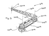
- the driving pulley 311 1b centered on the center of rotation 31R 1b of said first arm.
- the driving pulley 311 1b is integral with a flange 37 1b fixedly mounted on said platen (not shown in FIG. figure 3 ).
- a driven pulley 312 1b is integral (that is to say without possible relative rotation) of the second arm 32 1b .
- a toothed belt 361 1b connects said driving pulley and driven pulley.
- the diameters of the driving pulley and driven pulley are identical so that, during its movement, the second arm 32 1b always remains parallel to itself.
- the pulleys used are notched pulleys.
- the belts, also notched work without relative sliding relative to the pulleys on which they are mounted.
- the terms "pulley” and “belt” encompass all equivalent systems to control relative positions without slippage.
- the flange 37 1b is fixed in space, but more generally, it is important that its angular position is controlled independently of the oscillation control of said first arm. For example, it is possible to introduce a degree of freedom between the plate and the flange 37 1b , and to control the relative position of said puddle 37 1b with respect to the plate, in order to act selectively on the spatial position of the driving pulley 311 1b so as to for example, adapting the movement executed by the eyecup 6 to shapes of different sizes.
- the means for controlling the relative position of the third arm 33 1b relative to the second arm 32 1b essentially comprise a driving pulley 321 1b centered on the center of rotation 32R 1b of said second arm 32 1b , integral (no relative rotation possible) of the first arm 31 1b , and they comprise a driven pulley 322 1b integral (likewise, no possible relative rotation) of said third arm 33 1b .
- a toothed belt 362 1b connects said driving pulley and driven pulley.
- the diameters of the driving pulley and driven pulley are different, their respective values being calculated so that the transport end LP 1b , during its movement, reaches the zone of the core 1 near the bead (see figure 4 ), without the second arm 32 1b comes to hit the flank 11 of the core 1.
- the figure 4 shows the eyecup 6 in the position 6 (a) imposed by the apparatus described above, at one end of the reciprocating movement of the functional oscillating arms 31 1b , 32 1b , 33 1b .
- the corresponding configuration taken by the second and third arms of the apparatus is shown at 32b (a) and 33b (b) respectively.
- Different other positions and configurations are designated by the marks (b), (c), (d).
- the driving pulley 321 1b could also be mounted free with respect to the first arm 31 1b , and driven by a belt wound on the one hand on a pulley secured to said driving pulley 321 1b and on the other hand wound on another pulley (not shown) concentric with the 3D geometric axis 1b and motorized independently of both the movement of the first arm and the movement of the pulley 311 1b .
- This provides more latitude to control relative movement of the third arm relative to the second arm.
- the figure 5 illustrates an equivalent control, mounted on the swing arm system 3 1a of the figure 1 .
- a third pulley 321 1a centered on the intermediate center of rotation 32I 1a of said second arm 32 1a , integral (no relative rotation possible) of the intermediate arm 34 1a , and a fourth pulley 322 1a integral (likewise, no rotation relative possible) of the said third arm 33 1a .
- a toothed belt 362 1a connects said driving pulley and driven pulley.
- the diameters of the driving pulley and driven pulley are different, their respective values being calculated so that the transport end LP 1a , during its movement, reaches the zone of the core 1 near the bead (see figure 4 ), without the second arm 32 1a not hit the flank 11 of the core 1.
- the previous remark on another possibility of controlling the relative movement of the third arm relative to the second also applies to this variant.
- the arm system 31a is substantially in the same configuration as in the figure 1 .
- the second arm 32 1a is on one side of the first arm 31 1a and intermediate arm 34 1a (and on one side of the median plane defined by the axis MM and by the geometric axis of the 3D tree 1a ) and remains on this side during the portion of the movement during which the eyecup 6 overflies half of the core 1 located on one side of said median plane.
- the second arm 32 1a is made to pass from the other of the median plane, and doing so on the other side of the first arm 31 1a and intermediate arm 34 1a .
- the intermediate arm 34 1a passes over the first arm 31 1a . It is therefore appropriate for the arms to be correctly superimposed so that this movement is possible. This is the role of the spacers 381 1a and 382 1a . This remark is, of course, of general importance.
- the oscillating arms articulated to each other, in so far as they perform a symmetrical movement in its path relative to a median plane, must be judiciously superimposed on each other to allow all the desired arm crossings.
- the arm system 31c further comprises three functional arms 31c , 32c , 33c arranged in cascade, and said control also makes it possible, in conjunction with pressing devices, for an action of apparatus from one bead to another.
- the first arm 31c comprises a transport head 31T 1c .
- a second arm 32 1c articulated by a center of rotation 32R 1c of the second arm, is mounted on the transport head 31T 1c of the first arm 31 1c .
- This second arm 32 1c comprises a transport head 32T 1c .
- the apparatus comprises a third arm 33 1c , articulated by its center rotating 33R 1c on the transport head 32T 1c of the second arm 32 1c .
- This third arm 33 1c comprises a LP transport head 1c , on which is directly mounted the eyelet 6.
- a cam 381 1c is machined in the transport head 31T 1c of the first arm 31 1c .
- the cam comprises a neutral section 381N 1c machined at a constant mean radius, a final control section 381A 1c with increasing radius, for controlling the relative movement of the third arm 33c on one side of the core, and a final control section 381B. 1c decreasing radius, to control the relative movement of the third arm 33 1c on the other side of the core.
- a toothed wheel 322 1c is mounted on the center of rotation 33R 1c of the third arm 33 1c , and is integral (no possible relative rotation) of said third arm 33 1c .
- a rod 383 1c slides in a guide 384 1c integral with the second arm 32 1c .
- the rod 383 1c is thus guided in sliding relative to the second arm 32 1c .
- the rod 383 1c carries on one side a cam follower 382 1c cooperating with said cam 381 1c .
- the rod 383 1c comprises a rack 385 1c which is engaged on said toothed wheel 322 1c .
- the profile of the cam in the final control sections 381A 1c and 381B 1c is chosen so that the eyecup 6 mounted on the LP transport end 1c of the third arm 33c during the movement of said third arm 33c reaches the zone of core 1 near the bead (see position 6a of the figure 7 ), without the second arm 32 1b comes to hit the flank 11 of the core 1.
- the figure 7 shows the eyecup 6 in the position 6 (a ') imposed by the cam apparatus described above, at one end of the reciprocating movement of the functional swing arms 31c , 32c , 33c .
- the corresponding configuration taken by the second and third arms of the apparatus is shown at 32c (a ') and 33c (a') respectively.
- Various other positions and configurations are designated by the marks (b '), (c'), (d '). Comparing the figures 4 and 7 we see that if the positions noted (a) and (a ') are identical, the positions noted (b'), (c ') and (d') at the figure 7 differ somewhat from positions (b), (c) and (d) to figure 4 . Note the much larger guard at the side 11 preserved and allowed by the cam control.
- the oscillating arm system 32a comprises two functional oscillating arms 31 2a and 32 2a in cascade. It is designed for action of a bead with a shoulder, for example for the manufacture of a half-carcass. It is known that the carcass of a radial tire may not be continuous from one bead to the other, but may be interrupted somewhere under the tread, the belt reinforcement ensuring the transmission of forces between the half carcasses. The carcass reinforcement must be placed between the bead and a shoulder.
- the swing arm system 32a takes up the parallelogram principle of the swing arm system 31a , except that of course there is no third arm.
- a plate 2a supports a control motor 2a .
- the control motor 35 2a actuates 3D shafts 2a and 34D 2a whose geometrical axis of rotation is included in a median plane M 2a -M 2a .
- the control motor 35 2a also actuates the pressing devices 2 and G 2 D, the latter being of the same type as those whose form is described in more detail in figure 2 .
- the spacing of the presser devices 2 G and D 2 with respect to the median plane M 2a -M 2a can be adjusted by the knobs 23 and 24 2a 2a.
- a base arm (or first arm) 31 2a is mounted on the 3D oscillating shaft 2a by its center of rotation 31R 2a . Taking as a reference point the center C of the radial section of the core 1, the center of rotation 34R 2a is located outside the surface of the core 1.
- the first arm 31 2a comprises a transport head 31T 2a .
- a second arm 32 2a articulated by a center of rotation 32R 2a of the second arm, is mounted on the transport head 31T 2a of the first arm 31 2a .
- This second arm 32 2a comprises a transport head 32T 2a .
- a parallelogram is formed in this example by means of an auxiliary arm 34 2a mounted oscillating about the oscillating shaft 34D 2a through its center. rotation 34R 2a .
- the center of rotation 34R 2a is located outside the surface of the core 1, between the latter and the center of rotation 31R 2a of the first arm 31 2a .
- the auxiliary arm 34 2a comprises a transport head 34T 2a , articulated on the second arm 32 2a which comprises for this purpose an intermediate center of rotation 32I 2a located between the center of rotation 32R 2a and the transport head 32T 2a of said second arm 32 2a .
- the transport head 32T 2a of the second arm 32 2a directly supports the eyecup 6.
- the movement of the eyecup 6 is represented by the center line 63 2a .
- An apparatus with two functional oscillating arms, could equally well be used for an action of a bead up to any point under the tread, including up to the opposite shoulder, with a certain degree of overlap of the half-carcasses on each other.
- FIG 9 a variant comprising a swingarm system 32b different from that described for the system of the figure 8 essentially by the means for controlling the movement of the second arm 32 2b relative to the base arm (or first arm) 31 2b .
- this variant comprises a drive gear 311 2b centered on the center of rotation 31R 2b of said first arm.
- a base arm (or first arm) 31 2b is mounted on an oscillating shaft by its center of rotation 31R 2b .
- the first arm 31 2b comprises a transport head 31T 2b at the end opposite the center of rotation 31R 2b .
- a second arm 32 2b articulated by a center of rotation 32R 2b of the second arm, is mounted on the transport head 31T 2b of the first arm 31 2b .
- This second arm 32 2b comprises a transport head 32T 2b on which is directly mounted the eyelet 6.
- the driving gear 311 2b is integral with a flange 37 2b fixedly mounted on a plate (not shown in FIG. figure 9 ).
- a driven gear 312 2b is integral (that is to say without possible relative rotation) of the second arm 32 2b .
- a chain 361 2b connects said first and second gears.
- the diameters of the first and second pinions are identical so that, during its movement, the second arm 32 2b always remains parallel to itself.
- the arm system 32b can substitute for the arm system 32a of the figure 8 .
- the eyepiece 6 in all variants, is animated by a cyclic movement in a plane, referred to above as "eyepiece movement plane".
- the pre-coated surface of the core 1 determines the overall geometry of the laying surface of the reinforcing wire 4.
- the core 1 is rotated about its axis while the eyecup 6 goes back and forth. in the eyepiece movement plane.
- the movement of the core 1 is in synchronism with the movement back and forth of the eyepiece.
- the actual trajectory of the hoops 40 of the yarn 4 is therefore both a function of the relative position between the eyepiece movement plane and the core, and is a function of the relative movement between the core 1 and the comings and goings of the Eyecup 6.
- the trajectory of the arch 40 is substantially radial because it describes the realization of a carcass (or a half-carcass) for a radial tire, of course without this being limiting.
- Another example is given in a third embodiment, illustrated in FIG. figure 12 where the trajectory of the arch 40 3a is not radial, but forms a typical angle of the belt reinforcements (of the order of 15 ° to 30 °).
- the base arm 31 3a functional, adapted for example to the realization of reinforcements in the belt of a tire. It is adapted for example to a shoulder to shoulder action, to achieve belt reinforcements.
- the base arm 31 3a is mounted on a 3D oscillating shaft 3a by its center of rotation 31R 3a .
- the base arm 31 3a comprises a transport head 31T 3a to which an eyelet 6 is directly fixed.
- the plan of removal in which the eyelet 6 describes its reciprocating motion forms an angle of the order of 20 ° relative to a plane perpendicular to the axis of rotation of the core 1, according to the usual conventions for measure the angles in the field of the tire.
- the pressing devices 2 G and 2 D act in the same plane of deposition.
- the wire 4 is fed by the hollow center 51 3a of the 3D oscillation shaft 3a , and a high-capacity compensation system 52 3a is installed upstream.
- An advantage of the invention is that the apparatus thus implementing the basic method already known is mechanically simple and light, and that this device imposes at most only simple adjustments to implement to adapt to all the variants of the tire reinforcements to be executed, covering the widest range of tires possible.
- the swing arm system has few overhangs, little inertia and is suitable for high operating speeds.
- a carcass reinforcement can be made in several (n) laying passes, each pass covering the entire core.
- the radial arches inside a pass being placed in a pitch P, the position on the core 1 of the hoops 40 laid during n successive passes can then have a circumferential phase shift corresponding to P / n.
- the skilled person can also glimpse multiple ways to use the invention, depending on the architecture of the tire he wants to obtain.
- An advantage of the present invention is that it makes it possible to circumvent the shape in many cases of application, even if the trajectory of the hoops forms an angle very far from 90 ° (for example of the order of 20 °). Even in this case, it is still possible to successively reach two points of the shape each taken in the area corresponding to a bead of the tire, without the risk of striking the shape.
Landscapes
- Engineering & Computer Science (AREA)
- Mechanical Engineering (AREA)
- Tyre Moulding (AREA)
- Ropes Or Cables (AREA)
- Heating, Cooling, Or Curing Plastics Or The Like In General (AREA)
- Woven Fabrics (AREA)
- Yarns And Mechanical Finishing Of Yarns Or Ropes (AREA)
Claims (13)
- Gerät zur Herstellung einer Verstärkung für Luftreifen, wobei das Gerät dazu bestimmt ist, eine Verstärkung herzustellen, die von einem Draht (4), der kontinuierlich und auf Anforderung von einem geeigneten Verteiler geliefert wird, gebildet ist, wobei das Gerät dazu bestimmt ist, durch Zusammenwirken mit einer im Wesentlichen torischen Form verwendet zu werden, auf der nach und nach die Verstärkung hergestellt wird, wobei Bögen des Drahtes nach einer für den Draht gewünschten Verlaufsbahn auf der Oberfläche der Form verwirklicht werden, wobei das Gerät umfasst:- ein Führungselement (6), in dem der Draht frei gleiten kann,- Mittel zum Verschieben des Führungselements entlang einer zyklischen Hin- und Herbewegung, um das Führungselement in aufeinander folgenden Zyklen in die Nähe jedes der für den Draht in der Verlaufsbahn gewünschten Enden zu bringen,- Druckvorrichtungen (2) in der Nähe jedes Endes der Verlaufsbahn, um den Draht (4) an die Form an den Enden anzulegen,- das Verschiebemittel umfasst mindestens einen Basisarm (31), wobei der Basisarm einen Drehmittelpunkt (31R) und einen Transportkopf (31T) und Steuermittel umfasst, um dem Basisarm eine Schwenkbewegung um seinen Drehmittelpunkt zu verleihen, wobei das Gerät derart angeordnet ist, dass der Transportkopf (31T) des Basisarms direkt oder indirekt das Führungselement von einem Ende der Verlaufsbahn zum anderen transportiert,dadurch gekennzeichnet, dass die Geometrieachse des Drehmittelpunkts in der Arbeitsposition zur Gänze außerhalb der Form liegt.
- Gerät nach Anspruch 1, bei dem der Transportkopf (31T) des Basisarms (31) das Führungselement (6) direkt stützt.
- Gerät nach Anspruch 1 mit einem zweiten Arm (32), der über einen Drehmittelpunkt (32R) des zweiten Arms angelenkt ist, wobei der Drehmittelpunkt des zweiten Arms am Transportkopf (31T) des Basisarms montiert ist, wobei der zweite Arm einen Transportkopf (32T) hat, um das Führungselement direkt oder indirekt von einem Ende der Verlaufsbahn zum anderen zu transportieren, sowie mit Mitteln zum Steuern der Position bezüglich des zweiten Arms in Bezug auf den Basisarm.
- Gerät nach Anspruch 3, bei dem die Mittel zur Steuerung der relativen Position des zweiten Arms (32) in Bezug auf den Basisarm (31) im Wesentlichen eine antreibende Rolle (311), die auf dem Drehmittelpunkt des Basisarms zentriert ist, wobei die Winkelposition der antreibenden Rolle unabhängig von der Steuerung des Schwenkens des Basisarms kontrolliert wird, und eine angetriebene Rolle (312) umfasst, die mit dem zweiten Arm fest verbunden ist, wobei ein Zahnriemen (361) die Rollen verbindet.
- Gerät nach Anspruch 4, bei dem die antreibende Rolle (311) im Raum feststehend ist.
- Gerät nach Anspruch 1, umfassend einen zweiten Schwenkarm (32), wobei der Drehmittelpunkt (32R) des zweiten Arms am Transportende (31T) des Basisarms (31) montiert ist, wobei der zweite Arm einen Transportkopf (32T) hat, um das Führungselement direkt oder indirekt von einem Ende der Verlaufsbahn zum anderen zu transportieren, sowie einen Hilfsarm (34), der um einen Drehmittelpunkt (34R) schwenkt, wobei sich die geometrische Drehachse des Drehmittelpunktes des Hilfsarms zur Gänze au-ßerhalb der Oberfläche der Form, zwischen dieser und der geometrischen Drehachse des Basisarms, befindet, wobei der Hilfsarm einen Transportkopf (34T) aufweist, wobei der zweite Arm einen Zwischendrehmittelpunkt (321) zwischen dem Drehmittelpunkt (32R) des zweiten Arms und dem Transportkopf (32T) des zweiten Arms aufweist, wobei der Zwischendrehmittelpunkt auf dem Transportkopf (34T) des Hilfsarms angelenkt ist.
- Gerät nach Anspruch 3 oder 6, bei dem der Transportkopf (32T) des zweiten Arms direkt das Führungselement (6) trägt.
- Gerät nach einem der Ansprüche 3 bis 6, umfassend einen dritten Schwenkarm (33), der mit seinem Drehmittelpunkt (33R) am Transportkopf (32T) des zweiten Arms angelenkt ist, wobei der dritte Arm einen Transportkopf (33T) aufweist, um direkt oder indirekt das Führungselement von einem Ende der Verlaufsbahn zum anderen zu transportieren, und umfassend Mittel zur Steuerung der relativen Position des dritten Arms in Bezug auf den zweiten Arm.
- Gerät nach Anspruch 8, bei dem der Transportkopf (33T) des dritten Arms direkt das Führungselement (6) trägt.
- Gerät nach Anspruch 8 und 4 oder 9 und 4, bei dem die Mittel zur Steuerung der relativen Position des dritten Arms in Bezug auf den zweiten Arm im Wesentlichen eine antreibende Rolle (321), die auf dem Drehmittelpunkt (32R) des zweiten Arms zentriert ist, wobei die antreibende Rolle fest mit dem Basisarm (31) verbunden ist, und eine angetriebene Rolle (322) umfassen, die fest mit dem dritten Arm (33) im Drehmittelpunkt desselben verbunden ist, wobei ein Zahnriemen (362) die antreibende und die angetriebene Rolle verbindet.
- Gerät nach Anspruch 8 und 6 oder 9 und 6, bei dem die Mittel zur Steuerung der relativen Position des dritten Arms in Bezug auf den zweiten Arm im Wesentlichen eine antreibende Rolle (321), die auf dem Zwischendrehmittelpunkt (321) des zweiten Arms zentriert ist, wobei die antreibende Rolle fest mit dem Zwischenarm (34) verbunden ist, und eine angetriebene Rolle (322) umfasst, die fest mit dem dritten Arm (33) im Drehmittelpunkt desselben verbunden ist, wobei ein Zahnriemen (362) die antreibende und die angetriebene Rolle verbindet.
- Gerät nach Anspruch 8 oder 9, bei dem die Mittel zur Steuerung der relativen Position des dritten Arms in Bezug auf den zweiten Arm im Wesentlichen eine Nocke, die im Transportkopf des Basisarms angeordnet ist, ein fest mit dem dritten Arm verbundenes Zahnrad, einen in Bezug auf den zweiten Arm gleitend geführten Schwingarm, der auf einer Seite eine Nockennachführeinrichtung, die mit der Nocke zusammenwirkt, und auf der anderen Seite eine in das Zahnrad eingreifende Zahnstange trägt, umfassen.
- Gerät nach einem der Ansprüche 1 bis 12, umfassend einen Träger für die Mittel zum Verschieben des Führungselements und Mittel, um den Träger eine Wechselbewegung ausführen zu lassen, die es ermöglicht, die Verlegebahn des Drahtes (4) auf dem Kern (1) zu biegen.
Applications Claiming Priority (3)
| Application Number | Priority Date | Filing Date | Title |
|---|---|---|---|
| FR0001393A FR2804367B1 (fr) | 2000-02-01 | 2000-02-01 | Appareil a bras oscillant, pour la fabrication d'un renfort de pneumatique a partir d'un seul fil |
| FR0001393 | 2000-02-01 | ||
| EP01101614A EP1122057B1 (de) | 2000-02-01 | 2001-01-25 | Schwingarmvorrichtung zur Herstellung einer Reifenverstärkungsstruktur mit einem einzigen Reifenkord |
Related Parent Applications (1)
| Application Number | Title | Priority Date | Filing Date |
|---|---|---|---|
| EP01101614A Division EP1122057B1 (de) | 2000-02-01 | 2001-01-25 | Schwingarmvorrichtung zur Herstellung einer Reifenverstärkungsstruktur mit einem einzigen Reifenkord |
Publications (3)
| Publication Number | Publication Date |
|---|---|
| EP1464472A2 EP1464472A2 (de) | 2004-10-06 |
| EP1464472A3 EP1464472A3 (de) | 2005-07-06 |
| EP1464472B1 true EP1464472B1 (de) | 2008-04-23 |
Family
ID=8846642
Family Applications (2)
| Application Number | Title | Priority Date | Filing Date |
|---|---|---|---|
| EP04015938A Expired - Lifetime EP1464472B1 (de) | 2000-02-01 | 2001-01-25 | Schwingarmvorrichtung zur Herstellung einer Reifenverstärkungsstruktur mit einem einzigen Reifenkord |
| EP01101614A Expired - Lifetime EP1122057B1 (de) | 2000-02-01 | 2001-01-25 | Schwingarmvorrichtung zur Herstellung einer Reifenverstärkungsstruktur mit einem einzigen Reifenkord |
Family Applications After (1)
| Application Number | Title | Priority Date | Filing Date |
|---|---|---|---|
| EP01101614A Expired - Lifetime EP1122057B1 (de) | 2000-02-01 | 2001-01-25 | Schwingarmvorrichtung zur Herstellung einer Reifenverstärkungsstruktur mit einem einzigen Reifenkord |
Country Status (9)
| Country | Link |
|---|---|
| US (1) | US6463978B2 (de) |
| EP (2) | EP1464472B1 (de) |
| JP (1) | JP2001260245A (de) |
| KR (1) | KR100724296B1 (de) |
| CN (1) | CN1311094A (de) |
| AT (2) | ATE298660T1 (de) |
| BR (1) | BR0100238A (de) |
| DE (2) | DE60111656T2 (de) |
| FR (1) | FR2804367B1 (de) |
Families Citing this family (28)
| Publication number | Priority date | Publication date | Assignee | Title |
|---|---|---|---|---|
| KR100386641B1 (ko) * | 2000-07-19 | 2003-06-02 | 한국기계연구원 | 타이어의 카커스 제조장치 |
| DE60218771T2 (de) | 2001-02-07 | 2007-12-13 | Société de Technologie Michelin | Schwingarmvorrichtung zur Herstellung einer Reifenverstärkungsstruktur mit einem einzigen Reifenkord |
| ES2252328T3 (es) * | 2001-02-07 | 2006-05-16 | Societe De Technologie Michelin | Aparato de brazo oscilante para la fabricacion de un refuerzo de neumatico a partir de un hilo. |
| FR2827806A1 (fr) | 2001-07-26 | 2003-01-31 | Michelin Soc Tech | Appareil de fabrication d'un renforcement pour pneumatique |
| AU2003232838A1 (en) * | 2002-06-03 | 2003-12-19 | Michelin Recherche Et Techniques S.A. | Device for producing a reinforcing structure for a tyre, comprising a strip turning mechanism |
| US20060137803A1 (en) * | 2002-10-01 | 2006-06-29 | Bridgestone Corporation | Method and apparatus for forming cord reinforcement layer for tire |
| FR2848141A1 (fr) | 2002-12-04 | 2004-06-11 | Michelin Soc Tech | Appareil de fabrication d'un renforcement pour pneumatique, a bras de pose multiples comportant un mouvement guide par un suiveur de came coulissant dans une lumiere |
| ATE340070T1 (de) | 2002-12-04 | 2006-10-15 | Michelin Soc Tech | Vorrichtung zur herstellung eines verstärkungselements für grossformatige luftreifen |
| FR2850320A1 (fr) * | 2003-01-23 | 2004-07-30 | Michelin Soc Tech | Appareil de fabrication d'un renforcement pour pneumatique, comportant un anneau de guidage |
| US20040154727A1 (en) * | 2003-02-11 | 2004-08-12 | Weissert James Thomas | Method and apparatus for manufacturing carcass plies for a tire |
| FR2877873B1 (fr) * | 2004-11-12 | 2007-02-09 | Michelin Soc Tech | Appareil de fabrication d'un renforcement pour pneumatique |
| US9434115B2 (en) * | 2004-12-01 | 2016-09-06 | Pirelli Tyre S.P.A. | Method and apparatus for controlling a manufacturing process of components of a tyre for vehicle wheels |
| US20070125471A1 (en) * | 2005-12-01 | 2007-06-07 | Weissert James T | Split cord geodesic configurations for a tire |
| US7686053B2 (en) * | 2005-12-01 | 2010-03-30 | The Goodyear Tire & Rubber Company | Cord tensioning and feed mechanism for a tire cord applicator head |
| US20070125482A1 (en) * | 2005-12-01 | 2007-06-07 | Weissert James T | Bi-directional tooling head and method for tire cord application |
| US20070125478A1 (en) * | 2005-12-01 | 2007-06-07 | Weissert James T | Tire cord application station and method |
| US7753098B2 (en) * | 2005-12-01 | 2010-07-13 | The Goodyear Tire & Rubber Company | Spring loaded tooling head and method for tire cord application |
| US7740039B2 (en) * | 2005-12-01 | 2010-06-22 | The Goodyear Tire & Rubber Company | Cord cutting mechanism and method for a tire cord applicator head |
| US8578994B2 (en) | 2006-12-19 | 2013-11-12 | The Goodyear Tire & Rubber Company | Applicator head for tire cord construction |
| FR2924702B1 (fr) * | 2007-12-07 | 2010-05-07 | Michelin Soc Tech | Dispositif de regulation d'un debit de defilement d'un element lineaire. |
| DE102012004463A1 (de) * | 2012-03-08 | 2013-09-12 | Herbert Kannegiesser Gmbh | Vorrichtung und Verfahren zum Zuführen von Wäschestücken zu einer Mangel oder dergleichen |
| CN104200989A (zh) * | 2014-09-02 | 2014-12-10 | 中江县凯讯电子有限公司 | 用于线轮绕线的机构 |
| CN104200988A (zh) * | 2014-09-02 | 2014-12-10 | 中江县凯讯电子有限公司 | 利于线轮绕线质量的绕线装置 |
| DE102017124983A1 (de) * | 2017-10-25 | 2019-04-25 | Maschinenfabrik Rieter Ag | Changiereinheit, Verfahren zum Betreiben einer Changiereinheit sowie Arbeitsstelle mit einer Changiereinheit |
| CN108972184B (zh) * | 2018-08-22 | 2020-06-02 | 宁波高新区意川汽车零部件有限公司 | 一种打磨轮胎内外壁装置 |
| CN115625620B (zh) * | 2022-12-21 | 2023-04-11 | 常州市腾纳机械有限公司 | 一种钢管支架加工用钢管抛光机以及抛光方法 |
| FR3163301A1 (fr) * | 2024-06-18 | 2025-12-19 | Compagnie Generale Des Etablissements Michelin | Outillage de pose de haubans dans des passages prévus sur un outillage de fabrication d’un objet toroïdal et bandage pneumatique renforcé par des haubans posé par ledit outillage de pose |
| FR3164942A1 (fr) * | 2024-07-24 | 2026-01-30 | Compagnie Generale Des Etablissements Michelin | Guide fil pour appareil de fabrication d’une structure de rigidification filaire d’un pneumatique, et appareil de fabrication associé |
Family Cites Families (12)
| Publication number | Priority date | Publication date | Assignee | Title |
|---|---|---|---|---|
| US1259997A (en) * | 1916-11-06 | 1918-03-19 | Walter Kline | Tire-cording machine. |
| US1728957A (en) * | 1923-03-16 | 1929-09-24 | Dickinson Cord Tire Corp | Cord-tire-making machine |
| DE1131000B (de) * | 1957-08-05 | 1962-06-07 | Pirelli | Verfahren und Vorrichtung zur Herstellung ringfoermiger Baender aus mindestens einem durchgehenden Faden auf einer Trommel mit einziehbarem Kranz, insbesondere zur Herstellung von Verstaerkungslagen fuer Kraftfahrzeug-luftreifen |
| LU36075A1 (de) * | 1957-11-27 | |||
| IN157253B (de) * | 1980-10-16 | 1986-02-15 | Bates W & A Ltd | |
| FR2597784B1 (fr) * | 1986-04-25 | 1990-10-26 | Michelin & Cie | Procede et appareil de fabrication de renforcements pour pneumatiques |
| AT390762B (de) * | 1988-09-30 | 1990-06-25 | Lim Kunststoff Tech Gmbh | Vorrichtung zum umwickeln eines kernes zum einlegen in eine form zur herstellung von luftreifen |
| ATE148028T1 (de) * | 1992-07-21 | 1997-02-15 | Sedepro | Verfahren und vorrichtung zum anordnen eines einfädigen verstärkungsdrahtes auf einen kern bei der herstellung von reifenkarkassen |
| DE69810200T2 (de) | 1997-07-08 | 2003-11-13 | Bridgestone Corp., Tokio/Tokyo | Verfahren und Vorrichtung zum Aufbauen einer torusförmigen Reifenkarkasse |
| JP3850968B2 (ja) * | 1998-01-07 | 2006-11-29 | 株式会社ブリヂストン | タイヤ補強コード配設装置および方法 |
| JP4233658B2 (ja) * | 1998-06-01 | 2009-03-04 | 株式会社ブリヂストン | カーカスコードの貼付け装置およびタイヤの製造方法 |
| FR2804368A1 (fr) * | 2000-02-01 | 2001-08-03 | Sedepro | Appareil pour la fabrication de renforts pour pneumatique |
-
2000
- 2000-02-01 FR FR0001393A patent/FR2804367B1/fr not_active Expired - Fee Related
-
2001
- 2001-01-25 DE DE60111656T patent/DE60111656T2/de not_active Expired - Lifetime
- 2001-01-25 EP EP04015938A patent/EP1464472B1/de not_active Expired - Lifetime
- 2001-01-25 EP EP01101614A patent/EP1122057B1/de not_active Expired - Lifetime
- 2001-01-25 DE DE60133780T patent/DE60133780T2/de not_active Expired - Lifetime
- 2001-01-25 AT AT01101614T patent/ATE298660T1/de not_active IP Right Cessation
- 2001-01-25 AT AT04015938T patent/ATE393012T1/de not_active IP Right Cessation
- 2001-01-31 BR BR0100238-4A patent/BR0100238A/pt active Search and Examination
- 2001-01-31 JP JP2001023294A patent/JP2001260245A/ja active Pending
- 2001-01-31 KR KR1020010004498A patent/KR100724296B1/ko not_active Expired - Fee Related
- 2001-02-01 CN CN01116552A patent/CN1311094A/zh not_active Withdrawn
- 2001-02-01 US US09/773,985 patent/US6463978B2/en not_active Expired - Lifetime
Also Published As
| Publication number | Publication date |
|---|---|
| KR20010078188A (ko) | 2001-08-20 |
| US20010020518A1 (en) | 2001-09-13 |
| CN1311094A (zh) | 2001-09-05 |
| FR2804367B1 (fr) | 2002-09-20 |
| ATE298660T1 (de) | 2005-07-15 |
| EP1122057A3 (de) | 2003-05-02 |
| DE60133780T2 (de) | 2009-05-07 |
| JP2001260245A (ja) | 2001-09-25 |
| DE60111656T2 (de) | 2006-05-04 |
| US6463978B2 (en) | 2002-10-15 |
| EP1464472A2 (de) | 2004-10-06 |
| ATE393012T1 (de) | 2008-05-15 |
| FR2804367A1 (fr) | 2001-08-03 |
| EP1464472A3 (de) | 2005-07-06 |
| DE60111656D1 (de) | 2005-08-04 |
| DE60133780D1 (de) | 2008-06-05 |
| EP1122057A2 (de) | 2001-08-08 |
| BR0100238A (pt) | 2001-08-28 |
| EP1122057B1 (de) | 2005-06-29 |
| KR100724296B1 (ko) | 2007-06-04 |
Similar Documents
| Publication | Publication Date | Title |
|---|---|---|
| EP1464472B1 (de) | Schwingarmvorrichtung zur Herstellung einer Reifenverstärkungsstruktur mit einem einzigen Reifenkord | |
| EP0580055B1 (de) | Verfahren und Vorrichtung zum Anordnen eines einfädigen Verstärkungsdrahtes auf einen Kern bei der Herstellung von Reifenkarkassen | |
| EP1231050B1 (de) | Vorrichtung mit Schwingarm zur Herstellung einer Luftreifenverstärkung aus einem Draht | |
| EP1122055B1 (de) | Gerät mit kombinierten Bewegungen zur Herstellung einer Reifenverstärkung auf der Basis eines Einzeldrahtes | |
| EP0582215B1 (de) | Verfahren zum Herstellen von Reifen und Vorrichtung zum Herstellen einer Reifengürtelverstärkung | |
| EP0519294B1 (de) | Verfahren zur Herstellung eines Reifens und Maschine zur Durchführung des Verfahrens | |
| EP1231049B1 (de) | Schwingarmvorrichtung zur Herstellung einer Reifenverstärkungsstruktur mit einem einzigen Reifenkord | |
| EP0519295B1 (de) | Verfahren zum Herstellen eines Reifens und Apparat zur Durchführung des Verfahrens | |
| EP1517781A1 (de) | Vorrichtung zur herstellung einer verstärkungsstruktur für einen reifen mit einem wulstfahnendrehmechanismus | |
| EP1426170B1 (de) | Vorrichtung mit mehreren Auftragungsarmen zur Herstellung eines Verstärkungselements für Luftreifen | |
| WO2003101714A2 (fr) | Fabrication d’une structure de renforcement pour pneumatique avec controle volumetrique de la matrice | |
| EP1426169B1 (de) | Vorrichtung zur Herstellung eines Verstärkungselements für grossformatige Luftreifen | |
| EP0353511A1 (de) | Bestandteile einer Vorrichtung zum Herstellen einer Reifenverstärkung | |
| EP1590169B1 (de) | Eine mit einer drahtführungseinrichtung ausgerüstete vorrichtung zur herstellung von verstärkungselementen für luftreifen und ein herstellungsverfahren unter verwendung einer solchen vorrichtung. | |
| EP1279484B1 (de) | Verfahren und Vorrichtung zur Herstellung einer Reifenverstärkungsstruktur | |
| EP1711335B1 (de) | Verfahren und vorrichtung zur herstellung einer reifenverstärkung | |
| EP1824666B1 (de) | Vorrichtung zur herstellung einer verstärkung für einen luftreifen | |
| FR3030468A1 (fr) | Dispositif et procede de depose d'un fil ondule sur une surface de reception |
Legal Events
| Date | Code | Title | Description |
|---|---|---|---|
| PUAI | Public reference made under article 153(3) epc to a published international application that has entered the european phase |
Free format text: ORIGINAL CODE: 0009012 |
|
| AC | Divisional application: reference to earlier application |
Ref document number: 1122057 Country of ref document: EP Kind code of ref document: P |
|
| AK | Designated contracting states |
Kind code of ref document: A2 Designated state(s): AT BE CH CY DE DK ES FI FR GB GR IE IT LI LU MC NL PT SE TR |
|
| PUAL | Search report despatched |
Free format text: ORIGINAL CODE: 0009013 |
|
| AK | Designated contracting states |
Kind code of ref document: A3 Designated state(s): AT BE CH CY DE DK ES FI FR GB GR IE IT LI LU MC NL PT SE TR |
|
| 17P | Request for examination filed |
Effective date: 20060109 |
|
| RAP1 | Party data changed (applicant data changed or rights of an application transferred) |
Owner name: MANUFACTURE FRANCAISE DES PNEUMATIQUES MICHELIN |
|
| AKX | Designation fees paid |
Designated state(s): AT BE CH CY DE DK ES FI FR GB GR IE IT LI LU MC NL PT SE TR |
|
| 17Q | First examination report despatched |
Effective date: 20060406 |
|
| GRAP | Despatch of communication of intention to grant a patent |
Free format text: ORIGINAL CODE: EPIDOSNIGR1 |
|
| GRAS | Grant fee paid |
Free format text: ORIGINAL CODE: EPIDOSNIGR3 |
|
| GRAA | (expected) grant |
Free format text: ORIGINAL CODE: 0009210 |
|
| AC | Divisional application: reference to earlier application |
Ref document number: 1122057 Country of ref document: EP Kind code of ref document: P |
|
| AK | Designated contracting states |
Kind code of ref document: B1 Designated state(s): AT BE CH CY DE DK ES FI FR GB GR IE IT LI LU MC NL PT SE TR |
|
| REG | Reference to a national code |
Ref country code: GB Ref legal event code: FG4D Free format text: NOT ENGLISH |
|
| REG | Reference to a national code |
Ref country code: CH Ref legal event code: EP |
|
| REF | Corresponds to: |
Ref document number: 60133780 Country of ref document: DE Date of ref document: 20080605 Kind code of ref document: P |
|
| REG | Reference to a national code |
Ref country code: IE Ref legal event code: FG4D |
|
| PG25 | Lapsed in a contracting state [announced via postgrant information from national office to epo] |
Ref country code: PT Free format text: LAPSE BECAUSE OF FAILURE TO SUBMIT A TRANSLATION OF THE DESCRIPTION OR TO PAY THE FEE WITHIN THE PRESCRIBED TIME-LIMIT Effective date: 20080923 Ref country code: FI Free format text: LAPSE BECAUSE OF FAILURE TO SUBMIT A TRANSLATION OF THE DESCRIPTION OR TO PAY THE FEE WITHIN THE PRESCRIBED TIME-LIMIT Effective date: 20080423 Ref country code: ES Free format text: LAPSE BECAUSE OF FAILURE TO SUBMIT A TRANSLATION OF THE DESCRIPTION OR TO PAY THE FEE WITHIN THE PRESCRIBED TIME-LIMIT Effective date: 20080803 |
|
| PG25 | Lapsed in a contracting state [announced via postgrant information from national office to epo] |
Ref country code: AT Free format text: LAPSE BECAUSE OF FAILURE TO SUBMIT A TRANSLATION OF THE DESCRIPTION OR TO PAY THE FEE WITHIN THE PRESCRIBED TIME-LIMIT Effective date: 20080423 |
|
| REG | Reference to a national code |
Ref country code: IE Ref legal event code: FD4D |
|
| PG25 | Lapsed in a contracting state [announced via postgrant information from national office to epo] |
Ref country code: SE Free format text: LAPSE BECAUSE OF FAILURE TO SUBMIT A TRANSLATION OF THE DESCRIPTION OR TO PAY THE FEE WITHIN THE PRESCRIBED TIME-LIMIT Effective date: 20080723 Ref country code: IE Free format text: LAPSE BECAUSE OF FAILURE TO SUBMIT A TRANSLATION OF THE DESCRIPTION OR TO PAY THE FEE WITHIN THE PRESCRIBED TIME-LIMIT Effective date: 20080423 Ref country code: DK Free format text: LAPSE BECAUSE OF FAILURE TO SUBMIT A TRANSLATION OF THE DESCRIPTION OR TO PAY THE FEE WITHIN THE PRESCRIBED TIME-LIMIT Effective date: 20080423 |
|
| PLBE | No opposition filed within time limit |
Free format text: ORIGINAL CODE: 0009261 |
|
| STAA | Information on the status of an ep patent application or granted ep patent |
Free format text: STATUS: NO OPPOSITION FILED WITHIN TIME LIMIT |
|
| 26N | No opposition filed |
Effective date: 20090126 |
|
| PG25 | Lapsed in a contracting state [announced via postgrant information from national office to epo] |
Ref country code: MC Free format text: LAPSE BECAUSE OF NON-PAYMENT OF DUE FEES Effective date: 20090131 |
|
| REG | Reference to a national code |
Ref country code: CH Ref legal event code: PL |
|
| GBPC | Gb: european patent ceased through non-payment of renewal fee |
Effective date: 20090125 |
|
| NLV4 | Nl: lapsed or anulled due to non-payment of the annual fee |
Effective date: 20090801 |
|
| PG25 | Lapsed in a contracting state [announced via postgrant information from national office to epo] |
Ref country code: LI Free format text: LAPSE BECAUSE OF NON-PAYMENT OF DUE FEES Effective date: 20090131 Ref country code: CH Free format text: LAPSE BECAUSE OF NON-PAYMENT OF DUE FEES Effective date: 20090131 |
|
| PG25 | Lapsed in a contracting state [announced via postgrant information from national office to epo] |
Ref country code: GB Free format text: LAPSE BECAUSE OF NON-PAYMENT OF DUE FEES Effective date: 20090125 Ref country code: NL Free format text: LAPSE BECAUSE OF NON-PAYMENT OF DUE FEES Effective date: 20090801 |
|
| PG25 | Lapsed in a contracting state [announced via postgrant information from national office to epo] |
Ref country code: BE Free format text: LAPSE BECAUSE OF NON-PAYMENT OF DUE FEES Effective date: 20090131 |
|
| PGFP | Annual fee paid to national office [announced via postgrant information from national office to epo] |
Ref country code: IT Payment date: 20100125 Year of fee payment: 10 |
|
| PG25 | Lapsed in a contracting state [announced via postgrant information from national office to epo] |
Ref country code: GR Free format text: LAPSE BECAUSE OF FAILURE TO SUBMIT A TRANSLATION OF THE DESCRIPTION OR TO PAY THE FEE WITHIN THE PRESCRIBED TIME-LIMIT Effective date: 20080724 |
|
| PG25 | Lapsed in a contracting state [announced via postgrant information from national office to epo] |
Ref country code: LU Free format text: LAPSE BECAUSE OF NON-PAYMENT OF DUE FEES Effective date: 20090125 |
|
| PG25 | Lapsed in a contracting state [announced via postgrant information from national office to epo] |
Ref country code: TR Free format text: LAPSE BECAUSE OF FAILURE TO SUBMIT A TRANSLATION OF THE DESCRIPTION OR TO PAY THE FEE WITHIN THE PRESCRIBED TIME-LIMIT Effective date: 20080423 |
|
| PG25 | Lapsed in a contracting state [announced via postgrant information from national office to epo] |
Ref country code: CY Free format text: LAPSE BECAUSE OF FAILURE TO SUBMIT A TRANSLATION OF THE DESCRIPTION OR TO PAY THE FEE WITHIN THE PRESCRIBED TIME-LIMIT Effective date: 20080423 |
|
| PG25 | Lapsed in a contracting state [announced via postgrant information from national office to epo] |
Ref country code: IT Free format text: LAPSE BECAUSE OF NON-PAYMENT OF DUE FEES Effective date: 20110125 |
|
| REG | Reference to a national code |
Ref country code: FR Ref legal event code: PLFP Year of fee payment: 16 |
|
| REG | Reference to a national code |
Ref country code: FR Ref legal event code: PLFP Year of fee payment: 17 |
|
| REG | Reference to a national code |
Ref country code: FR Ref legal event code: PLFP Year of fee payment: 18 |
|
| PGFP | Annual fee paid to national office [announced via postgrant information from national office to epo] |
Ref country code: DE Payment date: 20180122 Year of fee payment: 18 |
|
| PGFP | Annual fee paid to national office [announced via postgrant information from national office to epo] |
Ref country code: FR Payment date: 20180119 Year of fee payment: 18 |
|
| REG | Reference to a national code |
Ref country code: DE Ref legal event code: R119 Ref document number: 60133780 Country of ref document: DE |
|
| PG25 | Lapsed in a contracting state [announced via postgrant information from national office to epo] |
Ref country code: DE Free format text: LAPSE BECAUSE OF NON-PAYMENT OF DUE FEES Effective date: 20190801 Ref country code: FR Free format text: LAPSE BECAUSE OF NON-PAYMENT OF DUE FEES Effective date: 20190131 |