EP1122057B1 - Schwingarmvorrichtung zur Herstellung einer Reifenverstärkungsstruktur mit einem einzigen Reifenkord - Google Patents
Schwingarmvorrichtung zur Herstellung einer Reifenverstärkungsstruktur mit einem einzigen Reifenkord Download PDFInfo
- Publication number
- EP1122057B1 EP1122057B1 EP01101614A EP01101614A EP1122057B1 EP 1122057 B1 EP1122057 B1 EP 1122057B1 EP 01101614 A EP01101614 A EP 01101614A EP 01101614 A EP01101614 A EP 01101614A EP 1122057 B1 EP1122057 B1 EP 1122057B1
- Authority
- EP
- European Patent Office
- Prior art keywords
- arm
- rotation
- oscillating
- centre
- relative
- Prior art date
- Legal status (The legal status is an assumption and is not a legal conclusion. Google has not performed a legal analysis and makes no representation as to the accuracy of the status listed.)
- Expired - Lifetime
Links
Images


Classifications
-
- B—PERFORMING OPERATIONS; TRANSPORTING
- B29—WORKING OF PLASTICS; WORKING OF SUBSTANCES IN A PLASTIC STATE IN GENERAL
- B29D—PRODUCING PARTICULAR ARTICLES FROM PLASTICS OR FROM SUBSTANCES IN A PLASTIC STATE
- B29D30/00—Producing pneumatic or solid tyres or parts thereof
- B29D30/06—Pneumatic tyres or parts thereof (e.g. produced by casting, moulding, compression moulding, injection moulding, centrifugal casting)
- B29D30/08—Building tyres
- B29D30/20—Building tyres by the flat-tyre method, i.e. building on cylindrical drums
- B29D30/30—Applying the layers; Guiding or stretching the layers during application
-
- B—PERFORMING OPERATIONS; TRANSPORTING
- B29—WORKING OF PLASTICS; WORKING OF SUBSTANCES IN A PLASTIC STATE IN GENERAL
- B29D—PRODUCING PARTICULAR ARTICLES FROM PLASTICS OR FROM SUBSTANCES IN A PLASTIC STATE
- B29D30/00—Producing pneumatic or solid tyres or parts thereof
- B29D30/06—Pneumatic tyres or parts thereof (e.g. produced by casting, moulding, compression moulding, injection moulding, centrifugal casting)
- B29D30/08—Building tyres
- B29D30/10—Building tyres on round cores, i.e. the shape of the core is approximately identical with the shape of the completed tyre
- B29D30/16—Applying the layers; Guiding or stretching the layers during application
- B29D30/1635—Applying the layers; Guiding or stretching the layers during application by feeding a continuous band and moving it back and forth (zig-zag) to form an annular element
-
- B—PERFORMING OPERATIONS; TRANSPORTING
- B29—WORKING OF PLASTICS; WORKING OF SUBSTANCES IN A PLASTIC STATE IN GENERAL
- B29D—PRODUCING PARTICULAR ARTICLES FROM PLASTICS OR FROM SUBSTANCES IN A PLASTIC STATE
- B29D30/00—Producing pneumatic or solid tyres or parts thereof
- B29D30/06—Pneumatic tyres or parts thereof (e.g. produced by casting, moulding, compression moulding, injection moulding, centrifugal casting)
- B29D30/08—Building tyres
- B29D30/10—Building tyres on round cores, i.e. the shape of the core is approximately identical with the shape of the completed tyre
- B29D30/16—Applying the layers; Guiding or stretching the layers during application
- B29D2030/1664—Details, accessories or auxiliary operations not provided for in the other subgroups of B29D30/00
- B29D2030/1678—Details, accessories or auxiliary operations not provided for in the other subgroups of B29D30/00 the layers being applied being substantially continuous, i.e. not being cut before the application step
Definitions
- the present invention relates to the manufacture of tires. More precisely, it relates the introduction of son to provide a reinforcement of the tire. More particularly, it proposes means capable of manufacturing such reinforcement on a near or identical shape of the shape of the internal cavity of the tire, ie a substantially toroidal shape, supporting the tire blank during its manufacture.
- the invention deals with the continuous removal of a reinforcing wire, in a configuration as close as possible to the configuration in the final product.
- the thread being delivered on demand by a suitable distributor including for example a spool of wire and the if necessary a device for checking the tension of the thread extracted from the reel, the apparatus for making a reinforcement from a single wire cooperates with a shape (rigid core or a reinforced membrane) on which the tire is manufactured. It does not matter that the reinforcement or, to be complete, manufactured in several successive passes of the laying members described, with wire cutting or not between two passes.
- the wire laying members described here also allow for reinforcement, for example carcass reinforcement, in which pitch of the thread is variable.
- No laying means the distance resulting from the sum of the gap between two adjacent wires and the diameter of the wire. It is well known that for a carcass reinforcement, the distance between wires varies according to the radius at which it is measured. It is not a matter of this variation of which we are speaking here, but of a variable step at a given radius. It is enough for this purpose, without changing the working rate of the guide member, vary according to any law appropriate speed of rotation of the form. This gives a tire whose son carcass reinforcement, for example for a radial carcass, are arranged according to a step having a controlled variation for a given radial position.
- the first embodiment uses a cascade of three arms functional oscillations.
- a cascade with three functional oscillating arms will preferably be used for removal of carcass hoops from one bead to the other bead of the tire.
- the second embodiment uses a cascade of two functional oscillating arms.
- the third embodiment uses a only functional oscillating arm, which is enough for the simplest depositions to realize.
- the apparatus causes the yarn guiding member to move substantially within a plane - the plane of motion - perpendicular to the geometric axis of rotation of the base arm.
- the base arm or according to the variants each oscillating arms used is planar, slender, and the base arm oscillates in this plane of movement, or all the oscillating arms move in parallel and parallel planes, one of them being very close to this plane of movement, or even to be confused with this plane of movement, depending on the nature of the guiding member used.
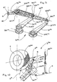
- the actual laying members essentially comprise a trailing arm system 3 1a on the one hand, and pressing devices 2 G and 2 D the other.
- the convention used is to designate similar members by the same main reference, for example "3" for the swingarm system, and to mark the specific membership of an embodiment or a variant by a number placed in superscript, for example " 1a " for the first embodiment (using a cascade of three oscillating arms), in its variant "a".
- a reference without a specific mark refers to an organ that is always the same in the different variants or must be understood as denoting all the variants of all the embodiments.
- the oscillating arm system 3 1a comprises three functional oscillating arms 31 1a, 32 1a, 33 1a arranged in cascade and an auxiliary arm 34 1a.
- This arrangement with three functional oscillating arms makes it easy to move the guide member from one bead to the other, and thus to obtain, in conjunction with the pressing devices 2 and G 2 D, an action of the apparatus one bead to another.
- An eyelet 6 constitutes in all the examples described here the materialization of the guide member of the wire 4 (without this being limiting). The eyecup is always mounted on the last swingarm.
- the oscillating arm system 31a is mounted on a plate 30a , and is described to the eyepiece 6a a movement flying over the core 1, and even bypassing it in many embodiments. In all cases, the oscillating arm system 3 makes the eyecup 6 move in a plane.
- the eyelet 6 is flared: it forms a funnel with a large opening 61 on the side of the arrival of the wire 4, and a smaller orifice 62 on the output side of the wire 4 (see also Figure 3). It is the small orifice 62 which describes a movement in said plane of movement of the guide member.
- the eyecup can be oriented so as to approximate the average orientation of the wire at the exit of the eyecup.
- the plate 30 comprises a 3D 1a 1a oscillating shaft (see 3D in Figures 10 and 11) motorizing the trailing arm system, the geometric axis of said oscillating shaft 3D 1a being located radially outside the core 1. In other words, the geometric axis of said 3D oscillating shaft 1a is located beyond the surface of the core 1, without its extension meeting the core 1. Said oscillating shaft 3D 1a does not rotate continuously, but oscillates within the limits of an arc less than 360 °, the precise value depending on the exact constitution of the oscillating arm system 3 and the intended application.
- the entire swingarm system 3 itself is quite compact. All the organs of installation, namely the oscillating arm system 3 and the pressing devices 2, including the motor and the drive mechanism, form a subset that can easily be presented to the kernel appropriately, and can be retracted for example to present to the core other devices used for the manufacture of a tire or for the evacuation of the core to other tire manufacturing stations.
- a base arm (or first arm) 31 1a ( Figure 1) is mounted on the 3D oscillating shaft 1a by a center of rotation 31R 1a .
- the first arm 31 1a comprises a transport head 31T 1a at the end opposite the center of rotation 31R 1a .
- a second arm 32 1a articulated by a center of rotation 32R 1a of the second arm, is mounted on the transport head 31T 1a of the first arm 31 1a .
- This second arm 32 1a comprises a transport head 32T 1a .
- the singular points that are the centers of rotation 31R 1a , 34R 1a and transport heads 31T 1a , 34T 1a form a parallelogram.
- these points are exactly aligned with the passage of the median position in the median plane, defined by the axis MM joining the centers of rotation 31R 1a , 34R 1a and the geometric axis of the 3D shaft (as well as by the geometric axis of the shaft 34D 1a which is of course parallel to the previous).
- the eyepiece 6 describes a movement whose path is symmetrical with respect to this median plane, and it reaches the vicinity of each of the bead zones defined on the core 1, in a perfectly symmetrical movement, even in its control. .
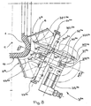
- a motor 35 controls the movement of all the arms 31 1a, 32 1a, 33 1a, 34 1a, preferably by motorization of the two shafts 1a and 3D 34D 1a, as explained in detail by means of Figures 10 and 11.
- the motor 35 1a rotates a plate 70.
- An axis 71 is embedded in the plate 70, in a predetermined eccentric position.
- the axis 71 supports a roller 72.
- a carriage 73 is translated on slides 74 arranged on the housing of the plate 30 1a .
- the carriage 73 comprises a rectilinear light 75, oriented perpendicularly to the direction of translation of the carriage 73 on the slideways 74.
- a chain (with tensioner) 76 is mounted on two identical pinions 77, and connected at its ends to the carriage 73.
- the pinions identical 77 are fixed one on the 3D shaft and the other on the shaft 34D.
- the roller 72 executes a circular motion 70R at constant speed. In doing so, the roller 72 ascends and descends in the light 75, and translates the carriage 73, thus transforming a constant-speed rotating movement in reciprocating, reciprocating and linear motion, of which the speed varies sinusoidally. Via the chain 76 and identical sprockets 77, this linear motion varying alternately is transformed on 3D trees and 34D, in oscillation sweeping an arc less than 360 °. The amplitude of the oscillation can be adjusted by adjusting the radius at which the axis 71, therefore the roller 72) is mounted eccentrically on the plate 70. At the law transformation of a movement thus created mechanically, we can of course superimpose any particular control law for the rotation of the rotor of the motor 35.
- a wire 4 is delivered by a coil (not shown) and is then threaded on a feed device 5 1a for bringing and present the wire 4 correctly to the laying members.
- the feed device 5 1a comprises means ensuring the control of the tension of the thread 4, and if necessary the necessary compensation between the delivery members 31a and the spool, because the thread is called by said laying members at a cyclically variable speed, which can even be negative.
- the wire 4 is threaded into a first ring 51 1a disposed at some distance from the plane of movement, in which the eyelet 6 performs its cyclic movement.
- the ring 51 1a is disposed centrally with respect to the core 1.
- the wire 4 is then threaded into a ring 52 attached to the second arm 32 1a .
- FIG. 2 shows more particularly the presser 2 D which comprises a fork 21 D and a hammer 22 D , both movable between a retracted position, at R (position away from the core 1), and an advanced position, at A See in ghost sight the hammer in advanced position.
- the convention used is to designate each member of the pressers by a main reference, for example "21" for the fork, and to mark the specific membership of the presser on one side, the side left or right side in Figure 1, respectively by the letter “ G " or " D " placed in superscript.
- a reference without a specific mark generically refers to one or the other of the pressers or to their organs.
- both the fork 21 and the hammer 22 have the appearance of parallel blades.
- the fork 21 is, relative to the hammer, always arranged radially on the side of the axis of rotation of the core 1.
- the fork 21 has a head 210 in "V", to take and center the wire 4.
- the plane formed by the "V” is arranged perpendicular to the wire 4.
- the blade forming the fork 21 is oriented tangentially to a circle concentric with the core 1.
- the fork 21 also includes an obviously 211 whose role will appear below.
- the hammer 22 intervenes after the fork 21 and after the so-called return phase of the eyepiece 6.
- the hammer 22 presses the wire 4 to a radial position a little higher. Preferably, it holds wire 4 while retracting the fork 21. Holding the hammer while the fork retracts helps to prevent the fork 21 from carrying with it the loop of wire 4 that has formed around one of its points 212, and which, even if it is glued to the rubber, could tend to stay supportive of the fork.
- the anchoring of the wire 4 in the bead is found perfectly reliable.
- the tilting in the advanced position, and the return to the retracted position, both for the fork 21 and for the hammer 22, are controlled in synchronism with the oscillating arm system 31a , by any suitable device (movement reversal).
- the 3D shaft by a suitable mechanical transmission, for example by belt or cable or by electrical synchronization between several motors).
- a device or an equivalent device is simply shown schematically by an arrow, and designated by the reference 2, it being understood that this refers generally to a device with two actuators such as a fork and a hammer, intervening in sequence on the wire 4.
- FIG. 3 shows an alternative embodiment of the same first embodiment, comprising a swing arm system 3 1b , different from that described above essentially by the means for controlling the movement of the second arm 32 1b relative to the base arm (or first arm) 31 1b .
- the arm system 3 1b further comprises three functional arms 31 1b , 32 1b , 33 1b arranged in cascade, and said control means also allow, in conjunction with pressing devices, an action of the device from one bead to another.
- a base arm (or first arm) 31 1b is mounted on a 3D oscillating shaft 1b by a center of rotation 31R 1b .
- the first arm 31 1b comprises a transport head 31T 1b at the end opposite the center of rotation 31R 1b .
- a second arm 32 1b articulated by a center of rotation 32R 1b of the second arm, is mounted on the transport head 31T 1b of the first arm 31 1b .
- This second arm 32 1b comprises a transport head 32T 1b .
- the apparatus comprises a third arm 33 1b articulated by its center of rotation 33R 1b on the transport head 32T 1b of the second arm 32 1b .
- This third arm 33 1b comprises a transport head LP 1b , on which is directly mounted the eyelet 6.
- the driving pulley 311 1b centered on the center of rotation 31R 1b of said first arm.
- the driving pulley 311 1b is integral with a flange 37 1b fixedly mounted on said plate (not shown in Figure 3).
- a driven pulley 312 1b is integral (that is to say without possible relative rotation) of the second arm 32 1b .
- a toothed belt 361 1b connects said driving pulley and driven pulley.
- the diameters of the driving pulley and driven pulley are identical so that, during its movement, the second arm 32 1b always remains parallel to itself.
- the belts also notched, work without relative sliding relative to the pulleys on which they are mounted.
- the terms "pulley” and “belt” encompass all equivalent systems to control relative positions without slippage.
- the flange 37 1b is fixed in space, but more generally, it is important that its angular position is controlled independently of the oscillation control of said first arm. For example, it is possible to introduce a degree of freedom between the plate and the flange 37 1b , and to control the relative position of said puddle 37 1b with respect to the plate, in order to act selectively on the spatial position of the driving pulley 311 1b so as to for example, adapting the movement executed by the eyecup 6 to shapes of different sizes.
- the means for controlling the relative position of the third arm 33 1b relative to the second arm 32 1b essentially comprise a driving pulley 321 1b centered on the center of rotation 32R 1b of said second arm 32 1b , integral (no relative rotation possible) of the first arm 31 1b , and they comprise a driven pulley 322 1b integral (likewise, no possible relative rotation) of said third arm 33 1b .
- a toothed belt 362 1b connects said driving pulley and driven pulley.
- the driving pulley 321 1b could also be mounted free with respect to the first arm 31 1b , and driven by a belt wound on the one hand on a pulley integral with said driving pulley 321 1b and on the other hand rolled on another pulley (not shown) concentric with the 3D geometric axis 1b and motorized independently of both the movement of the first arm and the movement of the pulley 311 1b .
- This provides more latitude to control relative movement of the third arm relative to the second arm.
- FIG. 5 illustrates an equivalent control, mounted on the oscillating arm system 31a of FIG. 1.
- a third pulley 321 is seen centered on the intermediate center of rotation 32I 1a of said second arm 32 1a , integral (no relative rotation possible) of the intermediate arm 34 1a , and a fourth pulley 322 1a integral (likewise, no possible relative rotation) of said third arm 33 1a .
- a toothed belt 362 1a connects said driving pulley and driven pulley.
- the diameters of the driving pulley and driven pulley are different, their respective values being calculated so that the LP transport end 1a , during its movement, reaches the zone of the core 1 close to the bead (see FIG. 4), without the second arm 32 1a do not hit the flank 11 of the core 1.
- the previous remark on another possibility of controlling the relative movement of the third arm relative to the second also applies to this variant.
- the intermediate arm 34 1a passes over the first arm 31 1a . It is therefore appropriate for the arms to be correctly superimposed so that this movement is possible. This is the role of the spacers 381 1a and 382 1a . This remark is, of course, of general importance.
- the oscillating arms articulated to each other, in so far as they perform a symmetrical movement in its path relative to a median plane, must be judiciously superimposed on each other to allow all the desired arm crossings.
- the arm system 31c further comprises three functional arms 31c , 32c , 33c arranged in cascade, and said control also makes it possible, in conjunction with pressing devices, for an action of apparatus from one bead to another.
- This third arm 33 1c comprises a LP transport head 1c , on which is directly mounted the eyelet 6.
- a cam 381 1c is machined in the transport head 31T 1c of the first arm 31 1c .
- the cam comprises a neutral section 381N 1c machined at a constant mean radius, a final control section 381A 1c with increasing radius, for controlling the relative movement of the third arm 33c on one side of the core, and a final control section 381B. 1c decreasing radius, to control the relative movement of the third arm 33 1c on the other side of the core.
- a toothed wheel 322 1c is mounted on the center of rotation 33R 1c of the third arm 33 1c , and is integral (no possible relative rotation) of said third arm 33 1c .
- a rod 383 1c slides in a guide 384 1c integral with the second arm 32 1c .
- the rod 383 1c is thus guided in sliding relative to the second arm 32 1c .
- the rod 383 1c carries on one side a cam follower 382 1c cooperating with said cam 381 1c .
- the rod 383 1c comprises a rack 385 1c which is engaged on said toothed wheel 322 1c .
- the relative movement between second and third arms can be adjusted to the needs fairly freely since it depends essentially on the profile of the cam. It is thus freed from the proportionality constraint relative rotational movement between the first and the second arm, specific to the belt drive described with the help of Figures 3 and 5. It can impose a relative position of the third arm relative to the second arm, so in particular to quickly clear the eyecup 6 relative to the core 1. This ensures a constantly sufficient guard between the LP transport head 1c and the core 1 (see positions 6b, 6c and 6d), while by approaching sufficiently the surface of the core 1 in the area of the bead (see position 6a).
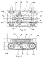
- the control motor 35 2a actuates 3D shafts 2a and 34D 2a whose geometrical axis of rotation is included in a median plane M 2a -M 2a .
- the control 35 actuates motor 2a as the pressing devices 2 and G 2 D, the latter being of the same type as those whose form is described in more detail in Figure 2.
- the spacing of the presser 2 and G 2 D devices relative to the median plane M 2a -M 2a can be set by the knobs 23 2a and 24 2a .
- a parallelogram is formed in this example by means of an auxiliary arm 34 2a mounted oscillating about the oscillating shaft 34D 2a through its center. rotation 34R 2a .
- the center of rotation 34R 2a is located outside the surface of the core 1, between the latter and the center of rotation 31R 2a of the first arm 31 2a .
- the auxiliary arm 34 2a comprises a transport head 34T 2a articulated on the second arm 32 2a which comprises for this purpose an intermediate center of rotation 32I 2a situated between the center of rotation 32R 2a and the transport head 32T 2a of said second arm 32 2a .
- the transport head 32T 2a of the second arm 32 2a directly supports the eyecup 6.
- the movement of the eyecup 6 is represented by the center line 63 2a .
- An apparatus according to this principle could equally well be used for bead action to any point under the tread, including up to the opposite shoulder, with some degree of overlap of half-carcasses one over the other.
- Figure 9 is shown a variant comprising a system with oscillating arms 32b different from that described for the system of Figure 8 essentially by the control means of the movement of the second arm 32 2b relative to the base arm (or first arm) 31 2b .
- this variant comprises a drive gear 311 2b centered on the center of rotation 31R 2b of said first arm.
- a base arm (or first arm) 31 2b is mounted on an oscillating shaft by its center of rotation 31R 2b .
- the first arm 31 2b comprises a transport head 31T 2b at the end opposite the center of rotation 31R 2b .
- a second arm 32 2b articulated by a center of rotation 32R 2b of the second arm, is mounted on the transport head 31T 2b of the first arm 31 2b .
- This second arm 32 2b comprises a transport head 32T 2b which is directly mounted on the eyelet 6.
- the driving gear 311 2b is integral with a flange 37 2b fixedly mounted on a plate (not shown in Figure 9).
- a driven gear 312 2b is integral (that is to say without possible relative rotation) of the second arm 32 2b .
- a chain 361 2b connects said first and second gears.
- the diameters of the first and second pinions are identical so that, during its movement, the second arm 32 2b always remains parallel to itself.
- the arm system 32b can substitute for the arm system 32a of FIG. 8.
- the eyepiece 6 in all the variants, is animated by a cyclical movement in a plan, called above "eyepiece movement plan".
- the pre-coated surface of the Core 1 determines the overall geometry of the laying surface of the reinforcing wire 4.
- the core 1 is rotated about its axis while the eyecup 6 goes back and forth in the eyepiece movement plane.
- the movement of the nucleus 1 is in synchronism with the back and forth movement of the eyepiece.
- the actual trajectory of the hoops 40 of the yarn 4 is therefore both a function of the relative position between the eyepiece movement plane and the nucleus, and is a function of the relative movement between the nucleus 1 and the comings and goings of the eyecup 6.
- the trajectory of the arch 40 is substantially radial because it describes the production of a carcass (or half-carcass) for a radial tire, without, of course, this is not limiting.
- Another example is given in a third embodiment, illustrated in FIG. 12, where the trajectory of the arch 40 3a is not radial, but forms a typical angle of the belt reinforcements (of the order of 15 ° at 30 °).
Landscapes
- Engineering & Computer Science (AREA)
- Mechanical Engineering (AREA)
- Tyre Moulding (AREA)
- Ropes Or Cables (AREA)
- Woven Fabrics (AREA)
- Heating, Cooling, Or Curing Plastics Or The Like In General (AREA)
- Yarns And Mechanical Finishing Of Yarns Or Ropes (AREA)
Claims (11)
- Vorrichtung zur Herstellung einer Verstärkung für einen Reifen, wobei die Vorrichtung dazu dient, eine Verstärkung herzustellen, die aus einer Faser (4) besteht, die kontinuierlich und je nach Bedarf durch eine geeignete Verteilervorrichtung bereitgestellt wird, wobei die Vorrichtung dazu dient, in Zusammenhang mit einer im Wesentlichen toroidalen Form eingesetzt zu werden, auf der man diese Verstärkung nach und nach aufbaut, indem man Bögen der Faser auf einer gewünschten Trajektorie für die Faser auf der Oberfläche dieser Form ablegt, wobei die Vorrichtung umfasst:dadurch gekennzeichnet, dass die Einrichtungen zum Verschieben wenigstens zwei Arme (31, 32) umfassen, die jeweils um eine geometrische Drehachse oszillieren, wobei die geometrischen Drehachsen von jedem der beiden Arme parallel sind, nämlich ein oszillierender Basisarm und wenigstens ein weiterer oszillierender Arm, wobei die wenigstens zwei Arme jeweils einen Drehpunkt (31R, 32R) und einen Transportkopf (31T, 32T) sowie Steuereinrichtungen aufweisen, um die Arme in oszillierende Bewegungen um ihre jeweiligen geometrischen Drehachsen zu versetzen, wobei die Vorrichtung so eingerichtet ist, dass der Transportkopf des Basisarms den Drehpunkt eines zweiten oszillierenden Armes trägt und dass der Transportkopf des zweiten oszillierenden Armes direkt oder indirekt das Führungselement von dem einen zu dem anderen Ende der Trajektorie transportiert, wobei die Vorrichtung Einrichtungen zum Steuern der relativen Position des zweiten Arms in Bezug auf den Basisarm umfasst.ein Führungselement (6), in welchem die Faser frei gleiten kann, Einrichtungen zum Verschieben des Führungselements in einer zyklischen Hin- und Herbewegung, um in aufeinander folgenden Zyklen das Führungselement in die Nähe jedes gewünschten Endes der Trajektorie für die Faser zu bringen,Pressfinger (2) in der Nähe von jedem Ende der Trajektorie, um die Faser auf der Form an den Enden zu legen,
- Vorrichtung nach Anspruch 1, bei der die Steuereinrichtungen für die relative Position des zweiten Arms (32) in Bezug auf den Basisarm (31) im Wesentlichen eine treibende Rolle (311) umfassen, die auf dem Drehpunkt des Basisarms zentriert ist, wobei die Winkelposition der treibenden Rolle unabhängig von der Steuerung der Oszillation des Basisarms gesteuert wird, und eine getriebene Rolle (312) umfassen, die mit dem zweiten Arm fest verbunden ist, wobei ein gezahnter Treibriemen (361) die Rollen verbindet.
- Vorrichtung nach Anspruch 4, bei der die treibende Rolle (311) raumfest ist.
- Vorrichtung nach Anspruch 1 mit einem Hilfsarm (34), der um einen Drehpunkt (34R) oszilliert, wobei die geometrische Drehachse des Drehpunktes des Hilfsarms vollständig außerhalb der Oberfläche der Form gelegen ist, zwischen dieser und der geometrischen Drehachse des Basisarms, wobei der Hilfsarm einen Transportkopf (34T) umfasst, wobei der zweite Arm einen Zwischendrehpunkt (32I) zwischen dem Drehpunkt (32R) des zweiten Arms und dem Transportkopf (32T) des zweiten Arms aufweist, wobei der Zwischendrehpunkt beweglich an dem Transportkopf (34T) des Hilfsarms angebracht ist.
- Vorrichtung nach Anspruch 1 oder 4, bei der der Transportkopf (32T) des zweiten Arms direkt das Führungselement (6) trägt.
- Vorrichtung nach einem der Ansprüche 1 bis 4, die einen dritten oszillierenden Arm (33) umfasst, der über seinen Drehpunkt (33R) mit dem Transportkopf (32T) des zweiten Armes beweglich befestigt ist, wobei der dritte Arm einen Transportkopf (33T) hat, um direkt oder indirekt das Führungselement von einem Ende zum anderen der Trajektorie zu transportieren, und Einrichtungen zum Vorgeben der relativen Position des dritten Arms in Bezug auf den zweiten Arm umfasst.
- Vorrichtung nach Anspruch 6, bei der der Transportkopf (33T) des dritten Arms direkt das Führungselement (6) trägt.
- Vorrichtung nach Anspruch 6 und 2 oder 7 und 2, bei der die Steuereinrichtungen für die relative Position des dritten Arms in Bezug auf den zweiten Arm im Wesentlichen eine treibende Rolle (321) umfassen, die auf dem Drehpunkt (32R) des zweiten Arms zentriert ist, wobei die treibende Rolle fest mit dem Basisarm (31) verbunden ist, und die eine getriebene Rolle (322) umfassen, die fest mit dem dritten Arm (33) am Drehpunkt desselben verbunden ist, wobei ein gezahnter Treibriemen (362) die antreibende Rolle und die getriebene Rolle verbindet.
- Vorrichtung nach Anspruch 6 und 4 oder 7 und 4, bei der die Steuereinrichtungen der relativen Position des dritten Arms in Bezug auf den zweiten Arm im Wesentlichen eine treibende Rolle (321) umfassen, die auf dem Zwischendrehpunkt (32I) des zweiten Arms zentriert ist, wobei die treibende Rolle fest mit dem Zwischenarm (34) verbunden ist, und die eine getriebene Rolle (322) umfassen, die fest mit dem dritten Arm (33) am Drehpunkt desselben verbunden ist, wobei ein gezahnter Treibriemen (362) die treibende Rolle und die getriebene Rolle verbindet.
- Vorrichtung nach Anspruch 6 oder 7, bei der die Steuereinrichtungen für die relative Position des dritten Arms in Bezug auf den zweiten Arm im Wesentlichen einen Nocken umfassen, der in den Transportkopf des Basisarms eingebaut ist, ein gezahntes Rad, das fest mit dem dritten Arm verbunden ist, einen Schwingarm, der gleitend in Bezug auf den zweiten Arm geführt wird, der auf einer Seite einen Nockenfolger trägt, der in dem Nocken eingehakt ist, und auf der anderen Seite eine Zahnstange, die mit dem gezahnten Rad zusammenwirkt.
- Vorrichtung nach einem der Ansprüche 1 bis 10 mit einem Träger für Verschiebeeinrichtungen des Führungselements und mit Einrichtungen, um den Träger in eine alternierende Bewegung zu versetzen, so dass die Trajektorie für die Positionierung der Faser (4) auf dem Kern (1) gekrümmt werden kann.
Priority Applications (1)
| Application Number | Priority Date | Filing Date | Title |
|---|---|---|---|
| EP04015938A EP1464472B1 (de) | 2000-02-01 | 2001-01-25 | Schwingarmvorrichtung zur Herstellung einer Reifenverstärkungsstruktur mit einem einzigen Reifenkord |
Applications Claiming Priority (2)
| Application Number | Priority Date | Filing Date | Title |
|---|---|---|---|
| FR0001393 | 1993-02-01 | ||
| FR0001393A FR2804367B1 (fr) | 2000-02-01 | 2000-02-01 | Appareil a bras oscillant, pour la fabrication d'un renfort de pneumatique a partir d'un seul fil |
Related Child Applications (1)
| Application Number | Title | Priority Date | Filing Date |
|---|---|---|---|
| EP04015938A Division EP1464472B1 (de) | 2000-02-01 | 2001-01-25 | Schwingarmvorrichtung zur Herstellung einer Reifenverstärkungsstruktur mit einem einzigen Reifenkord |
Publications (3)
| Publication Number | Publication Date |
|---|---|
| EP1122057A2 EP1122057A2 (de) | 2001-08-08 |
| EP1122057A3 EP1122057A3 (de) | 2003-05-02 |
| EP1122057B1 true EP1122057B1 (de) | 2005-06-29 |
Family
ID=8846642
Family Applications (2)
| Application Number | Title | Priority Date | Filing Date |
|---|---|---|---|
| EP04015938A Expired - Lifetime EP1464472B1 (de) | 2000-02-01 | 2001-01-25 | Schwingarmvorrichtung zur Herstellung einer Reifenverstärkungsstruktur mit einem einzigen Reifenkord |
| EP01101614A Expired - Lifetime EP1122057B1 (de) | 2000-02-01 | 2001-01-25 | Schwingarmvorrichtung zur Herstellung einer Reifenverstärkungsstruktur mit einem einzigen Reifenkord |
Family Applications Before (1)
| Application Number | Title | Priority Date | Filing Date |
|---|---|---|---|
| EP04015938A Expired - Lifetime EP1464472B1 (de) | 2000-02-01 | 2001-01-25 | Schwingarmvorrichtung zur Herstellung einer Reifenverstärkungsstruktur mit einem einzigen Reifenkord |
Country Status (9)
| Country | Link |
|---|---|
| US (1) | US6463978B2 (de) |
| EP (2) | EP1464472B1 (de) |
| JP (1) | JP2001260245A (de) |
| KR (1) | KR100724296B1 (de) |
| CN (1) | CN1311094A (de) |
| AT (2) | ATE298660T1 (de) |
| BR (1) | BR0100238A (de) |
| DE (2) | DE60111656T2 (de) |
| FR (1) | FR2804367B1 (de) |
Cited By (1)
| Publication number | Priority date | Publication date | Assignee | Title |
|---|---|---|---|---|
| CN1741897B (zh) * | 2003-01-23 | 2010-06-16 | 米其林技术公司 | 用于生产轮胎增强件的带有引导环的设备 |
Families Citing this family (24)
| Publication number | Priority date | Publication date | Assignee | Title |
|---|---|---|---|---|
| KR100386641B1 (ko) * | 2000-07-19 | 2003-06-02 | 한국기계연구원 | 타이어의 카커스 제조장치 |
| DE60207119T2 (de) * | 2001-02-07 | 2006-07-27 | Société de Technologie Michelin | Vorrichtung mit Schwingarm zur Herstellung einer Luftreifenverstärkung aus einem Draht |
| DE60218771T2 (de) | 2001-02-07 | 2007-12-13 | Société de Technologie Michelin | Schwingarmvorrichtung zur Herstellung einer Reifenverstärkungsstruktur mit einem einzigen Reifenkord |
| FR2827806A1 (fr) * | 2001-07-26 | 2003-01-31 | Michelin Soc Tech | Appareil de fabrication d'un renforcement pour pneumatique |
| EP1517781B1 (de) * | 2002-06-03 | 2007-04-04 | Société de Technologie Michelin | Vorrichtung zur herstellung einer verstärkungsstruktur für einen reifen mit einem wulstfahnendrehmechanismus |
| CN1711164A (zh) * | 2002-10-01 | 2005-12-21 | 株式会社普利司通 | 形成轮胎的帘线增强层的方法和设备 |
| FR2848141A1 (fr) * | 2002-12-04 | 2004-06-11 | Michelin Soc Tech | Appareil de fabrication d'un renforcement pour pneumatique, a bras de pose multiples comportant un mouvement guide par un suiveur de came coulissant dans une lumiere |
| ES2268257T3 (es) | 2002-12-04 | 2007-03-16 | Societe De Technologie Michelin | Aparato para la fabricacion de un elemento de refuerzo para neumaticos de gran anchura. |
| US20040154727A1 (en) * | 2003-02-11 | 2004-08-12 | Weissert James Thomas | Method and apparatus for manufacturing carcass plies for a tire |
| EP1827805B1 (de) * | 2004-12-01 | 2008-09-10 | Pirelli Tyre S.p.A. | Verfahren und vorrichtung zur steuerung eines herstellungsprozesses von komponenten eines reifens für fahrzeugräder |
| US7686053B2 (en) * | 2005-12-01 | 2010-03-30 | The Goodyear Tire & Rubber Company | Cord tensioning and feed mechanism for a tire cord applicator head |
| US20070125482A1 (en) * | 2005-12-01 | 2007-06-07 | Weissert James T | Bi-directional tooling head and method for tire cord application |
| US20070125478A1 (en) * | 2005-12-01 | 2007-06-07 | Weissert James T | Tire cord application station and method |
| US7753098B2 (en) * | 2005-12-01 | 2010-07-13 | The Goodyear Tire & Rubber Company | Spring loaded tooling head and method for tire cord application |
| US20070125471A1 (en) * | 2005-12-01 | 2007-06-07 | Weissert James T | Split cord geodesic configurations for a tire |
| US7740039B2 (en) * | 2005-12-01 | 2010-06-22 | The Goodyear Tire & Rubber Company | Cord cutting mechanism and method for a tire cord applicator head |
| US8578994B2 (en) | 2006-12-19 | 2013-11-12 | The Goodyear Tire & Rubber Company | Applicator head for tire cord construction |
| FR2924702B1 (fr) * | 2007-12-07 | 2010-05-07 | Michelin Soc Tech | Dispositif de regulation d'un debit de defilement d'un element lineaire. |
| DE102012004463A1 (de) * | 2012-03-08 | 2013-09-12 | Herbert Kannegiesser Gmbh | Vorrichtung und Verfahren zum Zuführen von Wäschestücken zu einer Mangel oder dergleichen |
| CN104200988A (zh) * | 2014-09-02 | 2014-12-10 | 中江县凯讯电子有限公司 | 利于线轮绕线质量的绕线装置 |
| CN104200989A (zh) * | 2014-09-02 | 2014-12-10 | 中江县凯讯电子有限公司 | 用于线轮绕线的机构 |
| DE102017124983A1 (de) * | 2017-10-25 | 2019-04-25 | Maschinenfabrik Rieter Ag | Changiereinheit, Verfahren zum Betreiben einer Changiereinheit sowie Arbeitsstelle mit einer Changiereinheit |
| CN108972184B (zh) * | 2018-08-22 | 2020-06-02 | 宁波高新区意川汽车零部件有限公司 | 一种打磨轮胎内外壁装置 |
| CN115625620B (zh) * | 2022-12-21 | 2023-04-11 | 常州市腾纳机械有限公司 | 一种钢管支架加工用钢管抛光机以及抛光方法 |
Family Cites Families (12)
| Publication number | Priority date | Publication date | Assignee | Title |
|---|---|---|---|---|
| US1259997A (en) * | 1916-11-06 | 1918-03-19 | Walter Kline | Tire-cording machine. |
| US1728957A (en) * | 1923-03-16 | 1929-09-24 | Dickinson Cord Tire Corp | Cord-tire-making machine |
| GB900994A (en) * | 1957-08-05 | 1962-07-11 | Pirelli | Method of tracing the profile of a cam for use on a machine for forming on a collapsible drum annular bands suitable as reinforcements for the casing of vehicle wheel tyres |
| LU36075A1 (de) * | 1957-11-27 | |||
| IN157253B (de) * | 1980-10-16 | 1986-02-15 | Bates W & A Ltd | |
| FR2597784B1 (fr) * | 1986-04-25 | 1990-10-26 | Michelin & Cie | Procede et appareil de fabrication de renforcements pour pneumatiques |
| AT390762B (de) * | 1988-09-30 | 1990-06-25 | Lim Kunststoff Tech Gmbh | Vorrichtung zum umwickeln eines kernes zum einlegen in eine form zur herstellung von luftreifen |
| EP0580055B1 (de) * | 1992-07-21 | 1997-01-22 | Sedepro | Verfahren und Vorrichtung zum Anordnen eines einfädigen Verstärkungsdrahtes auf einen Kern bei der Herstellung von Reifenkarkassen |
| DE69810200T2 (de) | 1997-07-08 | 2003-11-13 | Bridgestone Corp., Tokio/Tokyo | Verfahren und Vorrichtung zum Aufbauen einer torusförmigen Reifenkarkasse |
| JP3850968B2 (ja) * | 1998-01-07 | 2006-11-29 | 株式会社ブリヂストン | タイヤ補強コード配設装置および方法 |
| JP4233658B2 (ja) * | 1998-06-01 | 2009-03-04 | 株式会社ブリヂストン | カーカスコードの貼付け装置およびタイヤの製造方法 |
| FR2804368A1 (fr) * | 2000-02-01 | 2001-08-03 | Sedepro | Appareil pour la fabrication de renforts pour pneumatique |
-
2000
- 2000-02-01 FR FR0001393A patent/FR2804367B1/fr not_active Expired - Fee Related
-
2001
- 2001-01-25 DE DE60111656T patent/DE60111656T2/de not_active Expired - Lifetime
- 2001-01-25 EP EP04015938A patent/EP1464472B1/de not_active Expired - Lifetime
- 2001-01-25 AT AT01101614T patent/ATE298660T1/de not_active IP Right Cessation
- 2001-01-25 EP EP01101614A patent/EP1122057B1/de not_active Expired - Lifetime
- 2001-01-25 AT AT04015938T patent/ATE393012T1/de not_active IP Right Cessation
- 2001-01-25 DE DE60133780T patent/DE60133780T2/de not_active Expired - Lifetime
- 2001-01-31 KR KR1020010004498A patent/KR100724296B1/ko not_active IP Right Cessation
- 2001-01-31 JP JP2001023294A patent/JP2001260245A/ja active Pending
- 2001-01-31 BR BR0100238-4A patent/BR0100238A/pt active Search and Examination
- 2001-02-01 CN CN01116552A patent/CN1311094A/zh not_active Withdrawn
- 2001-02-01 US US09/773,985 patent/US6463978B2/en not_active Expired - Lifetime
Cited By (1)
| Publication number | Priority date | Publication date | Assignee | Title |
|---|---|---|---|---|
| CN1741897B (zh) * | 2003-01-23 | 2010-06-16 | 米其林技术公司 | 用于生产轮胎增强件的带有引导环的设备 |
Also Published As
| Publication number | Publication date |
|---|---|
| EP1464472A3 (de) | 2005-07-06 |
| JP2001260245A (ja) | 2001-09-25 |
| EP1122057A3 (de) | 2003-05-02 |
| US20010020518A1 (en) | 2001-09-13 |
| EP1464472B1 (de) | 2008-04-23 |
| CN1311094A (zh) | 2001-09-05 |
| EP1122057A2 (de) | 2001-08-08 |
| ATE393012T1 (de) | 2008-05-15 |
| DE60133780T2 (de) | 2009-05-07 |
| DE60133780D1 (de) | 2008-06-05 |
| ATE298660T1 (de) | 2005-07-15 |
| KR20010078188A (ko) | 2001-08-20 |
| KR100724296B1 (ko) | 2007-06-04 |
| EP1464472A2 (de) | 2004-10-06 |
| DE60111656D1 (de) | 2005-08-04 |
| DE60111656T2 (de) | 2006-05-04 |
| US6463978B2 (en) | 2002-10-15 |
| FR2804367A1 (fr) | 2001-08-03 |
| BR0100238A (pt) | 2001-08-28 |
| FR2804367B1 (fr) | 2002-09-20 |
Similar Documents
| Publication | Publication Date | Title |
|---|---|---|
| EP1122057B1 (de) | Schwingarmvorrichtung zur Herstellung einer Reifenverstärkungsstruktur mit einem einzigen Reifenkord | |
| EP0580055B1 (de) | Verfahren und Vorrichtung zum Anordnen eines einfädigen Verstärkungsdrahtes auf einen Kern bei der Herstellung von Reifenkarkassen | |
| EP1231050B1 (de) | Vorrichtung mit Schwingarm zur Herstellung einer Luftreifenverstärkung aus einem Draht | |
| EP1122055B1 (de) | Gerät mit kombinierten Bewegungen zur Herstellung einer Reifenverstärkung auf der Basis eines Einzeldrahtes | |
| EP0582215B1 (de) | Verfahren zum Herstellen von Reifen und Vorrichtung zum Herstellen einer Reifengürtelverstärkung | |
| CA2071445C (fr) | Procede de fabrication d'un pneumatique et machines pour la mise en oeuvre de ce procede | |
| EP0519295B1 (de) | Verfahren zum Herstellen eines Reifens und Apparat zur Durchführung des Verfahrens | |
| EP1231049B1 (de) | Schwingarmvorrichtung zur Herstellung einer Reifenverstärkungsstruktur mit einem einzigen Reifenkord | |
| EP1517781A1 (de) | Vorrichtung zur herstellung einer verstärkungsstruktur für einen reifen mit einem wulstfahnendrehmechanismus | |
| EP1711335B1 (de) | Verfahren und vorrichtung zur herstellung einer reifenverstärkung | |
| WO2003101714A2 (fr) | Fabrication d’une structure de renforcement pour pneumatique avec controle volumetrique de la matrice | |
| EP1426170A2 (de) | Vorrichtung mit mehreren Auftragungsarmen zur Herstellung eines Verstärkungselements für Luftreifen | |
| EP1590169B1 (de) | Eine mit einer drahtführungseinrichtung ausgerüstete vorrichtung zur herstellung von verstärkungselementen für luftreifen und ein herstellungsverfahren unter verwendung einer solchen vorrichtung. | |
| EP1426169B1 (de) | Vorrichtung zur Herstellung eines Verstärkungselements für grossformatige Luftreifen | |
| EP1279484B1 (de) | Verfahren und Vorrichtung zur Herstellung einer Reifenverstärkungsstruktur | |
| EP0353511A1 (de) | Bestandteile einer Vorrichtung zum Herstellen einer Reifenverstärkung | |
| EP1824666B1 (de) | Vorrichtung zur herstellung einer verstärkung für einen luftreifen |
Legal Events
| Date | Code | Title | Description |
|---|---|---|---|
| PUAI | Public reference made under article 153(3) epc to a published international application that has entered the european phase |
Free format text: ORIGINAL CODE: 0009012 |
|
| AK | Designated contracting states |
Kind code of ref document: A2 Designated state(s): AT BE CH CY DE DK ES FI FR GB GR IE IT LI LU MC NL PT SE TR |
|
| AX | Request for extension of the european patent |
Free format text: AL;LT;LV;MK;RO;SI |
|
| PUAL | Search report despatched |
Free format text: ORIGINAL CODE: 0009013 |
|
| AK | Designated contracting states |
Designated state(s): AT BE CH CY DE DK ES FI FR GB GR IE IT LI LU MC NL PT SE TR |
|
| AX | Request for extension of the european patent |
Extension state: AL LT LV MK RO SI |
|
| 17P | Request for examination filed |
Effective date: 20031103 |
|
| 17Q | First examination report despatched |
Effective date: 20031201 |
|
| AKX | Designation fees paid |
Designated state(s): AT BE CH CY DE DK ES FI FR GB GR IE IT LI LU MC NL PT SE TR |
|
| GRAP | Despatch of communication of intention to grant a patent |
Free format text: ORIGINAL CODE: EPIDOSNIGR1 |
|
| RAP1 | Party data changed (applicant data changed or rights of an application transferred) |
Owner name: SEDEPRO |
|
| GRAS | Grant fee paid |
Free format text: ORIGINAL CODE: EPIDOSNIGR3 |
|
| GRAA | (expected) grant |
Free format text: ORIGINAL CODE: 0009210 |
|
| AK | Designated contracting states |
Kind code of ref document: B1 Designated state(s): AT BE CH CY DE DK ES FI FR GB GR IE IT LI LU MC NL PT SE TR |
|
| PG25 | Lapsed in a contracting state [announced via postgrant information from national office to epo] |
Ref country code: IE Free format text: LAPSE BECAUSE OF FAILURE TO SUBMIT A TRANSLATION OF THE DESCRIPTION OR TO PAY THE FEE WITHIN THE PRESCRIBED TIME-LIMIT Effective date: 20050629 Ref country code: FI Free format text: LAPSE BECAUSE OF FAILURE TO SUBMIT A TRANSLATION OF THE DESCRIPTION OR TO PAY THE FEE WITHIN THE PRESCRIBED TIME-LIMIT Effective date: 20050629 Ref country code: AT Free format text: LAPSE BECAUSE OF FAILURE TO SUBMIT A TRANSLATION OF THE DESCRIPTION OR TO PAY THE FEE WITHIN THE PRESCRIBED TIME-LIMIT Effective date: 20050629 |
|
| REG | Reference to a national code |
Ref country code: GB Ref legal event code: FG4D Free format text: NOT ENGLISH |
|
| REG | Reference to a national code |
Ref country code: CH Ref legal event code: EP |
|
| REF | Corresponds to: |
Ref document number: 60111656 Country of ref document: DE Date of ref document: 20050804 Kind code of ref document: P |
|
| REG | Reference to a national code |
Ref country code: IE Ref legal event code: FG4D Free format text: LANGUAGE OF EP DOCUMENT: FRENCH |
|
| PG25 | Lapsed in a contracting state [announced via postgrant information from national office to epo] |
Ref country code: GR Free format text: LAPSE BECAUSE OF FAILURE TO SUBMIT A TRANSLATION OF THE DESCRIPTION OR TO PAY THE FEE WITHIN THE PRESCRIBED TIME-LIMIT Effective date: 20050929 Ref country code: SE Free format text: LAPSE BECAUSE OF FAILURE TO SUBMIT A TRANSLATION OF THE DESCRIPTION OR TO PAY THE FEE WITHIN THE PRESCRIBED TIME-LIMIT Effective date: 20050929 Ref country code: DK Free format text: LAPSE BECAUSE OF FAILURE TO SUBMIT A TRANSLATION OF THE DESCRIPTION OR TO PAY THE FEE WITHIN THE PRESCRIBED TIME-LIMIT Effective date: 20050929 |
|
| PG25 | Lapsed in a contracting state [announced via postgrant information from national office to epo] |
Ref country code: ES Free format text: LAPSE BECAUSE OF FAILURE TO SUBMIT A TRANSLATION OF THE DESCRIPTION OR TO PAY THE FEE WITHIN THE PRESCRIBED TIME-LIMIT Effective date: 20051010 |
|
| GBT | Gb: translation of ep patent filed (gb section 77(6)(a)/1977) |
Effective date: 20050919 |
|
| PG25 | Lapsed in a contracting state [announced via postgrant information from national office to epo] |
Ref country code: PT Free format text: LAPSE BECAUSE OF FAILURE TO SUBMIT A TRANSLATION OF THE DESCRIPTION OR TO PAY THE FEE WITHIN THE PRESCRIBED TIME-LIMIT Effective date: 20051207 |
|
| REG | Reference to a national code |
Ref country code: IE Ref legal event code: FD4D |
|
| PG25 | Lapsed in a contracting state [announced via postgrant information from national office to epo] |
Ref country code: CH Free format text: LAPSE BECAUSE OF NON-PAYMENT OF DUE FEES Effective date: 20060131 Ref country code: BE Free format text: LAPSE BECAUSE OF NON-PAYMENT OF DUE FEES Effective date: 20060131 Ref country code: LI Free format text: LAPSE BECAUSE OF NON-PAYMENT OF DUE FEES Effective date: 20060131 Ref country code: MC Free format text: LAPSE BECAUSE OF NON-PAYMENT OF DUE FEES Effective date: 20060131 |
|
| PLBE | No opposition filed within time limit |
Free format text: ORIGINAL CODE: 0009261 |
|
| STAA | Information on the status of an ep patent application or granted ep patent |
Free format text: STATUS: NO OPPOSITION FILED WITHIN TIME LIMIT |
|
| 26N | No opposition filed |
Effective date: 20060330 |
|
| NLS | Nl: assignments of ep-patents |
Owner name: MANUFACTURE FRANEAISE DES PNEUMATIQUES MICHELIN Effective date: 20060622 |
|
| REG | Reference to a national code |
Ref country code: FR Ref legal event code: TP |
|
| REG | Reference to a national code |
Ref country code: CH Ref legal event code: PL |
|
| REG | Reference to a national code |
Ref country code: GB Ref legal event code: 732E |
|
| BERE | Be: lapsed |
Owner name: SEDEPRO Effective date: 20060131 |
|
| PGFP | Annual fee paid to national office [announced via postgrant information from national office to epo] |
Ref country code: GB Payment date: 20080124 Year of fee payment: 8 Ref country code: LU Payment date: 20080115 Year of fee payment: 8 Ref country code: NL Payment date: 20080115 Year of fee payment: 8 |
|
| PG25 | Lapsed in a contracting state [announced via postgrant information from national office to epo] |
Ref country code: TR Free format text: LAPSE BECAUSE OF FAILURE TO SUBMIT A TRANSLATION OF THE DESCRIPTION OR TO PAY THE FEE WITHIN THE PRESCRIBED TIME-LIMIT Effective date: 20050629 |
|
| PG25 | Lapsed in a contracting state [announced via postgrant information from national office to epo] |
Ref country code: CY Free format text: LAPSE BECAUSE OF FAILURE TO SUBMIT A TRANSLATION OF THE DESCRIPTION OR TO PAY THE FEE WITHIN THE PRESCRIBED TIME-LIMIT Effective date: 20050629 |
|
| GBPC | Gb: european patent ceased through non-payment of renewal fee |
Effective date: 20090125 |
|
| NLV4 | Nl: lapsed or anulled due to non-payment of the annual fee |
Effective date: 20090801 |
|
| PG25 | Lapsed in a contracting state [announced via postgrant information from national office to epo] |
Ref country code: GB Free format text: LAPSE BECAUSE OF NON-PAYMENT OF DUE FEES Effective date: 20090125 Ref country code: NL Free format text: LAPSE BECAUSE OF NON-PAYMENT OF DUE FEES Effective date: 20090801 |
|
| PGFP | Annual fee paid to national office [announced via postgrant information from national office to epo] |
Ref country code: IT Payment date: 20100125 Year of fee payment: 10 |
|
| PG25 | Lapsed in a contracting state [announced via postgrant information from national office to epo] |
Ref country code: LU Free format text: LAPSE BECAUSE OF NON-PAYMENT OF DUE FEES Effective date: 20090125 |
|
| PG25 | Lapsed in a contracting state [announced via postgrant information from national office to epo] |
Ref country code: IT Free format text: LAPSE BECAUSE OF NON-PAYMENT OF DUE FEES Effective date: 20110125 |
|
| REG | Reference to a national code |
Ref country code: FR Ref legal event code: PLFP Year of fee payment: 16 |
|
| REG | Reference to a national code |
Ref country code: FR Ref legal event code: PLFP Year of fee payment: 17 |
|
| REG | Reference to a national code |
Ref country code: FR Ref legal event code: PLFP Year of fee payment: 18 |
|
| PGFP | Annual fee paid to national office [announced via postgrant information from national office to epo] |
Ref country code: DE Payment date: 20180122 Year of fee payment: 18 |
|
| PGFP | Annual fee paid to national office [announced via postgrant information from national office to epo] |
Ref country code: FR Payment date: 20180119 Year of fee payment: 18 |
|
| REG | Reference to a national code |
Ref country code: DE Ref legal event code: R119 Ref document number: 60111656 Country of ref document: DE |
|
| PG25 | Lapsed in a contracting state [announced via postgrant information from national office to epo] |
Ref country code: DE Free format text: LAPSE BECAUSE OF NON-PAYMENT OF DUE FEES Effective date: 20190801 Ref country code: FR Free format text: LAPSE BECAUSE OF NON-PAYMENT OF DUE FEES Effective date: 20190131 |