EP1464472B1 - Swing arm apparatus for manufacturing a tyre reinforcing structure using a single thread - Google Patents
Swing arm apparatus for manufacturing a tyre reinforcing structure using a single thread Download PDFInfo
- Publication number
- EP1464472B1 EP1464472B1 EP04015938A EP04015938A EP1464472B1 EP 1464472 B1 EP1464472 B1 EP 1464472B1 EP 04015938 A EP04015938 A EP 04015938A EP 04015938 A EP04015938 A EP 04015938A EP 1464472 B1 EP1464472 B1 EP 1464472B1
- Authority
- EP
- European Patent Office
- Prior art keywords
- arm
- rotation
- centre
- transport head
- wire
- Prior art date
- Legal status (The legal status is an assumption and is not a legal conclusion. Google has not performed a legal analysis and makes no representation as to the accuracy of the status listed.)
- Expired - Lifetime
Links
Images


Classifications
-
- B—PERFORMING OPERATIONS; TRANSPORTING
- B29—WORKING OF PLASTICS; WORKING OF SUBSTANCES IN A PLASTIC STATE IN GENERAL
- B29D—PRODUCING PARTICULAR ARTICLES FROM PLASTICS OR FROM SUBSTANCES IN A PLASTIC STATE
- B29D30/00—Producing pneumatic or solid tyres or parts thereof
- B29D30/06—Pneumatic tyres or parts thereof (e.g. produced by casting, moulding, compression moulding, injection moulding, centrifugal casting)
- B29D30/08—Building tyres
- B29D30/20—Building tyres by the flat-tyre method, i.e. building on cylindrical drums
- B29D30/30—Applying the layers; Guiding or stretching the layers during application
-
- B—PERFORMING OPERATIONS; TRANSPORTING
- B29—WORKING OF PLASTICS; WORKING OF SUBSTANCES IN A PLASTIC STATE IN GENERAL
- B29D—PRODUCING PARTICULAR ARTICLES FROM PLASTICS OR FROM SUBSTANCES IN A PLASTIC STATE
- B29D30/00—Producing pneumatic or solid tyres or parts thereof
- B29D30/06—Pneumatic tyres or parts thereof (e.g. produced by casting, moulding, compression moulding, injection moulding, centrifugal casting)
- B29D30/08—Building tyres
- B29D30/10—Building tyres on round cores, i.e. the shape of the core is approximately identical with the shape of the completed tyre
- B29D30/16—Applying the layers; Guiding or stretching the layers during application
- B29D30/1635—Applying the layers; Guiding or stretching the layers during application by feeding a continuous band and moving it back and forth (zig-zag) to form an annular element
-
- B—PERFORMING OPERATIONS; TRANSPORTING
- B29—WORKING OF PLASTICS; WORKING OF SUBSTANCES IN A PLASTIC STATE IN GENERAL
- B29D—PRODUCING PARTICULAR ARTICLES FROM PLASTICS OR FROM SUBSTANCES IN A PLASTIC STATE
- B29D30/00—Producing pneumatic or solid tyres or parts thereof
- B29D30/06—Pneumatic tyres or parts thereof (e.g. produced by casting, moulding, compression moulding, injection moulding, centrifugal casting)
- B29D30/08—Building tyres
- B29D30/10—Building tyres on round cores, i.e. the shape of the core is approximately identical with the shape of the completed tyre
- B29D30/16—Applying the layers; Guiding or stretching the layers during application
- B29D2030/1664—Details, accessories or auxiliary operations not provided for in the other subgroups of B29D30/00
- B29D2030/1678—Details, accessories or auxiliary operations not provided for in the other subgroups of B29D30/00 the layers being applied being substantially continuous, i.e. not being cut before the application step
Definitions
- the present invention relates to the manufacture of tires. More specifically, it relates to the establishment of son to provide a strengthening of the tire. More particularly, it proposes means capable of manufacturing such a reinforcement on a near or identical shape of the shape of the internal cavity of the tire, that is to say a substantially toroidal shape, supporting the tire blank during its manufacture.
- It shows an apparatus in which the wire, intended to constitute a carcass reinforcement, is placed in adjacent arches on a rigid core, by an eyelet fixed on a chain mounted on pulleys so as to surround the core forming a kind of 'forking.
- the eyelet moves back and forth around the core so as to posit, progressively and contiguously, a hoop each way and a hoop on each return, with the intervention of appropriate pressers to apply the ends of said hoops to the hoop. as on the rigid core, pre-coated with raw rubber.
- the object of the present invention is to provide alternative equipment for laying a reinforcing wire on a core substantially in the same way.
- the pressers essentially comprise each a fork and a hammer.
- the embodiment of the pressors described therein could be taken as is, although it is proposed below a new form for said pressers.
- the invention provides the main differences.
- the swingarm system (s) described below are designed to be able to take the place of the chain system described in the aforementioned patent.
- the term "wire” must of course be understood in a very general sense, including a monofilament, a multifilament, an assembly such as a cable or a twist, or a small number of cables or twisted bundles, and this regardless of the nature of the material, and that the "wire” is pre-coated with rubber or not.
- the term “hoop” is used to refer to a stretch of wire from one point singular to another in the reinforcement frame. All these hoops arranged around the entire periphery of the tire forms the reinforcement itself.
- a hoop in the sense defined herein may be part of a carcass, or a vertex reinforcement, or any other type of reinforcement. These arches can be individualized by cutting the wire during laying, or all interconnected in the final reinforcement, for example by loops.
- the invention deals with the continuous removal of a reinforcement yarn, in a configuration as close as possible to the configuration in the final product.
- the wire being delivered on demand by a suitable distributor comprising, for example, a spool of thread and, if appropriate, a device for controlling the tension of the thread extracted from the spool, the apparatus for manufacturing a reinforcement from a spool.
- a suitable distributor comprising, for example, a spool of thread and, if appropriate, a device for controlling the tension of the thread extracted from the spool, the apparatus for manufacturing a reinforcement from a spool.
- single wire cooperates with a form (rigid core or an armed membrane) on which the tire is manufactured. It matters little that the reinforcement is, to be complete, made in several successive passes of the laying members described, with wire cutting or not between two passes.
- the wire laying members described here also make it possible to carry out a reinforcement, for example a carcass reinforcement, in which the pitch of the wire is variable.
- the term "no laying" the distance resulting from the sum of the gap between two adjacent son and the diameter of the wire. It is well known that for a carcass reinforcement, the spacing between wires varies according to the radius at which it is measured. It is not a question of this variation of which we are speaking here, but of a variable step at a given radius. It suffices for this, without changing the working rate of the guide member, to vary in any appropriate law the speed of rotation of the form. This produces a tire whose carcass reinforcement son, for example for a radial carcass, are arranged in a pitch having a controlled variation for a given radial position.
- the first embodiment uses a cascade of three functional swing arms.
- a cascade with three functional oscillating arms is preferably used for the removal of carcass hoops going from one bead to the other bead of the tire.
- the second embodiment uses a cascade of two functional swing arms.
- An embodiment variant is furthermore given for this second embodiment.
- a cascade with two functional oscillating arms for the removal of carcass hoops going from a bead to a shoulder of the tire will be used.
- the third embodiment uses a single functional oscillating arm, which is sufficient for the simplest depositions to achieve.
- n th arm the functional oscillating arm on which the wire guiding member is directly fixed, the arm of base still being the oscillating "first arm”.
- the oscillating arms are arranged in cascade so that, in general, the transport head of the swing arm "p" (with p ⁇ n) carries the center of rotation of the swing arm "p + 1". This is why it was stated above that the transport head carries the guide member of the wire directly, or only “indirectly” (ie via one or more other oscillating arms functional).
- the geometric axis of the center of rotation of the first oscillating arm is, in the working position, entirely outside the shape that it never meets, ie not even by its extensions. .
- the apparatus causes the yarn guiding member to move substantially in a plane - the plane of motion - perpendicular to the geometric axis of rotation of the base arm.
- the base arm or according to the variants each of the oscillating arms used is planar, elongate, and the base arm oscillates in this plane of movement, or the all oscillating arms move in parallel and neighboring planes, one of them being very close to this plane of movement, or even be confused with this plane of movement, depending on the nature of the guiding member used.
- the shape is a core 1 (rigid and removable) defining the geometry of the inner surface of the tire.
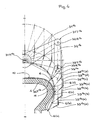
- This one is coated with rubber 10 (see figure 7 ), for example a layer of rubber butyl rubber gum, and a layer of gum ensuring the coating of the carcass son.
- the rubber 10 covering the core 1 allows to retain a wire 4 on the core 1 as it is removed, by a gluing effect.
- the core 1 is rotated by any suitable device, not shown.
- the actual laying members essentially comprise a rocker arm system 3 1a on the one hand, and presser devices 2 G and 2 D the other.
- the convention used is to designate similar members by the same main reference, for example "3" for the swingarm system, and to mark the specific membership of an embodiment or a variant by a number placed in superscript, for example " 1a " for the first embodiment (using a cascade of three oscillating arms), in its variant "a”.
- a reference without a specific mark refers to an organ that is always the same in the different variants or must be understood as denoting all the variants of all the embodiments.
- the oscillating arm system 3 1a comprises three functional oscillating arms 31 1a, 32 1a, 33 1a arranged in cascade and an auxiliary arm 34 1a.
- This arrangement with three functional oscillating arms makes it easy to move the guide member from one bead to the other, and thus to obtain, in conjunction with the pressing devices 2 and G 2 D, an action of the apparatus one bead to another.
- An eyelet 6 constitutes in all the examples described here the materialization of the guide member of the wire 4 (without this being limiting). The eyecup is always mounted on the last swingarm.
- the swingarm system 3 fulfills the function performed by the chain system in the application for EP 0 580 055 supra, and the pressing devices 2 G 2 and D are appropriately positioned to act as described in the application of EP 0 580 055 supra.
- the oscillating arm system 31a is mounted on a plate 30a , and is described to the eyepiece 6a a movement flying over the core 1, and even bypassing it in many embodiments.
- the oscillating arm system 3 makes the eyecup 6 move in a plane.
- the eyecup 6 is flared: it forms a funnel with a large opening 61 on the side of the arrival of the wire 4, and a smaller orifice 62 on the output side of the wire 4 (see also FIG. figure 3 ). It is the small orifice 62 which describes a movement in said plane of movement of the guide member.
- the eyecup can be oriented so as to approximate the average orientation of the wire at the exit of the eyecup.
- the plate 30 1a comprises a 3D oscillating shaft 1a (see also 3D to Figures 10 and 11 ) Motorizing the trailing arm system, the geometric axis of said oscillating shaft 3D 1a being located radially outside the core 1. In other words, the geometric axis of said oscillating shaft 3D 1a is situated beyond the core surface 1 , without its extension meeting the core 1. Said 3D oscillating shaft 1a does not perform a continuous rotation, but oscillates within the limits of an arc less than 360 °, the precise value depending on the exact constitution of the arm system oscillating 3 and the intended application.
- the entire swingarm system 3 itself is quite compact. All the installation members, namely the oscillating arm system 3 and the pressing devices 2, including the motor and the drive mechanism, form a subset that can easily be presented to the core appropriately, and can be retracted for example to present to the core of other devices used for the manufacture of a tire or for the evacuation of the core to other tire manufacturing stations.
- a base arm (or first arm) 31 1a ( figure 1 ) is mounted on the 3D oscillating shaft 1a by a center of rotation 31R 1a .
- the first arm 31 1a comprises a transport head 31T 1a at the end opposite the center of rotation 31R 1a .
- a second arm 32 1a articulated by a center of rotation 32R 1a of the second arm, is mounted on the transport head 31T 1a of the first arm 31 1a .
- This second arm 32 1a comprises a transport head 32T 1a .
- a parallelogram is formed by means of an auxiliary arm 34 1a , mounted oscillating about on an oscillating shaft 34D 1a by its center of rotation 34R 1a .
- the center of rotation 34R 1a is located radially outside the surface of the core 1, and radially between the latter and the center of rotation 31R 1a of the first arm 31 1a .
- the auxiliary arm 34 1a comprises a transport head 34T 1a articulated on the second arm 32 1a which comprises for this purpose an intermediate center of rotation 32I 1a located between the center of rotation 32R 1a and the transport head 32T 1a of said second arm 32 1a .
- the singular points that are the centers of rotation 31R 1a , 34R 1a and transport heads 31T 1a , 34T 1a form a parallelogram.
- these points are exactly aligned with the passage of the median position in the median plane, defined by the axis MM joining the centers of rotation 31R 1a , 34R 1a and the geometric axis of the 3D shaft (as well as by the geometric axis of the shaft 34D 1a which is of course parallel to the previous).
- the eyepiece 6 describes a movement whose path is symmetrical with respect to this median plane, and it reaches the vicinity of each of the bead zones defined on the core 1, in a perfectly symmetrical movement, even in its control. .
- the apparatus comprises a third arm 33 1a , articulated by its center of rotation 33R 1a on the transport head 32T 1a of the second arm 32 1a .
- This third arm 33 1a comprises a transport head LP 1a , on which is mounted directly the eyecup 6.
- the control means of the relative position of the third arm 33 1a relative to the second arm 32 1a not shown in figure 1 not to overload the drawing.
- a motor 35 controls the movement of all the arms 31 1a, 32 1a, 33 1a, 34 1a, preferably by motorization of the two shafts 1a and 3D 34D 1a, as explained in detail by means of Figures 10 and 11 .
- the motor 1a rotates a plate 70.
- An axis 71 is embedded in the plate 70 in a predetermined eccentric position.
- the shaft 71 supports a roller 72.
- a carriage 73 is translated on slides 74 arranged on the housing of the plate 30 1a .
- the carriage 73 comprises a rectilinear light 75, oriented perpendicularly to the direction of translation of the carriage 73 on the slideways 74.
- a chain (with tensioner) 76 is mounted on two identical pinions 77, and connected at its ends to the carriage 73.
- the pinions identical 77 are fixed one on the 3D shaft and the other on the shaft 34D.
- the roller 72 performs a circular motion 70R at a constant speed. In doing so, the roller 72 ascends and descends into the light 75, and translates the carriage 73, thus transforming a constant speed rotational movement into reciprocating and linear motion, the speed of which varies sinusoidally.
- this alternating linear motion is transformed on the 3D and 34D shafts, in oscillation scanning an arc less than 360 °.
- the amplitude of the oscillation can be adjusted by adjusting the radius at which the axis 71, therefore the roller 72) is mounted eccentrically on the plate 70.
- a wire 4 is delivered by a coil (not shown) and is then threaded onto a feed device 5 1a to bring and present the wire 4 correctly to the laying members.
- the feed device 5a comprises means ensuring the control of the tension of the thread 4, and if necessary the necessary compensation between the delivery members 31a and the spool, because the thread is called by said setting members at a cyclically variable speed, which can even be negative.
- the wire 4 is threaded into a first ring 51 1a disposed at some distance from the plane of movement, in which the eyelet 6 performs its cyclic movement.
- the ring 51 1a is disposed centrally with respect to the core 1.
- the wire 4 is then threaded into a ring 52 attached to the second arm 32 1a .
- the presser 2 D which comprises a fork 21 D and a hammer 22 D , both movable between a retracted position, in R (position away from the core 1), and an advanced position, in A. sees in ghost sight the hammer in advanced position.
- the convention used is to designate each member of the pressers by a main reference, for example "21" for the fork, and to mark the specific membership of the presser on one side, the side left or the right side at the figure 1 , respectively by the letter “ G " or " D " placed in superscript.
- a reference without a specific mark generically refers to one or the other of the pressers or to their organs.
- both the fork 21 and the hammer 22 have the appearance of parallel blades.
- the fork 21 is, relative to the hammer, always arranged radially on the side of the axis of rotation of the core 1.
- the fork 21 has a head 210 in "V", to take and center the wire 4. During the phase the plane formed by the "V” is arranged perpendicular to the wire 4.
- the blade forming the fork 21 is oriented tangentially to a circle concentric with the core 1.
- the fork 21 also includes an obvious 211 whose role will appear below.
- the fork 21 is intended to carry the wire 4 against the core 1.
- its advance towards the core 1 is triggered when the eyecup 6 has brought the wire 4 to one end of the movement in va-and- comes, ie when the device is substantially in the configuration of the figure 4 .
- the fork 21 is stopped when it anchored the thread in the rubber coating the core 1. Said fork 21 therefore allows to press the wire 4 with sufficient force to adhere properly to the desired location.
- the continued movement of the oscillating arm system 3 causes the formation of a loop around the tip 212, which initiates the removal of a new arch 40 on the core 1 (see figure 1 ).
- the passage of the eyecup 6 beyond the fork 21 in the return phase is allowed by the 211 obviously, although the fork 21 is pressed against the core 1 in this phase of manufacture.
- the size of the loop is a function of the size of the tip 212.
- the hammer 22 intervenes after the fork 21 and after the so-called return phase of the eyelet 6.
- the hammer 22 presses the wire 4 to a slightly higher radial position. Preferably, it still holds the wire 4 while retracting the fork 21. Maintaining the hammer while the fork retracts helps to prevent the fork 21 from taking with it the loop of wire 4 which has formed around one of its points 212, and that even if it is glued on the rubber, could tend to remain attached to the fork.
- the anchoring of the wire 4 in the bead is perfectly reliable.
- the tilting in the advanced position, and the return to the retracted position, both for the fork 21 and for the hammer 22, are controlled in synchronism with the oscillating arm system 31a , by any suitable device (movement reversal).
- the 3D shaft by a suitable mechanical transmission, for example by belt or cable or by electrical synchronization between several motors).
- a device or an equivalent device is simply shown schematically by an arrow, and designated by the reference 2, it being understood that this refers generally to a device with two actuators such as a fork and a hammer, intervening in sequence on the wire 4.
- the arm system 3 1b further comprises three functional arms 31 1b , 32 1b , 33 1b arranged in cascade, and said control means also allow, in conjunction with pressing devices, an action of the device from one bead to another.
- a base arm (or first arm) 31 1b is mounted on a 3D oscillating shaft 1b by a center of rotation 31R 1b .
- the first arm 31 1b comprises a transport head 31T 1b at the end opposite the center of rotation 31R 1b .
- a second arm 32 1b articulated by a center of rotation 32R 1b of the second arm, is mounted on the transport head 31T 1b of the first arm 31 1b .
- This second arm 32 1b comprises a transport head 32T 1b .
- the apparatus comprises a third arm 33 1b articulated by its center of rotation 33R 1b on the transport head 32T 1b of the second arm 32 1b .
- This third arm 33 1b comprises a transport head LP 1b , on which is directly mounted the eyelet 6.
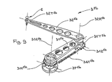
- the driving pulley 311 1b centered on the center of rotation 31R 1b of said first arm.
- the driving pulley 311 1b is integral with a flange 37 1b fixedly mounted on said platen (not shown in FIG. figure 3 ).
- a driven pulley 312 1b is integral (that is to say without possible relative rotation) of the second arm 32 1b .
- a toothed belt 361 1b connects said driving pulley and driven pulley.
- the diameters of the driving pulley and driven pulley are identical so that, during its movement, the second arm 32 1b always remains parallel to itself.
- the pulleys used are notched pulleys.
- the belts, also notched work without relative sliding relative to the pulleys on which they are mounted.
- the terms "pulley” and “belt” encompass all equivalent systems to control relative positions without slippage.
- the flange 37 1b is fixed in space, but more generally, it is important that its angular position is controlled independently of the oscillation control of said first arm. For example, it is possible to introduce a degree of freedom between the plate and the flange 37 1b , and to control the relative position of said puddle 37 1b with respect to the plate, in order to act selectively on the spatial position of the driving pulley 311 1b so as to for example, adapting the movement executed by the eyecup 6 to shapes of different sizes.
- the means for controlling the relative position of the third arm 33 1b relative to the second arm 32 1b essentially comprise a driving pulley 321 1b centered on the center of rotation 32R 1b of said second arm 32 1b , integral (no relative rotation possible) of the first arm 31 1b , and they comprise a driven pulley 322 1b integral (likewise, no possible relative rotation) of said third arm 33 1b .
- a toothed belt 362 1b connects said driving pulley and driven pulley.
- the diameters of the driving pulley and driven pulley are different, their respective values being calculated so that the transport end LP 1b , during its movement, reaches the zone of the core 1 near the bead (see figure 4 ), without the second arm 32 1b comes to hit the flank 11 of the core 1.
- the figure 4 shows the eyecup 6 in the position 6 (a) imposed by the apparatus described above, at one end of the reciprocating movement of the functional oscillating arms 31 1b , 32 1b , 33 1b .
- the corresponding configuration taken by the second and third arms of the apparatus is shown at 32b (a) and 33b (b) respectively.
- Different other positions and configurations are designated by the marks (b), (c), (d).
- the driving pulley 321 1b could also be mounted free with respect to the first arm 31 1b , and driven by a belt wound on the one hand on a pulley secured to said driving pulley 321 1b and on the other hand wound on another pulley (not shown) concentric with the 3D geometric axis 1b and motorized independently of both the movement of the first arm and the movement of the pulley 311 1b .
- This provides more latitude to control relative movement of the third arm relative to the second arm.
- the figure 5 illustrates an equivalent control, mounted on the swing arm system 3 1a of the figure 1 .
- a third pulley 321 1a centered on the intermediate center of rotation 32I 1a of said second arm 32 1a , integral (no relative rotation possible) of the intermediate arm 34 1a , and a fourth pulley 322 1a integral (likewise, no rotation relative possible) of the said third arm 33 1a .
- a toothed belt 362 1a connects said driving pulley and driven pulley.
- the diameters of the driving pulley and driven pulley are different, their respective values being calculated so that the transport end LP 1a , during its movement, reaches the zone of the core 1 near the bead (see figure 4 ), without the second arm 32 1a not hit the flank 11 of the core 1.
- the previous remark on another possibility of controlling the relative movement of the third arm relative to the second also applies to this variant.
- the arm system 31a is substantially in the same configuration as in the figure 1 .
- the second arm 32 1a is on one side of the first arm 31 1a and intermediate arm 34 1a (and on one side of the median plane defined by the axis MM and by the geometric axis of the 3D tree 1a ) and remains on this side during the portion of the movement during which the eyecup 6 overflies half of the core 1 located on one side of said median plane.
- the second arm 32 1a is made to pass from the other of the median plane, and doing so on the other side of the first arm 31 1a and intermediate arm 34 1a .
- the intermediate arm 34 1a passes over the first arm 31 1a . It is therefore appropriate for the arms to be correctly superimposed so that this movement is possible. This is the role of the spacers 381 1a and 382 1a . This remark is, of course, of general importance.
- the oscillating arms articulated to each other, in so far as they perform a symmetrical movement in its path relative to a median plane, must be judiciously superimposed on each other to allow all the desired arm crossings.
- the arm system 31c further comprises three functional arms 31c , 32c , 33c arranged in cascade, and said control also makes it possible, in conjunction with pressing devices, for an action of apparatus from one bead to another.
- the first arm 31c comprises a transport head 31T 1c .
- a second arm 32 1c articulated by a center of rotation 32R 1c of the second arm, is mounted on the transport head 31T 1c of the first arm 31 1c .
- This second arm 32 1c comprises a transport head 32T 1c .
- the apparatus comprises a third arm 33 1c , articulated by its center rotating 33R 1c on the transport head 32T 1c of the second arm 32 1c .
- This third arm 33 1c comprises a LP transport head 1c , on which is directly mounted the eyelet 6.
- a cam 381 1c is machined in the transport head 31T 1c of the first arm 31 1c .
- the cam comprises a neutral section 381N 1c machined at a constant mean radius, a final control section 381A 1c with increasing radius, for controlling the relative movement of the third arm 33c on one side of the core, and a final control section 381B. 1c decreasing radius, to control the relative movement of the third arm 33 1c on the other side of the core.
- a toothed wheel 322 1c is mounted on the center of rotation 33R 1c of the third arm 33 1c , and is integral (no possible relative rotation) of said third arm 33 1c .
- a rod 383 1c slides in a guide 384 1c integral with the second arm 32 1c .
- the rod 383 1c is thus guided in sliding relative to the second arm 32 1c .
- the rod 383 1c carries on one side a cam follower 382 1c cooperating with said cam 381 1c .
- the rod 383 1c comprises a rack 385 1c which is engaged on said toothed wheel 322 1c .
- the profile of the cam in the final control sections 381A 1c and 381B 1c is chosen so that the eyecup 6 mounted on the LP transport end 1c of the third arm 33c during the movement of said third arm 33c reaches the zone of core 1 near the bead (see position 6a of the figure 7 ), without the second arm 32 1b comes to hit the flank 11 of the core 1.
- the figure 7 shows the eyecup 6 in the position 6 (a ') imposed by the cam apparatus described above, at one end of the reciprocating movement of the functional swing arms 31c , 32c , 33c .
- the corresponding configuration taken by the second and third arms of the apparatus is shown at 32c (a ') and 33c (a') respectively.
- Various other positions and configurations are designated by the marks (b '), (c'), (d '). Comparing the figures 4 and 7 we see that if the positions noted (a) and (a ') are identical, the positions noted (b'), (c ') and (d') at the figure 7 differ somewhat from positions (b), (c) and (d) to figure 4 . Note the much larger guard at the side 11 preserved and allowed by the cam control.
- the oscillating arm system 32a comprises two functional oscillating arms 31 2a and 32 2a in cascade. It is designed for action of a bead with a shoulder, for example for the manufacture of a half-carcass. It is known that the carcass of a radial tire may not be continuous from one bead to the other, but may be interrupted somewhere under the tread, the belt reinforcement ensuring the transmission of forces between the half carcasses. The carcass reinforcement must be placed between the bead and a shoulder.
- the swing arm system 32a takes up the parallelogram principle of the swing arm system 31a , except that of course there is no third arm.
- a plate 2a supports a control motor 2a .
- the control motor 35 2a actuates 3D shafts 2a and 34D 2a whose geometrical axis of rotation is included in a median plane M 2a -M 2a .
- the control motor 35 2a also actuates the pressing devices 2 and G 2 D, the latter being of the same type as those whose form is described in more detail in figure 2 .
- the spacing of the presser devices 2 G and D 2 with respect to the median plane M 2a -M 2a can be adjusted by the knobs 23 and 24 2a 2a.
- a base arm (or first arm) 31 2a is mounted on the 3D oscillating shaft 2a by its center of rotation 31R 2a . Taking as a reference point the center C of the radial section of the core 1, the center of rotation 34R 2a is located outside the surface of the core 1.
- the first arm 31 2a comprises a transport head 31T 2a .
- a second arm 32 2a articulated by a center of rotation 32R 2a of the second arm, is mounted on the transport head 31T 2a of the first arm 31 2a .
- This second arm 32 2a comprises a transport head 32T 2a .
- a parallelogram is formed in this example by means of an auxiliary arm 34 2a mounted oscillating about the oscillating shaft 34D 2a through its center. rotation 34R 2a .
- the center of rotation 34R 2a is located outside the surface of the core 1, between the latter and the center of rotation 31R 2a of the first arm 31 2a .
- the auxiliary arm 34 2a comprises a transport head 34T 2a , articulated on the second arm 32 2a which comprises for this purpose an intermediate center of rotation 32I 2a located between the center of rotation 32R 2a and the transport head 32T 2a of said second arm 32 2a .
- the transport head 32T 2a of the second arm 32 2a directly supports the eyecup 6.
- the movement of the eyecup 6 is represented by the center line 63 2a .
- An apparatus with two functional oscillating arms, could equally well be used for an action of a bead up to any point under the tread, including up to the opposite shoulder, with a certain degree of overlap of the half-carcasses on each other.
- FIG 9 a variant comprising a swingarm system 32b different from that described for the system of the figure 8 essentially by the means for controlling the movement of the second arm 32 2b relative to the base arm (or first arm) 31 2b .
- this variant comprises a drive gear 311 2b centered on the center of rotation 31R 2b of said first arm.
- a base arm (or first arm) 31 2b is mounted on an oscillating shaft by its center of rotation 31R 2b .
- the first arm 31 2b comprises a transport head 31T 2b at the end opposite the center of rotation 31R 2b .
- a second arm 32 2b articulated by a center of rotation 32R 2b of the second arm, is mounted on the transport head 31T 2b of the first arm 31 2b .
- This second arm 32 2b comprises a transport head 32T 2b on which is directly mounted the eyelet 6.
- the driving gear 311 2b is integral with a flange 37 2b fixedly mounted on a plate (not shown in FIG. figure 9 ).
- a driven gear 312 2b is integral (that is to say without possible relative rotation) of the second arm 32 2b .
- a chain 361 2b connects said first and second gears.
- the diameters of the first and second pinions are identical so that, during its movement, the second arm 32 2b always remains parallel to itself.
- the arm system 32b can substitute for the arm system 32a of the figure 8 .
- the eyepiece 6 in all variants, is animated by a cyclic movement in a plane, referred to above as "eyepiece movement plane".
- the pre-coated surface of the core 1 determines the overall geometry of the laying surface of the reinforcing wire 4.
- the core 1 is rotated about its axis while the eyecup 6 goes back and forth. in the eyepiece movement plane.
- the movement of the core 1 is in synchronism with the movement back and forth of the eyepiece.
- the actual trajectory of the hoops 40 of the yarn 4 is therefore both a function of the relative position between the eyepiece movement plane and the core, and is a function of the relative movement between the core 1 and the comings and goings of the Eyecup 6.
- the trajectory of the arch 40 is substantially radial because it describes the realization of a carcass (or a half-carcass) for a radial tire, of course without this being limiting.
- Another example is given in a third embodiment, illustrated in FIG. figure 12 where the trajectory of the arch 40 3a is not radial, but forms a typical angle of the belt reinforcements (of the order of 15 ° to 30 °).
- the base arm 31 3a functional, adapted for example to the realization of reinforcements in the belt of a tire. It is adapted for example to a shoulder to shoulder action, to achieve belt reinforcements.
- the base arm 31 3a is mounted on a 3D oscillating shaft 3a by its center of rotation 31R 3a .
- the base arm 31 3a comprises a transport head 31T 3a to which an eyelet 6 is directly fixed.
- the plan of removal in which the eyelet 6 describes its reciprocating motion forms an angle of the order of 20 ° relative to a plane perpendicular to the axis of rotation of the core 1, according to the usual conventions for measure the angles in the field of the tire.
- the pressing devices 2 G and 2 D act in the same plane of deposition.
- the wire 4 is fed by the hollow center 51 3a of the 3D oscillation shaft 3a , and a high-capacity compensation system 52 3a is installed upstream.
- An advantage of the invention is that the apparatus thus implementing the basic method already known is mechanically simple and light, and that this device imposes at most only simple adjustments to implement to adapt to all the variants of the tire reinforcements to be executed, covering the widest range of tires possible.
- the swing arm system has few overhangs, little inertia and is suitable for high operating speeds.
- a carcass reinforcement can be made in several (n) laying passes, each pass covering the entire core.
- the radial arches inside a pass being placed in a pitch P, the position on the core 1 of the hoops 40 laid during n successive passes can then have a circumferential phase shift corresponding to P / n.
- the skilled person can also glimpse multiple ways to use the invention, depending on the architecture of the tire he wants to obtain.
- An advantage of the present invention is that it makes it possible to circumvent the shape in many cases of application, even if the trajectory of the hoops forms an angle very far from 90 ° (for example of the order of 20 °). Even in this case, it is still possible to successively reach two points of the shape each taken in the area corresponding to a bead of the tire, without the risk of striking the shape.
Abstract
Description
La présente invention concerne la fabrication des pneumatiques. Plus précisément, elle se rapporte à la mise en place de fils pour constituer un renforcement du pneumatique. Plus particulièrement, elle propose des moyens aptes à fabriquer un tel renforcement sur une forme proche ou identique de la forme de la cavité interne du pneumatique, c'est à dire une forme sensiblement toroïdale, supportant l'ébauche de pneumatique pendant sa fabrication.The present invention relates to the manufacture of tires. More specifically, it relates to the establishment of son to provide a strengthening of the tire. More particularly, it proposes means capable of manufacturing such a reinforcement on a near or identical shape of the shape of the internal cavity of the tire, that is to say a substantially toroidal shape, supporting the tire blank during its manufacture.
Dans ce domaine technique, on connaît déjà des procédés et appareils qui permettent d'intégrer la fabrication des renforcements de pneumatique à l'assemblage du pneumatique lui-même. Cela signifie que, plutôt que de recourir à des produits semi-finis, comme des nappes de renforcement, on réalise un ou des renforcements in situ, au moment où l'on fabrique le pneumatique, et à partir d'une seule bobine de fil. On connaît par exemple l'appareil décrit dans la demande
L'objectif de la présente invention est de proposer des variantes d'appareillage pour poser un fil de renforcement sur un noyau sensiblement de la même façon.The object of the present invention is to provide alternative equipment for laying a reinforcing wire on a core substantially in the same way.
L'invention propose un appareil de fabrication d'un renforcement pour pneumatique selon la revendication 1, ledit appareil étant destiné à fabriquer un renforcement constitué à partir d'un fil délivré en continu et à la demande par un distributeur approprié, ledit appareil étant destiné à être utilisé en coopération avec une forme sensiblement toroïdale sur lequel on construit progressivement ledit renforcement en déposant des arceaux dudit fil selon une trajectoire souhaitée pour ledit fil à la surface de ladite forme,
ledit appareil comprenant :
- un organe de guidage dans lequel le fil peut coulisser librement,
- des moyens de déplacement dudit organe de guidage selon un mouvement cyclique, en va-et-vient, pour amener en cycles successifs ledit organe de guidage au voisinage de chacune des extrémités souhaitées pour le fil dans ladite trajectoire,
- des presseurs proches de chaque extrémité de ladite trajectoire, pour appliquer le fil sur la forme auxdites extrémités,
- le moyen de déplacement comporte au moins un bras de base, ledit bras de base comportant un centre de rotation et une tête de transport, et des moyens de commande pour conférer audit bras de base un mouvement d'oscillation autour dudit centre de rotation, l'appareil étant agencé pour que la tête de transport dudit bras de base transporte directement ou indirectement l'organe de guidage d'une extrémité à l'autre de ladite trajectoire,
- l'axe géométrique dudit centre de rotation est, en position de travail, entièrement à l'extérieur de la forme.
said apparatus comprising:
- a guide member in which the wire can slide freely,
- means for moving said guide member cyclically, reciprocatingly, to bring successive cycles said guide member adjacent each of the desired ends for the wire in said path,
- squeezers near each end of said path, for applying the wire to the shape at said ends,
- the moving means comprises at least one base arm, said base arm having a center of rotation and a transport head, and control means for imparting to said base arm an oscillation movement about said center of rotation, apparatus being arranged so that the transport head of said base arm conveys directly or indirectly the guide member from one end to the other of said path,
- the geometric axis of said center of rotation is, in the working position, entirely outside the shape.
Des formes avantageuses de l'invention font l'objet des revendications dépendantes.Advantageous forms of the invention are the subject of the dependent claims.
Le lecteur est invité à consulter la demande de
C'est concernant les organes de dépose du fil, et plus précisément l'animation dudit organe de guidage dans lequel le fil peut coulisser librement (à savoir l'oeilleton), que l'invention apporte les principales différences. Autrement dit, le ou les systèmes à bras oscillants décrits ci-dessous sont conçus pour pouvoir prendre la place du système à chaîne décrit dans le brevet précité.It is with regard to the members for depositing the thread, and more specifically the animation of said guide member in which the thread can slide freely (namely the eyecup), that the invention provides the main differences. In other words, the swingarm system (s) described below are designed to be able to take the place of the chain system described in the aforementioned patent.
Avant d'aborder en détails la description de ces nouveaux moyens d'animation de l'organe de guidage du fil, rappelons quelques points utiles.Before discussing in detail the description of these new means of animation of the yarn guiding member, let us recall some useful points.
Notons tout d'abord que, comme dans le brevet cité, le terme "fil" doit bien entendu être compris dans un sens tout à fait général, englobant un monofilament, un multifilament, un assemblage comme par exemple un câble ou un retors, ou un petit nombre de câbles ou retors groupés, et ceci quelle que soit la nature du matériau, et que le "fil" soit pré revêtu de caoutchouc ou non. Dans le présent mémoire, on emploie le terme "arceau" pour désigner un tronçon de fil allant d'un point singulier à un autre dans l'armature de renforcement. L'ensemble de ces arceaux disposés sur tout le pourtour du pneumatique forme le renforcement proprement dit. Un arceau au sens défini ici peut faire partie d'une carcasse, ou d'un renfort de sommet, ou de tout autre type de renfort. Ces arceaux peuvent être individualisés par une coupe du fil en cours de pose, ou tous reliés entre eux dans le renforcement final, par exemple par des boucles.Let us first note that, as in the cited patent, the term "wire" must of course be understood in a very general sense, including a monofilament, a multifilament, an assembly such as a cable or a twist, or a small number of cables or twisted bundles, and this regardless of the nature of the material, and that the "wire" is pre-coated with rubber or not. In this specification, the term "hoop" is used to refer to a stretch of wire from one point singular to another in the reinforcement frame. All these hoops arranged around the entire periphery of the tire forms the reinforcement itself. A hoop in the sense defined herein may be part of a carcass, or a vertex reinforcement, or any other type of reinforcement. These arches can be individualized by cutting the wire during laying, or all interconnected in the final reinforcement, for example by loops.
Fondamentalement, l'invention traite de la dépose en continu d'un fil de renforcement, dans une configuration aussi proche que possible de la configuration dans le produit final. Le fil étant délivré à la demande par un distributeur approprié comportant par exemple une bobine de fil et le cas échéant un dispositif de contrôle de la tension du fil extrait de la bobine, l'appareil de fabrication d'un renfort à partir d'un seul fil coopère avec une forme (noyau rigide ou une membrane armée) sur laquelle on fabrique le pneumatique. Il importe peu que le renforcement soit, pour être complet, fabriqué en plusieurs passes successives des organes de pose décrits, avec coupe du fil ou non entre deux passes.Basically, the invention deals with the continuous removal of a reinforcement yarn, in a configuration as close as possible to the configuration in the final product. The wire being delivered on demand by a suitable distributor comprising, for example, a spool of thread and, if appropriate, a device for controlling the tension of the thread extracted from the spool, the apparatus for manufacturing a reinforcement from a spool. single wire cooperates with a form (rigid core or an armed membrane) on which the tire is manufactured. It matters little that the reinforcement is, to be complete, made in several successive passes of the laying members described, with wire cutting or not between two passes.
Lorsque l'on définit des positions, des directions ou des sens avec les mots "radialement, axialement, circonférentiellement", ou lorsque l'on parle de rayons, on prend pour repère le noyau sur lequel on fabrique le pneumatique, ou le pneumatique par lui-même, ce qui revient au même. L'axe géométrique de référence est l'axe de rotation de la forme.When defining positions, directions or directions with the words "radially, axially, circumferentially", or when speaking of spokes, we take as a reference the core on which the tire is manufactured, or the tire by himself, which amounts to the same thing. The reference geometric axis is the axis of rotation of the shape.
De même, comme déjà signalé dans le brevet précité, les organes de pose du fil décrits ici permettent aussi de réaliser un renforcement, par exemple un renforcement de carcasse, dans lequel le pas de pose du fil est variable. On entend par "pas de pose" la distance résultant de la somme de l'écart entre deux fils adjacents et le diamètre du fil. Il est bien connu que pour un renforcement de carcasse, l'écart entre fils varie selon le rayon auquel on le mesure. Il ne s'agit pas de cette variation dont il est question ici, mais bien d'un pas variable à un rayon donné. Il suffit pour cela de, sans changer la cadence de travail de l'organe de guidage, faire varier selon toute loi appropriée la vitesse de rotation de la forme. On obtient ainsi un pneumatique dont les fils de renforcement de carcasse, par exemple pour une carcasse radiale, sont disposés selon un pas présentant une variation contrôlée pour une position radiale donnée.Likewise, as already mentioned in the aforementioned patent, the wire laying members described here also make it possible to carry out a reinforcement, for example a carcass reinforcement, in which the pitch of the wire is variable. The term "no laying" the distance resulting from the sum of the gap between two adjacent son and the diameter of the wire. It is well known that for a carcass reinforcement, the spacing between wires varies according to the radius at which it is measured. It is not a question of this variation of which we are speaking here, but of a variable step at a given radius. It suffices for this, without changing the working rate of the guide member, to vary in any appropriate law the speed of rotation of the form. This produces a tire whose carcass reinforcement son, for example for a radial carcass, are arranged in a pitch having a controlled variation for a given radial position.
Différents modes de réalisation de l'invention peuvent être envisagés. Dans la suite, on décrit trois principaux modes de réalisation. Le premier mode de réalisation utilise une cascade de trois bras oscillants fonctionnels. On donne en outre des variantes possibles pour ce premier mode de réalisation. On utilisera de préférence une cascade à trois bras oscillants fonctionnels pour la dépose d'arceaux de carcasse allant d'un bourrelet à l'autre bourrelet du pneumatique. Le deuxième mode de réalisation utilise une cascade de deux bras oscillants fonctionnels. On donne en outre une variante de réalisation pour ce deuxième mode de réalisation. On utilisera par exemple une cascade à deux bras oscillants fonctionnels pour la dépose d'arceaux de carcasse allant d'un bourrelet à une épaule du pneumatique. Le troisième mode de réalisation utilise un seul bras oscillant fonctionnel, ce qui suffit pour les déposes les plus simples à réaliser.Different embodiments of the invention may be envisaged. In the following, three main embodiments are described. The first embodiment uses a cascade of three functional swing arms. In addition, possible variants are given for this first mode of production. A cascade with three functional oscillating arms is preferably used for the removal of carcass hoops going from one bead to the other bead of the tire. The second embodiment uses a cascade of two functional swing arms. An embodiment variant is furthermore given for this second embodiment. For example, a cascade with two functional oscillating arms for the removal of carcass hoops going from a bead to a shoulder of the tire will be used. The third embodiment uses a single functional oscillating arm, which is sufficient for the simplest depositions to achieve.
Lorsque l'on utilise « n » bras oscillants fonctionnels agencés en cascade (n > 1), on conviendra d'appeler « nième bras » le bras oscillant fonctionnel sur lequel l'organe de guidage du fil est directement fixé, le bras de base étant toujours le « premier bras » oscillant. Les bras oscillant sont agencés en cascade de sorte que, en toute généralité, la tête de transport du bras oscillant « p » (avec p < n) transporte le centre de rotation du bras oscillant « p+1 ». C'est pourquoi on a précisé ci-dessus que la tête de transport porte l'organe de guidage du fil directement, ou bien seulement « indirectement » (c'est à dire par l'intermédiaire d'un ou de plusieurs autres bras oscillant fonctionnels). Dans tous les exemples décrits, l'axe géométrique du centre de rotation du premier bras oscillant est, en position de travail, entièrement à l'extérieur de la forme qu'il ne rencontre jamais, c'est à dire pas même par ses prolongements.When using "n" functional oscillating arms arranged in cascade (n> 1), it will be appropriate to call "n th arm" the functional oscillating arm on which the wire guiding member is directly fixed, the arm of base still being the oscillating "first arm". The oscillating arms are arranged in cascade so that, in general, the transport head of the swing arm "p" (with p <n) carries the center of rotation of the swing arm "p + 1". This is why it was stated above that the transport head carries the guide member of the wire directly, or only "indirectly" (ie via one or more other oscillating arms functional). In all the examples described, the geometric axis of the center of rotation of the first oscillating arm is, in the working position, entirely outside the shape that it never meets, ie not even by its extensions. .
L'appareil fait décrire à l'organe de guidage du fil un mouvement sensiblement compris dans un plan -le plan de mouvement- perpendiculairement à l'axe géométrique de rotation du bras de base. Sous un autre aspect de l'appareil selon l'invention, le bras de base, ou selon les variantes chacun des bras oscillant utilisés est d'allure plane, longiligne, et le bras de base oscille dans ce plan de mouvement, ou l'ensemble des bras oscillants se meuvent dans des plans parallèles et voisins, l'un d'eux étant très proche de ce plan de mouvement, voire pouvant être confondu avec ce plan de mouvement, selon la nature de l'organe de guidage utilisé.The apparatus causes the yarn guiding member to move substantially in a plane - the plane of motion - perpendicular to the geometric axis of rotation of the base arm. In another aspect of the apparatus according to the invention, the base arm, or according to the variants each of the oscillating arms used is planar, elongate, and the base arm oscillates in this plane of movement, or the all oscillating arms move in parallel and neighboring planes, one of them being very close to this plane of movement, or even be confused with this plane of movement, depending on the nature of the guiding member used.
La suite de la description permet de bien faire comprendre tous les aspects de l'invention, en s'appuyant sur les figures suivantes :
- La
figure 1 est une perspective schématique montrant un premier mode de réalisation d'un appareil selon l'invention ; - La
figure 2 est un détail d'un presseur de cet appareil ; - La
figure 3 illustre une première variante du premier mode de réalisation ; - La
figure 4 représente plus en détail une phase de fonctionnement de l'appareil selon le premier mode de réalisation ; - La
figure 5 illustre un détail du premier mode de réalisation non visible à lafigure 1 ; - La
figure 6 illustre une deuxième variante du premier mode de réalisation ; - La
figure 7 représente les stades successifs du fonctionnement de la deuxième variante du premier mode de réalisation ; - La
figure 8 est une coupe radiale montrant un deuxième mode de réalisation d'un appareil selon l'invention ; - La
figure 9 illustre une variante du deuxième mode de réalisation ; - La
figure 10 est une vue en élévation (coupe dans le plan défini à lafigure 1 par l'axe MM et l'axe géométrique de l'arbre 3D, aussi appelé « plan médian ») du mécanisme de commande utilisée dans le premier mode de réalisation illustré à lafigure 1 ; - La
figure 11 est une coupe selon AA à lafigure 10 ; - La
figure 12 est une perspective schématique montrant un troisième mode de réalisation d'un appareil selon l'invention.
- The
figure 1 is a schematic perspective showing a first embodiment of an apparatus according to the invention; - The
figure 2 is a detail of a presser of this apparatus; - The
figure 3 illustrates a first variant of the first embodiment; - The
figure 4 shows in greater detail a phase of operation of the apparatus according to the first embodiment; - The
figure 5 illustrates a detail of the first embodiment not visible to thefigure 1 ; - The
figure 6 illustrates a second variant of the first embodiment; - The
figure 7 represents the successive stages of operation of the second variant of the first embodiment; - The
figure 8 is a radial section showing a second embodiment of an apparatus according to the invention; - The
figure 9 illustrates a variant of the second embodiment; - The
figure 10 is an elevation view (section in the plane defined atfigure 1 by the axis MM and the geometric axis of the 3D shaft, also called the "median plane") of the control mechanism used in the first embodiment illustrated in FIG.figure 1 ; - The
figure 11 is a cut according to AA at thefigure 10 ; - The
figure 12 is a schematic perspective showing a third embodiment of an apparatus according to the invention.
A la
Les organes de pose proprement dits comportent essentiellement un système à bras oscillants 31a d'une part, et des dispositifs presseurs 2G et 2D d'autre part. En ce qui concerne les références aux figures, la convention utilisée est de désigner des organes similaires par la même référence principale, par exemple « 3 » pour le système à bras oscillants, et de marquer l'appartenance spécifique à un mode de réalisation ou à une variante par un nombre placé en exposant, par exemple « 1a » pour le premier mode de réalisation (utilisant une cascade de trois bras oscillants), dans sa variante « a ». Une référence sans marque spécifique renvoie à un organe toujours le même dans les différentes variantes ou doit être comprise comme désignant indifféremment toutes les variantes de tous les modes de réalisation.The actual laying members essentially comprise a rocker arm system 3 1a on the one hand, and presser devices 2 G and 2 D the other. As regards the references to the figures, the convention used is to designate similar members by the same main reference, for example "3" for the swingarm system, and to mark the specific membership of an embodiment or a variant by a number placed in superscript, for example " 1a " for the first embodiment (using a cascade of three oscillating arms), in its variant "a". A reference without a specific mark refers to an organ that is always the same in the different variants or must be understood as denoting all the variants of all the embodiments.
Dans le premier mode de réalisation montré à la
Le système à bras oscillants 31a est monté sur une platine 301a, et fait décrire à l'oeilleton 61a un mouvement survolant le noyau 1, et même le contournant dans beaucoup d'exemples de réalisation. Dans tous les cas de figure, le système à bras oscillants 3 fait parcourir à l'oeilleton 6 un mouvement dans un plan. L'oeilleton 6 est évasé : il forme un entonnoir avec une grande ouverture 61 du côté de l'arrivée du fil 4, et un plus petit orifice 62 du côté de la sortie du fil 4 (voir aussi la
La platine 301a comporte un arbre oscillant 3D1a (voir aussi 3D aux
L'ensemble du système à bras oscillants 3 lui-même est assez compact. L'ensemble des organes de pose, à savoir le système à bras oscillants 3 et les dispositifs presseurs 2, y compris le moteur et le mécanisme d'entraînement, forment un sous-ensemble pouvant facilement être présenté au noyau de façon appropriée, et pouvant être escamoté pour par exemple présenter au noyau d'autres dispositifs utilisés pour la fabrication d'un pneumatique ou pour l'évacuation du noyau vers d'autres postes de confection d'un pneumatique.The entire swingarm system 3 itself is quite compact. All the installation members, namely the oscillating arm system 3 and the pressing devices 2, including the motor and the drive mechanism, form a subset that can easily be presented to the core appropriately, and can be retracted for example to present to the core of other devices used for the manufacture of a tire or for the evacuation of the core to other tire manufacturing stations.
Un bras de base (ou premier bras) 311a (
Remarquons qu'il n'est pas nécessaire que les points singuliers que sont les centres de rotation 31R1a, 34R1a et les têtes de transport 31T1a, 34T1a forment un parallélogramme. De préférence, ces points sont exactement alignés au passage de la position médiane dans le plan médian, défini par l'axe MM joignant les centres de rotation 31R1a, 34R1a et par l'axe géométrique de l'arbre 3D (ainsi que par l'axe géométrique de l'arbre 34D1a qui est bien entendu parallèle au précédent). De la sorte, l'oeilleton 6 décrit un mouvement dont le tracé est symétrique par rapport à ce plan médian, et il atteint le voisinage de chacune des zones de bourrelet définies sur le noyau 1, dans un mouvement parfaitement symétrique, même dans sa commande. Ceci n'exclut pas bien entendu que les extrémités du mouvement de l'oeilleton ne soient pas en des points symétriques par rapport au plan médian, par exemple pour fabriquer un pneumatique dont la trajectoire des arceaux ne serait pas symétrique. Ce serait le cas pour fabriquer un pneumatique dont les diamètres au seat (terme usuel pour désigner le siège de montage) de chacun des bourrelets sont différents.Note that it is not necessary that the singular points that are the centers of
Enfin, l'appareil comporte un troisième bras 331a, articulé par son centre de rotation 33R1a sur la tête de transport 32T1a du deuxième bras 321a. Ce troisième bras 331a comporte une tête de transport 33T1a, sur laquelle est directement monté l'oeilleton 6. Dans la suite, à l'aide de la
Un moteur 351a commande le mouvement de l'ensemble des bras 311a, 321a, 331a, 341a, de préférence par motorisation des deux arbres 3D1a et 34D1a, comme expliqué en détail au moyen des
En supposant que le moteur 35 imprime à l'arbre de commande 350 un mouvement de rotation à vitesse constante, le galet 72 exécute un mouvement circulaire 70R à vitesse constante. Ce faisant, le galet 72 monte et descend dans la lumière 75, et translate le chariot 73, transformant ainsi un mouvement de rotation à vitesse constante en mouvement de va-et-vient, alternatif et linéaire, dont la vitesse varie sinusoïdalement. Par l'intermédiaire de la chaîne 76 et des pignons identiques 77, ce mouvement linéaire variant alternativement est transformé sur les arbres 3D et 34D, en oscillation balayant un arc inférieur à 360°. On peut régler l'amplitude de l'oscillation en réglant le rayon auquel l'axe 71, donc le galet 72) est monté de façon excentrée sur le plateau 70. A la loi de transformation d'un mouvement ainsi créée mécaniquement, on peut bien entendu superposer n'importe quelle loi de commande particulière pour la rotation du rotor du moteur 35.Assuming that the motor 35 imparts constant speed rotational movement to the control shaft 350, the
Revenons à l'explication de la
Ce fil 4 est enfilé sur un oeilleton 6. L'oeilleton 6 décrit un mouvement de va-et-vient d'un bourrelet à l'autre, ou plus précisément d'un endroit proche d'un bourrelet, à un endroit proche de l'autre bourrelet. Le cycle de base du fonctionnement des appareils selon l'invention comporte les étapes suivantes :
- le fil étant retenu contre la forme pendant un temps suffisant, déplacer l'oeilleton (organe de guidage) dans un plan de mouvement d'oeilleton jusqu'à une première extrémité,
- appliquer le fil sur la forme à cette première extrémité et l'y maintenir au moins un temps suffisant, au moyen d'un dispositif presseur,
- répéter la première étape en sens inverse jusqu'à une deuxième extrémité,
- appliquer le fil sur la forme à cette deuxième extrémité et l'y maintenir, au moyen d'un autre dispositif presseur,
- the wire being retained against the shape for a sufficient time, moving the eyelet (guide member) in a plane of eyecup movement to a first end,
- apply the wire to the shape at this first end and hold it there for at least a sufficient time, by means of a pressing device,
- repeat the first step in reverse to a second end,
- apply the yarn on the shape to this second end and hold it there, by means of another pressing device,
A la
Le lecteur est à nouveau invité à consulter la partie adéquate de la description de la demande de
On sait que la fourche 21 est destinée à emporter le fil 4 contre le noyau 1. A cette fin, son avance vers le noyau 1 est déclenchée lorsque l'oeilleton 6 a amené le fil 4 à une extrémité du mouvement en va-et-vient, c'est à dire lorsque l'appareil est sensiblement dans la configuration de la
Le marteau 22 intervient après la fourche 21 et après la phase dite de retour de l'oeilleton 6. Le marteau 22 appuie sur le fil 4 à une position radiale un peu plus élevée. De préférence, il retient encore le fil 4 pendant que l'on rétracte la fourche 21. Le maintien du marteau pendant que la fourche se rétracte aide à éviter que la fourche 21 n'emporte avec elle la boucle de fil 4 qui s'est formée autour d'une de ses pointes 212, et qui même si elle est collée sur le caoutchouc, pourrait avoir tendance à rester solidaire de la fourche. L'ancrage du fil 4 dans le bourrelet s'en trouve parfaitement fiabilisé.The
Bien entendu, le basculement en position avancée, et le retour en position reculée, aussi bien pour la fourche 21 que pour le marteau 22, sont commandés en synchronisme avec le système à bras oscillants 31a, par tout dispositif convenable (renvoi de mouvement de l'arbre 3D par une transmission mécanique appropriée, par exemple à courroies ou à câble ou par synchronisation électrique entre plusieurs moteurs). Dans la suite, un tel dispositif ou un dispositif équivalent est simplement schématisé par une flèche, et désigné par la référence 2, étant entendu que cela désigne en toute généralité un dispositif à deux actionneurs comme une fourche et un marteau, intervenant en séquence sur le fil 4.Of course, the tilting in the advanced position, and the return to the retracted position, both for the
A la
On voit une poulie menante 3111b centré sur le centre de rotation 31R1b dudit premier bras. La poulie menante 3111b est solidaire d'un flasque 371b monté fixe sur ladite platine (non représentée à la
Dans cet exemple, le flasque 371b est fixe dans l'espace, mais plus généralement, il importe que sa position angulaire soit contrôlée indépendamment de la commande d'oscillation dudit premier bras. On peut par exemple introduire un degré de liberté entre la platine et le flasque 371b, et commander la position relative dudit flaque 371b par rapport à la platine, pour agir sélectivement sur la position spatiale de la poulie menante 3111b afin de, par exemple, adapter le mouvement exécuté par l'oeilleton 6 à des formes de tailles différentes.In this example, the flange 37 1b is fixed in space, but more generally, it is important that its angular position is controlled independently of the oscillation control of said first arm. For example, it is possible to introduce a degree of freedom between the plate and the flange 37 1b , and to control the relative position of said puddle 37 1b with respect to the plate, in order to act selectively on the spatial position of the driving pulley 311 1b so as to for example, adapting the movement executed by the
Quant aux moyens de commande de la position relative du troisième bras 331b par rapport au deuxième bras 321b, ils comportent essentiellement une poulie menante 3211b centrée sur le centre de rotation 32R1b dudit deuxième bras 321b, solidaire (pas de rotation relative possible) du premier bras 311b, et ils comportent une poulie menée 3221b solidaire (de même, pas de rotation relative possible) dudit troisième bras 331b. Une courroie crantée 3621b relie lesdites poulie menante et poulie menée. Les diamètres des poulie menante et poulie menée sont différents, leurs valeurs respectives étant calculées pour que l'extrémité de transport 33T1b, pendant son mouvement, atteigne la zone du noyau 1 proche du bourrelet (voir
La
En variante, la poulie menante 3211b pourrait aussi être montée libre par rapport au premier bras 311b, et entraînée par une courroie enroulée d'une part sur une poulie solidaire de ladite poulie menante 3211b et d'autre part enroulée sur une autre poulie (non représentée) concentrique à l'axe géométrique 3D1b et motorisée indépendamment à la fois du mouvement du premier bras et du mouvement de la poulie 3111b. Cela offre plus de latitudes pour contrôler le mouvement relatif du troisième bras par rapport au deuxième.Alternatively, the driving pulley 321 1b could also be mounted free with respect to the
La
Soulignons un autre détail de réalisation qui est bien visible sur la
A l'aide
On voit un bras de base (ou premier bras) 311c et un deuxième bras 321c, la description du mouvement relatif entre le premier et le deuxième bras étant superflue car elle peut être identique à ce qui a été décrit pour le système à bras 31a ou 31b. Le premier bras 311c comporte une tête de transport 31T1c. Un deuxième bras 321c, articulé par un centre de rotation 32R1c du deuxième bras, est monté sur la tête de transport 31T1c du premier bras 311c. Ce deuxième bras 321c comporte une tête de transport 32T1c. Enfin, l'appareil comporte un troisième bras 331c, articulé par son centre de rotation 33R1c sur la tête de transport 32T1c du deuxième bras 321c. Ce troisième bras 331c comporte une tête de transport 33T1c, sur laquelle est directement monté l'oeilleton 6. Une came 3811c est usinée dans la tête de transport 31T1c du premier bras 311c. La came comporte un tronçon neutre 381N1c usiné à un rayon moyen constant, un tronçon de contrôle final 381A1c à rayon croissant, pour commander le mouvement relatif du troisième bras 331c d'un côté du noyau, et un tronçon de contrôle final 381B1c à rayon décroissant, pour commander le mouvement relatif du troisième bras 331c de l'autre côté du noyau. Une roue dentée 3221c est montée sur le centre de rotation 33R1c du troisième bras 331c, et est solidaire (pas de rotation relative possible) dudit troisième bras 331c. Une biellette 3831c coulisse dans un guide 3841c solidaire du deuxième bras 321c. La biellette 3831c est ainsi guidée en coulissement par rapport au deuxième bras 321c. La biellette 3831c porte d'un côté un suiveur de came 3821c coopérant avec ladite came 3811c. Du côté opposé au suiveur de came 3821c, la biellette 3831c comporte une crémaillère 3851c qui est engagée sur ladite roue dentée 3221c. Le profil de la came dans les tronçons de contrôle final 381A1c et 381B1c est choisi pour que l'oeilleton 6 monté sur l'extrémité de transport 33T1c du troisième bras 331c, pendant le mouvement dudit troisième bras 331c, atteigne la zone du noyau 1 proche du bourrelet (voir position 6a de la
La
Grâce à la commande par came, le mouvement relatif entre deuxième et troisième bras peut être ajusté aux besoins assez librement puisqu'il dépend essentiellement du profil de la came. On est ainsi libéré de la contrainte de proportionnalité au mouvement rotatif relatif entre le premier et le deuxième bras, spécifique de la commande par courroie décrite à l'aide des
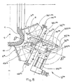
Dans un deuxième mode de réalisation, illustré aux
Un bras de base (ou premier bras) 312a est monté sur l'arbre oscillant 3D2a par son centre de rotation 31R2a. En prenant pour point de repère le centre C de la section radiale du noyau 1, le centre de rotation 34R2a est situé à l'extérieur de la surface du noyau 1. Le premier bras 312a comporte une tête de transport 31T2a. Un deuxième bras 322a, articulé par un centre de rotation 32R2a du deuxième bras, est monté sur la tête de transport 31T2a du premier bras 312a. Ce deuxième bras 322a comporte une tête de transport 32T2a. Afin de commander la position relative du deuxième bras 322a par rapport au premier bras 312a, on forme dans cet exemple un parallélogramme au moyen d'un bras auxiliaire 342a, monté oscillant autour sur l'arbre oscillant 34D2a par son centre de rotation 34R2a. En prenant pour point de repère le centre C de la section radiale du noyau 1, le centre de rotation 34R2a est situé à l'extérieur de la surface du noyau 1, entre celle-ci et le centre de rotation 31R2a du premier bras 312a. Le bras auxiliaire 342a comporte une tête de transport 34T2a, articulé sur le deuxième bras 322a qui comporte à cette fin un centre de rotation intermédiaire 32I2a situé entre le centre de rotation 32R2a et la tête de transport 32T2a dudit deuxième bras 322a. La tête de transport 32T2a du deuxième bras 322a supporte directement l'oeilleton 6. Le mouvement de l'oeilleton 6 est représentée par le trait d'axe 632a.A base arm (or first arm) 31 2a is mounted on the 3D oscillating shaft 2a by its center of rotation 31R 2a . Taking as a reference point the center C of the radial section of the
Un appareil selon ce principe, à deux bras oscillants fonctionnels, pourrait tout aussi bien être utilisé pour une action d'un bourrelet jusqu'à n'importe quel point sous la bande de roulement, y compris jusqu'à l'épaule opposée, avec un certain degré de chevauchement des demi-carcasses l'une sur l'autre.An apparatus according to this principle, with two functional oscillating arms, could equally well be used for an action of a bead up to any point under the tread, including up to the opposite shoulder, with a certain degree of overlap of the half-carcasses on each other.
A la
On voit un bras de base (ou premier bras) 312b est monté sur un arbre oscillant par son centre de rotation 31R2b. Le premier bras 312b comporte une tête de transport 31T2b à l'extrémité opposée au centre de rotation 31R2b. Un deuxième bras 322b, articulé par un centre de rotation 32R2b du deuxième bras, est monté sur la tête de transport 31T2b du premier bras 312b. Ce deuxième bras 322b comporte une tête de transport 32T2b sur laquelle est directement monté l'oeilleton 6. Le pignon menant 3112b est solidaire d'un flasque 372b monté fixe sur une platine (non représentée à la
Rappelons que l'oeilleton 6, dans toutes les variantes, est animé d'un mouvement cyclique dans un plan, appelé ci-dessus « plan de mouvement d'oeilleton ». Par ailleurs, la surface pré revêtue du noyau 1 détermine la géométrie globale de la surface de dépose du fil 4 de renforcement. En outre, le noyau 1 est entraîné en rotation autour de son axe pendant que l'oeilleton 6 effectue ses va-et-vient dans le plan de mouvement d'oeilleton. Bien entendu, le mouvement du noyau 1 est en synchronisme avec le mouvement de va-et-vient de l'oeilleton. La trajectoire réelle des arceaux 40 du fil 4 est donc à la fois fonction de la position relative entre le plan de mouvement d'oeilleton et le noyau, et est fonction du mouvement relatif entre le noyau 1 et le va-et-vient de l'oeilleton 6.Recall that the
Aux
Dans ce troisième mode de réalisation représenté à la
Pour réaliser une carcasse croisée dans les flancs, on peut éloigner le plan de mouvement d'oeilleton d'une orientation purement radiale, par inclinaison du support des organes de pose (comme la platine 30) autour d'un axe parallèle à l'axe de rotation du noyau 1. On peut bien entendu combiner ce réglage avec celui appliqué au paragraphe précédant illustrant la réalisation de renforts de ceinture. On peut encore, sans rien changer aux organes de l'appareil telle que décrite, entraîner le noyau à une vitesse assez élevée, par exemple 1/8 de tour pour un va-et-vient du système à bras 3, de sorte que l'on obtient un angle de pose du fil qui est fonction du rapport entre la vitesse de la chaîne et la vitesse du noyau (alors que dans tous les exemples précédents la vitesse du noyau 1 n'agissait que sur le seul pas de pose).To make a carcass crossed in the flanks, it is possible to move the eyepiece movement plane away from a purely radial orientation, by inclining the support of the positioning members (such as the plate 30) around an axis parallel to the axis of rotation of the
La remarque suivante explique une variante supplémentaire, que l'on peut appliquer à tous les modes de réalisation décrits ici, dans toutes leurs variantes. On peut animer le support des organes de pose (comme la platine 301a - voir
Un avantage de l'invention est que l'appareil mettant ainsi en oeuvre le procédé de base déjà connu est mécaniquement simple et léger, et que cet appareil n'impose au maximum que des réglages simples à mettre en oeuvre pour s'adapter à toutes les variantes des renforts pour pneumatique à exécuter, en couvrant la plus grande gamme de pneumatiques possible. Le système à bras oscillants présente peu de porte-à-faux, peu d'inertie et se prête bien à des cadences de fonctionnement élevées.An advantage of the invention is that the apparatus thus implementing the basic method already known is mechanically simple and light, and that this device imposes at most only simple adjustments to implement to adapt to all the variants of the tire reinforcements to be executed, covering the widest range of tires possible. The swing arm system has few overhangs, little inertia and is suitable for high operating speeds.
On peut réaliser un renfort de carcasse en plusieurs (n) passes de pose, chaque passe recouvrant tout le noyau. Les arceaux radiaux à l'intérieur d'une passe étant posés selon un pas P, la position sur le noyau 1 des arceaux 40 posés pendant n passes successives peut présenter alors un déphasage circonférentiel correspondant à P/n. L'homme de métier peut aussi entrevoir de multiples façons d'utiliser l'invention, selon l'architecture du pneumatique qu'il veut obtenir.A carcass reinforcement can be made in several (n) laying passes, each pass covering the entire core. The radial arches inside a pass being placed in a pitch P, the position on the
Signalons encore que, dans le cas de réalisation de demi-carcasses (voir
Un avantage de la présente invention est qu'elle permet de contourner la forme dans de nombreux cas d'application, y compris si la trajectoire des arceaux forme un angle très éloigné de 90° (par exemple de l'ordre de 20°). Même dans ce cas, on peut encore atteindre successivement deux points de la forme pris chacun dans la zone correspondant à un bourrelet du pneumatique, sans risquer d'heurter la forme.An advantage of the present invention is that it makes it possible to circumvent the shape in many cases of application, even if the trajectory of the hoops forms an angle very far from 90 ° (for example of the order of 20 °). Even in this case, it is still possible to successively reach two points of the shape each taken in the area corresponding to a bead of the tire, without the risk of striking the shape.
Claims (13)
- Device for manufacturing a reinforcement for a tyre, the said device being intended to manufacture a reinforcement made from a wire (4) fed continuously and on demand by an appropriate feeder, the said device being intended to be used in cooperation with a substantially toroidal form on which the said reinforcement is progressively constructed by depositing hoops of the said wire on a required trajectory for the said wire on the surface of the said form, the said device comprising:• a guide member (6) in which the wire may slide freely,• means of moving the said guide member in a cyclical motion, to and fro, to bring the said guide member in successive cycles to the vicinity of each of the ends required for the wire in the said trajectory,• pressers (2) close to each end of the said trajectory, to press the wire (4) onto the form at the said ends,• the movement means comprises at least one basic arm (31), the said basic arm comprising a centre of rotation (31R) and a transport head (31T), and control means for conferring on the said basic arm an oscillating movement about the said centre of rotation, the device being arranged so that the transport head (31T) of the said basic arm directly or indirectly transports the guide member from one end to the other of the said trajectory,characterized in that the geometric axis of the said centre of rotation is, in the working position, entirely outside the form.
- Device according to Claim 1, in which the transport head (31T) of the basic arm (31) directly supports the said guide member (6).
- Device according to Claim 1, comprising a second arm (32), articulated by a centre of rotation (32R) of the second arm, the said centre of rotation of the second arm being mounted on the said transport head (31T) of the said basic arm, the said second arm having a transport head (32T) to directly or indirectly transport the guide member from one end to the other of the said trajectory, and comprising means for controlling the relative position of the second arm relative to the said basic arm.
- Device according to Claim 3, in which the said means of controlling the relative position of the second arm (32) relative to the basic arm (31) essentially comprise a drive pulley (311) centred on the centre of rotation of the said basic arm, the angular position of the said drive pulley being controlled independently of the oscillation control of the said basic arm, and comprising a driven pulley (312) fixedly attached to the said second arm, a notched belt (361) connecting the said pulleys.
- Device according to Claim 4, in which the said drive pulley (311) is fixed in space.
- Device according to Claim 1, comprising a second oscillating arm (32), the centre of rotation (32R) of the second arm being mounted on the transport end (31T) of the said basic arm (31), the said second arm having a transport head (32T) for directly or indirectly transporting the guide member from one end to the other of the said trajectory, and comprising an auxiliary arm (34) oscillating about a centre of rotation (34R), the geometric axis of rotation of the said centre of rotation of the auxiliary arm being situated entirely outside the surface of the form, between the latter and the geometric axis of rotation of the said basic arm, the said auxiliary arm having a transport head (34T), the said second arm having an intermediate centre of rotation (321) between the centre of rotation (32R) of the second arm and the transport head (32T) of the said second arm, the said intermediate centre of rotation being articulated on the transport head (34T) of the said auxiliary arm.
- Device according to Claim 3 or 6, in which the transport head (32T) of the second arm directly supports the said guide member (6).
- Device according to one of Claims 3 to 6, comprising a third oscillating arm (33), articulated by its centre of rotation (33R) on the transport head (32T) of the second arm, the said third arm having a transport head (33T) for directly or indirectly transporting the guide member from one end to the other of the said trajectory, and comprising means of controlling the relative position of the third arm relative to the second arm.
- Device according to Claim 8, in which the transport head (33T) of the third arm directly supports the said guide member (6).
- Device according to Claim 8 and 4 or 9 and 4, in which the said means of controlling the relative position of the third arm relative to the second arm essentially comprise a drive pulley (321) centred on the centre of rotation (32R) of the said second arm, the said drive pulley being fixedly attached to the basic arm (31), and comprising a driven pulley (322) fixedly attached to the said third arm (33) at the centre of rotation of the latter, a notched belt (362) connecting the said drive pulley and driven pulley.
- Device according to Claim 8 and 6 or 9 and 6, in which the said means of controlling the relative position of the third arm relative to the second arm essentially comprise a drive pulley (321) centred on the intermediate centre of rotation (321) of the said second arm, the said drive pulley being fixedly attached to the intermediate arm (34), and comprising a driven pulley (322) fixedly attached to the said third arm (33) at the centre of rotation of the latter, a notched belt (362) connecting the said drive pulley and driven pulley.
- Device according to Claim 8 or 9, in which the said means of controlling the relative position of the third arm relative to the second arm essentially comprise a cam arranged in the transport head of the basic arm, a toothed wheel fixedly attached to the third arm, a link slidingly guided relative to the second arm, supporting on one side a cam follower interacting with the said cam, and on the other a toothed rack meshed with the said toothed wheel.
- Device according to one of Claims 1 to 12, comprising a support of the means of moving the said guide member and comprising means for operating the said support in an alternating movement making it possible to change the direction of the trajectory for depositing the wire (4) on the core (1).
Applications Claiming Priority (3)
| Application Number | Priority Date | Filing Date | Title |
|---|---|---|---|
| FR0001393 | 2000-02-01 | ||
| FR0001393A FR2804367B1 (en) | 2000-02-01 | 2000-02-01 | OSCILLATING ARM APPARATUS FOR MANUFACTURING A TIRE REINFORCEMENT FROM A SINGLE THREAD |
| EP01101614A EP1122057B1 (en) | 2000-02-01 | 2001-01-25 | Swing arm apparatus for manufacturing a tyre reinforcing structure using a single thread |
Related Parent Applications (1)
| Application Number | Title | Priority Date | Filing Date |
|---|---|---|---|
| EP01101614A Division EP1122057B1 (en) | 2000-02-01 | 2001-01-25 | Swing arm apparatus for manufacturing a tyre reinforcing structure using a single thread |
Publications (3)
| Publication Number | Publication Date |
|---|---|
| EP1464472A2 EP1464472A2 (en) | 2004-10-06 |
| EP1464472A3 EP1464472A3 (en) | 2005-07-06 |
| EP1464472B1 true EP1464472B1 (en) | 2008-04-23 |
Family
ID=8846642
Family Applications (2)
| Application Number | Title | Priority Date | Filing Date |
|---|---|---|---|
| EP01101614A Expired - Lifetime EP1122057B1 (en) | 2000-02-01 | 2001-01-25 | Swing arm apparatus for manufacturing a tyre reinforcing structure using a single thread |
| EP04015938A Expired - Lifetime EP1464472B1 (en) | 2000-02-01 | 2001-01-25 | Swing arm apparatus for manufacturing a tyre reinforcing structure using a single thread |
Family Applications Before (1)
| Application Number | Title | Priority Date | Filing Date |
|---|---|---|---|
| EP01101614A Expired - Lifetime EP1122057B1 (en) | 2000-02-01 | 2001-01-25 | Swing arm apparatus for manufacturing a tyre reinforcing structure using a single thread |
Country Status (9)
| Country | Link |
|---|---|
| US (1) | US6463978B2 (en) |
| EP (2) | EP1122057B1 (en) |
| JP (1) | JP2001260245A (en) |
| KR (1) | KR100724296B1 (en) |
| CN (1) | CN1311094A (en) |
| AT (2) | ATE298660T1 (en) |
| BR (1) | BR0100238A (en) |
| DE (2) | DE60133780T2 (en) |
| FR (1) | FR2804367B1 (en) |
Families Citing this family (25)
| Publication number | Priority date | Publication date | Assignee | Title |
|---|---|---|---|---|
| KR100386641B1 (en) * | 2000-07-19 | 2003-06-02 | 한국기계연구원 | An apparatus for manufacturing the carcass ot tire |
| EP1231049B1 (en) | 2001-02-07 | 2007-03-14 | Société de Technologie Michelin | Swing arm apparatus for manufacturing a tyre reinforcing structure using a single thread |
| DE60207119T2 (en) * | 2001-02-07 | 2006-07-27 | Société de Technologie Michelin | Swing arm device for making a pneumatic tire reinforcement from a wire |
| FR2827806A1 (en) * | 2001-07-26 | 2003-01-31 | Michelin Soc Tech | APPARATUS FOR MANUFACTURING A REINFORCEMENT FOR TIRES |
| ATE358571T1 (en) * | 2002-06-03 | 2007-04-15 | Michelin Soc Tech | DEVICE FOR PRODUCING A REINFORCEMENT STRUCTURE FOR A TIRE HAVING A BEAD FLAG TURNING MECHANISM |
| US20060137803A1 (en) * | 2002-10-01 | 2006-06-29 | Bridgestone Corporation | Method and apparatus for forming cord reinforcement layer for tire |
| FR2848141A1 (en) * | 2002-12-04 | 2004-06-11 | Michelin Soc Tech | APPARATUS FOR MANUFACTURING A REINFORCEMENT FOR TIRES, WITH MULTIPLE LAYING ARMS COMPRISING A MOVEMENT GUIDED BY A CAM TRACK SLIDING IN LIGHT |
| ATE340070T1 (en) * | 2002-12-04 | 2006-10-15 | Michelin Soc Tech | DEVICE FOR PRODUCING A REINFORCEMENT ELEMENT FOR LARGE-SIZE AIR TIRES |
| FR2850320A1 (en) * | 2003-01-23 | 2004-07-30 | Michelin Soc Tech | Pneumatic tyre reinforcement making machine with toroid template for transverse filament has guide ring with slot and inner passage for filament |
| US20040154727A1 (en) * | 2003-02-11 | 2004-08-12 | Weissert James Thomas | Method and apparatus for manufacturing carcass plies for a tire |
| PL1827805T3 (en) * | 2004-12-01 | 2009-04-30 | Pirelli | Method and apparatus for controlling a manufacturing process of components of a tyre for vehicle wheels |
| US7686053B2 (en) * | 2005-12-01 | 2010-03-30 | The Goodyear Tire & Rubber Company | Cord tensioning and feed mechanism for a tire cord applicator head |
| US20070125482A1 (en) * | 2005-12-01 | 2007-06-07 | Weissert James T | Bi-directional tooling head and method for tire cord application |
| US7753098B2 (en) * | 2005-12-01 | 2010-07-13 | The Goodyear Tire & Rubber Company | Spring loaded tooling head and method for tire cord application |
| US20070125471A1 (en) * | 2005-12-01 | 2007-06-07 | Weissert James T | Split cord geodesic configurations for a tire |
| US7740039B2 (en) * | 2005-12-01 | 2010-06-22 | The Goodyear Tire & Rubber Company | Cord cutting mechanism and method for a tire cord applicator head |
| US20070125478A1 (en) * | 2005-12-01 | 2007-06-07 | Weissert James T | Tire cord application station and method |
| US8578994B2 (en) | 2006-12-19 | 2013-11-12 | The Goodyear Tire & Rubber Company | Applicator head for tire cord construction |
| FR2924702B1 (en) * | 2007-12-07 | 2010-05-07 | Michelin Soc Tech | DEVICE FOR REGULATING A FLOW RATE OF A LINEAR ELEMENT. |
| DE102012004463A1 (en) * | 2012-03-08 | 2013-09-12 | Herbert Kannegiesser Gmbh | Apparatus and method for feeding laundry items to a defect or the like |
| CN104200988A (en) * | 2014-09-02 | 2014-12-10 | 中江县凯讯电子有限公司 | Wire wrapping device facilitating wire wheel wire wrapping quality |
| CN104200989A (en) * | 2014-09-02 | 2014-12-10 | 中江县凯讯电子有限公司 | Mechanism for wire winding of wire wheel |
| DE102017124983A1 (en) * | 2017-10-25 | 2019-04-25 | Maschinenfabrik Rieter Ag | Changiereinheit, method for operating a traversing unit and job with a traversing unit |
| CN108972184B (en) * | 2018-08-22 | 2020-06-02 | 宁波高新区意川汽车零部件有限公司 | Device for polishing inner and outer walls of tire |
| CN115625620B (en) * | 2022-12-21 | 2023-04-11 | 常州市腾纳机械有限公司 | Steel pipe polishing machine for machining steel pipe support and polishing method |
Family Cites Families (12)
| Publication number | Priority date | Publication date | Assignee | Title |
|---|---|---|---|---|
| US1259997A (en) * | 1916-11-06 | 1918-03-19 | Walter Kline | Tire-cording machine. |
| US1728957A (en) * | 1923-03-16 | 1929-09-24 | Dickinson Cord Tire Corp | Cord-tire-making machine |
| GB900994A (en) * | 1957-08-05 | 1962-07-11 | Pirelli | Method of tracing the profile of a cam for use on a machine for forming on a collapsible drum annular bands suitable as reinforcements for the casing of vehicle wheel tyres |
| LU36075A1 (en) * | 1957-11-27 | |||
| IN157253B (en) * | 1980-10-16 | 1986-02-15 | Bates W & A Ltd | |
| FR2597784B1 (en) * | 1986-04-25 | 1990-10-26 | Michelin & Cie | PROCESS AND APPARATUS FOR MANUFACTURING REINFORCEMENTS FOR TIRES |
| AT390762B (en) * | 1988-09-30 | 1990-06-25 | Lim Kunststoff Tech Gmbh | Apparatus for wrapping around a core for insertion into a mould for the production of pneumatic tyres |
| EP0580055B1 (en) | 1992-07-21 | 1997-01-22 | Sedepro | Process and apparatus for arranging on a core a single reinforcing wire in the manufacturing of tire carcasses |
| DE69810200T2 (en) * | 1997-07-08 | 2003-11-13 | Bridgestone Corp | Method and device for building a toroidal tire carcass |
| JP3850968B2 (en) * | 1998-01-07 | 2006-11-29 | 株式会社ブリヂストン | Tire reinforcement cord arranging apparatus and method |
| JP4233658B2 (en) * | 1998-06-01 | 2009-03-04 | 株式会社ブリヂストン | Carcass cord attaching apparatus and tire manufacturing method |
| FR2804368A1 (en) * | 2000-02-01 | 2001-08-03 | Sedepro | APPARATUS FOR MANUFACTURING TIRE REINFORCEMENTS |
-
2000
- 2000-02-01 FR FR0001393A patent/FR2804367B1/en not_active Expired - Fee Related
-
2001
- 2001-01-25 DE DE60133780T patent/DE60133780T2/en not_active Expired - Lifetime
- 2001-01-25 EP EP01101614A patent/EP1122057B1/en not_active Expired - Lifetime
- 2001-01-25 EP EP04015938A patent/EP1464472B1/en not_active Expired - Lifetime
- 2001-01-25 DE DE60111656T patent/DE60111656T2/en not_active Expired - Lifetime
- 2001-01-25 AT AT01101614T patent/ATE298660T1/en not_active IP Right Cessation
- 2001-01-25 AT AT04015938T patent/ATE393012T1/en not_active IP Right Cessation
- 2001-01-31 JP JP2001023294A patent/JP2001260245A/en active Pending
- 2001-01-31 KR KR1020010004498A patent/KR100724296B1/en not_active IP Right Cessation
- 2001-01-31 BR BR0100238-4A patent/BR0100238A/en active Search and Examination
- 2001-02-01 CN CN01116552A patent/CN1311094A/en not_active Withdrawn
- 2001-02-01 US US09/773,985 patent/US6463978B2/en not_active Expired - Lifetime
Also Published As
| Publication number | Publication date |
|---|---|
| EP1122057A2 (en) | 2001-08-08 |
| CN1311094A (en) | 2001-09-05 |
| DE60133780D1 (en) | 2008-06-05 |
| DE60111656T2 (en) | 2006-05-04 |
| JP2001260245A (en) | 2001-09-25 |
| ATE298660T1 (en) | 2005-07-15 |
| US20010020518A1 (en) | 2001-09-13 |
| EP1464472A2 (en) | 2004-10-06 |
| EP1464472A3 (en) | 2005-07-06 |
| DE60133780T2 (en) | 2009-05-07 |
| EP1122057B1 (en) | 2005-06-29 |
| KR20010078188A (en) | 2001-08-20 |
| KR100724296B1 (en) | 2007-06-04 |
| DE60111656D1 (en) | 2005-08-04 |
| BR0100238A (en) | 2001-08-28 |
| ATE393012T1 (en) | 2008-05-15 |
| US6463978B2 (en) | 2002-10-15 |
| FR2804367A1 (en) | 2001-08-03 |
| FR2804367B1 (en) | 2002-09-20 |
| EP1122057A3 (en) | 2003-05-02 |
Similar Documents
| Publication | Publication Date | Title |
|---|---|---|
| EP1464472B1 (en) | Swing arm apparatus for manufacturing a tyre reinforcing structure using a single thread | |
| EP0580055B1 (en) | Process and apparatus for arranging on a core a single reinforcing wire in the manufacturing of tire carcasses | |
| EP1231050B1 (en) | Swing arm apparatus for manufacturing a tyre reinforcing structure using a single thread | |
| EP1122055B1 (en) | Combined movement apparatus for the manufacture of tyre reinforcements using a single cord | |
| EP0582215B1 (en) | Method for manufacturing tires and apparatus for manufacturing a crown reinforcement for tires | |
| CA2071445C (en) | Tire fabrication process, and machines for implementing said process | |
| EP1231049B1 (en) | Swing arm apparatus for manufacturing a tyre reinforcing structure using a single thread | |
| EP0519295B1 (en) | Method for the production of a tyre and apparatus for the implementation of the method | |
| EP1517781A1 (en) | Device for producing a reinforcing structure for a tyre, comprising a strip turning mechanism | |
| EP1711335B1 (en) | Method and device for producing a tyre reinforcement | |
| WO2003101714A2 (en) | System for producing a reinforcing structure for a tyre with volumetric control of the die | |
| EP1426170B1 (en) | Apparatus having multiple application arms for the manufacture of a reinforcing element for tyres | |
| EP1426169B1 (en) | Apparatus for the manufacture of a reinforcing element for large-dimension tyres | |
| EP1590169B1 (en) | Apparatus for producing a tire reinforcement provided with a device for guiding the reinforcing wire and method of manufacturing a tire reinforcement using such an apparatus. | |
| EP1279484B1 (en) | Method and Apparatus for the manufacture of a reinforcing structure for a tyre | |
| EP0353511A1 (en) | Constituent parts of an apparatus for making tyre reinforcements | |
| EP1824666A1 (en) | Appliance for producing a reinforcement for a pneumatic tyre | |
| FR3030468A1 (en) | DEVICE AND METHOD FOR REMOVING AN ONDULATED WIRE ON A RECEPTION SURFACE |
Legal Events
| Date | Code | Title | Description |
|---|---|---|---|
| PUAI | Public reference made under article 153(3) epc to a published international application that has entered the european phase |
Free format text: ORIGINAL CODE: 0009012 |
|
| AC | Divisional application: reference to earlier application |
Ref document number: 1122057 Country of ref document: EP Kind code of ref document: P |
|
| AK | Designated contracting states |
Kind code of ref document: A2 Designated state(s): AT BE CH CY DE DK ES FI FR GB GR IE IT LI LU MC NL PT SE TR |
|
| PUAL | Search report despatched |
Free format text: ORIGINAL CODE: 0009013 |
|
| AK | Designated contracting states |
Kind code of ref document: A3 Designated state(s): AT BE CH CY DE DK ES FI FR GB GR IE IT LI LU MC NL PT SE TR |
|
| 17P | Request for examination filed |
Effective date: 20060109 |
|
| RAP1 | Party data changed (applicant data changed or rights of an application transferred) |
Owner name: MANUFACTURE FRANCAISE DES PNEUMATIQUES MICHELIN |
|
| AKX | Designation fees paid |
Designated state(s): AT BE CH CY DE DK ES FI FR GB GR IE IT LI LU MC NL PT SE TR |
|
| 17Q | First examination report despatched |
Effective date: 20060406 |
|
| GRAP | Despatch of communication of intention to grant a patent |
Free format text: ORIGINAL CODE: EPIDOSNIGR1 |
|
| GRAS | Grant fee paid |
Free format text: ORIGINAL CODE: EPIDOSNIGR3 |
|
| GRAA | (expected) grant |
Free format text: ORIGINAL CODE: 0009210 |
|
| AC | Divisional application: reference to earlier application |
Ref document number: 1122057 Country of ref document: EP Kind code of ref document: P |
|
| AK | Designated contracting states |
Kind code of ref document: B1 Designated state(s): AT BE CH CY DE DK ES FI FR GB GR IE IT LI LU MC NL PT SE TR |
|
| REG | Reference to a national code |
Ref country code: GB Ref legal event code: FG4D Free format text: NOT ENGLISH |
|
| REG | Reference to a national code |
Ref country code: CH Ref legal event code: EP |
|
| REF | Corresponds to: |
Ref document number: 60133780 Country of ref document: DE Date of ref document: 20080605 Kind code of ref document: P |
|
| REG | Reference to a national code |
Ref country code: IE Ref legal event code: FG4D |
|
| PG25 | Lapsed in a contracting state [announced via postgrant information from national office to epo] |
Ref country code: PT Free format text: LAPSE BECAUSE OF FAILURE TO SUBMIT A TRANSLATION OF THE DESCRIPTION OR TO PAY THE FEE WITHIN THE PRESCRIBED TIME-LIMIT Effective date: 20080923 Ref country code: FI Free format text: LAPSE BECAUSE OF FAILURE TO SUBMIT A TRANSLATION OF THE DESCRIPTION OR TO PAY THE FEE WITHIN THE PRESCRIBED TIME-LIMIT Effective date: 20080423 Ref country code: ES Free format text: LAPSE BECAUSE OF FAILURE TO SUBMIT A TRANSLATION OF THE DESCRIPTION OR TO PAY THE FEE WITHIN THE PRESCRIBED TIME-LIMIT Effective date: 20080803 |
|
| PG25 | Lapsed in a contracting state [announced via postgrant information from national office to epo] |
Ref country code: AT Free format text: LAPSE BECAUSE OF FAILURE TO SUBMIT A TRANSLATION OF THE DESCRIPTION OR TO PAY THE FEE WITHIN THE PRESCRIBED TIME-LIMIT Effective date: 20080423 |
|
| REG | Reference to a national code |
Ref country code: IE Ref legal event code: FD4D |
|
| PG25 | Lapsed in a contracting state [announced via postgrant information from national office to epo] |
Ref country code: SE Free format text: LAPSE BECAUSE OF FAILURE TO SUBMIT A TRANSLATION OF THE DESCRIPTION OR TO PAY THE FEE WITHIN THE PRESCRIBED TIME-LIMIT Effective date: 20080723 Ref country code: IE Free format text: LAPSE BECAUSE OF FAILURE TO SUBMIT A TRANSLATION OF THE DESCRIPTION OR TO PAY THE FEE WITHIN THE PRESCRIBED TIME-LIMIT Effective date: 20080423 Ref country code: DK Free format text: LAPSE BECAUSE OF FAILURE TO SUBMIT A TRANSLATION OF THE DESCRIPTION OR TO PAY THE FEE WITHIN THE PRESCRIBED TIME-LIMIT Effective date: 20080423 |
|
| PLBE | No opposition filed within time limit |
Free format text: ORIGINAL CODE: 0009261 |
|
| STAA | Information on the status of an ep patent application or granted ep patent |
Free format text: STATUS: NO OPPOSITION FILED WITHIN TIME LIMIT |
|
| 26N | No opposition filed |
Effective date: 20090126 |
|
| PG25 | Lapsed in a contracting state [announced via postgrant information from national office to epo] |
Ref country code: MC Free format text: LAPSE BECAUSE OF NON-PAYMENT OF DUE FEES Effective date: 20090131 |
|
| REG | Reference to a national code |
Ref country code: CH Ref legal event code: PL |
|
| GBPC | Gb: european patent ceased through non-payment of renewal fee |
Effective date: 20090125 |
|
| NLV4 | Nl: lapsed or anulled due to non-payment of the annual fee |
Effective date: 20090801 |
|
| PG25 | Lapsed in a contracting state [announced via postgrant information from national office to epo] |
Ref country code: LI Free format text: LAPSE BECAUSE OF NON-PAYMENT OF DUE FEES Effective date: 20090131 Ref country code: CH Free format text: LAPSE BECAUSE OF NON-PAYMENT OF DUE FEES Effective date: 20090131 |
|
| PG25 | Lapsed in a contracting state [announced via postgrant information from national office to epo] |
Ref country code: GB Free format text: LAPSE BECAUSE OF NON-PAYMENT OF DUE FEES Effective date: 20090125 Ref country code: NL Free format text: LAPSE BECAUSE OF NON-PAYMENT OF DUE FEES Effective date: 20090801 |
|
| PG25 | Lapsed in a contracting state [announced via postgrant information from national office to epo] |
Ref country code: BE Free format text: LAPSE BECAUSE OF NON-PAYMENT OF DUE FEES Effective date: 20090131 |
|
| PGFP | Annual fee paid to national office [announced via postgrant information from national office to epo] |
Ref country code: IT Payment date: 20100125 Year of fee payment: 10 |
|
| PG25 | Lapsed in a contracting state [announced via postgrant information from national office to epo] |
Ref country code: GR Free format text: LAPSE BECAUSE OF FAILURE TO SUBMIT A TRANSLATION OF THE DESCRIPTION OR TO PAY THE FEE WITHIN THE PRESCRIBED TIME-LIMIT Effective date: 20080724 |
|
| PG25 | Lapsed in a contracting state [announced via postgrant information from national office to epo] |
Ref country code: LU Free format text: LAPSE BECAUSE OF NON-PAYMENT OF DUE FEES Effective date: 20090125 |
|
| PG25 | Lapsed in a contracting state [announced via postgrant information from national office to epo] |
Ref country code: TR Free format text: LAPSE BECAUSE OF FAILURE TO SUBMIT A TRANSLATION OF THE DESCRIPTION OR TO PAY THE FEE WITHIN THE PRESCRIBED TIME-LIMIT Effective date: 20080423 |
|
| PG25 | Lapsed in a contracting state [announced via postgrant information from national office to epo] |
Ref country code: CY Free format text: LAPSE BECAUSE OF FAILURE TO SUBMIT A TRANSLATION OF THE DESCRIPTION OR TO PAY THE FEE WITHIN THE PRESCRIBED TIME-LIMIT Effective date: 20080423 |
|
| PG25 | Lapsed in a contracting state [announced via postgrant information from national office to epo] |
Ref country code: IT Free format text: LAPSE BECAUSE OF NON-PAYMENT OF DUE FEES Effective date: 20110125 |
|
| REG | Reference to a national code |
Ref country code: FR Ref legal event code: PLFP Year of fee payment: 16 |
|
| REG | Reference to a national code |
Ref country code: FR Ref legal event code: PLFP Year of fee payment: 17 |
|
| REG | Reference to a national code |
Ref country code: FR Ref legal event code: PLFP Year of fee payment: 18 |
|
| PGFP | Annual fee paid to national office [announced via postgrant information from national office to epo] |
Ref country code: DE Payment date: 20180122 Year of fee payment: 18 |
|
| PGFP | Annual fee paid to national office [announced via postgrant information from national office to epo] |
Ref country code: FR Payment date: 20180119 Year of fee payment: 18 |
|
| REG | Reference to a national code |
Ref country code: DE Ref legal event code: R119 Ref document number: 60133780 Country of ref document: DE |
|
| PG25 | Lapsed in a contracting state [announced via postgrant information from national office to epo] |
Ref country code: DE Free format text: LAPSE BECAUSE OF NON-PAYMENT OF DUE FEES Effective date: 20190801 Ref country code: FR Free format text: LAPSE BECAUSE OF NON-PAYMENT OF DUE FEES Effective date: 20190131 |