EP1231049B1 - Swing arm apparatus for manufacturing a tyre reinforcing structure using a single thread - Google Patents
Swing arm apparatus for manufacturing a tyre reinforcing structure using a single thread Download PDFInfo
- Publication number
- EP1231049B1 EP1231049B1 EP02001861A EP02001861A EP1231049B1 EP 1231049 B1 EP1231049 B1 EP 1231049B1 EP 02001861 A EP02001861 A EP 02001861A EP 02001861 A EP02001861 A EP 02001861A EP 1231049 B1 EP1231049 B1 EP 1231049B1
- Authority
- EP
- European Patent Office
- Prior art keywords
- arm
- guiding member
- thread
- rotation
- movement
- Prior art date
- Legal status (The legal status is an assumption and is not a legal conclusion. Google has not performed a legal analysis and makes no representation as to the accuracy of the status listed.)
- Expired - Lifetime
Links
Images

Classifications
-
- B—PERFORMING OPERATIONS; TRANSPORTING
- B29—WORKING OF PLASTICS; WORKING OF SUBSTANCES IN A PLASTIC STATE IN GENERAL
- B29D—PRODUCING PARTICULAR ARTICLES FROM PLASTICS OR FROM SUBSTANCES IN A PLASTIC STATE
- B29D30/00—Producing pneumatic or solid tyres or parts thereof
- B29D30/06—Pneumatic tyres or parts thereof (e.g. produced by casting, moulding, compression moulding, injection moulding, centrifugal casting)
- B29D30/08—Building tyres
- B29D30/10—Building tyres on round cores, i.e. the shape of the core is approximately identical with the shape of the completed tyre
- B29D30/16—Applying the layers; Guiding or stretching the layers during application
- B29D30/1635—Applying the layers; Guiding or stretching the layers during application by feeding a continuous band and moving it back and forth (zig-zag) to form an annular element
-
- B—PERFORMING OPERATIONS; TRANSPORTING
- B29—WORKING OF PLASTICS; WORKING OF SUBSTANCES IN A PLASTIC STATE IN GENERAL
- B29D—PRODUCING PARTICULAR ARTICLES FROM PLASTICS OR FROM SUBSTANCES IN A PLASTIC STATE
- B29D30/00—Producing pneumatic or solid tyres or parts thereof
- B29D30/06—Pneumatic tyres or parts thereof (e.g. produced by casting, moulding, compression moulding, injection moulding, centrifugal casting)
- B29D30/70—Annular breakers
-
- B—PERFORMING OPERATIONS; TRANSPORTING
- B29—WORKING OF PLASTICS; WORKING OF SUBSTANCES IN A PLASTIC STATE IN GENERAL
- B29D—PRODUCING PARTICULAR ARTICLES FROM PLASTICS OR FROM SUBSTANCES IN A PLASTIC STATE
- B29D30/00—Producing pneumatic or solid tyres or parts thereof
- B29D30/06—Pneumatic tyres or parts thereof (e.g. produced by casting, moulding, compression moulding, injection moulding, centrifugal casting)
- B29D30/08—Building tyres
- B29D30/10—Building tyres on round cores, i.e. the shape of the core is approximately identical with the shape of the completed tyre
- B29D30/16—Applying the layers; Guiding or stretching the layers during application
- B29D2030/1664—Details, accessories or auxiliary operations not provided for in the other subgroups of B29D30/00
- B29D2030/1678—Details, accessories or auxiliary operations not provided for in the other subgroups of B29D30/00 the layers being applied being substantially continuous, i.e. not being cut before the application step
-
- Y—GENERAL TAGGING OF NEW TECHNOLOGICAL DEVELOPMENTS; GENERAL TAGGING OF CROSS-SECTIONAL TECHNOLOGIES SPANNING OVER SEVERAL SECTIONS OF THE IPC; TECHNICAL SUBJECTS COVERED BY FORMER USPC CROSS-REFERENCE ART COLLECTIONS [XRACs] AND DIGESTS
- Y10—TECHNICAL SUBJECTS COVERED BY FORMER USPC
- Y10T—TECHNICAL SUBJECTS COVERED BY FORMER US CLASSIFICATION
- Y10T152/00—Resilient tires and wheels
- Y10T152/10—Tires, resilient
- Y10T152/10495—Pneumatic tire or inner tube
- Y10T152/10819—Characterized by the structure of the bead portion of the tire
Abstract
Description
La présente invention concerne la fabrication des pneumatiques. Plus précisément, elle se rapporte à la mise en place de fils pour constituer un renforcement du pneumatique. Plus particulièrement, elle propose des moyens aptes à fabriquer un tel renforcement sur une forme proche ou identique de la forme de la cavité interne du pneumatique, c'est à dire une forme sensiblement toroïdale, supportant l'ébauche d'un pneumatique pendant sa fabrication.The present invention relates to the manufacture of tires. More specifically, it relates to the establishment of son to provide a strengthening of the tire. More particularly, it proposes means capable of producing such reinforcement on a near or identical shape of the shape of the internal cavity of the tire, ie a substantially toroidal shape, supporting the blank of a tire during its manufacture. .
Dans ce domaine technique, on connaît déjà des procédés et appareils qui permettent d'intégrer la fabrication des renforcements de pneumatique à l'assemblage du pneumatique lui-même. Cela signifie que, plutôt que de recourir à des produits semi-finis, comme des nappes de renforcement, on réalise un ou des renforcements in situ, au moment où l'on fabrique le pneumatique, et à partir d'une seule bobine de fil. Parmi ces procédés et appareils, la solution décrite dans la demande de brevet EP 0 580 055 est tout particulièrement adaptée pour la réalisation de renforcements de carcasse sur un noyau rigide dont la surface extérieure correspond sensiblement à la forme de la cavité interne du pneumatique final. On y voit un appareillage dans lequel le fil, destiné à constituer un renforcement de carcasse, est posé en arceaux contigus sur un noyau rigide, par un oeilleton fixé sur une chaîne montée sur des poulies de façon à entourer le noyau en formant une sorte de « C ». L'oeilleton effectue un mouvement de va-et-vient autour du noyau de façon à poser, progressivement et de façon contiguë, un arceau à chaque aller et un arceau à chaque retour, avec intervention de presseurs appropriés pour appliquer les extrémités desdits arceaux au fur et à mesure sur le noyau rigide, pré-revêtu de caoutchouc cru.In this technical field, methods and apparatus are already known which make it possible to integrate the manufacture of the tire reinforcements into the assembly of the tire itself. This means that, rather than resorting to semi-finished products, such as reinforcement plies, one or more reinforcements are made in situ, at the time when the tire is manufactured, and from a single spool of thread. . Among these methods and apparatus, the solution described in the patent application EP 0 580 055 is particularly suitable for producing carcass reinforcements on a rigid core whose outer surface substantially corresponds to the shape of the internal cavity of the final tire. It shows an apparatus in which the wire, intended to constitute a carcass reinforcement, is placed in adjacent arches on a rigid core, by an eyelet fixed on a chain mounted on pulleys so as to surround the core forming a sort of " VS ". The eyelet moves back and forth around the core so as to posit, progressively and contiguously, a hoop each way and a hoop on each return, with the intervention of appropriate pressers to apply the ends of said hoops to the hoop. as on the rigid core, pre-coated with raw rubber.
Par la demande de brevet EP 0 962 304, on connaît un appareil prévu lui aussi pour la réalisation de renforcements de carcasse sur un noyau rigide dont la surface extérieure correspond sensiblement à la forme de la cavité interne du pneumatique final. Dans une première variante, on y voit un bras oscillant unique dont l'extrémité, supportant un organe de guidage comparable à l'oeilleton évoqué ci-dessus, décrit nécessairement des arcs de cercle. On peut se reporter à la figure 3 de ladite demande de brevet EP 0 962 304.Patent application EP 0 962 304 discloses an apparatus also provided for the production of carcass reinforcements on a rigid core whose outer surface substantially corresponds to the shape of the internal cavity of the final tire. In a first variant, there is shown a single oscillating arm whose end, supporting a guiding member comparable to the eyelet mentioned above, necessarily describes arcs of a circle. Reference can be made to FIG. 3 of said patent application EP 0 962 304.
Cependant, avec un bras oscillant unique tel que proposé dans la demande de brevet EP 0 962 304, il est n'est pas possible d'amener le fil suffisamment prêt de la zone de pose dans chacun des bourrelets. Les dispositifs presseurs utilisés de part et d'autre du noyau pour prendre en charge le fil et le plaquer contre le noyau fonctionnent dès lors sur une course assez grande. Cette course est d'autant plus grande que le bourrelet est axialement fort en retrait par rapport au point du flanc correspondant à la largeur axiale maximale du noyau. Outre le fait que ceci risque de poser des problèmes de précision de dépose, la réalisation des dispositifs presseurs en est rendue plus délicate.However, with a single oscillating arm as proposed in the patent application EP 0 962 304, it is not possible to bring the wire sufficiently close to the laying area in each of the beads. The pressure devices used on both sides of the core to support the wire and press against the core are now operating on a fairly large stroke. This stroke is even greater than the bead is axially far back from the point of the flank corresponding to the maximum axial width of the core. In addition to the fact that this may cause problems of accuracy of removal, the realization of the pressing devices is made more difficult.
L'objectif de la présente invention est de proposer un appareil capable de fonctionner selon le procédé général décrit dans la demande de brevet EP 0 580 055 précitée, et capable de fonctionner à des cadences importantes sans préjudice de la précision de fonctionnement.The object of the present invention is to provide an apparatus capable of operating according to the general method described in the aforementioned patent application EP 0 580 055, and capable of operating at high speeds without prejudice to the accuracy of operation.
L'invention propose un appareil de fabrication d'un renforcement pour pneumatique, selon la revendication 1.The invention provides an apparatus for manufacturing a tire reinforcement according to claim 1.
Le lecteur est invité à consulter la demande de brevet EP 0 580 055 précitée car la présente invention reprend non seulement le procédé qui y est décrit, mais aussi dans une large mesure les presseurs intervenant pour permettre la formation d'une boucle et pour appliquer ladite boucle contre le noyau. Pour rappel, les presseurs comprennent essentiellement chacun une fourche et un marteau. A quelques détails près, l'exemple de réalisation des presseurs qui y est décrit pourrait être repris tel quel, même si l'on propose ci-dessous une nouvelle forme pour lesdits presseurs.The reader is invited to consult the above-mentioned patent application EP 0 580 055, since the present invention repeats not only the method described therein, but also to a large extent the pressers intervening to allow the formation of a loop and to apply said loop against the nucleus. As a reminder, the pressers essentially comprise each a fork and a hammer. A few details, the embodiment of the pressors described therein could be taken as is, although it is proposed below a new form for said pressers.
C'est concernant l'animation de l'organe de guidage dans lequel le fil peut coulisser librement (à savoir l'oeilleton), que l'invention apporte les principales différences. Autrement dit, le système à bras oscillant décrit ci-dessous est conçus pour pouvoir prendre la place du système à chaîne décrit dans la demande de brevet EP 0 580 055 précitée.It is with regard to the animation of the guide member in which the wire can slide freely (namely the eyecup), that the invention provides the main differences. In other words, the swingarm system described below is designed to be able to take the place of the chain system described in the aforementioned patent application EP 0 580 055.
Notons tout d'abord que, comme dans le brevet cité, le terme "fil" doit bien entendu être compris dans un sens tout à fait général, englobant un monofilament, un multifilament, un assemblage comme par exemple un câble ou un retors, ou un petit nombre de câbles ou retors groupés, et ceci quelle que soit la nature du matériau, et que le "fil" soit pré revêtu de caoutchouc ou non. Dans le présent mémoire, on emploie le terme "arceau" pour désigner un tronçon de fil allant d'un point singulier à un autre dans l'armature de renforcement. L'ensemble de ces arceaux disposés sur tout le pourtour du pneumatique forme le renforcement proprement dit. Un arceau au sens défini ici peut faire partie d'une carcasse, ou d'un renfort de sommet, ou de tout autre type de renforcement. Ces arceaux peuvent être individualisés par une coupe du fil en cours de pose, ou tous reliés entre eux dans le renforcement final, par exemple par des boucles.Let us first note that, as in the cited patent, the term "wire" must of course be understood in a very general sense, including a monofilament, a multifilament, an assembly such as a cable or a twist, or a small number of cables or twisted bundles, and this regardless of the nature of the material, and that the "wire" is pre-coated with rubber or not. In this specification, the term "hoop" is used to refer to a section of wire from one singular point to another in the reinforcement. All these hoops arranged around the entire periphery of the tire forms the reinforcement itself. A hoop in the sense defined herein may be part of a carcass, or a vertex reinforcement, or any other type of reinforcement. These arches can be individualized by cutting the wire during laying, or all interconnected in the final reinforcement, for example by loops.
Fondamentalement, l'invention traite de la dépose en continu d'un fil de renforcement, dans une configuration aussi proche que possible de la configuration dans le produit final. Le fil étant délivré à la demande par un distributeur approprié comportant par exemple une bobine de fil et le cas échéant un dispositif de contrôle de la tension du fil extrait de la bobine, l'appareil de fabrication d'un renfort à partir d'un seul fil coopère avec une forme (noyau rigide ou une membrane) sur laquelle on fabrique le pneumatique. Il importe peu que le renforcement soit, pour être complet, fabriqué en plusieurs rotations successives de la forme, avec coupe du fil ou non entre deux rotations.Basically, the invention deals with the continuous removal of a reinforcement yarn, in a configuration as close as possible to the configuration in the final product. The wire being delivered on demand by a suitable distributor comprising, for example, a spool of thread and, if appropriate, a device for controlling the tension of the thread extracted from the spool, the apparatus for manufacturing a reinforcement from a spool. single wire cooperates with a form (rigid core or membrane) on which the tire is manufactured. It matters little that the reinforcement is, to be complete, made in several successive rotations of the form, with wire cutting or not between two rotations.
Lorsque l'on définit des positions, des directions ou des sens avec les mots "radialement, axialement, circonférentiellement", ou lorsque l'on parle de rayons, on prend pour repère le noyau sur lequel on fabrique le pneumatique, ou le pneumatique par lui-même. L'axe géométrique de référence est l'axe de rotation de la forme.When defining positions, directions or directions with the words "radially, axially, circumferentially", or when speaking of spokes, we take as a reference the core on which the tire is manufactured, or the tire by himself. The reference geometric axis is the axis of rotation of the shape.
De même, comme déjà signalé dans la demande de brevet EP 0 580 055 précitée, les organes de pose du fil décrits ici permettent aussi de réaliser un renforcement, par exemple un renforcement de carcasse, dans lequel le pas de pose du fil est variable. On entend par "pas de pose" la distance résultant de la somme de l'écart entre deux fils adjacents et le diamètre du fil. Il est bien connu que pour un renforcement de carcasse, l'écart entre fils varie selon le rayon auquel on le mesure. Il n'est pas question ici de cette variation, mais bien d'un pas variable à un rayon donné. Il suffit pour cela de, sans changer la cadence de travail de l'organe de guidage, faire varier selon toute loi appropriée la vitesse de rotation de la forme. On obtient ainsi un pneumatique dont les fils de renforcement de carcasse, par exemple pour une carcasse radiale, sont disposés selon un pas présentant une variation contrôlée pour une position radiale donnée.Similarly, as already mentioned in the aforementioned patent application EP 0 580 055, the wire laying members described here also make it possible to carry out a reinforcement, for example a carcass reinforcement, in which the pitch of the wire is variable. The term "no laying" the distance resulting from the sum of the gap between two adjacent son and the diameter of the wire. It is well known that for a carcass reinforcement, the spacing between wires varies according to the radius at which it is measured. It is not a question here of this variation, but of a variable step at a given radius. It suffices for this, without changing the working rate of the guide member, to vary in any appropriate law the speed of rotation of the form. This produces a tire whose carcass reinforcement son, for example for a radial carcass, are arranged in a pitch having a controlled variation for a given radial position.
La suite de la description permet de bien faire comprendre tous les aspects de l'invention, en s'appuyant sur les figures suivantes :
- La figure 1 est une perspective montrant un exemple de réalisation d'un appareil selon l'invention ;
- La figure 2 est un détail d'un presseur de cet appareil ;
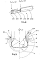
- La figure 3 compare l'invention à un état de la technique.
- Figure 1 is a perspective showing an embodiment of an apparatus according to the invention;
- Figure 2 is a detail of a presser of this apparatus;
- Figure 3 compares the invention to a state of the art.
A la figure 1, on voit que la forme est un noyau 1 (rigide et démontable, sans toutefois que ceci soit limitatif) définissant la géométrie de la surface intérieure du pneumatique. Celui-ci est revêtu de caoutchouc 10, par exemple d'une couche de gomme d'étanchéité à base de caoutchouc butyl, et d'une couche de gomme assurant l'enrobage des fils de carcasse. Le caoutchouc 10 recouvrant le noyau 1 permet de retenir des arceaux 40 de fil 4 sur le noyau 1 au fur et à mesure de sa dépose, par un effet de collage. Bien entendu, le noyau 1 est entraîné en rotation par tout dispositif convenable, non représenté.In Figure 1, we see that the shape is a core 1 (rigid and removable, without this being limiting) defining the geometry of the inner surface of the tire. This is coated with
Les organes de pose 3 proprement dits comportent essentiellement un système à un bras oscillant unique monobloc 31 d'une part, et des dispositifs presseurs 2G et 2D d'autre part. Le bras oscillant unique monobloc 31 est monté sur un arbre oscillant 3D dont on voit l'axe géométrique de rotation 31R. L'axe géométrique de rotation 31R coupe le noyau 1, en position de fonctionnement pour la pose de fil 4 sur le noyau. Le bras oscillant unique monobloc 31 comporte une base 310 orientée sensiblement perpendiculairement à l'axe géométrique de rotation 31R. Le bras oscillant unique monobloc 31 comporte une partie intermédiaire 31I se développant sensiblement parallèlement à l'axe géométrique de rotation, en direction du plan de mouvement. Le bras oscillant unique monobloc 31 comporte un bec 31T à l'extrémité du bras 31 opposée à l'axe géométrique de rotation 31R. Enfin, à l'extrémité du bec 31T, on trouve un orifice 6 remplissant la fonction remplie par l'oeilleton « 33 » dans la demande de brevet EP 0 580 055 précitée. Le bras oscillant unique monobloc 31 est monté sur un passage 3D1 aménagé sur l'arbre 3D, et est immobilisé au moyen d'un flasque 3D2. On dispose ainsi d'une coulisse permettant de modifier la position relative du bras oscillant unique monobloc 31 sur l'arbre 3D, afin de pouvoir régler le rayon R (figure 3) du cercle décrit par l'orifice 6.The
L'arbre 3D est monté sur un boîtier 30 comportant un dispositif mécanique de commande, approprié pour transformer le mouvement de rotation d'un moteur 300 en mouvement d'oscillations imprimées audit arbre 3D. Ledit arbre 3D oscille dans les limites d'un arc dont la valeur précise dépend de l'amplitude souhaitée pour le mouvement de l'orifice 6. Le dispositif de commande, du genre à bielle et manivelle ou tout autre disposition convenable, est dessiné aisément en fonction d'un cahier des charges dépendant de l'application visée et est animé par un moteur 300. Le système à un bras oscillant 31 permet d'obtenir, en conjonction avec les dispositifs presseurs 2G et 2D, une action de l'appareil d'un bourrelet à l'autre.The 3D shaft is mounted on a
Les dispositifs presseurs 2G et 2D sont positionnés de façon appropriée pour jouer le rôle décrit dans la demande de brevet EP 0 580 055 précitée. A la figure 2, on voit plus particulièrement le presseur 2D qui comporte une fourche 21D et un marteau 22D, tous deux mobiles entre une position reculée, en R (position éloignée du noyau 1), et une position avancée, en A. Ces positions sont notées A/R et R/A à la figure 1. On voit en trait discontinu le marteau en position avancée. En ce qui concerne les références aux figures, la convention utilisée est de désigner chacun des organes des presseurs par une référence principale, par exemple « 21 » pour la fourche, et de marquer l'appartenance spécifique au presseur d'un côté, le côté gauche ou le côté droit à la figure 1, par respectivement la lettre « G » ou « D » placée en exposant. Une référence sans marque spécifique renvoie de façon générique indifféremment à l'un ou l'autre des presseurs ou à leurs organes.The
Le lecteur est à nouveau invité à consulter la partie adéquate de la description de la demande de brevet EP 0 580 055 précitée, pour un rappel des fonctions respectives de la fourche et du marteau 22, et pour un rappel des rôles respectifs des positions dites avancée A et reculée R. A la figure 2, on voit qu'aussi bien la fourche 21 que le marteau 22 ont l'allure de lames parallèles. La fourche 21 est, par rapport au marteau, toujours disposée radialement du côté de l'axe de rotation du noyau 1. Soulignons cependant que l'on peut adopter une disposition exactement inverse : le marteau 22 plus proche de l'axe de rotation que la fourche 21.The reader is again invited to consult the appropriate part of the description of the aforementioned patent application EP 0 580 055, for a reminder of the respective functions of the fork and the
La fourche 21 a un bec 210 en « V », permettant de prendre et de centrer le fil 4. Pendant la phase de préhension, le plan formé par le « V » est disposé sensiblement perpendiculairement au fil 4. Lorsque le fil 4 doit être disposé radialement, cas de la figure 1, la lame formant la fourche 21 est orientée de façon tangente à un cercle concentrique au noyau 1. La fourche 21 comporte aussi un évidemment 211 dont le rôle apparaîtra ci-dessous.Fork 21 has a beak 210 at "V", making it possible to pick up and center the
La fourche 21 est destinée à emporter le fil 4 contre le noyau 1, puis à l'y maintenir. A cette fin, son avance vers le noyau 1 est déclenchée lorsque l'orifice 6 a amené le fil 4 à une extrémité du mouvement en va-et-vient, c'est à dire lorsque l'appareil est sensiblement dans la configuration de la figure 1. La fourche 21 est arrêtée lorsqu'elle a ancré le fil dans le caoutchouc revêtant le noyau 1. Ladite fourche 21 permet donc de plaquer le fil 4 avec une force suffisante pour qu'il adhère correctement à l'endroit souhaité.The fork 21 is intended to carry the
Compte tenu du pas de pose souhaité, lui-même fonction du mouvement de rotation du noyau 1 schématisé par la flèche F, la poursuite du mouvement du système à bras oscillant 3 provoque la formation d'une boucle autour de la pointe 212, ce qui amorce la dépose d'un nouvel arceau 40 sur le noyau 1 (voir figure 1). Et le passage de l'orifice 6 au-delà de la fourche 21 en phase de retour est permis par l'évidemment 211, bien que la fourche 21 soit plaquée contre le noyau 1 dans cette phase de la fabrication. Signalons que la taille de la boucle est fonction de la dimension de la pointe 212.Given the desired pitch, itself a function of the rotational movement of the core 1 shown schematically by the arrow F, the continued movement of the
Le marteau 22 intervient après la fourche 21 et après la phase dite de retour de l'orifice 6. Dans l'exemple considéré ici, le marteau 22 appuie sur le fil 4 à une position radiale un peu plus élevée. De préférence, il retient encore le fil 4 pendant que l'on rétracte la fourche 21. Le maintien du marteau pendant que la fourche se rétracte aide à éviter que la fourche 21 n'emporte avec elle la boucle de fil 4 qui s'est formée autour d'une de ses pointes 212, et qui même si elle est collée sur le caoutchouc, pourrait avoir tendance à rester solidaire de la fourche. L'ancrage du fil 4 dans le bourrelet s'en trouve parfaitement fiabilisé.The
Bien entendu, le mouvement en position avancée, et le retour en position reculée, aussi bien pour la fourche 21 que pour le marteau 22 (voir double flèches A/R et R/A à la figure 1), sont commandés en synchronisme avec le système à bras oscillant 3, par tout dispositif convenable (renvoi de mouvement de l'arbre 3D par une transmission mécanique appropriée, par exemple à courroies ou à câble ou par synchronisation électrique entre plusieurs moteurs).Of course, the movement in the advanced position, and the return to the retracted position, both for the fork 21 and for the hammer 22 (see double arrows A / R and R / A in FIG. 1), are controlled in synchronism with the
La figure 1 montre aussi que le fil 4 est amené jusqu'à une poulie folle 301 située sensiblement sur l'axe géométrique de rotation 31R du bras oscillant. Ensuite, le fil pénètre et chemine à l'intérieur du bras oscillant 31, ledit bras étant creux.FIG. 1 also shows that the
Le bras oscillant 31 fait décrire à l'orifice 6 un mouvement survolant le noyau 1, et même le contournant. Le système à bras oscillant 31 fait parcourir à l'orifice 6 un mouvement dans un plan, le « plan de mouvement ». Il convient de soigner la réalisation des rebords de l'orifice 6 pour ne pas blesser le fil 4, car le brin de sortie de celui-ci se dispose généralement sensiblement dans le plan de mouvement, c'est à dire dans un plan qui est perpendiculaire à l'axe de rotation 31R.The
A la figure 3, l'angle α représente la position instantanée du bras oscillant 31. L'angle α varie sur une amplitude suffisante pour que le fil déposé atteigne les zones d'extrémité de trajectoire. Il convient que l'orifice 6 aille au delà de l'endroit où intervient le dispositif presseur 2. On voit que l'orifice 6 de l'arbre 31, au bout du bec 31T, s'approche de la surface de dépose du fil aussi prêt que souhaitable. Le fil 4 est lui-même très proche de la couche de caoutchouc 10 tout le long du flanc, et notamment à l'endroit où il est pris en charge par les presseurs 2. On voit que la partie intermédiaire 31I n'interfère pas avec la forme 1. Le bec 31T permet malgré tout de positionner l'orifice 6 tout proche du bourrelet.In FIG. 3, the angle α represents the instantaneous position of the
La partie gauche de la figure 3 illustre un appareil à bras unique 39, parallèle à l'axe géométrique de rotation dudit bras 39, et dépourvu de bec. L'orifice 6 est disposé directement à l'extrémité de la partie parallèle à l'axe géométrique de rotation. On voit que l'appareil sans bec ne permet pas de s'approcher aussi prêt de l'extrémité de la trajectoire d'un arceau de fil déposé sur le noyau. On constate l'écart important du fil 4 par rapport à la surface de dépose, créant une difficulté pour la précision de dépose du fil 4.The left part of Figure 3 illustrates a single-
L'orifice 6 de l'appareil selon l'invention décrit un mouvement de va-et-vient d'un bourrelet à l'autre, ou plus précisément d'un endroit proche d'un bourrelet, à un endroit proche de l'autre bourrelet. Le cycle de base du fonctionnement de appareil selon l'invention comporte les étapes suivantes :
- le fil étant retenu contre la forme pendant un temps suffisant, déplacer l'orifice (organe de guidage) dans un plan de mouvement d'orifice jusqu'à une première extrémité,
- appliquer le fil sur la forme à cette première extrémité et l'y maintenir au moins un temps suffisant, au moyen d'un dispositif presseur,
- répéter la première étape en sens inverse jusqu'à une deuxième extrémité,
- appliquer le fil sur la forme à cette deuxième extrémité et l'y maintenir, au moyen d'un autre dispositif presseur,
- the wire being retained against the shape for a sufficient time, moving the orifice (guide member) in an orifice movement plane to a first end,
- apply the wire to the shape at this first end and hold it there for at least a sufficient time, by means of a pressing device,
- repeat the first step in reverse to a second end,
- apply the yarn on the shape to this second end and hold it there, by means of another pressing device,
Même si, dans cet exemple, l'orifice 6 décrit un mouvement dont le tracé est symétrique par rapport à au plan médian CP, et atteint le voisinage de chacune des zones de bourrelet définies sur le noyau 1, dans un mouvement parfaitement symétrique, cela n'est pas limitatif. Il n'est pas exclu que les extrémités du mouvement de l'orifice ne soient pas en des points symétriques par rapport au plan médian, par exemple pour fabriquer un pneumatique dont la trajectoire des arceaux ne serait pas symétrique. Ce serait le cas pour fabriquer un pneumatique dont les diamètres au seat (terme usuel pour désigner le siège de montage) de chacun des bourrelets sont différents.Although, in this example, the
L'exemple précédent (figure 1) illustre un appareil posant des tronçons de fils d'un bourrelet à l'autre bourrelet. On peut aussi réaliser ou utiliser des appareils agissant d'un bourrelet à une épaule, par exemple pour la fabrication d'une demi-carcasse. Il est en effet connu que la carcasse d'un pneumatique radial peut ne pas être continue d'un bourrelet à l'autre, mais peut être interrompue quelque part sous la bande de roulement. Le renfort de carcasse est alors déposé entre le bourrelet et une épaule. Un appareil selon l'invention pourrait tout aussi bien être utilisé pour une action d'un bourrelet jusqu'à n'importe quel point sous la bande de roulement, y compris jusqu'à l'épaule opposée, avec un certain degré de chevauchement des demi-carcasses l'une sur l'autre.The previous example (Figure 1) illustrates an apparatus laying sections of son from one bead to the other bead. It is also possible to make or use devices acting from a bead to a shoulder, for example for the manufacture of a half-carcass. It is known that the carcass of a radial tire may not be continuous from one bead to the other, but may be interrupted somewhere under the tread. The carcass reinforcement is then deposited between the bead and a shoulder. An apparatus according to the invention could equally well be used for an action of a bead up to any point under the tread, including up to the opposite shoulder, with a certain degree of overlap of half-carcasses one on the other.
Rappelons que l'orifice 6 de l'appareil selon l'invention est animé d'un mouvement cyclique dans un plan, appelé ici « plan de mouvement ». Le noyau 1 est entraîné en rotation autour de son axe pendant que l'orifice 6 effectue ses va-et-vient dans le plan de mouvement d'orifice. Bien entendu, le mouvement du noyau 1 est en synchronisme avec le mouvement de va-et-vient de l'orifice. La trajectoire réelle des arceaux 40 du fil 4 est donc à la fois fonction de la position fixe relative (qui peut être inclinée) entre le plan de mouvement d'orifice et le noyau, et est fonction du mouvement relatif entre le noyau 1 et le va-et-vient de l'orifice 6.Recall that the
Dans l'exemple décrit, la trajectoire de l'arceau 40 est sensiblement radiale parce qu'on y décrit la réalisation d'une carcasse pour un pneumatique radial, sans que bien entendu cela ne soit limitatif. Le plan de mouvement pourrait aussi former un angle quelconque, par exemple de l'ordre de 75°, par rapport à un plan perpendiculaire à l'axe de rotation du noyau 1, selon les conventions usuelles pour mesurer les angles dans le domaine du pneumatique. Les dispositifs presseurs 2G et 2D agissent dans le même plan de dépose.In the example described, the trajectory of the arch 40 is substantially radial because it describes the realization of a carcass for a radial tire, without, of course, being limiting. The plane of movement could also form any angle, for example of the order of 75 °, with respect to a plane perpendicular to the axis of rotation of the core 1, according to the usual conventions for measuring the angles in the field of the tire. . The
Pour réaliser une carcasse croisée dans les flancs, on peut éloigner le plan de mouvement d'orifice d'une orientation purement radiale, par inclinaison du support des organes de pose (comme le boîtier 30) autour d'un axe parallèle à l'axe de rotation du noyau 1. On peut encore, sans rien changer aux organes de l'appareil tel que décrit, changer l'azimut du noyau d'un angle important, par exemple 1/8 de tour pour un va-et-vient du système à bras oscillant 31, de sorte que l'on obtient un angle de pose du fil qui est fonction du rapport des déplacements (alors que dans l'exemple précédent, la vitesse du noyau 1 n'agissait que sur le seul pas de pose).To make a carcass crossed in the flanks, it is possible to move the orifice movement plane away from a purely radial orientation, by inclining the support of the positioning members (such as the housing 30) around an axis parallel to the axis rotation of the core 1. It is still possible, without changing anything to the organs of the apparatus as described, change the azimuth of the nucleus of a large angle, for example 1/8 of a turn for a back and forth of the
La remarque suivante explique une variante possible. On peut animer le support des organes de pose (comme le boîtier 30 - voir figure 1) d'un mouvement alternatif dans le but d'infléchir la trajectoire de pose du fil 4 sur le noyau 1. On peut par exemple animer le support des organes de pose d'un mouvement de translation alternatif (voir double flèche P à la figure 1) permettant de translater le plan de mouvement d'orifice selon une direction perpendiculaire au plan de mouvement. On peut aussi animer le support des organes de pose d'un mouvement d'oscillations autour d'un axe géométrique perpendiculaire à la surface de la forme, compris dans le plan de mouvement et coupant l'axe géométrique de rotation du bras oscillant (voir double flèche Q autour de l'axe M-M à la figure 1), permettant de faire osciller le plan de mouvement autour d'un axe parallèle audit plan de mouvement. On peut encore animer le support des organes de pose d'un mouvement d'oscillations autour de tout axe parallèle au précédent. Il faut bien distinguer une telle conception d'un simple réglage fixe (également possible et utile dans certains cas) de l'angle que fait le boîtier 30 autour de l'axe MM. Cela donne un degré de liberté supplémentaire pour agir sur la forme exacte de la trajectoire du fil 4.The following remark explains a possible variant. It is possible to animate the support of the positioning members (such as the housing 30 - see FIG. 1) of a reciprocating movement in order to bend the laying path of the
L'ensemble des organes de pose, à savoir le système à bras oscillant 31 et les dispositifs presseurs 2, y compris le moteur et le mécanisme d'entraînement, forme un sous-ensemble pouvant facilement être présenté au noyau de façon appropriée, et pouvant être escamoté pour par exemple présenter au noyau d'autres dispositifs utilisés pour la fabrication d'un pneumatique ou pour l'évacuation du noyau vers d'autres postes de confection d'un pneumatique.All of the installation members, namely the
Claims (6)
- Apparatus for producing a tyre reinforcement, the said apparatus being intended to produce a reinforcement formed from a thread (4) delivered continuously and on request by an appropriate dispenser, the said apparatus being intended to be used in cooperation with a substantially toroidal form (1) on which the said reinforcement is progressively constructed by laying hoops of the said thread on a desired path for the said thread on the surface of the said form,
the said apparatus comprising:• a guiding member (6) in which the thread can slide freely,• a single monobloc oscillating arm (31), moving about a geometrical axis of rotation (31 R), the end of the said arm supporting the said guiding member,• a control for imparting an oscillatory movement to the said oscillating arm so that the guiding member is transported in a cyclical movement described in a movement plane, to and fro, in order to bring the guiding member in successive cycles into the vicinity of each of the desired ends for the thread in the said path,• pressers (2G and 2D) close to each end of the said path, for applying the thread to the form at the said ends, acting in synchronism with the said cyclical movement of the guiding member,characterised in that
the said arm comprises, in its terminal part, a spout (31T) curved towards the said geometrical axis of rotation (31R), the said spout directly supporting the guiding member (6) so as to bring the guiding member close to the said form at least in the configuration assumed by the apparatus when the guiding member is close to the end of the said path. - Apparatus according to Claim 1, in which the single monobloc oscillating arm (31) is mounted on an oscillating shaft (3D) of geometrical axis of rotation (31R).
- Apparatus according to Claim 2, in which the single monobloc oscillating arm (31) is mounted in a passage (3D1) formed in the shaft (3D), so as to make it possible to modify the relative position of the oscillating arm (31) on the shaft (3D).
- Apparatus according to Claim 1 or 2, in which the geometrical axis of rotation of the single monobloc arm intersects the form in the working position.
- Apparatus according to one of Claims 1 to 3, in which the base (310) of the said arm (31) is substantially oriented perpendicularly to the geometrical axis of rotation of the said arm, the arm (31) having at least one intermediate part (311) oriented substantially parallel to the geometrical axis of rotation of the arm.
- Apparatus according to one of Claims 1 to 4, in which the guiding member consists of an orifice (6) at the end of the oscillating arm, the said arm being hollow and having the said thread passing though it.
Applications Claiming Priority (2)
| Application Number | Priority Date | Filing Date | Title |
|---|---|---|---|
| FR0101747 | 2001-02-07 | ||
| FR0101747 | 2001-02-07 |
Publications (3)
| Publication Number | Publication Date |
|---|---|
| EP1231049A2 EP1231049A2 (en) | 2002-08-14 |
| EP1231049A3 EP1231049A3 (en) | 2003-05-02 |
| EP1231049B1 true EP1231049B1 (en) | 2007-03-14 |
Family
ID=8859806
Family Applications (1)
| Application Number | Title | Priority Date | Filing Date |
|---|---|---|---|
| EP02001861A Expired - Lifetime EP1231049B1 (en) | 2001-02-07 | 2002-01-28 | Swing arm apparatus for manufacturing a tyre reinforcing structure using a single thread |
Country Status (5)
| Country | Link |
|---|---|
| US (1) | US6929047B2 (en) |
| EP (1) | EP1231049B1 (en) |
| JP (1) | JP4301485B2 (en) |
| AT (1) | ATE356712T1 (en) |
| DE (1) | DE60218771T2 (en) |
Families Citing this family (15)
| Publication number | Priority date | Publication date | Assignee | Title |
|---|---|---|---|---|
| FR2827806A1 (en) * | 2001-07-26 | 2003-01-31 | Michelin Soc Tech | APPARATUS FOR MANUFACTURING A REINFORCEMENT FOR TIRES |
| ATE340070T1 (en) * | 2002-12-04 | 2006-10-15 | Michelin Soc Tech | DEVICE FOR PRODUCING A REINFORCEMENT ELEMENT FOR LARGE-SIZE AIR TIRES |
| FR2848141A1 (en) * | 2002-12-04 | 2004-06-11 | Michelin Soc Tech | APPARATUS FOR MANUFACTURING A REINFORCEMENT FOR TIRES, WITH MULTIPLE LAYING ARMS COMPRISING A MOVEMENT GUIDED BY A CAM TRACK SLIDING IN LIGHT |
| US20040154727A1 (en) * | 2003-02-11 | 2004-08-12 | Weissert James Thomas | Method and apparatus for manufacturing carcass plies for a tire |
| FR2877873B1 (en) * | 2004-11-12 | 2007-02-09 | Michelin Soc Tech | APPARATUS FOR MANUFACTURING PNEUMATIC REINFORCEMENT |
| US7686053B2 (en) * | 2005-12-01 | 2010-03-30 | The Goodyear Tire & Rubber Company | Cord tensioning and feed mechanism for a tire cord applicator head |
| US20070125480A1 (en) * | 2005-12-01 | 2007-06-07 | Henthorne David A | Synchronous drive and method for tire cord application |
| US20070125482A1 (en) * | 2005-12-01 | 2007-06-07 | Weissert James T | Bi-directional tooling head and method for tire cord application |
| US20070125471A1 (en) * | 2005-12-01 | 2007-06-07 | Weissert James T | Split cord geodesic configurations for a tire |
| US20070125478A1 (en) * | 2005-12-01 | 2007-06-07 | Weissert James T | Tire cord application station and method |
| US7740039B2 (en) * | 2005-12-01 | 2010-06-22 | The Goodyear Tire & Rubber Company | Cord cutting mechanism and method for a tire cord applicator head |
| US7753098B2 (en) * | 2005-12-01 | 2010-07-13 | The Goodyear Tire & Rubber Company | Spring loaded tooling head and method for tire cord application |
| US8578994B2 (en) * | 2006-12-19 | 2013-11-12 | The Goodyear Tire & Rubber Company | Applicator head for tire cord construction |
| EP2565023B1 (en) * | 2011-08-31 | 2014-05-14 | SSM Schärer Schweiter Mettler AG | thread laying device |
| JP6708230B2 (en) * | 2018-08-07 | 2020-06-10 | 横浜ゴム株式会社 | Pneumatic tire manufacturing method and molding apparatus |
Family Cites Families (6)
| Publication number | Priority date | Publication date | Assignee | Title |
|---|---|---|---|---|
| GB179312A (en) * | 1921-02-03 | 1922-05-03 | Dunlop Rubber Co | Improvements in or relating to machines for making pneumatic tyre covers or casings |
| FR2603841B1 (en) * | 1986-09-17 | 1989-02-24 | Michelin & Cie | METHOD OF MANUFACTURING A TIRE WITH LAYING RUBBER PRODUCTS AND REINFORCING ELEMENTS ON A SUPPORT, DEVICE FOR LAYING RUBBER PRODUCTS AND MACHINE USING SUCH DEVICE (S) |
| ES2099324T3 (en) | 1992-07-21 | 1997-05-16 | Sedepro | PROCEDURE AND MACHINE FOR THE PLACEMENT IN A NUCLEUS OF A SINGLE THREAD OF REINFORCEMENT IN THE MANUFACTURE OF A TIRE CASE. |
| FR2804367B1 (en) | 2000-02-01 | 2002-09-20 | Sedepro | OSCILLATING ARM APPARATUS FOR MANUFACTURING A TIRE REINFORCEMENT FROM A SINGLE THREAD |
| JP4233658B2 (en) | 1998-06-01 | 2009-03-04 | 株式会社ブリヂストン | Carcass cord attaching apparatus and tire manufacturing method |
| FR2804368A1 (en) * | 2000-02-01 | 2001-08-03 | Sedepro | APPARATUS FOR MANUFACTURING TIRE REINFORCEMENTS |
-
2002
- 2002-01-28 EP EP02001861A patent/EP1231049B1/en not_active Expired - Lifetime
- 2002-01-28 DE DE60218771T patent/DE60218771T2/en not_active Expired - Lifetime
- 2002-01-28 AT AT02001861T patent/ATE356712T1/en not_active IP Right Cessation
- 2002-01-31 US US10/066,044 patent/US6929047B2/en not_active Expired - Lifetime
- 2002-02-07 JP JP2002030606A patent/JP4301485B2/en not_active Expired - Fee Related
Also Published As
| Publication number | Publication date |
|---|---|
| EP1231049A2 (en) | 2002-08-14 |
| ATE356712T1 (en) | 2007-04-15 |
| DE60218771T2 (en) | 2007-12-13 |
| DE60218771D1 (en) | 2007-04-26 |
| EP1231049A3 (en) | 2003-05-02 |
| US20020117251A1 (en) | 2002-08-29 |
| JP4301485B2 (en) | 2009-07-22 |
| US6929047B2 (en) | 2005-08-16 |
| JP2002240161A (en) | 2002-08-28 |
Similar Documents
| Publication | Publication Date | Title |
|---|---|---|
| EP1464472B1 (en) | Swing arm apparatus for manufacturing a tyre reinforcing structure using a single thread | |
| EP1231049B1 (en) | Swing arm apparatus for manufacturing a tyre reinforcing structure using a single thread | |
| EP1537985B1 (en) | Swing arm apparatus for manufacturing a tyre reinforcing structure using a single thread | |
| EP0580055B1 (en) | Process and apparatus for arranging on a core a single reinforcing wire in the manufacturing of tire carcasses | |
| EP0248301B1 (en) | Method and apparatus for making a reinforcement for a tyre | |
| EP0243851B1 (en) | Method and apparatus for making reinforcements for pneumatic tyres | |
| CA2071445C (en) | Tire fabrication process, and machines for implementing said process | |
| EP1122055B1 (en) | Combined movement apparatus for the manufacture of tyre reinforcements using a single cord | |
| EP1517781A1 (en) | Device for producing a reinforcing structure for a tyre, comprising a strip turning mechanism | |
| EP0519295A1 (en) | Method for the production of a tyre and apparatus for the implementation of the method | |
| EP1711335B1 (en) | Method and device for producing a tyre reinforcement | |
| EP1426170B1 (en) | Apparatus having multiple application arms for the manufacture of a reinforcing element for tyres | |
| EP1513672B1 (en) | System for producing a reinforcing structure for a tyre with volumetric control of the die | |
| EP1590169B1 (en) | Apparatus for producing a tire reinforcement provided with a device for guiding the reinforcing wire and method of manufacturing a tire reinforcement using such an apparatus. | |
| EP1426169B1 (en) | Apparatus for the manufacture of a reinforcing element for large-dimension tyres | |
| EP1279484B1 (en) | Method and Apparatus for the manufacture of a reinforcing structure for a tyre | |
| EP1824666B1 (en) | Appliance for producing a reinforcement for a pneumatic tyre | |
| EP0353511A1 (en) | Constituent parts of an apparatus for making tyre reinforcements |
Legal Events
| Date | Code | Title | Description |
|---|---|---|---|
| PUAI | Public reference made under article 153(3) epc to a published international application that has entered the european phase |
Free format text: ORIGINAL CODE: 0009012 |
|
| AK | Designated contracting states |
Kind code of ref document: A2 Designated state(s): AT BE CH CY DE DK ES FI FR GB GR IE IT LI LU MC NL PT SE TR |
|
| AX | Request for extension of the european patent |
Free format text: AL;LT;LV;MK;RO;SI |
|
| PUAL | Search report despatched |
Free format text: ORIGINAL CODE: 0009013 |
|
| AK | Designated contracting states |
Designated state(s): AT BE CH CY DE DK ES FI FR GB GR IE IT LI LU MC NL PT SE TR |
|
| AX | Request for extension of the european patent |
Extension state: AL LT LV MK RO SI |
|
| 17P | Request for examination filed |
Effective date: 20031103 |
|
| AKX | Designation fees paid |
Designated state(s): AT BE CH CY DE DK ES FI FR GB GR IE IT LI LU MC NL PT SE TR |
|
| 17Q | First examination report despatched |
Effective date: 20040224 |
|
| GRAP | Despatch of communication of intention to grant a patent |
Free format text: ORIGINAL CODE: EPIDOSNIGR1 |
|
| GRAS | Grant fee paid |
Free format text: ORIGINAL CODE: EPIDOSNIGR3 |
|
| GRAA | (expected) grant |
Free format text: ORIGINAL CODE: 0009210 |
|
| AK | Designated contracting states |
Kind code of ref document: B1 Designated state(s): AT BE CH CY DE DK ES FI FR GB GR IE IT LI LU MC NL PT SE TR |
|
| PG25 | Lapsed in a contracting state [announced via postgrant information from national office to epo] |
Ref country code: IE Free format text: LAPSE BECAUSE OF FAILURE TO SUBMIT A TRANSLATION OF THE DESCRIPTION OR TO PAY THE FEE WITHIN THE PRESCRIBED TIME-LIMIT Effective date: 20070314 Ref country code: FI Free format text: LAPSE BECAUSE OF FAILURE TO SUBMIT A TRANSLATION OF THE DESCRIPTION OR TO PAY THE FEE WITHIN THE PRESCRIBED TIME-LIMIT Effective date: 20070314 Ref country code: NL Free format text: LAPSE BECAUSE OF FAILURE TO SUBMIT A TRANSLATION OF THE DESCRIPTION OR TO PAY THE FEE WITHIN THE PRESCRIBED TIME-LIMIT Effective date: 20070314 Ref country code: AT Free format text: LAPSE BECAUSE OF FAILURE TO SUBMIT A TRANSLATION OF THE DESCRIPTION OR TO PAY THE FEE WITHIN THE PRESCRIBED TIME-LIMIT Effective date: 20070314 |
|
| REG | Reference to a national code |
Ref country code: GB Ref legal event code: FG4D Free format text: NOT ENGLISH |
|
| REG | Reference to a national code |
Ref country code: CH Ref legal event code: EP |
|
| REF | Corresponds to: |
Ref document number: 60218771 Country of ref document: DE Date of ref document: 20070426 Kind code of ref document: P |
|
| REG | Reference to a national code |
Ref country code: IE Ref legal event code: FG4D Free format text: LANGUAGE OF EP DOCUMENT: FRENCH |
|
| PG25 | Lapsed in a contracting state [announced via postgrant information from national office to epo] |
Ref country code: SE Free format text: LAPSE BECAUSE OF FAILURE TO SUBMIT A TRANSLATION OF THE DESCRIPTION OR TO PAY THE FEE WITHIN THE PRESCRIBED TIME-LIMIT Effective date: 20070614 |
|
| PG25 | Lapsed in a contracting state [announced via postgrant information from national office to epo] |
Ref country code: ES Free format text: LAPSE BECAUSE OF FAILURE TO SUBMIT A TRANSLATION OF THE DESCRIPTION OR TO PAY THE FEE WITHIN THE PRESCRIBED TIME-LIMIT Effective date: 20070625 |
|
| PG25 | Lapsed in a contracting state [announced via postgrant information from national office to epo] |
Ref country code: PT Free format text: LAPSE BECAUSE OF FAILURE TO SUBMIT A TRANSLATION OF THE DESCRIPTION OR TO PAY THE FEE WITHIN THE PRESCRIBED TIME-LIMIT Effective date: 20070814 |
|
| NLV1 | Nl: lapsed or annulled due to failure to fulfill the requirements of art. 29p and 29m of the patents act | ||
| GBV | Gb: ep patent (uk) treated as always having been void in accordance with gb section 77(7)/1977 [no translation filed] |
Effective date: 20070314 |
|
| REG | Reference to a national code |
Ref country code: IE Ref legal event code: FD4D |
|
| PG25 | Lapsed in a contracting state [announced via postgrant information from national office to epo] |
Ref country code: GB Free format text: LAPSE BECAUSE OF FAILURE TO SUBMIT A TRANSLATION OF THE DESCRIPTION OR TO PAY THE FEE WITHIN THE PRESCRIBED TIME-LIMIT Effective date: 20070314 |
|
| PLBE | No opposition filed within time limit |
Free format text: ORIGINAL CODE: 0009261 |
|
| STAA | Information on the status of an ep patent application or granted ep patent |
Free format text: STATUS: NO OPPOSITION FILED WITHIN TIME LIMIT |
|
| PG25 | Lapsed in a contracting state [announced via postgrant information from national office to epo] |
Ref country code: DK Free format text: LAPSE BECAUSE OF FAILURE TO SUBMIT A TRANSLATION OF THE DESCRIPTION OR TO PAY THE FEE WITHIN THE PRESCRIBED TIME-LIMIT Effective date: 20070314 |
|
| 26N | No opposition filed |
Effective date: 20071217 |
|
| PG25 | Lapsed in a contracting state [announced via postgrant information from national office to epo] |
Ref country code: GR Free format text: LAPSE BECAUSE OF FAILURE TO SUBMIT A TRANSLATION OF THE DESCRIPTION OR TO PAY THE FEE WITHIN THE PRESCRIBED TIME-LIMIT Effective date: 20070615 |
|
| BERE | Be: lapsed |
Owner name: SOC. DE TECHNOLOGIE MICHELIN Effective date: 20080131 Owner name: MICHELIN RECHERCHE ET TECHNIQUE S.A. Effective date: 20080131 |
|
| PG25 | Lapsed in a contracting state [announced via postgrant information from national office to epo] |
Ref country code: MC Free format text: LAPSE BECAUSE OF NON-PAYMENT OF DUE FEES Effective date: 20080131 |
|
| REG | Reference to a national code |
Ref country code: CH Ref legal event code: PL |
|
| PG25 | Lapsed in a contracting state [announced via postgrant information from national office to epo] |
Ref country code: LI Free format text: LAPSE BECAUSE OF NON-PAYMENT OF DUE FEES Effective date: 20080131 Ref country code: CH Free format text: LAPSE BECAUSE OF NON-PAYMENT OF DUE FEES Effective date: 20080131 |
|
| PG25 | Lapsed in a contracting state [announced via postgrant information from national office to epo] |
Ref country code: BE Free format text: LAPSE BECAUSE OF NON-PAYMENT OF DUE FEES Effective date: 20080131 |
|
| PG25 | Lapsed in a contracting state [announced via postgrant information from national office to epo] |
Ref country code: CY Free format text: LAPSE BECAUSE OF FAILURE TO SUBMIT A TRANSLATION OF THE DESCRIPTION OR TO PAY THE FEE WITHIN THE PRESCRIBED TIME-LIMIT Effective date: 20070314 |
|
| PG25 | Lapsed in a contracting state [announced via postgrant information from national office to epo] |
Ref country code: LU Free format text: LAPSE BECAUSE OF NON-PAYMENT OF DUE FEES Effective date: 20080128 |
|
| PG25 | Lapsed in a contracting state [announced via postgrant information from national office to epo] |
Ref country code: TR Free format text: LAPSE BECAUSE OF FAILURE TO SUBMIT A TRANSLATION OF THE DESCRIPTION OR TO PAY THE FEE WITHIN THE PRESCRIBED TIME-LIMIT Effective date: 20070314 |
|
| REG | Reference to a national code |
Ref country code: FR Ref legal event code: PLFP Year of fee payment: 15 |
|
| REG | Reference to a national code |
Ref country code: FR Ref legal event code: PLFP Year of fee payment: 16 |
|
| REG | Reference to a national code |
Ref country code: FR Ref legal event code: PLFP Year of fee payment: 17 |
|
| PGFP | Annual fee paid to national office [announced via postgrant information from national office to epo] |
Ref country code: DE Payment date: 20180122 Year of fee payment: 17 |
|
| PGFP | Annual fee paid to national office [announced via postgrant information from national office to epo] |
Ref country code: IT Payment date: 20180129 Year of fee payment: 17 Ref country code: FR Payment date: 20180119 Year of fee payment: 17 |
|
| REG | Reference to a national code |
Ref country code: DE Ref legal event code: R119 Ref document number: 60218771 Country of ref document: DE |
|
| PG25 | Lapsed in a contracting state [announced via postgrant information from national office to epo] |
Ref country code: DE Free format text: LAPSE BECAUSE OF NON-PAYMENT OF DUE FEES Effective date: 20190801 Ref country code: FR Free format text: LAPSE BECAUSE OF NON-PAYMENT OF DUE FEES Effective date: 20190131 |
|
| PG25 | Lapsed in a contracting state [announced via postgrant information from national office to epo] |
Ref country code: IT Free format text: LAPSE BECAUSE OF NON-PAYMENT OF DUE FEES Effective date: 20190128 |