EP1513672B1 - System for producing a reinforcing structure for a tyre with volumetric control of the die - Google Patents
System for producing a reinforcing structure for a tyre with volumetric control of the die Download PDFInfo
- Publication number
- EP1513672B1 EP1513672B1 EP03732489A EP03732489A EP1513672B1 EP 1513672 B1 EP1513672 B1 EP 1513672B1 EP 03732489 A EP03732489 A EP 03732489A EP 03732489 A EP03732489 A EP 03732489A EP 1513672 B1 EP1513672 B1 EP 1513672B1
- Authority
- EP
- European Patent Office
- Prior art keywords
- strip
- threads
- unit
- reinforcement structure
- composition
- Prior art date
- Legal status (The legal status is an assumption and is not a legal conclusion. Google has not performed a legal analysis and makes no representation as to the accuracy of the status listed.)
- Expired - Lifetime
Links
Images


Classifications
-
- B—PERFORMING OPERATIONS; TRANSPORTING
- B29—WORKING OF PLASTICS; WORKING OF SUBSTANCES IN A PLASTIC STATE IN GENERAL
- B29D—PRODUCING PARTICULAR ARTICLES FROM PLASTICS OR FROM SUBSTANCES IN A PLASTIC STATE
- B29D30/00—Producing pneumatic or solid tyres or parts thereof
- B29D30/06—Pneumatic tyres or parts thereof (e.g. produced by casting, moulding, compression moulding, injection moulding, centrifugal casting)
- B29D30/08—Building tyres
- B29D30/10—Building tyres on round cores, i.e. the shape of the core is approximately identical with the shape of the completed tyre
- B29D30/16—Applying the layers; Guiding or stretching the layers during application
- B29D30/1657—Applying the layers; Guiding or stretching the layers during application by feeding cut-to-length pieces in a direction inclined with respect to the core axis and placing the pieces side-by-side to form an annular element
-
- B—PERFORMING OPERATIONS; TRANSPORTING
- B29—WORKING OF PLASTICS; WORKING OF SUBSTANCES IN A PLASTIC STATE IN GENERAL
- B29C—SHAPING OR JOINING OF PLASTICS; SHAPING OF MATERIAL IN A PLASTIC STATE, NOT OTHERWISE PROVIDED FOR; AFTER-TREATMENT OF THE SHAPED PRODUCTS, e.g. REPAIRING
- B29C48/00—Extrusion moulding, i.e. expressing the moulding material through a die or nozzle which imparts the desired form; Apparatus therefor
- B29C48/03—Extrusion moulding, i.e. expressing the moulding material through a die or nozzle which imparts the desired form; Apparatus therefor characterised by the shape of the extruded material at extrusion
- B29C48/07—Flat, e.g. panels
- B29C48/08—Flat, e.g. panels flexible, e.g. films
-
- B—PERFORMING OPERATIONS; TRANSPORTING
- B29—WORKING OF PLASTICS; WORKING OF SUBSTANCES IN A PLASTIC STATE IN GENERAL
- B29C—SHAPING OR JOINING OF PLASTICS; SHAPING OF MATERIAL IN A PLASTIC STATE, NOT OTHERWISE PROVIDED FOR; AFTER-TREATMENT OF THE SHAPED PRODUCTS, e.g. REPAIRING
- B29C48/00—Extrusion moulding, i.e. expressing the moulding material through a die or nozzle which imparts the desired form; Apparatus therefor
- B29C48/15—Extrusion moulding, i.e. expressing the moulding material through a die or nozzle which imparts the desired form; Apparatus therefor incorporating preformed parts or layers, e.g. extrusion moulding around inserts
- B29C48/156—Coating two or more articles simultaneously
-
- B—PERFORMING OPERATIONS; TRANSPORTING
- B29—WORKING OF PLASTICS; WORKING OF SUBSTANCES IN A PLASTIC STATE IN GENERAL
- B29C—SHAPING OR JOINING OF PLASTICS; SHAPING OF MATERIAL IN A PLASTIC STATE, NOT OTHERWISE PROVIDED FOR; AFTER-TREATMENT OF THE SHAPED PRODUCTS, e.g. REPAIRING
- B29C48/00—Extrusion moulding, i.e. expressing the moulding material through a die or nozzle which imparts the desired form; Apparatus therefor
- B29C48/25—Component parts, details or accessories; Auxiliary operations
- B29C48/36—Means for plasticising or homogenising the moulding material or forcing it through the nozzle or die
- B29C48/365—Means for plasticising or homogenising the moulding material or forcing it through the nozzle or die using pumps, e.g. piston pumps
- B29C48/37—Gear pumps
-
- B—PERFORMING OPERATIONS; TRANSPORTING
- B29—WORKING OF PLASTICS; WORKING OF SUBSTANCES IN A PLASTIC STATE IN GENERAL
- B29C—SHAPING OR JOINING OF PLASTICS; SHAPING OF MATERIAL IN A PLASTIC STATE, NOT OTHERWISE PROVIDED FOR; AFTER-TREATMENT OF THE SHAPED PRODUCTS, e.g. REPAIRING
- B29C48/00—Extrusion moulding, i.e. expressing the moulding material through a die or nozzle which imparts the desired form; Apparatus therefor
- B29C48/25—Component parts, details or accessories; Auxiliary operations
- B29C48/36—Means for plasticising or homogenising the moulding material or forcing it through the nozzle or die
- B29C48/375—Plasticisers, homogenisers or feeders comprising two or more stages
- B29C48/387—Plasticisers, homogenisers or feeders comprising two or more stages using a screw extruder and a gear pump
-
- B—PERFORMING OPERATIONS; TRANSPORTING
- B29—WORKING OF PLASTICS; WORKING OF SUBSTANCES IN A PLASTIC STATE IN GENERAL
- B29C—SHAPING OR JOINING OF PLASTICS; SHAPING OF MATERIAL IN A PLASTIC STATE, NOT OTHERWISE PROVIDED FOR; AFTER-TREATMENT OF THE SHAPED PRODUCTS, e.g. REPAIRING
- B29C48/00—Extrusion moulding, i.e. expressing the moulding material through a die or nozzle which imparts the desired form; Apparatus therefor
- B29C48/25—Component parts, details or accessories; Auxiliary operations
- B29C48/36—Means for plasticising or homogenising the moulding material or forcing it through the nozzle or die
- B29C48/395—Means for plasticising or homogenising the moulding material or forcing it through the nozzle or die using screws surrounded by a cooperating barrel, e.g. single screw extruders
- B29C48/397—Means for plasticising or homogenising the moulding material or forcing it through the nozzle or die using screws surrounded by a cooperating barrel, e.g. single screw extruders using a single screw
-
- B—PERFORMING OPERATIONS; TRANSPORTING
- B29—WORKING OF PLASTICS; WORKING OF SUBSTANCES IN A PLASTIC STATE IN GENERAL
- B29C—SHAPING OR JOINING OF PLASTICS; SHAPING OF MATERIAL IN A PLASTIC STATE, NOT OTHERWISE PROVIDED FOR; AFTER-TREATMENT OF THE SHAPED PRODUCTS, e.g. REPAIRING
- B29C48/00—Extrusion moulding, i.e. expressing the moulding material through a die or nozzle which imparts the desired form; Apparatus therefor
- B29C48/25—Component parts, details or accessories; Auxiliary operations
- B29C48/92—Measuring, controlling or regulating
-
- B—PERFORMING OPERATIONS; TRANSPORTING
- B29—WORKING OF PLASTICS; WORKING OF SUBSTANCES IN A PLASTIC STATE IN GENERAL
- B29C—SHAPING OR JOINING OF PLASTICS; SHAPING OF MATERIAL IN A PLASTIC STATE, NOT OTHERWISE PROVIDED FOR; AFTER-TREATMENT OF THE SHAPED PRODUCTS, e.g. REPAIRING
- B29C2948/00—Indexing scheme relating to extrusion moulding
- B29C2948/92—Measuring, controlling or regulating
- B29C2948/92504—Controlled parameter
- B29C2948/92571—Position, e.g. linear or angular
-
- B—PERFORMING OPERATIONS; TRANSPORTING
- B29—WORKING OF PLASTICS; WORKING OF SUBSTANCES IN A PLASTIC STATE IN GENERAL
- B29C—SHAPING OR JOINING OF PLASTICS; SHAPING OF MATERIAL IN A PLASTIC STATE, NOT OTHERWISE PROVIDED FOR; AFTER-TREATMENT OF THE SHAPED PRODUCTS, e.g. REPAIRING
- B29C2948/00—Indexing scheme relating to extrusion moulding
- B29C2948/92—Measuring, controlling or regulating
- B29C2948/92504—Controlled parameter
- B29C2948/92609—Dimensions
- B29C2948/92638—Length
-
- B—PERFORMING OPERATIONS; TRANSPORTING
- B29—WORKING OF PLASTICS; WORKING OF SUBSTANCES IN A PLASTIC STATE IN GENERAL
- B29C—SHAPING OR JOINING OF PLASTICS; SHAPING OF MATERIAL IN A PLASTIC STATE, NOT OTHERWISE PROVIDED FOR; AFTER-TREATMENT OF THE SHAPED PRODUCTS, e.g. REPAIRING
- B29C2948/00—Indexing scheme relating to extrusion moulding
- B29C2948/92—Measuring, controlling or regulating
- B29C2948/92504—Controlled parameter
- B29C2948/92609—Dimensions
- B29C2948/92657—Volume or quantity
-
- B—PERFORMING OPERATIONS; TRANSPORTING
- B29—WORKING OF PLASTICS; WORKING OF SUBSTANCES IN A PLASTIC STATE IN GENERAL
- B29C—SHAPING OR JOINING OF PLASTICS; SHAPING OF MATERIAL IN A PLASTIC STATE, NOT OTHERWISE PROVIDED FOR; AFTER-TREATMENT OF THE SHAPED PRODUCTS, e.g. REPAIRING
- B29C2948/00—Indexing scheme relating to extrusion moulding
- B29C2948/92—Measuring, controlling or regulating
- B29C2948/92819—Location or phase of control
- B29C2948/92857—Extrusion unit
- B29C2948/92904—Die; Nozzle zone
-
- B—PERFORMING OPERATIONS; TRANSPORTING
- B29—WORKING OF PLASTICS; WORKING OF SUBSTANCES IN A PLASTIC STATE IN GENERAL
- B29C—SHAPING OR JOINING OF PLASTICS; SHAPING OF MATERIAL IN A PLASTIC STATE, NOT OTHERWISE PROVIDED FOR; AFTER-TREATMENT OF THE SHAPED PRODUCTS, e.g. REPAIRING
- B29C2948/00—Indexing scheme relating to extrusion moulding
- B29C2948/92—Measuring, controlling or regulating
- B29C2948/92819—Location or phase of control
- B29C2948/92942—Moulded article
-
- B—PERFORMING OPERATIONS; TRANSPORTING
- B29—WORKING OF PLASTICS; WORKING OF SUBSTANCES IN A PLASTIC STATE IN GENERAL
- B29C—SHAPING OR JOINING OF PLASTICS; SHAPING OF MATERIAL IN A PLASTIC STATE, NOT OTHERWISE PROVIDED FOR; AFTER-TREATMENT OF THE SHAPED PRODUCTS, e.g. REPAIRING
- B29C48/00—Extrusion moulding, i.e. expressing the moulding material through a die or nozzle which imparts the desired form; Apparatus therefor
- B29C48/25—Component parts, details or accessories; Auxiliary operations
- B29C48/285—Feeding the extrusion material to the extruder
- B29C48/288—Feeding the extrusion material to the extruder in solid form, e.g. powder or granules
- B29C48/2888—Feeding the extrusion material to the extruder in solid form, e.g. powder or granules in band or in strip form, e.g. rubber strips
-
- B—PERFORMING OPERATIONS; TRANSPORTING
- B29—WORKING OF PLASTICS; WORKING OF SUBSTANCES IN A PLASTIC STATE IN GENERAL
- B29D—PRODUCING PARTICULAR ARTICLES FROM PLASTICS OR FROM SUBSTANCES IN A PLASTIC STATE
- B29D30/00—Producing pneumatic or solid tyres or parts thereof
- B29D30/06—Pneumatic tyres or parts thereof (e.g. produced by casting, moulding, compression moulding, injection moulding, centrifugal casting)
- B29D30/08—Building tyres
- B29D30/10—Building tyres on round cores, i.e. the shape of the core is approximately identical with the shape of the completed tyre
- B29D30/16—Applying the layers; Guiding or stretching the layers during application
- B29D2030/1664—Details, accessories or auxiliary operations not provided for in the other subgroups of B29D30/00
- B29D2030/1685—Details, accessories or auxiliary operations not provided for in the other subgroups of B29D30/00 the layers being applied being already cut to the appropriate length, before the application step
Definitions
- the present invention relates to the manufacture of tires. More specifically, it relates to the establishment of son to form a reinforcing structure for tire. More particularly, it proposes means capable of producing such a reinforcement structure on a shape that is close to or identical to the shape of the internal cavity of the tire, that is to say a substantially toroidal shape, supporting the blank of a tire during its manufacture.
- GB 987983 discloses a method according to which semi-finished products are prepared on a first machine and then a tire is assembled from these semi-finished products on another machine.
- the technique of manufacturing reinforcement structures from a strip has not found many industrial applications because, on the one hand, it does not have the productivity of manufacturing from tablecloths, and of on the other hand, it does not have the flexibility and precision of a manufacturing technique from an individual thread.
- you want to make a pneumatic according to a technique providing little or no conformation of the raw product during its manufacture it is of primary importance to be able to deposit the reinforcement structures and the raw rubber products constituting the future tire with a very high accuracy also well on their positioning than on the amount of material deposited on the form of manufacture.
- the object of the present invention is to provide a method and an apparatus that allow the manufacture of a tire reinforcement structure by depositing on a form of manufacture, and this with very high laying precision, very good efficiency, and by means as simple as possible, pledges of a very great industrial robustness.
- this form of manufacture is close to the shape of the internal cavity of the future tire.
- the present invention refers to a method of manufacturing a tire according to the steps specified in claim 1.
- the present invention also refers to an apparatus for manufacturing a tire reinforcing structure according to the features specified in claim 10.
- the apparatus allows the strip to be deposited on said shape, with a reversal of one layer to the next.
- the term "wire” must of course be understood in a very general sense, including a monofilament, a multifilament, an assembly such as a cable or a twist, or a small number of cables or twisted bundles, and this regardless of the nature of the material, and that the wire is pre-coated with an elastomer such as rubber or not.
- the term “strip” is used to designate an assembly of several parallel threads joined together by a raw rubber matrix.
- the term “stump” is used to designate a piece of strip, created by cutting a certain length of strip. A strip of strip allows the removal of several arches of wire.
- hoop is a limited length of yarn, ranging from one singular point to another in the tire as a finished, vulcanized product.
- trajectory is the exact trace of an arch in the finished tire.
- a set of hoops arranged around the entire periphery of the tire forms a reinforcing structure.
- a hoop, as defined herein, may be part of a carcass, or a crown reinforcement, or any other type of reinforcement structure.
- the invention deals with the removal of successive sections of wire strip, in a configuration as close as possible to the configuration in the final product. It matters little that the reinforcement structure is, to be complete, manufactured in several successive rotations of the shape or not, or that the sections successively deposited are adjacent or on the contrary with a certain space between them.
- the removal of sections of strip on the form of manufacture is done according to the trajectory sought. In the case (particular and non-limiting) of a shape whose outer surface defines the inner surface of the tire, limiting the internal cavity of the tire, the path of removal of a strip portion merges with the trajectory of a roll bar of thread in the tire.
- the unit quantity is obtained by a volumetric control, the part taken being estimated as a function of the volume occupied by said unit length.
- a volumetric extruder is therefore preferably used.
- a control unit synchronously controls the unit quantity of composition used and the removal of the unit strip length on the form.
- the formation of the strip is performed by members arranged at a fixed position in space, and the strip is then fed to a laying head of which at least one laying outlet is movable relative to the shape.
- the moving parts are less heavy; it is therefore easier to move them.
- said unit quantity is controlled taking into account the length of strip accumulated between the formation of the strip and the laying head.
- the progressive construction of the reinforcement structure occurs while said shape is in continuous rotation, by moving the laying head in a plane comprising the axis of rotation of the shape.
- the control of the unit quantity of composition is slave to the relative movement between the output of the pose and the shape, or vice versa.
- the control of the unit quantity is advantageously controlled by the rotation of the shape.
- a strip of constant section is formed, and in which said volume occupied by the unit length is determined by the radius of deposition at the surface of the shape and angle of the arc occupied by the unit length at the surface of the shape.
- said son are introduced in parallel into an assembler comprising a formation chamber inside which said composition is repressed, the assembler having an outlet for the strip.
- the reinforcing wire 2 used is stored upstream of the installation, for example on a set of coils, each mounted on an axis forming part of a rack for storing as many coils of wires as there are wires in a strip.
- a son unwinding device 2 (not shown so as not to overload the drawing) makes it possible to drive the threads 2 to bring them to the apparatus for manufacturing a tire reinforcing structure.
- the son unwinding device 2 comprises as many motors as there are coils, each motor for driving a wire 2.
- the son unwinding device 2 can drive the son 2 with a voltage well controlled, for example as low as possible.
- the apparatus itself essentially comprises an assembler 5 and a laying head 4.
- the assembler 5 comprises an inlet orifice 51 (see FIG. 3) to which the wires 2 travel individually (FIGS. 1, 3 and 4 are schematic).
- the assembler 5 comprises a feed orifice 53 for introducing a ribbon 30 of a raw rubber composition adapted to the use of the strip in the future tire. We also see a coil 3 on which is wound said ribbon 30.
- the ribbon 30 is engaged in the supply port 53 of the assembler 5.
- the assembler 5 comprises a volumetric discharge device, namely a pump volumetric 54.
- the amount of composition making it possible to manufacture the strip is positively controlled as a function of the position of the strip on the shape.
- this is done using a mechanically volumetric pump.
- the positive displacement pump 54 is for example a gear pump, as shown, or a piston pump.
- the description of a piston pump is found in US Patent 5,655,891.
- the delivery device (also called here “volumetric pump 54") is used to push raw rubber 30 into a forming chamber 50 of a strip 20.
- the assembler 5 has an outlet port 52 for the strip 20.
- the assembler 5 comprises two rollers 56 around which the strip 20 is wound. At least one of the rollers 56 is rotated by a motor 57.
- the laying head 4 is mounted opposite the shape 1. It comprises a frame 40, on which is mounted a cradle 41 by means of the mechanism described below.
- the cradle 41 is mounted via a pivot 42 on a carriage 43. Thanks to the pivot 42, the cradle 41 can be oriented at an angle ⁇ visible in FIG. 6.
- the laying head 4 also comprises a rolling device 49 comprising at least a roller 47 (two similar rollers for a better grip on the strip).
- the rolling device 49 can be tilted around the axis YY by an angle ⁇ .
- the carriage 43 is mounted on a slide 44 substantially parallel to the axis of rotation XX of the shape 1.
- the slide 44 is itself even mounted on two rails 46 parallel to each other, substantially perpendicular to said slideway 44, by means of two sliders 45.
- a frame 6 is mounted on two bearings 60.
- Each of the bearings 60 has a slot 61 centered on the axis of the bearings 60.
- the strip 20 can travel through the slots 61 which organize a guide corridor for the 20.
- the frame 6 can rotate at least 180 ° relative to the cradle 41.
- the frame 6 and mounted on the cradle 41 forms a turning mechanism is a particular and non-limiting embodiment of a device for depositing said strip comprising a reversing mechanism of the strip for reversing the face of the strip which is brought into contact with the form by the laying head.
- a cutter 48 of the strip such as a guillotine (the blade of which is seen in FIG. 6, the counterblade being omitted), is integrated in the frame 6, thus in the laying head 4.
- the form 1 is supported by a hub carrier 10 having a hub to which the form 1 and attached, and having the necessary motorization for driving the shape 1 in rotation, ⁇ azimuth controlled at any time.
- the frame 40 is fixedly mounted relative to the hub carrier 10, at least during the operation of the installation (here we will not discuss approach and evacuation aspects of the form 1).
- the cradle 41 can be presented in any desired position relative to the form 1 (see Figures 1, 2, 4 and 5). That is, it can be moved radially with respect to the shape 1 (arrow F 2 ), can slide transversely with respect to the shape 1 (arrow F 1 ), and can be inclined around the axis YY ( angle ⁇ ) with respect to the shape 1, and oriented according to the angle ⁇ . It is therefore possible to present the strip 20 in the form 1 in all the desirable positions to ensure, in combination with the rotation of the form 1, its removal in any desired removal trajectory.
- the strip 20 can be deposited at any angle ⁇ with respect to the meridian plane CP, to form a reinforcing structure at any angle ⁇ , even if it is variable.
- the apparatus comprises a unit for controlling the rotational movement of the shape, of the movement of the head relative to the frame and of the positive displacement pump, said unit being configured so that the quantity per unit strip length, composition engaged within the scrub chamber by the positive displacement pump is a function of the position occupied by said strip length unit during its removal on the form.
- the apparatus may comprise a unit for controlling the rotational movement of the shape, the movement of the head relative to the frame and the positive displacement pump, said unit being configured so that that the volume, per unit strip length, of composition engaged within the scrub chamber by the positive displacement pump, is a function of the volume occupied by said strip length unit after its removal on the form.
- the laying head 41 is in the vicinity of the right shoulder of the future tire, whose shape is well imagined by examining the rigid core 1 on which it will be constructed.
- the free end of the strip previously cut at an angle ⁇ , is presented on the surface of the shape and is held by the roller 47 at the desired location in the shoulder area of the future tire.
- the material against which the strip 20 is applied must be such that the strip 20 tends to remain stuck.
- the form is already coated with raw rubber, naturally sticking with the raw rubber composition 30.
- the elastomeric composition is discharged into the forming chamber 50, by means of the delivery device 54.
- This allows the green rubber to be introduced under a certain pressure into the formation chamber 50, so that the rubber fills it completely. While all the son 2 passes through the training chamber 50, a volume of controlled rubber is introduced into the formation chamber 50.
- the basic parameter for the servocontrol provided by the control unit is the rotation of the form 1.
- the means of animation of the laying head 4 by Form 1 whose operation is described below, are themselves controlled so as to achieve a certain path of removal depending on the architecture of the tire to be manufactured.
- the radius at which the strip is deposited is thus known at all times, which makes it possible, in view of the constitution of the strip, also determined by the architecture of the tire, to calculate the volume deposited on the shape.
- the volume occupied by the reinforcement threads in themselves is also known.
- the control unit determines the volume of rubber to be introduced into the forming chamber 50.
- the son 2 drive the same volume of rubber out of the chamber of 50.
- the strip 20 appearing at the extrusion orifice 52 comprises all the son 2 unwound in parallel and a well-controlled amount of impregnating rubber 30.
- the strip 20 is itself motorized by means of rollers 56 and motor 57 so that it is driven out of the chamber 50 with a substantially constant voltage.
- a measuring roller preferably independent of the roller or rollers 47 (not shown) is equipped with an encoder which makes it possible to know at any time and with precision the length of the strip deposited on the shape 1. This makes it possible to adjust the manufacture of the strip to the quantity of strip actually deposited on the form 1.
- the core 1 is rotated (angle ⁇ ) and the cradle 41 is movable with respect to the shape.
- the cradle 41 is moved from right to left (arrow F 1 ) to reach the position where it is drawn in broken lines, all this synchronously.
- the core 1 is rotated so as to traverse an arc ⁇ .
- the strip 20 is applied to the shape 1 by the rolling roller 47.
- the guillotine integrated with the laying head cuts the strip while respecting the angle that is to be given at the edge of the strip. This angle corresponds to the angle that must form the edge of the next section. There is therefore no loss of material between two successive sections.
- the strip In order to allow automatic operation, the strip is permanently engaged in the laying head 4.
- An automatic advance device (not shown) of the strip after cutting allows its free end to be engaged again with the device. rolling 49 after cutting, in order to be presented again to the form 1 and pressed on it.
- the control unit continuously knows the length of the accumulated and non-posed strip, which makes it possible to take account of this outstanding amount in the volumetric control of the unit quantity of composition per unit length of the strip.
- the desired number of stretcher strip sections is deposited on the shape, for example adjacent, progressively covering the entire periphery of the form of manufacture. Due to the formation of the strip as described here, the pitch between all the threads is constant in the strip. In the end, one can choose to arrange so as to maintain the same step or a different step between the adjacent son from two different strips.
- the operation of removing strip sections 20 can cause as many complete turns of the form 1 as there are sections of strips to achieve a complete reinforcement structure or, as soon as the pose head joins the left shoulder of the future tire, it can be brought back to the opposite shoulder without interrupting the rotation of the form 1 and another stretch of strip can be deposited as soon as the pose head has joined the right shoulder. It is sufficient to arrange to leave a space between the two laid sections corresponding to an integer number of sections that will be installed during successive rotations.
- a turning device is integrated with the laying head. Just rotate the frame 6 180 ° and the strip 20 is ready to perform the removal of the next layer. We then resume the movements described above, except that we act from left to right instead of working from right to left. This is shown in Figure 4.
- the invention makes it possible to manufacture a reinforcement structure comprising multiple arches of threads obtained by successively depositing strips of adjacent strips created by cutting the strip.
- said reinforcing structure is part of a belt located under the tread.
- said reinforcing structure is part of a carcass up to at least one bead.
- the invention makes it possible to deposit the reinforcing threads in groups forming a strip with a laying accuracy which is much better than that proposed by the state of the art so far for manufacturing techniques from strips. Moreover, thanks to the tape reversing device proposed by the present invention, the passage from one layer to another with a change of angle formed by the reinforcing son can be done extremely rapidly, without slowing down in any way the rate of manufacture of an apparatus according to the invention, and without loss of material.
Abstract
Description
La présente invention concerne la fabrication des pneumatiques. Plus précisément, elle se rapporte à la mise en place de fils pour constituer une structure de renforcement pour pneumatique. Plus particulièrement, elle propose des moyens aptes à fabriquer une telle structure de renforcement sur une forme proche ou identique de la forme de la cavité interne du pneumatique, c'est à dire une forme sensiblement toroïdale, supportant l'ébauche d'un pneumatique pendant sa fabrication.The present invention relates to the manufacture of tires. More specifically, it relates to the establishment of son to form a reinforcing structure for tire. More particularly, it proposes means capable of producing such a reinforcement structure on a shape that is close to or identical to the shape of the internal cavity of the tire, that is to say a substantially toroidal shape, supporting the blank of a tire during its manufacture.
Dans ce domaine technique, on connaît déjà des procédés et appareils qui permettent d'intégrer la fabrication des structures de renforcement de pneumatique à l'assemblage du pneumatique lui-même. Cela signifie que, plutôt que de recourir à des produits semi-finis, comme des nappes de renforcement, on réalise une ou des structures de renforcement in situ, au moment où l'on fabrique le pneumatique, et à partir d'une seule bobine de fil.In this technical field, methods and apparatus are already known which make it possible to integrate the manufacture of tire reinforcement structures with the assembly of the tire itself. This means that, rather than resorting to semi-finished products, such as reinforcing plies, one or more reinforcement structures are produced in situ, at the time when the tire is manufactured, and from a single coil. of wire.
Parmi ces procédés et appareils, la solution décrite dans le brevet US 4 804 436 propose de réaliser des structures de renforcement à partir d'un seul fil. Cette solution permet notamment la réalisation d'une structure de renforcement sous la bande de roulement.Among these methods and apparatus, the solution described in US Pat. No. 4,804,436 proposes making reinforcement structures from a single wire. This solution allows in particular the realization of a reinforcing structure under the tread.
Il est également bien connu de réaliser une structure de renforcement pour pneumatique à partir d'une bandelette comportant des fils de renforcement parallèles entre eux et noyés dans une composition élastomérique comme une composition de caoutchouc. Une telle bandelette est découpée en tronçons et les tronçons sont déposés de façon adjacente sur un support de fabrication, là où l'architecture le commande, pour réaliser la structure de renforcement du pneumatique souhaité par le concepteur du pneumatique. Parmi les différentes variantes d'un procédé de fabrication à partir de bandelettes, on peut citer le brevet US 1 728 957 qui décrit une fabrication de bandelettes, puis une découpe de tronçons et un arrangement de bandelettes sur une forme de fabrication sensiblement toroïdale en veillant à conserver un pas aussi constant que possible entre les fils adjacents dans le tronçon.It is also well known to provide a tire reinforcing structure from a strip having reinforcing threads parallel to each other and embedded in an elastomeric composition such as a rubber composition. Such a strip is cut into sections and the sections are deposited adjacent to a manufacturing support, where the architecture controls, to achieve the tire reinforcement structure desired by the designer of the tire. Among the various variants of a process for manufacturing from strips, mention may be made of US Pat. No. 1,728,957, which describes a manufacture of strips, then a cutting of sections and an arrangement of strips on a substantially toroidal form of manufacture while ensuring to keep as constant a step as possible between the adjacent wires in the section.
Le brevet GB 987983 décrit un procédé selon lequel des produits semi-finis sont préparés sur une première machine et ensuite un pneumatique est assemblé à partir de ces semi-finis sur une autre machine.GB 987983 discloses a method according to which semi-finished products are prepared on a first machine and then a tire is assembled from these semi-finished products on another machine.
Des procédés similaires sont décrits dans les brevets EP 557 615 et EP 943421.Similar processes are described in patents EP 557 615 and EP 943421.
Dans ces procédés de l'état de la technique la formation des tronçons de bandelette et leur pose sur la forme sont séparées.In these state-of-the-art methods, the formation of the strip sections and their laying on the form are separated.
La technique de fabrication de structures de renforcement à partir d'une bandelette n'a cependant pas trouvé beaucoup d'applications industrielles car, d'une part elle n'a pas la productivité d'une fabrication à partir de nappes, et d'autre part elle n'a pas la souplesse et la précision d'une technique de fabrication à partir d'un fil individuel. Lorsque l'on souhaite fabriquer un pneumatique selon une technique n'apportant que peu ou pas du tout de conformation du produit cru pendant sa fabrication, il est de première importance de pouvoir déposer les structures de renforcement et les produits en caoutchouc cru constituant le futur pneumatique avec une très grande précision aussi bien sur leur positionnement que sur la quantité de matière déposée sur la forme de fabrication.The technique of manufacturing reinforcement structures from a strip, however, has not found many industrial applications because, on the one hand, it does not have the productivity of manufacturing from tablecloths, and of on the other hand, it does not have the flexibility and precision of a manufacturing technique from an individual thread. When you want to make a pneumatic according to a technique providing little or no conformation of the raw product during its manufacture, it is of primary importance to be able to deposit the reinforcement structures and the raw rubber products constituting the future tire with a very high accuracy also well on their positioning than on the amount of material deposited on the form of manufacture.
L'objectif de la présente invention est de proposer un procédé et un appareillage qui permettent la fabrication d'une structure de renforcement pour pneumatique par dépose sur une forme de fabrication, et ceci avec une très grande précision de pose, une très bonne efficacité, et par des moyens aussi simples que possibles, gages d'une très grande robustesse industrielle. Avantageusement, cette forme de fabrication est proche de la forme de la cavité interne du futur pneumatique.The object of the present invention is to provide a method and an apparatus that allow the manufacture of a tire reinforcement structure by depositing on a form of manufacture, and this with very high laying precision, very good efficiency, and by means as simple as possible, pledges of a very great industrial robustness. Advantageously, this form of manufacture is close to the shape of the internal cavity of the future tire.
La présente invention se réfère à un procédé de fabrication d'un pneumatique selon les étapes spécifiées dans la revendication 1.The present invention refers to a method of manufacturing a tire according to the steps specified in claim 1.
La présente invention se réfère aussi à un appareil de fabrication d'une structure de renforcement pour pneumatique selon les caractéristiques spécifiées dans la revendication 10.The present invention also refers to an apparatus for manufacturing a tire reinforcing structure according to the features specified in
Des formes avantageuses de l'invention font l'objet des revendications dépendantes.Advantageous forms of the invention are the subject of the dependent claims.
L'invention propose un procédé de fabrication d'un pneumatique comportant une structure de renforcement comportant des fils disposés sensiblement parallèlement les uns par rapport aux autres, le procédé utilisant une forme sensiblement toroïdale sur laquelle on construit progressivement ladite structure de renforcement, le procédé comportant les étapes suivantes :
- former un groupe de plusieurs fils disposés sensiblement parallèlement les uns par rapport aux autres,
- réunir les fils au moyen d'une composition élastomérique pour former une bandelette,
- déposer ladite bandelette selon une trajectoire prédéterminée à la surface de ladite forme,
- forming a group of several wires arranged substantially parallel to each other,
- joining the yarns by means of an elastomeric composition to form a strip,
- depositing said strip in a predetermined path on the surface of said shape,
L'invention propose un appareil de fabrication in situ de bandelette pour fabriquer une structure de renforcement pour pneumatique et dépose de la bandelette sur une forme, avec contrôle volumétrique. Cet appareil de fabrication d'une structure de renforcement pour pneumatique, ladite structure de renforcement comportant des fils disposés sensiblement parallèlement les uns par rapport aux autres, ledit appareil étant destiné à être utilisé en coopération avec une forme sensiblement toroïdale sur laquelle on construit progressivement ladite structure de renforcement en déposant côte à côte des arceaux dudit fil selon une trajectoire souhaitée pour ledit fil à la surface de ladite forme, comprend :
- un assembleur comportant une entrée pour recevoir les fils, une chambre de gommage, une pompe volumétrique pour refouler une composition élastomérique à l'intérieur de la chambre, un orifice de sortie d'une bandelette comprenant les fils réunis par ladite composition,
- un dispositif de dépose de ladite bandelette comportant un bâti de référence par rapport auquel on peut installer ladite forme à une position connue, le dispositif de dépose comportant une tête équipée d'un couloir de guidage de la bandelette et d'un organe de rouletage destiné à coopérer avec ladite forme, l'appareil comportant au moins un actionneur pour guider ladite tête par rapport au bâti de référence.
- an assembler having an inlet for receiving the wires, a scrubber chamber, a positive displacement pump for discharging an elastomeric composition inside the chamber, an exit orifice of a strip comprising the son joined by the said composition,
- a device for depositing said strip comprising a reference frame with respect to which said shape can be installed at a known position, the dispensing device comprising a head equipped with a guide guide of the strip and a roller member for to cooperate with said shape, the apparatus comprising at least one actuator for guiding said head relative to the reference frame.
Dans un mode de réalisation particulier, l'appareil permet la dépose de la bandelette sur ladite forme, avec retournement d'une couche à la suivante.In a particular embodiment, the apparatus allows the strip to be deposited on said shape, with a reversal of one layer to the next.
Notons tout d'abord que, dans le contexte du présent mémoire, le terme « fil » doit bien entendu être compris dans un sens tout à fait général, englobant un monofilament, un multifilament, un assemblage comme par exemple un câble ou un retors, ou un petit nombre de câbles ou retors groupés, et ceci quelle que soit la nature du matériau, et que le fil soit pré revêtu d'un élastomère comme du caoutchouc ou non. On utilise le terme « bandelette » pour désigner un assemblage de plusieurs fils parallèles, réunis par une matrice de caoutchouc cru. On emploie le terme « tronçon » pour désigner un morceau de bandelette, créé par la coupe d'une certaine longueur de bandelette. Un tronçon de bandelette permet la dépose de plusieurs arceaux de fil. On appelle « arceau » une longueur limitée de fil, allant d'un point singulier à un autre dans le pneumatique en tant que produit fini, vulcanisé. On appelle « trajectoire » la trace exacte d'un arceau dans le pneumatique fini. Un ensemble d'arceaux disposés sur tout le pourtour du pneumatique forme une structure de renforcement. Un arceau, au sens défini ici, peut faire partie d'une carcasse, ou d'un renfort de sommet, ou de tout autre type de structure de renforcement.Let us first note that, in the context of this memoir, the term "wire" must of course be understood in a very general sense, including a monofilament, a multifilament, an assembly such as a cable or a twist, or a small number of cables or twisted bundles, and this regardless of the nature of the material, and that the wire is pre-coated with an elastomer such as rubber or not. The term "strip" is used to designate an assembly of several parallel threads joined together by a raw rubber matrix. The term "stump" is used to designate a piece of strip, created by cutting a certain length of strip. A strip of strip allows the removal of several arches of wire. The term "hoop" is a limited length of yarn, ranging from one singular point to another in the tire as a finished, vulcanized product. The term "trajectory" is the exact trace of an arch in the finished tire. A set of hoops arranged around the entire periphery of the tire forms a reinforcing structure. A hoop, as defined herein, may be part of a carcass, or a crown reinforcement, or any other type of reinforcement structure.
Fondamentalement, l'invention traite de la dépose de tronçons successifs de bandelette de fils, dans une configuration aussi proche que possible de la configuration dans le produit final. Il importe peu que la structure de renforcement soit, pour être complète, fabriquée en plusieurs rotations successives de la forme ou non, ni que les tronçons successivement déposés le soient de façon adjacente ou au contraire avec un certain espace entre eux. La dépose de tronçons de bandelette sur la forme de fabrication se fait en fonction de la trajectoire recherchée. Dans le cas (particulier et non limitatif) d'une forme dont la surface extérieure définit la surface intérieure du pneu, limitant la cavité interne du pneu, la trajectoire de dépose d'un tronçon de bandelette se confond avec la trajectoire d'un arceau de fil dans le pneu.Basically, the invention deals with the removal of successive sections of wire strip, in a configuration as close as possible to the configuration in the final product. It matters little that the reinforcement structure is, to be complete, manufactured in several successive rotations of the shape or not, or that the sections successively deposited are adjacent or on the contrary with a certain space between them. The removal of sections of strip on the form of manufacture is done according to the trajectory sought. In the case (particular and non-limiting) of a shape whose outer surface defines the inner surface of the tire, limiting the internal cavity of the tire, the path of removal of a strip portion merges with the trajectory of a roll bar of thread in the tire.
Lorsque l'on définit des positions, des directions ou des sens avec les mots « radialement, axialement, circonférentiellement », ou lorsque l'on parle de rayons, on prend pour repère la forme sur laquelle on fabrique le pneumatique, ou le pneumatique par lui-même. L'axe géométrique de référence est l'axe de rotation de la forme.When defining positions, directions or directions with the words "radially, axially, circumferentially", or when speaking of spokes, we take as a reference the form on which the tire is manufactured, or the tire by himself. The reference geometric axis is the axis of rotation of the shape.
Selon un aspect particulier du procédé proposé par l'invention, la quantité unitaire est obtenue par un pilotage volumétrique, la part prise étant estimée en fonction du volume occupé par ladite longueur unitaire. On utilise donc de préférence une extrudeuse à caractère volumétrique. En variante, on pourrait piloter des poids et viser des contributions pondérales. Une unité de contrôle assure le pilotage en synchronisme de la quantité unitaire de composition utilisée et de la dépose de la longueur unitaire de bandelette sur la forme. De façon avantageuse, la formation de la bandelette est effectuée par des organes disposés à une position fixe dans l'espace, et la bandelette est ensuite amenée à une tête de pose dont au moins une sortie de pose est mobile par rapport à la forme. Ainsi, les organes mobiles sont moins lourds ; il est donc plus facile de les mouvoir. Bien entendu de préférence, on pilote ladite quantité unitaire en tenant compte de la longueur de bandelette accumulée entre la formation de la bandelette et la tête de pose.According to a particular aspect of the method proposed by the invention, the unit quantity is obtained by a volumetric control, the part taken being estimated as a function of the volume occupied by said unit length. A volumetric extruder is therefore preferably used. Alternatively, one could drive weights and target weight contributions. A control unit synchronously controls the unit quantity of composition used and the removal of the unit strip length on the form. Advantageously, the formation of the strip is performed by members arranged at a fixed position in space, and the strip is then fed to a laying head of which at least one laying outlet is movable relative to the shape. Thus, the moving parts are less heavy; it is therefore easier to move them. Of course, preferably, said unit quantity is controlled taking into account the length of strip accumulated between the formation of the strip and the laying head.
Selon un autre aspect particulier du procédé proposé par l'invention, la construction progressive de la structure de renforcement intervient alors que ladite forme est en rotation continue, en déplaçant la tête de pose dans un plan comprenant l'axe de rotation de la forme. Pour obtenir tous les mouvements relatifs requis pour la pose de la bandelette à la surface de la forme, on peut déplacer la sortie de pose transversalement et parallèlement par rapport à l'axe de la forme, et faire tourner la forme autour de son axe, ces mouvement étant judicieusement combinés. On peut concevoir une mise en oeuvre du pilotage où le pilotage de la quantité unitaire de composition est esclave du mouvement relatif entre sortie de pose et forme, ou l'inverse. Le pilotage de la quantité unitaire est avantageusement asservi à la rotation de la forme. De préférence, on forme une bandelette de section constante, et dans lequel ledit volume occupé par la longueur unitaire est déterminé en fonction du rayon de dépose à la surface de la forme et de l'angle de l'arc occupé par la longueur unitaire à la surface de la forme.According to another particular aspect of the method proposed by the invention, the progressive construction of the reinforcement structure occurs while said shape is in continuous rotation, by moving the laying head in a plane comprising the axis of rotation of the shape. To obtain all the relative movements required for the laying of the strip on the surface of the shape, it is possible to move the laying outlet transversely and parallel to the axis of the shape, and to rotate the shape around its axis, these movements being judiciously combined. It is conceivable to implement an operation where the control of the unit quantity of composition is slave to the relative movement between the output of the pose and the shape, or vice versa. The control of the unit quantity is advantageously controlled by the rotation of the shape. Preferably, a strip of constant section is formed, and in which said volume occupied by the unit length is determined by the radius of deposition at the surface of the shape and angle of the arc occupied by the unit length at the surface of the shape.
Selon une caractéristique particulière et non limitative du procédé proposé par l'invention, pour réunir les fils au moyen d'une composition élastomérique, lesdits fils sont introduits en parallèle dans un assembleur comportant une chambre de formation à l'intérieur de laquelle ladite composition est refoulée, l'assembleur comportant un orifice de sortie pour la bandelette.According to a particular and nonlimiting characteristic of the method proposed by the invention, for joining the son by means of an elastomeric composition, said son are introduced in parallel into an assembler comprising a formation chamber inside which said composition is repressed, the assembler having an outlet for the strip.
La suite de la description permet de bien faire comprendre tous les aspects de l'invention, en s'appuyant sur les figures suivantes qui montrent un exemple particulier, et non limitatif, d'un appareil selon l'invention :
- La figure 1 représente en perspective un appareil selon l'invention.

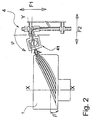
- La figure 2 est une vue suivant la flèche B à la figure 1.

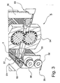
- La figure 3 est un agrandissement montrant plus en détails l'organe visé par la référence 5 à la figure 1.

- La figure 4 est une vue en perspective du même appareil que celui illustré par la figure 1 dans une autre phase de fonctionnement.

- La figure 5 est une vue suivant la flèche C à la figure 4 .

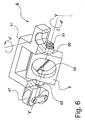
- La figure 6 est un agrandissement montrant plus en détails l'organe visé par la référence 41 à la figure 1.

- Figure 1 shows in perspective an apparatus according to the invention.
- FIG. 2 is a view along arrow B in FIG.
- Figure 3 is an enlargement showing in more detail the member referred to by
reference 5 in Figure 1. - Figure 4 is a perspective view of the same apparatus as that illustrated in Figure 1 in another phase of operation.
- FIG. 5 is a view along the arrow C in FIG.
- Figure 6 is an enlargement showing in more detail the member referred to by
reference 41 in Figure 1.
A la figure 1, on voit une forme 1 sur laquelle on dépose, successivement et dans l'ordre requis par l'architecture du pneumatique, tous les éléments constitutifs de celui-ci. Cette forme 1, sensiblement rigide, peut être par exemple un noyau métallique rigide en plusieurs pièces tel qu'on peut en trouver une description dans la demande de brevet EP 1075928.In Figure 1, we see a shape 1 on which is deposited successively and in the order required by the architecture of the tire, all the constituent elements thereof. This form 1, substantially rigid, may be for example a rigid metal core in several parts such that we can find a description in the patent application EP 1075928.
Le fil 2 de renforcement utilisé est stocké en amont de l'installation, par exemple sur un ensemble de bobines, chacune montée sur un axe faisant partie d'une crémaillère permettant de stocker autant de bobines de fils qu'il y a de fils dans une bandelette. Un dispositif de déroulage de fils 2 (non représenté pour ne pas surcharger le dessin) permet d'entraîner les fils 2 afin de les amener à l'appareil de fabrication d'une structure de renforcement pour pneumatique. De préférence, le dispositif de déroulage de fils 2 comprend autant de moteurs qu'il y a de bobines, chaque moteur permettant d'entraîner un fil 2. Le dispositif de déroulage de fils 2 permet d'entraîner les fils 2 avec une tension bien maîtrisée, par exemple aussi faible que possible.The reinforcing
L'appareil proprement dit comporte essentiellement un assembleur 5 et une tête de pose 4. L'assembleur 5 comporte un orifice d'entrée 51 (voir figure 3) jusqu'auquel les fils 2 cheminent individuellement (les figures 1, 3 et 4 sont schématiques). L'assembleur 5 comporte un orifice d'alimentation 53 permettant d'introduire un ruban 30 d'une composition de caoutchouc cru adaptée à l'usage de la bandelette dans le futur pneumatique. On voit également une bobine 3 sur laquelle est enroulée ledit ruban 30. Le ruban 30 est engagé dans l'orifice d'alimentation 53 de l'assembleur 5. L'assembleur 5 comporte un dispositif de refoulement à caractère volumétrique, à savoir une pompe volumétrique 54.The apparatus itself essentially comprises an
Selon une caractéristique de la présente invention, on contrôle positivement la quantité de composition permettant de fabriquer la bandelette en fonction de la position de la bandelette sur la forme. Dans le mode de réalisation décrit ici, cela se fait en utilisant une pompe mécaniquement volumétrique. La pompe volumétrique 54 est par exemple une pompe à engrenage, comme représenté, ou une pompe à pistons. On trouve la description d'une pompe à pistons dans le brevet US 5 655 891.According to a characteristic of the present invention, the amount of composition making it possible to manufacture the strip is positively controlled as a function of the position of the strip on the shape. In the embodiment described here, this is done using a mechanically volumetric pump. The
Le dispositif de refoulement (appelé ici également « pompe volumétrique 54 ») permet de refouler du caoutchouc cru 30 dans une chambre de formation 50 d'une bandelette 20. L'assembleur 5 comporte un orifice de sortie 52 pour la bandelette 20. L'assembleur 5 comporte deux galets 56 autour desquels la bandelette 20 est enroulée. Au moins un des galets 56 est entraîné en rotation par un moteur 57.The delivery device (also called here "
La tête de pose 4 est monté en regard de la forme 1. Elle comporte un bâti 40, sur lequel est monté un berceau 41 au moyen du mécanisme décrit ci-après. Le berceau 41 est monté via un pivot 42 sur un chariot 43. Grâce au pivot 42, le berceau 41 peut être orienté selon un angle ϕ visible à la figure 6 . La tête de pose 4 comporte également un dispositif de rouletage 49 comportant au moins un galet 47 (deux galets semblables pour une meilleure prise sur la bandelette). Le dispositif de rouletage 49 peut être basculer autour de l'axe YY d'un angle δ. Le dispositif de rouletage 49 permettant d'appliquer la bandelette 20 avec une certaine pression sur la forme 1. Le chariot 43 est monté sur une glissière 44 sensiblement parallèle à l'axe de rotation XX de la forme 1. La glissière 44 est elle-même montée sur deux rails 46 parallèles entre eux, sensiblement perpendiculaires à ladite glissière 44, au moyen de deux coulisseaux 45.The laying
Dans le berceau 41, un cadre 6 est monté sur deux paliers 60. Chacun des paliers 60 comporte une fente 61 centrée sur l'axe des paliers 60. La bandelette 20 peut cheminer au travers des fentes 61 qui organisent un couloir de guidage pour la bandelette 20. Le cadre 6 peut tourner d'au moins 180° par rapport au berceau 41. Le cadre 6 ainsi monté sur le berceau 41 forme un mécanisme de retournement est une réalisation particulière et non limitative d'un dispositif de dépose de ladite bandelette comportant un mécanisme de retournement de la bandelette permettant d'inverser la face de la bandelette qui est amenée au contact de la forme par la tête de pose.In the
Un organe de coupe 48 de la bandelette, tel qu'une guillotine (dont on voit la lame à la figure 6 , la contre-lame étant omise), est intégré au cadre 6, donc à la tête de pose 4.A
La forme 1 est supportée par un porte-moyeu 10, comportant un moyeu auquel la forme 1 et attachée, et comportant la motorisation nécessaire permettant d'entraîner la forme 1 en rotation, à azimut α contrôlé à tout moment. Le bâti 40 est monté fixe par rapport au porte-moyeu 10, au moins pendant le fonctionnement de l'installation (on n'abordera pas ici les aspects d'approche et d'évacuation de la forme 1).The form 1 is supported by a
Le berceau 41 peut être présenté dans toutes les positions voulues par rapport à la forme 1 (voir figures 1, 2, 4 et 5). C'est à dire qu'il peut être déplacé radialement par rapport à la forme 1 (flèche F2), peut coulisser transversalement par rapport à la forme 1 (flèche F1), et peut être incliné autour de l'axe YY (angle δ) par rapport à la forme 1, et orienté selon l'angle ϕ. On peut donc présenter la bandelette 20 à la forme 1 dans toutes les positions souhaitables pour assurer, en combinaison avec la rotation de la forme 1, sa dépose selon toute trajectoire de dépose recherchée.The
Ainsi, on peut déposer la bandelette 20 selon tout angle β par rapport au plan méridien CP, pour former une structure de renforcement selon tout angle β, même variable.Thus, the
On va maintenant décrire le fonctionnement de l'appareil selon l'invention.We will now describe the operation of the apparatus according to the invention.
Selon un aspect particulier de l'invention, l'appareil comporte une unité de contrôle du mouvement de rotation de la forme, du mouvement de la tête par rapport au bâti et de la pompe volumétrique, ladite unité étant configurée de façon à ce que la quantité par unité de longueur de bandelette, de composition engagée à l'intérieur de la chambre de gommage par la pompe volumétrique soit fonction de la position occupée par ladite unité de longueur de bandelette pendant sa dépose sur la forme.According to one particular aspect of the invention, the apparatus comprises a unit for controlling the rotational movement of the shape, of the movement of the head relative to the frame and of the positive displacement pump, said unit being configured so that the quantity per unit strip length, composition engaged within the scrub chamber by the positive displacement pump is a function of the position occupied by said strip length unit during its removal on the form.
Selon un autre aspect particulier de l'invention, l'appareil peut comporter une unité de contrôle du mouvement de rotation de la forme, du mouvement de la tête par rapport au bâti et de la pompe volumétrique, ladite unité étant configurée de façon à ce que le volume, par unité de longueur de bandelette, de composition engagé à l'intérieur de la chambre de gommage par la pompe volumétrique, soit fonction du volume occupé par ladite unité de longueur de bandelette après sa dépose sur la forme.According to another particular aspect of the invention, the apparatus may comprise a unit for controlling the rotational movement of the shape, the movement of the head relative to the frame and the positive displacement pump, said unit being configured so that that the volume, per unit strip length, of composition engaged within the scrub chamber by the positive displacement pump, is a function of the volume occupied by said strip length unit after its removal on the form.
On voit à la figure 1 que la tête de pose 41 se trouve au voisinage de l'épaule droite du futur pneumatique, dont on imagine bien la forme en examinant le noyau rigide 1 sur lequel on va le construire. L'extrémité libre de la bandelette, précédemment coupée en formant un angle β, est présentée à la surface de la forme et y est maintenue par le galet 47, à l'endroit voulu dans la zone d'épaule du futur pneumatique. Bien entendu, la matière contre laquelle on applique la bandelette 20 doit être telle que la bandelette 20 a tendance à rester collée. Typiquement, la forme est déjà revêtue de caoutchouc cru, collant naturellement avec la composition de caoutchouc cru 30.It can be seen in FIG. 1 that the laying
La composition élastomérique est refoulée dans la chambre de formation 50, au moyen du dispositif de refoulement 54. Celui-ci permet d'introduire sous une certaine pression le caoutchouc cru à l'intérieur de la chambre de formation 50, de façon à ce que le caoutchouc la remplisse totalement. Pendant que l'ensemble des fils 2 traverse la chambre de formation 50, un volume de caoutchouc contrôlé est introduit dans la chambre de formation 50. Le paramètre de base pour les asservissements assurés par l'unité de contrôle est la rotation de la forme 1. Par ailleurs, les moyens d'animation de la tête de pose 4 par rapport à la forme 1, dont le fonctionnement est décrit ci-dessous, sont eux-mêmes pilotés de façon à réaliser une certaine trajectoire de dépose en fonction de l'architecture du pneu à fabriquer. On connaît donc à tout moment notamment le rayon auquel la bandelette est déposée, ce qui permet compte tenu de la constitution de la bandelette, elle aussi déterminée par l'architecture du pneumatique, de calculer le volume déposé sur la forme. On connaît aussi le volume occupé par les fils de renforcement en eux-mêmes.The elastomeric composition is discharged into the forming
C'est à partir de la rotation de la forme 1, et compte tenu de sa géométrie connue et des mouvements de la tête de pose 41, et compte tenu de l'encours (stock de bandelette existant entre la chambre de formation 50 et l'endroit où la bandelette rejoint la forme 1), que l'unité de contrôle détermine donc le volume de caoutchouc à introduire dans la chambre de formation 50. En même temps, les fils 2 entraînent ce même volume de caoutchouc hors de la chambre de formation 50. Ainsi, la bandelette 20 apparaissant à l'orifice d'extrusion 52 comporte l'ensemble des fils 2 déroulés en parallèle et une quantité bien maîtrisée de caoutchouc d'imprégnation 30. La bandelette 20 est elle-même motorisée au moyen des galets 56 et du moteur 57 de façon à ce qu'elle soit entraînée hors de la chambre 50 avec une tension sensiblement constante.It is from the rotation of the form 1, and taking into account its known geometry and the movements of the laying
On voit une zone de compensation, interposée entre l'assembleur 5 et le dispositif de pose 4, dans laquelle une certaine longueur (connue) de bandelette est accumulée. Cela permet d'assurer sans heurt le fonctionnement essentiellement continu de l'assembleur 5 et le fonctionnement essentiellement discontinu de la tête de pose 41, et permet donc de lisser la formation de bandelette par rapport aux variations de vitesse de la forme 1, dont on a dit ci-dessus qu'il s'agit d'un paramètre de base du pilotage assuré par l'unité de contrôle.We see a compensation zone, interposed between the
Afin de pouvoir éviter les effets néfastes de dérive du fonctionnement, il est avantageux de mesurer la longueur de bandelette réellement utilisée, indépendamment des paramètres d'asservissement qui calculent en permanence la longueur de bandelette à fabriquer. Un galet de mesure, de préférence indépendant du ou des galets 47 (non représenté) est équipé d'un codeur qui permet de connaître à tout moment et avec précision la longueur de bandelette déposée sur la forme 1. Ceci permet d'ajuster la fabrication de bandelette à la quantité de bandelette effectivement déposée sur la forme 1.In order to be able to avoid the harmful effects of drift in operation, it is advantageous to measure the length of the strip actually used, independently of the servo parameters which continuously calculate the length of strip to be manufactured. A measuring roller, preferably independent of the roller or rollers 47 (not shown) is equipped with an encoder which makes it possible to know at any time and with precision the length of the strip deposited on the shape 1. This makes it possible to adjust the manufacture of the strip to the quantity of strip actually deposited on the form 1.
Le noyau 1 est entraîné en rotation (angle α) et le berceau 41 est mobile par rapport à la forme. Le berceau 41 est translaté de droite vers la gauche (flèche F1) pour rejoindre la position où elle est dessinée en traits interrompus, tout ceci de façon synchrone. Pendant que le berceau 41 se déplace sur une largeur qui correspond à la largeur de la structure de renforcement fabriquée sous la bande de roulement du pneumatique, le noyau 1 est entraîné en rotation de façon à parcourir un arc α. Pendant ces mouvements, la bandelette 20 est appliquée sur la forme 1 par le galet de rouletage 47. Vers la fin de ces mouvements, la guillotine intégrée à la tête de pose sectionne la bandelette tout en respectant l'angle que l'on souhaite donner au bord de la bandelette. Cet angle correspond à l'angle que doit former le bord du tronçon suivant. Il n'y a donc aucune perte de matière entre deux tronçons successifs.The core 1 is rotated (angle α) and the
Afin de permettre le fonctionnement automatique, la bandelette est en permanence en prise dans la tête de pose 4. Un dispositif d'avance automatique (non représenté) de la bandelette après coupe permet que son extrémité libre soit à nouveau en prise avec le dispositif de rouletage 49 après la coupe, afin de pouvoir à nouveau être présentée à la forme 1 et pressée sur celle-ci. L'unité de contrôle connaît en permanence la longueur de bandelette accumulée et non posée, ce qui permet de tenir compte de cet encours dans le contrôle volumétrique de la quantité unitaire de composition par longueur unitaire de bandelette.In order to allow automatic operation, the strip is permanently engaged in the laying
De proche en proche, on dépose sur la forme le nombre voulu de tronçons de bandelette de façon par exemple adjacente, en recouvrant progressivement toute la périphérie de la forme de fabrication. De part la formation de la bandelette telle qu'elle est décrite ici, le pas entre tous les fils est constant dans la bandelette. Au final, on peut au choix s'arranger de façon à maintenir le même pas ou un pas différent entre les fils adjacents issus de deux bandelettes différentes.Gradually, the desired number of stretcher strip sections is deposited on the shape, for example adjacent, progressively covering the entire periphery of the form of manufacture. Due to the formation of the strip as described here, the pitch between all the threads is constant in the strip. In the end, one can choose to arrange so as to maintain the same step or a different step between the adjacent son from two different strips.
L'opération de dépose des tronçons de bandelette 20 peut entraîner autant de tours complets de la forme 1 qu'il y a de tronçons de bandelettes pour réaliser une structure de renforcement complète ou bien, dès que la tête de pose rejoint l'épaule gauche du futur pneumatique, elle peut être ramenée à l'épaule opposée sans interrompre la rotation de la forme 1 et un autre tronçon de bandelette peut être déposé dès que la tête de pose a rejoint l'épaule droite. Il suffit de s'arranger pour laisser un espace entre les deux tronçons posés correspondant à un nombre entier de tronçons qui seront installés au cours de rotations successives.The operation of removing
Pour passer d'une couche à la couche suivante (on appelle cela également pour passer d'une nappe à la nappe suivante), selon une caractéristique avantageuse de la présente invention, un dispositif de retournement est intégré à la tête de pose. Il suffit de faire pivoter le cadre 6 de 180° et la bandelette 20 est prête à effectuer la dépose de la couche suivante. On reprend alors les mouvements exposés ci-dessus, à ceci près que l'on agit de gauche à droite au lieu de travailler de droite vers la gauche. C'est ce que l'on a représenté à la figure 4 .To pass from one layer to the next layer (this is also called to go from one sheet to the next sheet), according to an advantageous characteristic of the present invention, a turning device is integrated with the laying head. Just rotate the frame 6 180 ° and the
Dans une application particulière, l'invention permet de fabriquer une structure de renforcement comportant de multiples arceaux de fils obtenus en déposant successivement des tronçons de bandelette adjacents créés par coupe de la bandelette. Dans un cas plus particulier encore, ladite structure de renforcement fait partie d'une ceinture située sous la bande de roulement. Dans un autre cas plus particulier, ladite structure de renforcement fait partie d'une carcasse allant jusqu'à un bourrelet au moins.In a particular application, the invention makes it possible to manufacture a reinforcement structure comprising multiple arches of threads obtained by successively depositing strips of adjacent strips created by cutting the strip. In a still more particular case, said reinforcing structure is part of a belt located under the tread. In another more particular case, said reinforcing structure is part of a carcass up to at least one bead.
L'invention permet de déposer les fils de renforcement par groupes formant une bandelette avec une précision de pose bien meilleure que ce que proposait l'état de la technique jusqu'à présent pour les techniques de fabrication à partir de bandelettes. Par ailleurs, grâce au dispositif de retournement de bandelette proposé par la présente invention, le passage d'une couche à une autre avec changement d'angle formé par les fils de renforcement peut se faire extrêmement rapidement, sans ralentir en aucune façon la cadence de fabrication d'un appareil selon l'invention, et sans perte de matière.The invention makes it possible to deposit the reinforcing threads in groups forming a strip with a laying accuracy which is much better than that proposed by the state of the art so far for manufacturing techniques from strips. Moreover, thanks to the tape reversing device proposed by the present invention, the passage from one layer to another with a change of angle formed by the reinforcing son can be done extremely rapidly, without slowing down in any way the rate of manufacture of an apparatus according to the invention, and without loss of material.
Claims (13)
- Method of manufacturing a tyre comprising a reinforcement structure comprising threads disposed substantially parallel to each other, the method using a substantially toroidal form(1) on which the said reinforcement structure is progressively constructed, the method comprising the following steps:wherein, in order to form a unit length of strip, a unit quantity of the said composition is used, determined according to the share taken by the said unit length of strip after its deposition on the form during the manufacture of the tyre.• in situ forming a group of several threads (2) disposed substantially parallel to each other,• in situ joining the threads by means of an elastomeric composition in order to form a strip (20),• in situ cutting the said strip into successive portions• depositing successively the said portions of said strip along a predetermined trajectory on the surface of the said form,
- Method according to Claim 1, in which the unit quantity used is obtained by means of a volumetric control, the share taken being estimated according to the volume occupied by the said unit length.
- Method according to Claim 1 or 2, wherein a strip with a constant cross-section is formed, and wherein the said volume occupied by the unit length is determined according to the radius of deposition on the surface of the form and the angle of the arc occupied by the unit length on the surface of the form.
- Method according to one of Claims 1 to 3, wherein the strip is formed by members disposed at a fixed position in space, and in which the strip is then brought to a laying head, at least one laying outlet of which is able to move with respect to the form, and in which the said unit quantity is controlled by taking account of the length of the strip accumulated between the formation of the strip and the laying head.
- Method according to Claim 4, wherein the progressive construction of the reinforcement structure takes place whilst the said form is in rotation, by moving the laying head in a plane comprising the axis of rotation of the form, the control of the unit quantity being controlled by the rotation of the form.
- Method according to one of Claims 1 to 5, wherein, in order to join the threads by means of an elastomeric composition, the said threads are introduced in parallel into an assembler comprising a formation chamber inside which the said composition is delivered, the assembler comprising an outlet orifice for the strip.
- Method according to one of Claims 1 to 6, wherein the said reinforcement structure comprises many arches of threads obtained by successively depositing adjacent portions of strip.
- Method according to one of Claims 1 to 7, wherein the said reinforcement structure forms part of a belt situated underneath the tread.
- Method according to one of Claims 1 to 7, wherein the said reinforcement structure forms part of a carcass.
- Apparatus for fabricating a reinforcement structure for a tyre, the said reinforcement structure comprising threads disposed substantially parallel to each other, the said apparatus being intended to be used in cooperation with a substantially toroidal form (1) on which the said reinforcement structure is progressively constructed by depositing arches of the said thread side by side along a desired trajectory for the said thread on the surface of the said form, the said apparatus comprising:• an assembler (5) comprising an entry for receiving the threads (2), a rubber coating chamber (50), a volumetric pump for delivering an elastomeric composition inside the chamber, an exit orifice for a strip (20) comprising the threads joined by the said composition,• a member (48) for cutting the strip into successive portions,• a device (4) for depositing the said successive portions of said strip onto the form comprising a reference framework with respect to which the said form can be installed at a known position, the depositing device comprising a head equipped with a guidance passage for the strip and a rolling-down member intended to cooperate with the said form and a mechanism for turning over the strip making it possible to invert the face of the strip which is brought in contact with the form by the laying head, the apparatus comprising at least one actuator for guiding the said head with respect to the reference framework.
- Apparatus according to Claim 10, comprising a unit for controlling the rotation movement of the form and the movement of the head with respect to the framework and the volumetric pump, the said unit being configured so that the quantity, per unit length of strip, of composition inserted inside the chamber by the volumetric pump is a function of the position occupied by the said unit length of strip during its deposition on the form.
- Apparatus according to Claim 10, comprising a unit for controlling the rotation movement of the form and the movement of the head with respect to the framework and the volumetric pump, the said unit being configured so that the volume, per unit length of strip, of composition inserted inside the chamber by the volumetric pump is a function of the volume occupied by the said unit length of strip after its deposition on the form.
- Apparatus according to Claim 10, comprising a strip length compensation area, disposed between the assembler (5) and the depositing device (4).
Applications Claiming Priority (3)
| Application Number | Priority Date | Filing Date | Title |
|---|---|---|---|
| FR0206822 | 2002-06-03 | ||
| FR0206822 | 2002-06-03 | ||
| PCT/EP2003/005625 WO2003101714A2 (en) | 2002-06-03 | 2003-05-28 | System for producing a reinforcing structure for a tyre with volumetric control of the die |
Publications (2)
| Publication Number | Publication Date |
|---|---|
| EP1513672A2 EP1513672A2 (en) | 2005-03-16 |
| EP1513672B1 true EP1513672B1 (en) | 2007-04-04 |
Family
ID=29595148
Family Applications (1)
| Application Number | Title | Priority Date | Filing Date |
|---|---|---|---|
| EP03732489A Expired - Lifetime EP1513672B1 (en) | 2002-06-03 | 2003-05-28 | System for producing a reinforcing structure for a tyre with volumetric control of the die |
Country Status (9)
| Country | Link |
|---|---|
| US (1) | US7399374B2 (en) |
| EP (1) | EP1513672B1 (en) |
| JP (1) | JP4637575B2 (en) |
| CN (1) | CN100408320C (en) |
| AT (1) | ATE358570T1 (en) |
| AU (1) | AU2003238423A1 (en) |
| BR (1) | BR0304965A (en) |
| DE (1) | DE60312983T2 (en) |
| WO (1) | WO2003101714A2 (en) |
Families Citing this family (11)
| Publication number | Priority date | Publication date | Assignee | Title |
|---|---|---|---|---|
| US20040154727A1 (en) * | 2003-02-11 | 2004-08-12 | Weissert James Thomas | Method and apparatus for manufacturing carcass plies for a tire |
| JP4346436B2 (en) * | 2003-12-25 | 2009-10-21 | 横浜ゴム株式会社 | Pneumatic tire and manufacturing method thereof |
| JP4500075B2 (en) * | 2004-03-22 | 2010-07-14 | 住友ゴム工業株式会社 | Pneumatic tire |
| KR101202791B1 (en) * | 2005-05-30 | 2012-11-19 | 피렐리 타이어 소시에떼 퍼 아찌오니 | Method for Manufacturing a Tyre and Apparatus for Laying a Reinforcing Element on a Forming Support |
| JP4753649B2 (en) * | 2005-07-26 | 2011-08-24 | 株式会社ブリヂストン | Manufacturing method and manufacturing apparatus of tire constituent member. |
| JP2012513334A (en) * | 2008-12-22 | 2012-06-14 | ピレリ・タイヤ・ソチエタ・ペル・アツィオーニ | Two-wheeled vehicle tire and manufacturing method thereof |
| RU2505398C2 (en) * | 2011-12-07 | 2014-01-27 | Федеральное государственное бюджетное образовательное учреждение высшего профессионального образования "Братский государственный университет" | Method of reinforcing automotive tires with resilient spokes and female die for wheel production |
| US10307980B2 (en) | 2013-02-20 | 2019-06-04 | The Goodyear Tire & Rubber Company | Tire building applicator members and systems |
| KR101741224B1 (en) * | 2015-05-08 | 2017-05-30 | 주식회사 한성시스코 | textile cord counting apparatus for tire jointless reinforced belt |
| JP6993872B2 (en) * | 2017-12-28 | 2022-01-14 | Toyo Tire株式会社 | How to manufacture tire belts |
| JP2022134774A (en) * | 2021-03-04 | 2022-09-15 | 横浜ゴム株式会社 | Method for manufacturing tire and molding apparatus |
Family Cites Families (30)
| Publication number | Priority date | Publication date | Assignee | Title |
|---|---|---|---|---|
| US1728957A (en) | 1923-03-16 | 1929-09-24 | Dickinson Cord Tire Corp | Cord-tire-making machine |
| GB987983A (en) * | 1961-03-08 | 1965-03-31 | Dunlop Rubber Co | Improvements in or relating to the manufacture of pneumatic tyres |
| US3770042A (en) | 1970-09-03 | 1973-11-06 | Deering Milliken Res Corp | Endless reinforcement and method for producing same |
| US3761341A (en) | 1971-04-12 | 1973-09-25 | Deering Milliken Res Corp | Apparatus for guiding a strip to a support surface |
| FR2599297B1 (en) | 1986-06-02 | 1988-08-12 | Michelin & Cie | PROCESS AND MACHINE FOR MANUFACTURING A REINFORCEMENT FOR TIRES |
| FR2603841B1 (en) * | 1986-09-17 | 1989-02-24 | Michelin & Cie | METHOD OF MANUFACTURING A TIRE WITH LAYING RUBBER PRODUCTS AND REINFORCING ELEMENTS ON A SUPPORT, DEVICE FOR LAYING RUBBER PRODUCTS AND MACHINE USING SUCH DEVICE (S) |
| US5221406A (en) * | 1986-09-17 | 1993-06-22 | Compagnie Generale Des Etablissements Michelin | Apparatus for manufacturing a tire by the laying of rubber products onto a rotating core |
| JPH04191101A (en) * | 1990-11-26 | 1992-07-09 | Sumitomo Rubber Ind Ltd | Tire for aircraft |
| US5156781A (en) * | 1990-12-24 | 1992-10-20 | Bridgestone Corporation | Compact precision extrusion method |
| EP0557615A1 (en) * | 1992-01-23 | 1993-09-01 | Bridgestone Corporation | Method and apparatus for forming cord reinforced elastomeric strips |
| FR2721662A1 (en) | 1994-06-28 | 1995-12-29 | Sedepro | Positive displacement pump. |
| GB9603948D0 (en) * | 1996-02-24 | 1996-04-24 | Sumitomo Rubber Ind | Reinforcement ply and method of manufacture |
| JPH09254274A (en) * | 1996-03-21 | 1997-09-30 | Bridgestone Corp | Production method and device for green tire for retreading |
| JPH10296873A (en) * | 1997-04-24 | 1998-11-10 | Yokohama Rubber Co Ltd:The | Method and device for molding belt layer of pneumatic tire |
| DE19718699C1 (en) * | 1997-05-02 | 1998-05-28 | Continental Ag | Tyre building process to give tread with a path for discharge of static electricity |
| EP0956940B1 (en) * | 1997-10-03 | 2003-04-02 | Bridgestone Corporation | Apparatus for forming a tire reinforcing layer. |
| EP0943421B1 (en) * | 1997-11-28 | 2003-05-28 | Pirelli Pneumatici Societa' Per Azioni | A method for making tyres for vehicle wheels |
| ATE233665T1 (en) * | 1997-11-28 | 2003-03-15 | Pirelli | AIR TIRES FOR VEHICLE WHEELS |
| JP4420491B2 (en) * | 1998-06-29 | 2010-02-24 | 株式会社ブリヂストン | Method and apparatus for attaching rubber material for tire component |
| DE19831747A1 (en) * | 1998-07-15 | 2000-01-20 | Continental Ag | Building vehicle tire by winding-on strips of rubber for sidewalls, tread and belt reinforcements employs continuous extrusion with forming rolls, enabling two-stage vulcanization and incorporation of antistatic structure |
| ES2184371T3 (en) * | 1998-07-31 | 2003-04-01 | Pirelli | MANUFACTURING PROCEDURE OF A HARMZON FOR TIRES AND ARMAZON AS OBTAINED. |
| CN1262410C (en) * | 1998-10-02 | 2006-07-05 | 米凯林技术研究公司 | Tyre with directly applied tread sizing material on radial outer reinforced layer |
| JP4358350B2 (en) | 1999-04-19 | 2009-11-04 | 株式会社ブリヂストン | Method and apparatus for forming tire reinforcing layer |
| DE69939402D1 (en) * | 1999-05-14 | 2008-10-02 | Michelin Soc Tech | REINFORCING BELT FOR A RADIAL TIRE |
| DE60009991T2 (en) | 1999-08-10 | 2005-03-31 | Sedepro | Stiff core for the manufacture of pneumatic tires containing a mounting rim |
| JP2001088225A (en) * | 1999-09-21 | 2001-04-03 | Bridgestone Corp | Method and apparatus for producing tire constituting belt |
| JP4326112B2 (en) * | 2000-04-10 | 2009-09-02 | 株式会社ブリヂストン | Manufacturing method of tire carcass |
| US6849146B2 (en) | 2000-10-25 | 2005-02-01 | Toyo Tire & Rubber Co., Ltd. | Carcass ply producing apparatus, carcass ply producing method and pneumatic tire |
| JP2002160284A (en) * | 2000-11-22 | 2002-06-04 | Bridgestone Corp | Method for extruding rubber material for tire and extrusion device |
| WO2002055289A1 (en) | 2001-01-12 | 2002-07-18 | Bridgestone Corporation | Tire construction member producing method and device therefor |
-
2003
- 2003-05-28 DE DE60312983T patent/DE60312983T2/en not_active Expired - Lifetime
- 2003-05-28 AT AT03732489T patent/ATE358570T1/en not_active IP Right Cessation
- 2003-05-28 CN CNB038128365A patent/CN100408320C/en not_active Expired - Fee Related
- 2003-05-28 EP EP03732489A patent/EP1513672B1/en not_active Expired - Lifetime
- 2003-05-28 JP JP2004509042A patent/JP4637575B2/en not_active Expired - Fee Related
- 2003-05-28 BR BR0304965-5A patent/BR0304965A/en not_active Application Discontinuation
- 2003-05-28 AU AU2003238423A patent/AU2003238423A1/en not_active Abandoned
- 2003-05-28 WO PCT/EP2003/005625 patent/WO2003101714A2/en active IP Right Grant
-
2004
- 2004-12-02 US US11/000,930 patent/US7399374B2/en not_active Expired - Fee Related
Also Published As
| Publication number | Publication date |
|---|---|
| CN1659016A (en) | 2005-08-24 |
| US7399374B2 (en) | 2008-07-15 |
| WO2003101714A2 (en) | 2003-12-11 |
| WO2003101714A8 (en) | 2005-01-20 |
| US20080000574A9 (en) | 2008-01-03 |
| CN100408320C (en) | 2008-08-06 |
| US20050076993A1 (en) | 2005-04-14 |
| JP4637575B2 (en) | 2011-02-23 |
| EP1513672A2 (en) | 2005-03-16 |
| WO2003101714A3 (en) | 2004-09-23 |
| BR0304965A (en) | 2004-09-28 |
| AU2003238423A8 (en) | 2003-12-19 |
| DE60312983D1 (en) | 2007-05-16 |
| ATE358570T1 (en) | 2007-04-15 |
| AU2003238423A1 (en) | 2003-12-19 |
| DE60312983T2 (en) | 2007-12-13 |
| JP2005528258A (en) | 2005-09-22 |
Similar Documents
| Publication | Publication Date | Title |
|---|---|---|
| EP1517781B1 (en) | Device for producing a reinforcing structure for a tyre, comprising a strip turning mechanism | |
| EP0582215B1 (en) | Method for manufacturing tires and apparatus for manufacturing a crown reinforcement for tires | |
| EP0248301B1 (en) | Method and apparatus for making a reinforcement for a tyre | |
| EP0519294B1 (en) | Method for the production of a tyre and machine for implementing the method | |
| EP1513672B1 (en) | System for producing a reinforcing structure for a tyre with volumetric control of the die | |
| EP1838520A1 (en) | Method and device for manufacturing and placing a circumferential reinforcement for a tyre and tyre obtained according to said process | |
| EP0519295B1 (en) | Method for the production of a tyre and apparatus for the implementation of the method | |
| EP1147864B1 (en) | High speed cutting device for cutting reinforcing elements for tyres | |
| EP2613928B1 (en) | Process and device for building a green pneumatic tire by means of a strip | |
| EP1590169B1 (en) | Apparatus for producing a tire reinforcement provided with a device for guiding the reinforcing wire and method of manufacturing a tire reinforcement using such an apparatus. | |
| EP0366773B1 (en) | Process and, device for applying a rubber coating on wires unwound in parallel to produce a sheet | |
| EP1426169B1 (en) | Apparatus for the manufacture of a reinforcing element for large-dimension tyres | |
| EP1279484B1 (en) | Method and Apparatus for the manufacture of a reinforcing structure for a tyre | |
| EP1824666B1 (en) | Appliance for producing a reinforcement for a pneumatic tyre | |
| EP0704295B1 (en) | Wire reinforcement of a rubber matrix |
Legal Events
| Date | Code | Title | Description |
|---|---|---|---|
| PUAI | Public reference made under article 153(3) epc to a published international application that has entered the european phase |
Free format text: ORIGINAL CODE: 0009012 |
|
| AK | Designated contracting states |
Kind code of ref document: A2 Designated state(s): AT BE BG CH CY CZ DE DK EE ES FI FR GB GR HU IE IT LI LU MC NL PT RO SE SI SK TR |
|
| AX | Request for extension of the european patent |
Extension state: AL LT LV MK |
|
| 17P | Request for examination filed |
Effective date: 20050323 |
|
| DAX | Request for extension of the european patent (deleted) | ||
| GRAP | Despatch of communication of intention to grant a patent |
Free format text: ORIGINAL CODE: EPIDOSNIGR1 |
|
| GRAS | Grant fee paid |
Free format text: ORIGINAL CODE: EPIDOSNIGR3 |
|
| GRAA | (expected) grant |
Free format text: ORIGINAL CODE: 0009210 |
|
| AK | Designated contracting states |
Kind code of ref document: B1 Designated state(s): AT BE BG CH CY CZ DE DK EE ES FI FR GB GR HU IE IT LI LU MC NL PT RO SE SI SK TR |
|
| PG25 | Lapsed in a contracting state [announced via postgrant information from national office to epo] |
Ref country code: SI Free format text: LAPSE BECAUSE OF FAILURE TO SUBMIT A TRANSLATION OF THE DESCRIPTION OR TO PAY THE FEE WITHIN THE PRESCRIBED TIME-LIMIT Effective date: 20070404 Ref country code: FI Free format text: LAPSE BECAUSE OF FAILURE TO SUBMIT A TRANSLATION OF THE DESCRIPTION OR TO PAY THE FEE WITHIN THE PRESCRIBED TIME-LIMIT Effective date: 20070404 |
|
| REG | Reference to a national code |
Ref country code: GB Ref legal event code: FG4D Free format text: NOT ENGLISH |
|
| REG | Reference to a national code |
Ref country code: CH Ref legal event code: EP |
|
| REF | Corresponds to: |
Ref document number: 60312983 Country of ref document: DE Date of ref document: 20070516 Kind code of ref document: P |
|
| REG | Reference to a national code |
Ref country code: IE Ref legal event code: FG4D Free format text: LANGUAGE OF EP DOCUMENT: FRENCH |
|
| PG25 | Lapsed in a contracting state [announced via postgrant information from national office to epo] |
Ref country code: SE Free format text: LAPSE BECAUSE OF FAILURE TO SUBMIT A TRANSLATION OF THE DESCRIPTION OR TO PAY THE FEE WITHIN THE PRESCRIBED TIME-LIMIT Effective date: 20070704 |
|
| PG25 | Lapsed in a contracting state [announced via postgrant information from national office to epo] |
Ref country code: ES Free format text: LAPSE BECAUSE OF FAILURE TO SUBMIT A TRANSLATION OF THE DESCRIPTION OR TO PAY THE FEE WITHIN THE PRESCRIBED TIME-LIMIT Effective date: 20070715 |
|
| PG25 | Lapsed in a contracting state [announced via postgrant information from national office to epo] |
Ref country code: PT Free format text: LAPSE BECAUSE OF FAILURE TO SUBMIT A TRANSLATION OF THE DESCRIPTION OR TO PAY THE FEE WITHIN THE PRESCRIBED TIME-LIMIT Effective date: 20070904 |
|
| NLV1 | Nl: lapsed or annulled due to failure to fulfill the requirements of art. 29p and 29m of the patents act | ||
| GBV | Gb: ep patent (uk) treated as always having been void in accordance with gb section 77(7)/1977 [no translation filed] |
Effective date: 20070404 |
|
| PG25 | Lapsed in a contracting state [announced via postgrant information from national office to epo] |
Ref country code: AT Free format text: LAPSE BECAUSE OF FAILURE TO SUBMIT A TRANSLATION OF THE DESCRIPTION OR TO PAY THE FEE WITHIN THE PRESCRIBED TIME-LIMIT Effective date: 20070404 |
|
| REG | Reference to a national code |
Ref country code: IE Ref legal event code: FD4D |
|
| BERE | Be: lapsed |
Owner name: MICHELIN RECHERCHE ET TECHNIQUE S.A. Effective date: 20070531 Owner name: SOC. DE TECHNOLOGIE MICHELIN Effective date: 20070531 |
|
| REG | Reference to a national code |
Ref country code: CH Ref legal event code: PL |
|
| PG25 | Lapsed in a contracting state [announced via postgrant information from national office to epo] |
Ref country code: MC Free format text: LAPSE BECAUSE OF NON-PAYMENT OF DUE FEES Effective date: 20070531 Ref country code: BG Free format text: LAPSE BECAUSE OF FAILURE TO SUBMIT A TRANSLATION OF THE DESCRIPTION OR TO PAY THE FEE WITHIN THE PRESCRIBED TIME-LIMIT Effective date: 20070704 Ref country code: CZ Free format text: LAPSE BECAUSE OF FAILURE TO SUBMIT A TRANSLATION OF THE DESCRIPTION OR TO PAY THE FEE WITHIN THE PRESCRIBED TIME-LIMIT Effective date: 20070404 Ref country code: IE Free format text: LAPSE BECAUSE OF FAILURE TO SUBMIT A TRANSLATION OF THE DESCRIPTION OR TO PAY THE FEE WITHIN THE PRESCRIBED TIME-LIMIT Effective date: 20070404 Ref country code: DK Free format text: LAPSE BECAUSE OF FAILURE TO SUBMIT A TRANSLATION OF THE DESCRIPTION OR TO PAY THE FEE WITHIN THE PRESCRIBED TIME-LIMIT Effective date: 20070404 Ref country code: NL Free format text: LAPSE BECAUSE OF FAILURE TO SUBMIT A TRANSLATION OF THE DESCRIPTION OR TO PAY THE FEE WITHIN THE PRESCRIBED TIME-LIMIT Effective date: 20070404 |
|
| PLBE | No opposition filed within time limit |
Free format text: ORIGINAL CODE: 0009261 |
|
| STAA | Information on the status of an ep patent application or granted ep patent |
Free format text: STATUS: NO OPPOSITION FILED WITHIN TIME LIMIT |
|
| PG25 | Lapsed in a contracting state [announced via postgrant information from national office to epo] |
Ref country code: SK Free format text: LAPSE BECAUSE OF FAILURE TO SUBMIT A TRANSLATION OF THE DESCRIPTION OR TO PAY THE FEE WITHIN THE PRESCRIBED TIME-LIMIT Effective date: 20070404 Ref country code: LI Free format text: LAPSE BECAUSE OF NON-PAYMENT OF DUE FEES Effective date: 20070531 Ref country code: CH Free format text: LAPSE BECAUSE OF NON-PAYMENT OF DUE FEES Effective date: 20070531 |
|
| 26N | No opposition filed |
Effective date: 20080107 |
|
| PG25 | Lapsed in a contracting state [announced via postgrant information from national office to epo] |
Ref country code: BE Free format text: LAPSE BECAUSE OF NON-PAYMENT OF DUE FEES Effective date: 20070531 |
|
| PG25 | Lapsed in a contracting state [announced via postgrant information from national office to epo] |
Ref country code: GB Free format text: LAPSE BECAUSE OF FAILURE TO SUBMIT A TRANSLATION OF THE DESCRIPTION OR TO PAY THE FEE WITHIN THE PRESCRIBED TIME-LIMIT Effective date: 20070404 Ref country code: GR Free format text: LAPSE BECAUSE OF FAILURE TO SUBMIT A TRANSLATION OF THE DESCRIPTION OR TO PAY THE FEE WITHIN THE PRESCRIBED TIME-LIMIT Effective date: 20070705 |
|
| PG25 | Lapsed in a contracting state [announced via postgrant information from national office to epo] |
Ref country code: RO Free format text: LAPSE BECAUSE OF FAILURE TO SUBMIT A TRANSLATION OF THE DESCRIPTION OR TO PAY THE FEE WITHIN THE PRESCRIBED TIME-LIMIT Effective date: 20070404 |
|
| PG25 | Lapsed in a contracting state [announced via postgrant information from national office to epo] |
Ref country code: EE Free format text: LAPSE BECAUSE OF FAILURE TO SUBMIT A TRANSLATION OF THE DESCRIPTION OR TO PAY THE FEE WITHIN THE PRESCRIBED TIME-LIMIT Effective date: 20070404 |
|
| PG25 | Lapsed in a contracting state [announced via postgrant information from national office to epo] |
Ref country code: CY Free format text: LAPSE BECAUSE OF FAILURE TO SUBMIT A TRANSLATION OF THE DESCRIPTION OR TO PAY THE FEE WITHIN THE PRESCRIBED TIME-LIMIT Effective date: 20070404 |
|
| PG25 | Lapsed in a contracting state [announced via postgrant information from national office to epo] |
Ref country code: LU Free format text: LAPSE BECAUSE OF NON-PAYMENT OF DUE FEES Effective date: 20070528 |
|
| PG25 | Lapsed in a contracting state [announced via postgrant information from national office to epo] |
Ref country code: TR Free format text: LAPSE BECAUSE OF FAILURE TO SUBMIT A TRANSLATION OF THE DESCRIPTION OR TO PAY THE FEE WITHIN THE PRESCRIBED TIME-LIMIT Effective date: 20070404 Ref country code: HU Free format text: LAPSE BECAUSE OF FAILURE TO SUBMIT A TRANSLATION OF THE DESCRIPTION OR TO PAY THE FEE WITHIN THE PRESCRIBED TIME-LIMIT Effective date: 20071005 |
|
| REG | Reference to a national code |
Ref country code: FR Ref legal event code: PLFP Year of fee payment: 14 |
|
| REG | Reference to a national code |
Ref country code: FR Ref legal event code: PLFP Year of fee payment: 15 |
|
| REG | Reference to a national code |
Ref country code: FR Ref legal event code: PLFP Year of fee payment: 16 |
|
| PGFP | Annual fee paid to national office [announced via postgrant information from national office to epo] |
Ref country code: DE Payment date: 20180522 Year of fee payment: 16 |
|
| PGFP | Annual fee paid to national office [announced via postgrant information from national office to epo] |
Ref country code: IT Payment date: 20180530 Year of fee payment: 16 Ref country code: FR Payment date: 20180522 Year of fee payment: 16 |
|
| REG | Reference to a national code |
Ref country code: DE Ref legal event code: R119 Ref document number: 60312983 Country of ref document: DE |
|
| PG25 | Lapsed in a contracting state [announced via postgrant information from national office to epo] |
Ref country code: IT Free format text: LAPSE BECAUSE OF NON-PAYMENT OF DUE FEES Effective date: 20190528 Ref country code: DE Free format text: LAPSE BECAUSE OF NON-PAYMENT OF DUE FEES Effective date: 20191203 |
|
| PG25 | Lapsed in a contracting state [announced via postgrant information from national office to epo] |
Ref country code: FR Free format text: LAPSE BECAUSE OF NON-PAYMENT OF DUE FEES Effective date: 20190531 |