EP1464402A2 - Aufnahmebehälter für rasterförmig angeordnete Laborgegenstände, insbesondere Pipettenspitzen - Google Patents
Aufnahmebehälter für rasterförmig angeordnete Laborgegenstände, insbesondere Pipettenspitzen Download PDFInfo
- Publication number
- EP1464402A2 EP1464402A2 EP04005935A EP04005935A EP1464402A2 EP 1464402 A2 EP1464402 A2 EP 1464402A2 EP 04005935 A EP04005935 A EP 04005935A EP 04005935 A EP04005935 A EP 04005935A EP 1464402 A2 EP1464402 A2 EP 1464402A2
- Authority
- EP
- European Patent Office
- Prior art keywords
- receptacle
- cover
- lid
- opening
- movement
- Prior art date
- Legal status (The legal status is an assumption and is not a legal conclusion. Google has not performed a legal analysis and makes no representation as to the accuracy of the status listed.)
- Withdrawn
Links
Images


Classifications
-
- B—PERFORMING OPERATIONS; TRANSPORTING
- B01—PHYSICAL OR CHEMICAL PROCESSES OR APPARATUS IN GENERAL
- B01L—CHEMICAL OR PHYSICAL LABORATORY APPARATUS FOR GENERAL USE
- B01L9/00—Supporting devices; Holding devices
- B01L9/54—Supports specially adapted for pipettes and burettes
- B01L9/543—Supports specially adapted for pipettes and burettes for disposable pipette tips, e.g. racks or cassettes
-
- B—PERFORMING OPERATIONS; TRANSPORTING
- B01—PHYSICAL OR CHEMICAL PROCESSES OR APPARATUS IN GENERAL
- B01L—CHEMICAL OR PHYSICAL LABORATORY APPARATUS FOR GENERAL USE
- B01L2300/00—Additional constructional details
- B01L2300/04—Closures and closing means
- B01L2300/041—Connecting closures to device or container
- B01L2300/045—Connecting closures to device or container whereby the whole cover is slidable
Definitions
- the invention relates to a receptacle for preferably grid-shaped arranged laboratory objects, in particular for pipette tips, test tubes and reaction vessels, with an the open top from which the Laboratory objects are accessible from the top, closing lid, according to the preamble of claim 1 or the subordinate Claims 3 and 7.
- Receptacles of the type in question are as pipette boxes or Autoclave boxes have been known for a long time.
- Laboratory objects such as pipette tips, Reaction tubes, sample tubes etc. are made in chemical, biological and medical laboratories extensively used.
- pipette tips are used in large quantities. They make work easier arranged in a grid in autoclave boxes.
- Grid arrangements are common 12 x 8 or 10 x 6, which doesn't rule out that too other grid arrangements in the same or unequal ratio are known and of course are easily possible.
- the grid-like arrangement the pipette tips have the advantage that multiple pipettes are used can.
- such a grid is useful, because even with multichannel pipettes of the appropriate dimensions can be.
- Receptacles of the type in question are available with a sliding lid and with hinged lid.
- a known construction with sliding cover (DE 195 25 258 A1) shows a sliding cover with one each in a first embodiment Pair of guides on the top and bottom.
- This Sliding lid can be used on the associated receptacle depending on the use a twelve-channel or an eight-channel multichannel pipette into the then suitable guides are pushed onto the receptacle.
- the sliding cover is moved lengthways (if with the eight-channel multichannel pipette is used), otherwise the Sliding cover in the transverse direction, i.e.
- the starting point for the teaching of the present invention is a receptacle with a lid, which is the opening and closing movement is an arcuate movement, namely a Swiveling movement about a swivel axis, which is on a longitudinal edge of the The top of the receptacle runs (WO 00/29113 A1).
- the teaching is now based on the problem of a receptacle in To optimize the type in question with regard to the opening of the lid.
- a receptacle with the features of claim 1.
- the problem outlined above is with the Receptacle with the features of the preamble of claim 3 solved by the features of the characterizing part of claim 3.
- This Solution succeeds in that the lid on the receptacle is not an edge hinged hinged lid is actually an arched shape shifting over the open top of the receptacle Hinged cover. It is achieved that the opening and closing movement Although it is an arched movement, it is still functional is like a shifting movement.
- This arrangement of the pivot axis leads to a direction of force introduction into the cover, which is an essential one component directed down towards the bottom of the receptacle Has. This is for one-handed operation of the lid when opening the receptacle very useful considering that the lid then has an actuating surface approximately in the middle on the upper side.
- the arcuate Opening and closing movement of the cover by a guide Movement realized on the outside of the receptacle is, in particular an arc-shaped opening and closing movement around a virtual swivel axis that is significantly below the ground and about the center line of the receptacle.
- a third solution which is independent of the previously explained solution Solution according to claim 7 is not an arcuate opening and closing movement of the cover imperative, but it can be this also act as a straightforward opening and closing movement of the lid. It is essential here, however, that the opening and closing movement of the Cover is realized by a backdrop guide, which consists of two on top of each other arranged scenes on each outside of the receptacle outside or inside, each with a sliding block on a boom or runs on an outer cheek of the lid. Two superimposed Backdrops allow a different coverage of the backdrop stones with the Scenes themselves and thus an improved opening and closing movement in two opposite directions.
- Embodiment of claim 8 (third alternative) is of particular importance, because the two lateral final states of the opening movement thereby by themselves be elegantly defined.
- the invention relates to a receptacle 1 for laboratory objects 2, especially for pipette tips, but also for test tubes, sample tubes and other reaction vessels.
- Fig. 1 and Fig. 3 show this receptacle 1 overall and indicate that the laboratory objects 2 are in one here are essentially rectangular perforated plate 3 and therein according to the preferred embodiment, grid-shaped, in the illustrated embodiment arranged in a grid of 12 x 8. The illustrated embodiment indicates the laboratory objects 2 through the holes in the perforated plate 3.
- the receptacle 1 has an open top, from which the laboratory objects 2 are accessible from above, final cover 4.
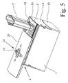
- 2 shows that the laboratory objects 2, for example the pipette tips, in a complete row, for example in a row of twelve Pipette tips that can be used in the laboratory at the same time, here in Fig. 2 shown by means of a twelve-channel multichannel pipette 5, the only is indicated schematically.
- FIG. 5 shows an eight-channel only Multi-channel pipette 5, used in the grid in the other direction can be.
- Fig. 2 shows first of all the basic principle that the opening and Closing movement of the lid 4 is an arcuate movement. Is to the lid 4 is attached to the receptacle 1 such that the Closed position starting with an arched opening movement - arrow 6 - the lid 4 in two opposite directions is possible.
- the Cover 4 can thus as shown in Fig. 2 in the orientation there to the right to move the rows of Expose laboratory objects 2 successively.
- the lid 4 can also starting from the middle closed position in the orientation of FIG. 2 swiveled to the left, starting from the right, the rows of laboratory objects 2 to be exposed successively.
- the shape of the receptacle 1 is arbitrary. receptacle 1 and cover 4 can thus be made square, for example.
- the 12 x 8 grid arrangement for example, requires a rectangular one Execution of the receptacle 1 with the lid 4. This is also the Standardausfiihrung. Do you have a rectangular shape of the receptacle 1 and cover 4, it is appropriate that the direction of the opening and closing movement 6 of the cover 4 parallel to the shorter sides the lid 4 is aligned.
- the illustrated embodiment shows in connection with Fig. 2 that the lid 4 in both directions until the release of about half of the Top, preferably slightly more than half of the top is openable.
- the individual rows of laboratory objects 2, in particular, are successive Pipette tips released. Only the row that is already “used up” or has been removed, in addition to the currently active row exposed, the others remain protected. The sterility of the remaining rows of laboratory objects 2 is secured. Tilting of the lid 4 is avoided because this is still so largely on the receptacle 1 remains that it does not tip sideways. This makes it possible to use one hand to implement the cover 4 in all cases.
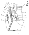
- the arcuate opening and closing movement 6 of the Cover 4 limited by delimitation points 7 at certain waypoints is.
- the boundary points 7 are according to the preferred embodiment and in the illustrated embodiment carried out like a catch and in Fig. 2 and Fig. 4 indicated. In particular, this ensures that an opening not possible for the cover 4 beyond the maximum open position is, but at least only by overcoming a clearly noticeable rest point.
- the opening movement of the lid indicated by the arrow 4 or the opening and closing movement then running in both directions 6 of the lid 4 there are various possibilities of the constructive Realization.
- the first thing is that the opening and closing movement the cover 4 an arcuate movement about a pivot axis which is significantly below the open top of the receptacle 1 and lies approximately on the center line of the receptacle 1.
- This basic principle is useful regardless of whether an arcuate opening movement is possible in two opposite directions, as in illustrated embodiment provided, or whether an opening and Closing movement of the cover 4 is only provided in one direction.
- the link guide 9 guides the cover 4 in its arcuate opening and closing movement 6 in space.
- the link guide 9 is arranged on the outer sides 10 of the receptacle 1.
- the arcuate opening and closing movement of the lid 4 can this design by means of a guide 9 even to a limited extent be non-circular.
- the guide 9 a circular arc-shaped opening and pivoting movement 6 of the cover 4 by one virtual swivel axis realized.
- the virtual pivot axis significantly below the bottom 8 of the receptacle 1 to find. In turn, it lies approximately on the center line of the receptacle 1.
- the link guide 9 on the respective outside 10 of the receptacle 1 have a single backdrop, according to both Directions of the opening movement 6 of the lid is open.
- the closed position of the cover 4 is then two sliding blocks 11 on the cover 4 in the setting 9 on the outside 10 of the receptacle 1. If the cover 4 is pivoted to one side, it leaves at accordingly Further pivoting a backdrop 11 the backdrop of the backdrop 9, the lid 4 does not tilt because it is due to the support on the Receiving container 1 on the one hand and the other sliding block 11 in the sliding guide 9 on the other hand is held.
- This swivel movement is after then the preferred example explained above at slightly more than that Half of the opening width of the receptacle 1 limited.
- the design of the scenery guide 9 is basically independent of this to realize how the opening and closing movement of the lid 4 in the rest runs. In principle, it can also be used for straight, non-arcuate movement of the cover 4 can be realized.
- the link guide 9 on the outer sides 10 of the Receiving container 1 each two sets 12, 13 arranged one above the other has, in each of which a sliding block 11 on a boom or on a The outer cheek 14 of the cover 4 runs.
- the two scenes 12, 13 at a distance of a few millimeters one above the other.
- the distance between the sliding blocks 11 in the backdrop or in the two scenes 12, 13 of the scenery guide 9 is more than half Width of the outside 10 of the receptacle 1.
- the upper backdrop 12 in Fig. 4 is open at the right end and closed at the left end somewhat beyond the center of the receptacle 1, so that there is the stop for the opening movement directed to the left the lid is formed.
- the lower backdrop 13 is on in FIG. 4 right end slightly closed beyond the center of the receptacle 1, so that for the rightward pivoting movement of the Cover 4 gives a stop.
- the sliding blocks 11 are not only designed as round pins, but elongated. The sliding block 11 can have a certain tilting moment the cover 4 and record in the corresponding setting 12; 13 derived. This results in an independent supporting function of the sliding block 11 in the backdrop 12; 13 with the lid partially open 4.
- the backdrop of the backdrop guide 9 with two backdrops 12, 13 preferably the upper backdrop 12, inside, preferably transverse to the backdrop guide, has an outlet channel 15 for the sliding block 11.
- the exit channel 15 is in the illustrated embodiment with a force applied lock 16, here a kind of spring tongue in the plastic material of the receptacle 1, equipped.
- This lock 16 acts in the backdrop 12 as a stop for the sliding block 11. When additional force is applied but the sliding block 11 can pass the lock 16 upwards the outlet channel 15 are moved out. Since in this situation the Fig.
- the lid 4 can be removed without tools from the receptacle 1 loosen or in the opposite direction, without tools, onto the receptacle 1 to a certain extent snap on. This is also for cleaning purposes very functional construction.
- the illustrated embodiment shows that the lid 4 is the receptacle 1 covered with the lateral outer cheeks 14 on the outer sides 10.
- the illustrated embodiment also shows the assignment of the sliding blocks 11 to the cover 4 and the backdrops 12, 13 to the outer sides 10 of the receptacle 1.
- This arrangement could also be reversed be provided by simply connecting the scenes 12, 13 to the outer cheeks 14 of the lid 4 on the sliding blocks 11 on the outer sides 10 of the receptacle 1 run.
- the illustrated and preferred embodiment also shows in FIG. 2, that on the outside 10 of the receptacle 1 an arcuate step 17 is provided, to which an arcuate edge 18 on the outer cheek 14 of the cover 4 corresponds. In the illustrated embodiment is between the step 17 and the edge 18 provided a gap, so a touch not given.
- This arrangement gives the possibility, if necessary additional support of the cover 4 with further lateral opening as in Fig. 2 to provide. This relieves the other bearing points, in particular the sliding block 11 in the sliding guide 9.
- the illustrated embodiments show that the cover 4 according to Art a cross slide with cover frame 19 and slidably guided thereon Cover plate 20 is constructed.
- the lid frame 19 is opposite the receptacle 1 movable in a first direction for opening and closing, while the cover plate 20 for opening and closing opposite the Lid frame 19 is movable in a second direction, which is substantially perpendicular to the first direction.
- Essentially means rectangular here that in principle, from the construction principle, also a minor one Deviation from an exactly rectangular course is possible. As a general rule there will of course be an exactly right-angled course.
- the illustrated embodiment shows that here the movement of the Cover frame 19 in the first direction the arc-shaped extensively explained above Is movement.
- the movement of the cover plate 20 with respect to the cover frame 19 in the second direction a sliding movement.
- This shifting movement is, as shown in FIG. 5, to the left and also possible to the right, so that in a similar manner as previously explained the opening of the cover 4 by moving the cover plate 20 opposite the lid frame 19 to about half of the top of the receptacle 1 in the second direction.
- the rest is provided, see Fig. 6, that the cover plate 20, the cover frame 19 to form the sliding guides 21 includes outside. This is the relevant for any abrasion Areas of the sliding guides 21 outside the opening area on the cover frame 19, so that there is contamination in the receptacle 1 Laboratory items 2 can not be carried out to this extent.
- the illustrated and preferred embodiment also shows that the Cover plate 20 is curved upwards in the second direction and below The pressure from the top is expanded to a certain extent. This allows the preloaded on the sliding guides 21 seated cover plate 20 in Closing state cannot be shifted accidentally and unintentionally. By Pressure on the cover plate 20 but spread the displacement guides 21 and moving the cover plate 20 on the cover frame 19 is facilitated.
- a cross slide is a separate invention that is independent from the initially explained invention of the arched opening movement is.
- a cross slide can, for example, also consist of two sliding guides, which essentially cross each other at right angles his.
- the three-stage design is essential for the cross slide from the upper edge of the receptacle 1 / lid frame 19 and lid frame 19 / cover plate 20.
- the receptacle 1 and / or the lid 4 are manufactured from plastic.
- a material is recommended for the application cases shown. that is autoclavable, for example stainless steel.
- the sliding guides 21 of the cover 4 gaps through which an air exchange the inside of the receptacle 1 with the ambient atmosphere can take place, which is particularly important when autoclaving.
- delimitation points also for the displacement of the cover plate 20 relative to the Lid frame 19 can be provided at appropriate positions.
- feet 26 are separate or integrally formed, in particular made from a the slipping counteracting elastomer (Fig. 1, 4).
Landscapes
- Health & Medical Sciences (AREA)
- Clinical Laboratory Science (AREA)
- Chemical & Material Sciences (AREA)
- Chemical Kinetics & Catalysis (AREA)
- Sampling And Sample Adjustment (AREA)
- Closures For Containers (AREA)
- Devices For Use In Laboratory Experiments (AREA)
Abstract
Description
- Fig. 1
- eine perspektivische Ansicht des gesamten Aufnahmebehälters schräg von unten,
- Fig. 2
- den Aufnahmebehälter aus Fig. 1 in einer Seitenansicht von einer kürzeren Außenseite her mit teilweise geöffnetem Deckel,
- Fig. 3
- den Aufnahmebehälter aus Fig. 1 im Längsschnitt parallel zu einer längeren Außenseite,
- Fig. 4
- den Aufnahmebehälter aus Fig. 1 von einer kürzeren Außenseite aus gesehen, in einem Schnitt in der Ebene unmittelbar hinter der Außenwange des Deckels,
- Fig. 5
- in einer perspektivischen Ansicht den Aufnahmebehälter in Längsrichtung teilweise geöffnet und
- Fig. 6
- den Aufnahmebehälter aus Fig. 1 im Schnitt parallel zu einer kürzeren Außenseite.
Claims (12)
- Aufnahmebehälter für vorzugsweise rasterförmig angeordnete Laborgegenstände (2), insbesondere Pipettenspitzen,
mit einem die offene Oberseite, von der aus die Laborgegenstände (2) von oben aus zugänglich sind, abschließenden Deckel (4),
dadurch gekennzeichnet, daß der Deckel (4) nach Art eines Kreuzschlittens mit Deckelrahmen (19) und daran verschiebbar geführter Deckelplatte (20) aufgebaut ist,
daß der Deckelrahmen (19) gegenüber dem Aufnahmebehälter (1) zum Öffnen und Schließen in einer ersten Richtung bewegbar ist und
daß die Deckelplatte (20) zum Öffnen und Schließen gegenüber dem Deckelrahmen (19) in einer zweiten Richtung bewegbar ist, die im wesentlichen rechtwinklig zur ersten Richtung verläuft. - Aufnahmebehälter nach Anspruch 1, dadurch gekennzeichnet, daß die Deckelplatte (20) den Deckelrahmen (19) zur Bildung von Verschiebefiihrungen (21) außen umfaßt und/oder
daß die Deckelplatte (20) in der zweiten Richtung nach oben gewölbt ist und sich unter Druck von oben um eine geringes Maß aufweitet. - Aufnahmebehälter für vorzugsweise rasterförmig angeordnete Laborgegenstände (2), insbesondere Pipettenspitzen,
mit einem die offene Oberseite, von der aus die Laborgegenstände (2) von oben aus zugänglich sind, abschließenden Deckel (4),
insbesondere nach Anspruch 1 oder 2,
dadurch gekennzeichnet, daß die Öffnungs- und Schließbewegung des Deckels (4) eine bogenförmige Bewegung um eine Schwenkachse ist, die erheblich unterhalb der offenen Oberseite und etwa auf der Mittellinie des Aufnahmebehälters (1) liegt. - Aufnahmebehälter nach Anspruch 3, dadurch gekennzeichnet, daß der Deckel (4) derart an dem Aufnahmebehälter (1) befestigt ist, daß von der Schließstellung ausgehend eine bogenförmige Öffnungsbewegung (6) des Deckels (4) in zwei einander entgegengesetzte Richtungen möglich ist,
wobei, vorzugsweise, die Richtung der Öffnungs- und Schließbewegung (6) des Deckels (4) parallel zu den kürzeren Seiten des Deckels (4) ausgerichtet ist und/oder der Deckel (4) in beiden Richtungen jeweils bis zur Freigabe von etwa der Hälfte der Oberseite, vorzugsweise etwas mehr als der Hälfte der Oberseite, öffenbar ist. - Aufnahmebehälter nach Anspruch 3 oder 4, dadurch gekennzeichnet, daß die bogenförmige Öffnungs- und Schließbewegung (6) des Deckels (4) mittels vorzugsweise rastenartigen Begrenzungspunkten (7) an bestimmten Punkten begrenzt ist.
- Aufnahmebehälter nach einem der Ansprüche 3 bis 5, dadurch gekennzeichnet, daß die bogenförmige Öffnungs- und Schließbewegung (6) des Deckels (4) eine Schwenkbewegung um eine körperlich vorhandene, an oder über dem Boden (8) angeordnete Schwenkachse ist oder
daß die bogenförmige Öffnungs- und Schließbewegung (6) des Deckels (4) eine durch eine Kulissenführung (9), vorzugsweise an den Außenseiten (10) des Aufnahmebehälters (1), realisierte Bewegung ist,
wobei, vorzugsweise, die Kulissenführung (9) eine kreisbogenförmige Öffnungs- und Schließbewegung (6) des Deckels (4) um eine virtuelle Schwenkachse realisiert und,
weiters vorzugsweise, die virtuelle Schwenkachse unterhalb des Bodens (8) des Aufnahmebehälters (1) liegt. - Aufnahmebehälter für vorzugsweise rasterförmig angeordnete Laborgegenstände (2), insbesondere Pipettenspitzen,
mit einem die offene Oberseite, von der aus die Laborgegenstände (2) von oben aus zugänglich sind, abschließenden Deckel (4),
insbesondere nach einem der Ansprüche 1 bis 6,
dadurch gekennzeichnet, daß die Öffnungs- und Schließbewegung des Deckels (4) eine durch eine Kulissenführung (9), vorzugsweise an den Außenseiten (10) des Aufnahmebehälters (1), realisierte Bewegung ist und daß jeweils zwei übereinander angeordnete Kulissen (12; 13) vorgesehen sind, in denen jeweils ein Kulissenstein (11) an einem Ausleger oder an einer Außenwange (14) des Deckels (4) läuft. - Aufnahmebehälter nach Anspruch 7, dadurch gekennzeichnet, daß die Kulissen (12; 13) an den Außenseiten (10) des Aufnahmebehälters (1) angeordnet sind und/oder
daß die beiden Kulissen (12; 13) übereinander einen Abstand von wenigen Millimetern haben und/oder
daß die beiden Kulissen (12; 13) jeweils an einem Ende voneinander weg gerichtet offen und am jeweils gegenüberliegenden Ende geschlossen sind und, vorzugsweise, die geschlossenen Enden jeweils etwas jenseits der Mitte des Aufnahmebehälters (1) liegen. - Aufnahmebehälter nach Anspruch 6 oder 7 oder 8, dadurch gekennzeichnet, daß der Abstand der Kulissensteine (11) in der Kulisse bzw. in den Kulissen (12; 13) mehr als bzw. etwa die halbe Breite der Außenseiten (10) beträgt und/oder
daß die Kulisse, insbesondere die obere Kulisse (12), einen Austrittskanal (15) für den Kulissenstein (11) aufweist,
wobei, vorzugsweise, der Austrittskanal (15) eine durch Kraftbeaufschlagung überwindbare Sperre (16) aufweist. - Aufnahmebehälter nach Anspruch 6 oder nach einem der Ansprüche 7 bis 9, dadurch gekennzeichnet, daß an der Außenseite (10) des Aufnahmebehälters (1) eine bogenförmige Stufe (17) vorgesehen ist, zu der ein bogenförmiger Rand (18) an der Außenwange (14) des Deckels (4) korrespondiert und/oder
daß die Zuordnung von Kulissen (12; 13) und Kulissensteinen (11) zu Außenseiten (10) und Deckel (4) genau umgekehrt wie zuvor geschildert vorgesehen ist. - Aufnahmebehälter nach einem der voranstehenden Ansprüche, dadurch gekennzeichnet, daß der Aufnahmebehälter (1) für eine Anordnung der Laborgegenstände (2) in einer Rasteranordnung 12 x 8 ausgeführt ist und/oder
daß der Aufnahmebehälter (1) und der Deckel (4) rechteckig ausgeführt sind. - Aufnahmebehälter nach einem der voranstehenden Ansprüche, dadurch gekennzeichnet, daß der Deckel (4) auf der Oberseite etwa mittig eine optisch hervorgehobene Betätigungsfläche (22) aufweist und daß die Betätigungsfläche (22) vorzugsweise mit einer Gleitschutzausformung (23) und/oder mit Markierungen (24) versehen ist und/oder
daß der Aufnahmebehälter (1) und/oder der Deckel (4) aus Kunststoff, insbesondere aus autoklavierbarem Kunststoff, bestehen und/oder
daß der Aufnahmebehälter (1) doppelwandig ausgeführt ist und/oder
daß die Führungen des Deckels (4) Spalte aufweisen, durch die ein Luftaustausch des Inneren des Aufnahmebehälters (1) mit der Umgebungsatmosphäre stattfinden kann.
Applications Claiming Priority (2)
| Application Number | Priority Date | Filing Date | Title |
|---|---|---|---|
| DE20305608U | 2003-04-04 | ||
| DE20305608U DE20305608U1 (de) | 2003-04-04 | 2003-04-04 | Aufnahmebehälter für vorzugsweise rasterförmig angeordnete Laborgegenstände, insbesondere Pipettenspitzen |
Publications (2)
| Publication Number | Publication Date |
|---|---|
| EP1464402A2 true EP1464402A2 (de) | 2004-10-06 |
| EP1464402A3 EP1464402A3 (de) | 2006-01-11 |
Family
ID=32842387
Family Applications (1)
| Application Number | Title | Priority Date | Filing Date |
|---|---|---|---|
| EP04005935A Withdrawn EP1464402A3 (de) | 2003-04-04 | 2004-03-12 | Aufnahmebehälter für rasterförmig angeordnete Laborgegenstände, insbesondere Pipettenspitzen |
Country Status (2)
| Country | Link |
|---|---|
| EP (1) | EP1464402A3 (de) |
| DE (1) | DE20305608U1 (de) |
Cited By (2)
| Publication number | Priority date | Publication date | Assignee | Title |
|---|---|---|---|---|
| WO2007045888A3 (en) * | 2005-10-20 | 2007-11-15 | Alba Scient Services Ltd | Apparatus for laboratory ware |
| CN114433272A (zh) * | 2019-11-22 | 2022-05-06 | 牛永菡 | 一种模拟人手操作的检验试管晃动装置 |
Families Citing this family (1)
| Publication number | Priority date | Publication date | Assignee | Title |
|---|---|---|---|---|
| CN109230449B (zh) * | 2018-08-22 | 2024-03-12 | 威海威高生物科技有限公司 | 转向样本架 |
Family Cites Families (12)
| Publication number | Priority date | Publication date | Assignee | Title |
|---|---|---|---|---|
| US4676377A (en) * | 1984-09-14 | 1987-06-30 | Rainin Instrument Co., Inc. | Enclosed pipette tip rack |
| DE8805448U1 (de) * | 1988-04-25 | 1988-06-16 | Schiedel, Gert, 6913 Mühlhausen | Ständer für Pipettenspitzen |
| US5082631A (en) * | 1990-06-07 | 1992-01-21 | Transpan Company | Transport tray with pivotal circular cam ramp for biological samples |
| DE4208503C1 (en) * | 1992-03-17 | 1993-07-15 | Greiner Gmbh, 7440 Nuertingen, De | Pipette point sterilising container - has sliding locking lids and perforated plates to hold pipette points alternately up and down |
| DE4240280C2 (de) * | 1992-12-01 | 1995-02-23 | Bernd Dr Steinbrenner | Vorrichtung zum Bereitstellen vorzugsweise sterilisierter Pipettenspitzen |
| DE19525258C2 (de) * | 1995-07-11 | 1997-10-09 | Bernd Dr Steinbrenner | Box für rasterförmig angeordnete Laborgegenstände |
| DE29518413U1 (de) * | 1995-11-21 | 1996-03-14 | Hoffner GmbH Kunststofftechnik, 68753 Waghäusel | Box für die Aufnahme von Pipettenspitzen |
| US5673811A (en) * | 1996-03-04 | 1997-10-07 | Contico International, Inc. | Food bin assembly |
| DE29607444U1 (de) * | 1996-04-24 | 1997-08-21 | Steinbrenner, Bernd, Dr., 69257 Wiesenbach | Vorrichtung zur hochreinen Verpackung und Anwendung von Laboreinmalartikeln |
| DE19824117A1 (de) * | 1997-05-30 | 1998-12-03 | Bernd Dr Steinbrenner | Schiebedeckel sowie Box |
| FR2784076B1 (fr) * | 1998-10-06 | 2000-12-22 | Gilson Sa | Ensemble comprenant des recharges de cones de pipette empilees |
| US6672471B2 (en) * | 2001-04-02 | 2004-01-06 | Harley Cross | Tablet box construction |
-
2003
- 2003-04-04 DE DE20305608U patent/DE20305608U1/de not_active Expired - Lifetime
-
2004
- 2004-03-12 EP EP04005935A patent/EP1464402A3/de not_active Withdrawn
Cited By (3)
| Publication number | Priority date | Publication date | Assignee | Title |
|---|---|---|---|---|
| WO2007045888A3 (en) * | 2005-10-20 | 2007-11-15 | Alba Scient Services Ltd | Apparatus for laboratory ware |
| CN114433272A (zh) * | 2019-11-22 | 2022-05-06 | 牛永菡 | 一种模拟人手操作的检验试管晃动装置 |
| CN114433272B (zh) * | 2019-11-22 | 2023-11-28 | 修雪梅 | 一种模拟人手操作的检验试管晃动装置 |
Also Published As
| Publication number | Publication date |
|---|---|
| DE20305608U1 (de) | 2004-08-12 |
| EP1464402A3 (de) | 2006-01-11 |
Similar Documents
| Publication | Publication Date | Title |
|---|---|---|
| EP0961558B1 (de) | Koffer mit auswechselbaren schalen | |
| DE69316423T2 (de) | Ablagemechanismus für den Eingabestift an einem Gerät mit einer Eingabefläche | |
| DE19645892A1 (de) | Deckelgefäß | |
| DE102016112853A1 (de) | Stapelbarer Systembehälter | |
| EP2189381A1 (de) | Tragbarer Transport- oder Lagerbehälter | |
| EP2392286B1 (de) | Lagereinheit für Knochenschrauben, Set und chirurgischer Behälter | |
| EP3285930B1 (de) | Träger zum aufnehmen und lagern von laborgefässen | |
| DE202016103774U1 (de) | Stapelbarer Systembehälter | |
| DE2113434B2 (de) | Behaelter zur aufnahme und einzelnen ausgabe von schreibstiftminen | |
| EP3814064A1 (de) | Aufbewahrungseinrichtung | |
| DE202017007346U1 (de) | Anzucht- und Probennahme-Vorrichtung für Pflanzen | |
| DE202015106824U1 (de) | Transportbox | |
| DE60104999T2 (de) | Pipette mit einstellbarem auswurfhebel zur aufnahme von flüssigen proben | |
| EP1464402A2 (de) | Aufnahmebehälter für rasterförmig angeordnete Laborgegenstände, insbesondere Pipettenspitzen | |
| DE10361167A1 (de) | Verpackungsbox für Laborgegenstände | |
| DE2421969A1 (de) | Offener ablegebehaelter | |
| DE19824117A1 (de) | Schiebedeckel sowie Box | |
| EP4382804A1 (de) | Feuerzeughülle | |
| DE4300231C1 (de) | Petrischale | |
| DE102015121865A1 (de) | Transportbox | |
| AT525004A2 (de) | Vorrichtung zur Aufbewahrung und Präsentation von Waren | |
| DE102012101155A1 (de) | Mophalter, Moptuch und Moptuchvorratsbehälter | |
| DE102019109207B3 (de) | Vorrichtung zur Aufnahme von Proben in einem Mikroskop | |
| DE202008018043U1 (de) | Gärgutträger mit Belüftungssystem | |
| DE3640395C1 (en) | Feed apparatus for pigs |
Legal Events
| Date | Code | Title | Description |
|---|---|---|---|
| PUAI | Public reference made under article 153(3) epc to a published international application that has entered the european phase |
Free format text: ORIGINAL CODE: 0009012 |
|
| AK | Designated contracting states |
Kind code of ref document: A2 Designated state(s): AT BE BG CH CY CZ DE DK EE ES FI FR GB GR HU IE IT LI LU MC NL PL PT RO SE SI SK TR |
|
| AX | Request for extension of the european patent |
Extension state: AL LT LV MK |
|
| PUAL | Search report despatched |
Free format text: ORIGINAL CODE: 0009013 |
|
| AK | Designated contracting states |
Kind code of ref document: A3 Designated state(s): AT BE BG CH CY CZ DE DK EE ES FI FR GB GR HU IE IT LI LU MC NL PL PT RO SE SI SK TR |
|
| AX | Request for extension of the european patent |
Extension state: AL LT LV MK |
|
| 17P | Request for examination filed |
Effective date: 20060622 |
|
| AKX | Designation fees paid |
Designated state(s): AT BE BG CH CY CZ DE DK EE ES FI FR GB GR HU IE IT LI LU MC NL PL PT RO SE SI SK TR |
|
| 17Q | First examination report despatched |
Effective date: 20070712 |
|
| STAA | Information on the status of an ep patent application or granted ep patent |
Free format text: STATUS: THE APPLICATION IS DEEMED TO BE WITHDRAWN |
|
| 18D | Application deemed to be withdrawn |
Effective date: 20151001 |