EP1464147B1 - Controle de synchronisation dans des recepteurs et des emetteurs de donnees - Google Patents
Controle de synchronisation dans des recepteurs et des emetteurs de donnees Download PDFInfo
- Publication number
- EP1464147B1 EP1464147B1 EP02781727A EP02781727A EP1464147B1 EP 1464147 B1 EP1464147 B1 EP 1464147B1 EP 02781727 A EP02781727 A EP 02781727A EP 02781727 A EP02781727 A EP 02781727A EP 1464147 B1 EP1464147 B1 EP 1464147B1
- Authority
- EP
- European Patent Office
- Prior art keywords
- receiver
- analog
- digital
- phase
- clock
- Prior art date
- Legal status (The legal status is an assumption and is not a legal conclusion. Google has not performed a legal analysis and makes no representation as to the accuracy of the status listed.)
- Expired - Lifetime
Links
- 238000005070 sampling Methods 0.000 claims abstract description 30
- 238000004891 communication Methods 0.000 claims description 13
- 238000011084 recovery Methods 0.000 claims description 10
- 238000001914 filtration Methods 0.000 claims description 2
- 229920005994 diacetyl cellulose Polymers 0.000 abstract description 5
- 208000037957 feline spongiform encephalopathy Diseases 0.000 abstract 1
- 239000013078 crystal Substances 0.000 description 8
- 239000000523 sample Substances 0.000 description 7
- 230000001360 synchronised effect Effects 0.000 description 4
- 238000013461 design Methods 0.000 description 3
- 238000010586 diagram Methods 0.000 description 3
- 238000013459 approach Methods 0.000 description 2
- 238000000034 method Methods 0.000 description 2
- 239000000758 substrate Substances 0.000 description 2
- 238000012935 Averaging Methods 0.000 description 1
- RYGMFSIKBFXOCR-UHFFFAOYSA-N Copper Chemical compound [Cu] RYGMFSIKBFXOCR-UHFFFAOYSA-N 0.000 description 1
- 238000010276 construction Methods 0.000 description 1
- 229910052802 copper Inorganic materials 0.000 description 1
- 239000010949 copper Substances 0.000 description 1
- 238000004519 manufacturing process Methods 0.000 description 1
- 229920000729 poly(L-lysine) polymer Polymers 0.000 description 1
- 238000005215 recombination Methods 0.000 description 1
- 230000006798 recombination Effects 0.000 description 1
- 239000013074 reference sample Substances 0.000 description 1
- 239000007787 solid Substances 0.000 description 1
Images


Classifications
-
- H—ELECTRICITY
- H04—ELECTRIC COMMUNICATION TECHNIQUE
- H04L—TRANSMISSION OF DIGITAL INFORMATION, e.g. TELEGRAPHIC COMMUNICATION
- H04L7/00—Arrangements for synchronising receiver with transmitter
- H04L7/02—Speed or phase control by the received code signals, the signals containing no special synchronisation information
-
- H—ELECTRICITY
- H04—ELECTRIC COMMUNICATION TECHNIQUE
- H04L—TRANSMISSION OF DIGITAL INFORMATION, e.g. TELEGRAPHIC COMMUNICATION
- H04L7/00—Arrangements for synchronising receiver with transmitter
- H04L7/0016—Arrangements for synchronising receiver with transmitter correction of synchronization errors
- H04L7/002—Arrangements for synchronising receiver with transmitter correction of synchronization errors correction by interpolation
- H04L7/0029—Arrangements for synchronising receiver with transmitter correction of synchronization errors correction by interpolation interpolation of received data signal
-
- H—ELECTRICITY
- H04—ELECTRIC COMMUNICATION TECHNIQUE
- H04B—TRANSMISSION
- H04B1/00—Details of transmission systems, not covered by a single one of groups H04B3/00 - H04B13/00; Details of transmission systems not characterised by the medium used for transmission
- H04B1/38—Transceivers, i.e. devices in which transmitter and receiver form a structural unit and in which at least one part is used for functions of transmitting and receiving
- H04B1/40—Circuits
-
- H—ELECTRICITY
- H04—ELECTRIC COMMUNICATION TECHNIQUE
- H04L—TRANSMISSION OF DIGITAL INFORMATION, e.g. TELEGRAPHIC COMMUNICATION
- H04L25/00—Baseband systems
- H04L25/02—Details ; arrangements for supplying electrical power along data transmission lines
-
- H—ELECTRICITY
- H04—ELECTRIC COMMUNICATION TECHNIQUE
- H04L—TRANSMISSION OF DIGITAL INFORMATION, e.g. TELEGRAPHIC COMMUNICATION
- H04L25/00—Baseband systems
- H04L25/02—Details ; arrangements for supplying electrical power along data transmission lines
- H04L25/14—Channel dividing arrangements, i.e. in which a single bit stream is divided between several baseband channels and reassembled at the receiver
-
- H—ELECTRICITY
- H04—ELECTRIC COMMUNICATION TECHNIQUE
- H04L—TRANSMISSION OF DIGITAL INFORMATION, e.g. TELEGRAPHIC COMMUNICATION
- H04L25/00—Baseband systems
- H04L25/02—Details ; arrangements for supplying electrical power along data transmission lines
- H04L25/03—Shaping networks in transmitter or receiver, e.g. adaptive shaping networks
- H04L25/03006—Arrangements for removing intersymbol interference
- H04L2025/03433—Arrangements for removing intersymbol interference characterised by equaliser structure
- H04L2025/03439—Fixed structures
- H04L2025/03445—Time domain
- H04L2025/03471—Tapped delay lines
- H04L2025/03484—Tapped delay lines time-recursive
Definitions
- the invention relates to timing control for data receivers and transmitters in transceivers for multi-channel communication systems.
- One such system is the 1000BASE-T "Gigabit" system.
- the 1000BASE-T system operates over 4 pairs of copper cable and transmits 4D symbols where each dimension can be assigned a value from the alphabet ⁇ -2,-1,0,+1,+2 ⁇ .
- the receiver is required to receive each 1D symbol with a very small probability of error and is also required to align the four 1D symbols to reconstruct the 4D symbol.
- the spatial diversity of the channel implies that four Analog to Digital Converters (ADCs) are required to receive the 4D symbol, one per cable pair.
- ADCs Analog to Digital Converters
- the 4D Symbol is split into four 1D symbols at the transmitter and then recombined at some point in the receiver. This recombination is vital in order to achieve performance targets imposed by the IEEE standard.
- SRS symbol rate sampling
- ADCs analog to digital converters
- a communications system It is usual in a communications system to derive the clock for the system from an external crystal (XTAL) and a phase lock loop (PLL). If the sample rate is high (greater than 30MHz) or if the frequency or phase must be varied a PLL is used. As an example a PLL can be used to multiply a 25MHz XTAL derived clock by five to generate a 125MHz clock. This circuit can be designed so the frequency and phase of the 125MHz clock can be digitally controlled.
- XTAL external crystal
- PLL phase lock loop
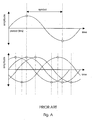
- Fig. A illustrates the sampling required in a four dimensional system with SRS.
- the analog waveform generated by transmitting a +2 followed by a -2 is given along with the optimum sampling points. Only by sampling at these points will the performance of the receiver be maximised.
- the lower graph includes the waveforms on the other three dimensions, and the variations in sampling points can be seen. This illustrates the point that all four dimensions must sample at different phases and therefore different clocks are required.
- the frequency of the incoming symbols are known and are the same as the frequency at which the master itself it transmitting.
- the ADCs on the receive path must still be clocked so that they sample at their respective optimum sampling phases. This implies that a total of five clocks are required, one of which is locked to the local crystal oscillator.
- United States Patent Specification No. 5970093 (Tiernan ) describes a digital receiver for signals such as television signals. Two analog (I & Q) signals are sampled and transferred to two separate A/D converters.
- European Patent Specification No. EP1128622 (Virata ) describes a receiver method in which an input symbol is sampled at a local sampling rate derived from a local clock and a reference sample rate is derived and compared with the local sampling rate.
- US Patent No. 5,703,905 describes a timing recovery system which requires that the phases of the signals received be sensed and selected in order to select a preferred timing signal for the system as a whole.
- US Patent No. 6,141,378 similarly requires that signal phase be determined.
- WO 00/65772 discloses an arrangement in which ADCs of different channels have different clocks. There is provided circuitry to determine the phase of the signal received from the plurality of channels by the ADCs.
- US Patent No. 6,307,906 also provides an arrangement in which there is circuitry to determine the phase of a signal received from a plurality of channels by an ADC. The phase difference between channels is calculated, averaging the all data stream phases, and an average data centre for all the data input channels determined.
- the invention is directed towards providing a communication circuit for multi-dimensional symbol streams which overcomes at least some of the problems (a) to (c) set out above.
- the receiver comprises means for down-sampling.
- the receiver comprises a fractionally spaced equaliser associated with each channel, each fractionally spaced equaliser comprising said digital filter and said down-sampling means.
- each fractionally spaced equaliser comprises a filter in which data values are separated by less than a symbol period in time, and means for combining the data values in a linear manner using coefficients to perform channel equalisation prior to down-sampling to the symbol rate.
- the circuit comprises a single phased-locked loop circuit comprising means for locking to a frequency and driving all of the receiver ADCs and the transmitter DACs.
- the receiver comprises means for driving the ADCs at close to or during a digital logic switching quiet period.
- the invention provides a transceiver comprising a communication circuit as defined above.
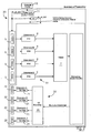
- a slave mode Gigabit transceiver 1 comprises a receiver 2 and a transmitter 3.
- the receiver 2 comprises an ADC 5 for each of four Gigabit channels A, B, C, and D.
- Each ADC 5 feeds into a fractionally spaced equaliser 6, in turn feeding a Viterbi trellis decoder 7.
- a timing recovery circuit 10 is connected to an FSE input and output.
- a phase loop and mixer circuit 11 receives a clock signal from an external crystal 12, and uses the timing recovery output to deliver a 250 MHz clock to the ADCs and a 125 MHz clock to the remainder of the circuitry.
- the transmitter 3 comprises a 4D encoder 20 feeding a transmit filter 21 for each dimension, in turn feeding a DAC 22 for each dimension.
- a master mode transceiver 30 comprises a receiver 31 and a transmitter 32. Parts similar to those of Fig. 1 are assigned the same reference numerals. In this case the phase loop and mixer circuit 11 is not linked to a timing recovery circuit.
- the Gigabit Ethernet standard specifies that any Gigabit Ethernet link must consist of two transceivers, one of which operates in master mode and the other in slave mode. The assignment of these two modes is done prior to the establishment of a link.
- master mode a transceiver uses a clock generated from a local source, usually a crystal, to drive the DACs associated with its transmitter.
- a slave must then recover the symbols transmitted by the master and ensure the symbols it sends back to the master are transmitted at this recovered rate. In this way the master can assume the symbols arriving at its receiver are at the same frequency with which it is transmitting. In essence the slave has locked itself to the master with respect to symbol frequency.
- the slave transceiver 1 recovers the master's clock from the incoming symbols using the circuit 10 and then uses this recovered clock to transmit symbols back to the master.
- the 250MHz clock is derived from the timing recovery circuit 10 and hence is locked to the incoming symbols (which have been sent by the master).
- the remaining receive circuitry and the transmit circuitry are driven off a similarly derived 125MHz clock. This ensures the symbols transmitted back to the master are done so at the correct frequency. Thus, higher power consumption does not arise because of the higher oversampling rate.
- the FSEs 6 ensure the optimum sampling phase is selected digitally.
- the receivers 2 and 31 do not need multiple asynchronous clocks, as instead all channels sample at the same rate and phase, namely oversampling at a factor of 2. Thus, there is only one clock domain, and asynchronous clock cross interference is avoided. Also, the circuitry is much simpler than heretofore because it does not need to determine the phase of the incoming signals.
- the 250MHz clock is derived from the local external crystal oscillator 12.
- a 125MHz clock is derived from this source also and is used to drive the remainder of the receiver and the transmitter.
- the fractionally spaced equalisers 6 ensure the optimum sampling phase is selected digitally. No timing recovery circuitry is required in this mode.
- FSE fractionally spaced equalisers
- the samples from the synchronously driven ADCs are presented to four FSEs which both interpolate and equalise these symbols before down-sampling them to the symbol rate.
- the output of the FSE is an estimate of the 1D symbols that were transmitted at the far end of the link. These are then combined into estimates of the 4D symbol that is then passed to the Viterbi for decoding.
- Each FSE 6 comprises a filter whose data values are separated by less than a symbol period in time. These data values are then combined in a linear fashion using coefficients to perform channel equalisation prior to down-sampling to the symbol rate.
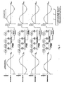
- Digital circuitry consists of combinatorial logic (AND, OR gates etc.) interspersed between registers. These registers are updated every positive edge of the clock and this may place a new signal at the input to the combinatorial logic.
- logic values change (either at a register output or a gate output) some current is drawn from the supply. It is common for a large amount of current to be drawn immediately after the positive edge of the clock and for the amount of current drawn to fall rapidly after this point.
- Analog circuitry relies on accurate biasing and power supplies in order to maintain a linear response and achieve satisfactorily small signal distortion. To achieve this it is desirable to drive the ADCs in a "quiet period" i.e. a period of time in which it is known the remainder of the circuit is not drawing too much current. Clearly it is therefore desirable to avoid driving the ADCs near the positive edge of a clock driving large amounts digital logic.
- Fig. 4 illustrates how synchronous (top) and non-synchronous (bottom) sampling schemes compare in terms of ADCs being driven during noisy periods.
- the invention is not limited to the embodiments described but may be varied in construction and detail.
- the invention may be applied to receivers or transmitters other than for master/slave operation where a clock is recovered.
- An example is the 100 BASE-T Ethernet standard.
Landscapes
- Engineering & Computer Science (AREA)
- Computer Networks & Wireless Communication (AREA)
- Signal Processing (AREA)
- Power Engineering (AREA)
- Synchronisation In Digital Transmission Systems (AREA)
- Dc Digital Transmission (AREA)
- Cable Transmission Systems, Equalization Of Radio And Reduction Of Echo (AREA)
Abstract
Claims (6)
- Circuit de communication comprenant un récepteur (2) et un émetteur (3), dans lequel le récepteur comprend une pluralité de convertisseurs analogiques/numériques (5), chacun des convertisseurs analogiques/numériques étant adapté pour recevoir un signal sur l'un d'une pluralité de canaux, respectivement, et l'émetteur comprend une pluralité de convertisseurs numériques/analogiques (22), chacun des convertisseurs numériques/analogiques étant adapté pour transmettre un signal sur l'un desdits canaux, respectivement, caractérisé en ce que :le récepteur comprend un circuit de récupération de synchronisation comprenant un moyen pour récupérer une horloge reçue à partir du signal entrant de l'un desdits canaux sans déterminer la phase du signal entrant ;le récepteur comprend un moyen (10, 11, 12) pour commander chacun des convertisseurs analogiques/numériques (5) avec la même horloge à la même cadence et à la même phase pour échantillonner le signal entrant sur chacun desdits canaux à une cadence qui est au moins supérieure par un facteur de deux à la cadence de symboles de chacun desdits canaux ;le récepteur comprend en outre dans chaque canal un égaliseur à espacement fractionnaire qui filtre le signal échantillonné pour récupérer une phase optimale ; etl'émetteur (3) comprend un moyen pour commander chacun des convertisseurs numériques/analogiques (22) à partir de la même horloge à la même cadence et à la même phase que l'horloge commandant les convertisseurs analogiques/numériques du récepteur.
- Circuit de communication selon la revendication 1, dans lequel le récepteur comprend un moyen de sous-échantillonnage.
- Circuit de communication selon l'une quelconque des revendications précédentes, dans lequel chaque égaliseur à espacement fractionnaire comprend un filtre dans lequel des valeurs de données sont séparées par moins d'une période de symbole dans le temps, et un moyen pour combiner les valeurs de données d'une manière linéaire en utilisant des coefficients pour effectuer une égalisation de canal avant le sous-échantillonnage à la cadence de symboles.
- Circuit de communication selon l'une quelconque des revendications précédentes, dans lequel le circuit comprend un circuit à boucle asservie en phase unique comprenant un moyen pour effectuer un verrouillage sur une fréquence et commander tous les convertisseurs analogiques/numériques du récepteur et convertisseurs numériques/analogiques de l'émetteur.
- Circuit de communication selon l'une quelconque des revendications précédentes, dans lequel le récepteur comprend un moyen pour commander les convertisseurs analogiques/numériques près d'une période calme de commutation logique numérique ou durant une telle période.
- Emetteur-récepteur comprenant un circuit de communication selon l'une quelconque des revendications précédentes.
Applications Claiming Priority (3)
| Application Number | Priority Date | Filing Date | Title |
|---|---|---|---|
| US34698302P | 2002-01-11 | 2002-01-11 | |
| US346983P | 2002-01-11 | ||
| PCT/IE2002/000168 WO2003058902A2 (fr) | 2002-01-11 | 2002-12-11 | Controle de synchronisation dans des recepteurs et d'emetteurs de donnees |
Publications (2)
| Publication Number | Publication Date |
|---|---|
| EP1464147A2 EP1464147A2 (fr) | 2004-10-06 |
| EP1464147B1 true EP1464147B1 (fr) | 2011-02-09 |
Family
ID=23361851
Family Applications (1)
| Application Number | Title | Priority Date | Filing Date |
|---|---|---|---|
| EP02781727A Expired - Lifetime EP1464147B1 (fr) | 2002-01-11 | 2002-12-11 | Controle de synchronisation dans des recepteurs et des emetteurs de donnees |
Country Status (8)
| Country | Link |
|---|---|
| US (1) | US7158562B2 (fr) |
| EP (1) | EP1464147B1 (fr) |
| JP (1) | JP4554934B2 (fr) |
| KR (1) | KR100806536B1 (fr) |
| AU (1) | AU2002348700A1 (fr) |
| CA (1) | CA2471255A1 (fr) |
| DE (1) | DE60239159D1 (fr) |
| WO (1) | WO2003058902A2 (fr) |
Families Citing this family (11)
| Publication number | Priority date | Publication date | Assignee | Title |
|---|---|---|---|---|
| US7379919B2 (en) * | 2000-04-11 | 2008-05-27 | Mastercard International Incorporated | Method and system for conducting secure payments over a computer network |
| US20100228668A1 (en) * | 2000-04-11 | 2010-09-09 | Hogan Edward J | Method and System for Conducting a Transaction Using a Proximity Device and an Identifier |
| US20100223186A1 (en) * | 2000-04-11 | 2010-09-02 | Hogan Edward J | Method and System for Conducting Secure Payments |
| US8133113B2 (en) * | 2004-10-04 | 2012-03-13 | Igt | Class II/Class III hybrid gaming machine, system and methods |
| US7421014B2 (en) * | 2003-09-11 | 2008-09-02 | Xilinx, Inc. | Channel bonding of a plurality of multi-gigabit transceivers |
| EP1763146A1 (fr) * | 2005-09-12 | 2007-03-14 | Sigma Designs, Inc. | Puce de bande a base à bande ultra large comprenant un radio utilisant un réseau intelligent et procédé correspondant |
| US7873132B2 (en) * | 2005-09-21 | 2011-01-18 | Hewlett-Packard Development Company, L.P. | Clock recovery |
| US8638843B2 (en) | 2010-06-03 | 2014-01-28 | Fujitsu Limited | Receiving device and receiving method |
| JP5700546B2 (ja) | 2010-06-03 | 2015-04-15 | 富士通株式会社 | 受信装置および受信方法 |
| JP5545098B2 (ja) * | 2010-07-29 | 2014-07-09 | 富士通株式会社 | Ad変換装置 |
| US8976050B1 (en) * | 2013-09-12 | 2015-03-10 | Fujitsu Semiconductor Limited | Circuitry and methods for use in mixed-signal circuitry |
Family Cites Families (17)
| Publication number | Priority date | Publication date | Assignee | Title |
|---|---|---|---|---|
| US6009130A (en) * | 1995-12-28 | 1999-12-28 | Motorola, Inc. | Multiple access digital transmitter and receiver |
| US5970093A (en) | 1996-01-23 | 1999-10-19 | Tiernan Communications, Inc. | Fractionally-spaced adaptively-equalized self-recovering digital receiver for amplitude-Phase modulated signals |
| US5703905A (en) | 1996-02-16 | 1997-12-30 | Globespan Technologies, Inc. | Multi-channel timing recovery system |
| US5838744A (en) * | 1996-10-22 | 1998-11-17 | Talx Corporation | High speed modem and method having jitter-free timing recovery |
| JPH10336087A (ja) * | 1997-05-30 | 1998-12-18 | Kyocera Corp | 最大比合成送信ダイバーシティ装置 |
| US6307906B1 (en) * | 1997-10-07 | 2001-10-23 | Applied Micro Circuits Corporation | Clock and data recovery scheme for multi-channel data communications receivers |
| JP3660589B2 (ja) * | 1998-03-09 | 2005-06-15 | ブロードコム コーポレイション | ギガビット・イーサネット送受信機 |
| GB9905997D0 (en) * | 1999-03-16 | 1999-05-12 | Koninkl Philips Electronics Nv | Radio receiver |
| JP4547064B2 (ja) * | 1999-03-24 | 2010-09-22 | 株式会社アドバンテスト | A/d変換装置およびキャリブレーション装置 |
| DE60031542T2 (de) * | 1999-04-22 | 2007-08-23 | Broadcom Corp., Irvine | Phy-steuerungsmodul für einen gigabit-transceiver mit mehreren paaren |
| CN1157943C (zh) * | 1999-07-16 | 2004-07-14 | 汤姆森许可公司 | 高清晰度电视接收机中帮助载波获取的可选增益调整 |
| JP3890867B2 (ja) * | 1999-09-17 | 2007-03-07 | 松下電器産業株式会社 | 受信機および送受信機 |
| GB2359705B (en) | 2000-02-28 | 2003-11-26 | Virata Ltd | xDSL sample rate compensation using phase balancing |
| JP3745962B2 (ja) * | 2001-01-24 | 2006-02-15 | 株式会社アドバンテスト | インターリーブad変換方式波形ディジタイザ装置、及び試験装置 |
| JP2002246910A (ja) * | 2001-02-20 | 2002-08-30 | Advantest Corp | インターリーブad変換方式波形ディジタイザ装置 |
| US7245686B2 (en) * | 2001-12-17 | 2007-07-17 | Mysticom Ltd. | Fast skew detector |
| US7505809B2 (en) * | 2003-01-13 | 2009-03-17 | Mediguide Ltd. | Method and system for registering a first image with a second image relative to the body of a patient |
-
2002
- 2002-12-11 WO PCT/IE2002/000168 patent/WO2003058902A2/fr active Application Filing
- 2002-12-11 AU AU2002348700A patent/AU2002348700A1/en not_active Abandoned
- 2002-12-11 KR KR1020047010830A patent/KR100806536B1/ko active IP Right Grant
- 2002-12-11 DE DE60239159T patent/DE60239159D1/de not_active Expired - Lifetime
- 2002-12-11 CA CA002471255A patent/CA2471255A1/fr not_active Abandoned
- 2002-12-11 JP JP2003559096A patent/JP4554934B2/ja not_active Expired - Fee Related
- 2002-12-11 EP EP02781727A patent/EP1464147B1/fr not_active Expired - Lifetime
-
2003
- 2003-01-03 US US10/335,909 patent/US7158562B2/en active Active
Non-Patent Citations (1)
| Title |
|---|
| UNGERBOECK G.: "FRACTIONAL TAP-SPACING EQUALIZER AND CONSEQUENCES FOR CLOCK RECOVERY IN DATA MODEMS", IEEE TRANSACTIONS ON COMMUNICATIONS, August 1976 (1976-08-01), pages 856 - 864 * |
Also Published As
| Publication number | Publication date |
|---|---|
| EP1464147A2 (fr) | 2004-10-06 |
| US20030133467A1 (en) | 2003-07-17 |
| WO2003058902A3 (fr) | 2004-04-08 |
| AU2002348700A1 (en) | 2003-07-24 |
| US7158562B2 (en) | 2007-01-02 |
| JP2005517325A (ja) | 2005-06-09 |
| JP4554934B2 (ja) | 2010-09-29 |
| DE60239159D1 (de) | 2011-03-24 |
| KR100806536B1 (ko) | 2008-02-25 |
| CA2471255A1 (fr) | 2003-07-17 |
| WO2003058902A2 (fr) | 2003-07-17 |
| KR20040105701A (ko) | 2004-12-16 |
Similar Documents
| Publication | Publication Date | Title |
|---|---|---|
| CN113676309B (zh) | 使用三个反馈路径的二阶时钟恢复 | |
| US10313105B2 (en) | Fractional-N PLL based clock recovery for SerDes | |
| US7489749B2 (en) | Optimum phase timing recovery in the presence of strong intersymbol interference | |
| US7016449B2 (en) | Timing recovery and frequency tracking system and method | |
| KR100694726B1 (ko) | 클럭 신호 라인을 통하여 데이터 신호를 송신하고 수신하는 시스템 및 방법 | |
| CN113472708B (zh) | 用于并行数字均衡器的眼图监测器 | |
| US8989333B2 (en) | Clock data recovery method and clock data recovery circuit | |
| EP1464147B1 (fr) | Controle de synchronisation dans des recepteurs et des emetteurs de donnees | |
| US6577689B1 (en) | Timing recovery system for a 10 BASE-T/100 BASE-T ethernet physical layer line interface | |
| CN111865239A (zh) | 用于接收调制的信号的放大器采样器的多相符号同步 | |
| US6249557B1 (en) | Apparatus and method for performing timing recovery | |
| Kim et al. | Design of optimal interpolation filter for symbol timing recovery | |
| US11231740B2 (en) | Clock recovery using between-interval timing error estimation | |
| US7236463B2 (en) | Transceiver for echo and near-end crosstalk cancellation without loop timing configuration | |
| US7106753B2 (en) | Interpolated timing recovery system for communication transceivers | |
| IES20020959A2 (en) | Timing control in data receivers and transmitters | |
| IE83672B1 (en) | Timing control in data receivers and transmitters | |
| US12095894B2 (en) | Clock recovery with loop delay cancellation | |
| US20050184785A1 (en) | Combined sample data delay compensation system |
Legal Events
| Date | Code | Title | Description |
|---|---|---|---|
| PUAI | Public reference made under article 153(3) epc to a published international application that has entered the european phase |
Free format text: ORIGINAL CODE: 0009012 |
|
| 17P | Request for examination filed |
Effective date: 20040702 |
|
| AK | Designated contracting states |
Kind code of ref document: A2 Designated state(s): AT BE BG CH CY CZ DE DK EE ES FI FR GB GR IE IT LI LU MC NL PT SE SI SK TR |
|
| AX | Request for extension of the european patent |
Extension state: AL LT LV MK RO |
|
| 17Q | First examination report despatched |
Effective date: 20051212 |
|
| GRAP | Despatch of communication of intention to grant a patent |
Free format text: ORIGINAL CODE: EPIDOSNIGR1 |
|
| GRAS | Grant fee paid |
Free format text: ORIGINAL CODE: EPIDOSNIGR3 |
|
| GRAA | (expected) grant |
Free format text: ORIGINAL CODE: 0009210 |
|
| AK | Designated contracting states |
Kind code of ref document: B1 Designated state(s): DE FR GB |
|
| REG | Reference to a national code |
Ref country code: GB Ref legal event code: FG4D |
|
| REF | Corresponds to: |
Ref document number: 60239159 Country of ref document: DE Date of ref document: 20110324 Kind code of ref document: P |
|
| REG | Reference to a national code |
Ref country code: DE Ref legal event code: R096 Ref document number: 60239159 Country of ref document: DE Effective date: 20110324 |
|
| PLBE | No opposition filed within time limit |
Free format text: ORIGINAL CODE: 0009261 |
|
| STAA | Information on the status of an ep patent application or granted ep patent |
Free format text: STATUS: NO OPPOSITION FILED WITHIN TIME LIMIT |
|
| 26N | No opposition filed |
Effective date: 20111110 |
|
| REG | Reference to a national code |
Ref country code: DE Ref legal event code: R097 Ref document number: 60239159 Country of ref document: DE Effective date: 20111110 |
|
| REG | Reference to a national code |
Ref country code: FR Ref legal event code: PLFP Year of fee payment: 14 |
|
| PGFP | Annual fee paid to national office [announced via postgrant information from national office to epo] |
Ref country code: GB Payment date: 20151125 Year of fee payment: 14 |
|
| PGFP | Annual fee paid to national office [announced via postgrant information from national office to epo] |
Ref country code: FR Payment date: 20151123 Year of fee payment: 14 |
|
| GBPC | Gb: european patent ceased through non-payment of renewal fee |
Effective date: 20161211 |
|
| REG | Reference to a national code |
Ref country code: FR Ref legal event code: ST Effective date: 20170831 |
|
| PG25 | Lapsed in a contracting state [announced via postgrant information from national office to epo] |
Ref country code: FR Free format text: LAPSE BECAUSE OF NON-PAYMENT OF DUE FEES Effective date: 20170102 |
|
| PG25 | Lapsed in a contracting state [announced via postgrant information from national office to epo] |
Ref country code: GB Free format text: LAPSE BECAUSE OF NON-PAYMENT OF DUE FEES Effective date: 20161211 |
|
| PGFP | Annual fee paid to national office [announced via postgrant information from national office to epo] |
Ref country code: DE Payment date: 20191231 Year of fee payment: 18 |
|
| REG | Reference to a national code |
Ref country code: DE Ref legal event code: R082 Ref document number: 60239159 Country of ref document: DE Representative=s name: PAGE, WHITE & FARRER GERMANY LLP, DE |
|
| REG | Reference to a national code |
Ref country code: DE Ref legal event code: R119 Ref document number: 60239159 Country of ref document: DE |
|
| PG25 | Lapsed in a contracting state [announced via postgrant information from national office to epo] |
Ref country code: DE Free format text: LAPSE BECAUSE OF NON-PAYMENT OF DUE FEES Effective date: 20210701 |