EP1463152A1 - Anschlussvorrichtung mit selbstauslösendem Piercingkontakt - Google Patents
Anschlussvorrichtung mit selbstauslösendem Piercingkontakt Download PDFInfo
- Publication number
- EP1463152A1 EP1463152A1 EP04400010A EP04400010A EP1463152A1 EP 1463152 A1 EP1463152 A1 EP 1463152A1 EP 04400010 A EP04400010 A EP 04400010A EP 04400010 A EP04400010 A EP 04400010A EP 1463152 A1 EP1463152 A1 EP 1463152A1
- Authority
- EP
- European Patent Office
- Prior art keywords
- conductor
- connection device
- spring
- recess
- designed
- Prior art date
- Legal status (The legal status is an assumption and is not a legal conclusion. Google has not performed a legal analysis and makes no representation as to the accuracy of the status listed.)
- Granted
Links
- 239000004020 conductor Substances 0.000 claims abstract description 42
- 230000000149 penetrating effect Effects 0.000 claims abstract description 5
- 230000037431 insertion Effects 0.000 claims description 12
- 238000003780 insertion Methods 0.000 claims description 12
- 238000009413 insulation Methods 0.000 claims description 9
- 239000011810 insulating material Substances 0.000 claims 1
- 238000004519 manufacturing process Methods 0.000 description 1
Images


Classifications
-
- H—ELECTRICITY
- H01—ELECTRIC ELEMENTS
- H01R—ELECTRICALLY-CONDUCTIVE CONNECTIONS; STRUCTURAL ASSOCIATIONS OF A PLURALITY OF MUTUALLY-INSULATED ELECTRICAL CONNECTING ELEMENTS; COUPLING DEVICES; CURRENT COLLECTORS
- H01R4/00—Electrically-conductive connections between two or more conductive members in direct contact, i.e. touching one another; Means for effecting or maintaining such contact; Electrically-conductive connections having two or more spaced connecting locations for conductors and using contact members penetrating insulation
- H01R4/24—Connections using contact members penetrating or cutting insulation or cable strands
- H01R4/2404—Connections using contact members penetrating or cutting insulation or cable strands the contact members having teeth, prongs, pins or needles penetrating the insulation
-
- H—ELECTRICITY
- H01—ELECTRIC ELEMENTS
- H01R—ELECTRICALLY-CONDUCTIVE CONNECTIONS; STRUCTURAL ASSOCIATIONS OF A PLURALITY OF MUTUALLY-INSULATED ELECTRICAL CONNECTING ELEMENTS; COUPLING DEVICES; CURRENT COLLECTORS
- H01R4/00—Electrically-conductive connections between two or more conductive members in direct contact, i.e. touching one another; Means for effecting or maintaining such contact; Electrically-conductive connections having two or more spaced connecting locations for conductors and using contact members penetrating insulation
- H01R4/24—Connections using contact members penetrating or cutting insulation or cable strands
- H01R4/2404—Connections using contact members penetrating or cutting insulation or cable strands the contact members having teeth, prongs, pins or needles penetrating the insulation
- H01R4/2412—Connections using contact members penetrating or cutting insulation or cable strands the contact members having teeth, prongs, pins or needles penetrating the insulation actuated by insulated cams or wedges
-
- H—ELECTRICITY
- H01—ELECTRIC ELEMENTS
- H01R—ELECTRICALLY-CONDUCTIVE CONNECTIONS; STRUCTURAL ASSOCIATIONS OF A PLURALITY OF MUTUALLY-INSULATED ELECTRICAL CONNECTING ELEMENTS; COUPLING DEVICES; CURRENT COLLECTORS
- H01R4/00—Electrically-conductive connections between two or more conductive members in direct contact, i.e. touching one another; Means for effecting or maintaining such contact; Electrically-conductive connections having two or more spaced connecting locations for conductors and using contact members penetrating insulation
- H01R4/24—Connections using contact members penetrating or cutting insulation or cable strands
- H01R4/2416—Connections using contact members penetrating or cutting insulation or cable strands the contact members having insulation-cutting edges, e.g. of tuning fork type
- H01R4/242—Connections using contact members penetrating or cutting insulation or cable strands the contact members having insulation-cutting edges, e.g. of tuning fork type the contact members being plates having a single slot
- H01R4/2425—Flat plates, e.g. multi-layered flat plates
- H01R4/2429—Flat plates, e.g. multi-layered flat plates mounted in an insulating base
- H01R4/2433—Flat plates, e.g. multi-layered flat plates mounted in an insulating base one part of the base being movable to push the cable into the slot
-
- H—ELECTRICITY
- H01—ELECTRIC ELEMENTS
- H01R—ELECTRICALLY-CONDUCTIVE CONNECTIONS; STRUCTURAL ASSOCIATIONS OF A PLURALITY OF MUTUALLY-INSULATED ELECTRICAL CONNECTING ELEMENTS; COUPLING DEVICES; CURRENT COLLECTORS
- H01R4/00—Electrically-conductive connections between two or more conductive members in direct contact, i.e. touching one another; Means for effecting or maintaining such contact; Electrically-conductive connections having two or more spaced connecting locations for conductors and using contact members penetrating insulation
- H01R4/24—Connections using contact members penetrating or cutting insulation or cable strands
- H01R4/247—Connections using contact members penetrating or cutting insulation or cable strands the contact members penetrating the insulation being actuated by springs
-
- H—ELECTRICITY
- H01—ELECTRIC ELEMENTS
- H01R—ELECTRICALLY-CONDUCTIVE CONNECTIONS; STRUCTURAL ASSOCIATIONS OF A PLURALITY OF MUTUALLY-INSULATED ELECTRICAL CONNECTING ELEMENTS; COUPLING DEVICES; CURRENT COLLECTORS
- H01R4/00—Electrically-conductive connections between two or more conductive members in direct contact, i.e. touching one another; Means for effecting or maintaining such contact; Electrically-conductive connections having two or more spaced connecting locations for conductors and using contact members penetrating insulation
- H01R4/28—Clamped connections, spring connections
- H01R4/48—Clamped connections, spring connections utilising a spring, clip, or other resilient member
- H01R4/4809—Clamped connections, spring connections utilising a spring, clip, or other resilient member using a leaf spring to bias the conductor toward the busbar
- H01R4/4828—Spring-activating arrangements mounted on or integrally formed with the spring housing
- H01R4/483—Pivoting arrangements, e.g. lever pushing on the spring
-
- H—ELECTRICITY
- H01—ELECTRIC ELEMENTS
- H01R—ELECTRICALLY-CONDUCTIVE CONNECTIONS; STRUCTURAL ASSOCIATIONS OF A PLURALITY OF MUTUALLY-INSULATED ELECTRICAL CONNECTING ELEMENTS; COUPLING DEVICES; CURRENT COLLECTORS
- H01R4/00—Electrically-conductive connections between two or more conductive members in direct contact, i.e. touching one another; Means for effecting or maintaining such contact; Electrically-conductive connections having two or more spaced connecting locations for conductors and using contact members penetrating insulation
- H01R4/28—Clamped connections, spring connections
- H01R4/48—Clamped connections, spring connections utilising a spring, clip, or other resilient member
- H01R4/4809—Clamped connections, spring connections utilising a spring, clip, or other resilient member using a leaf spring to bias the conductor toward the busbar
- H01R4/4828—Spring-activating arrangements mounted on or integrally formed with the spring housing
- H01R4/4835—Mechanically bistable arrangements, e.g. locked by the housing when the spring is biased
-
- H—ELECTRICITY
- H01—ELECTRIC ELEMENTS
- H01R—ELECTRICALLY-CONDUCTIVE CONNECTIONS; STRUCTURAL ASSOCIATIONS OF A PLURALITY OF MUTUALLY-INSULATED ELECTRICAL CONNECTING ELEMENTS; COUPLING DEVICES; CURRENT COLLECTORS
- H01R4/00—Electrically-conductive connections between two or more conductive members in direct contact, i.e. touching one another; Means for effecting or maintaining such contact; Electrically-conductive connections having two or more spaced connecting locations for conductors and using contact members penetrating insulation
- H01R4/28—Clamped connections, spring connections
- H01R4/48—Clamped connections, spring connections utilising a spring, clip, or other resilient member
- H01R4/4809—Clamped connections, spring connections utilising a spring, clip, or other resilient member using a leaf spring to bias the conductor toward the busbar
- H01R4/4811—Spring details
- H01R4/4816—Spring details the spring shape preventing insertion of the conductor end when the spring is unbiased
-
- H—ELECTRICITY
- H01—ELECTRIC ELEMENTS
- H01R—ELECTRICALLY-CONDUCTIVE CONNECTIONS; STRUCTURAL ASSOCIATIONS OF A PLURALITY OF MUTUALLY-INSULATED ELECTRICAL CONNECTING ELEMENTS; COUPLING DEVICES; CURRENT COLLECTORS
- H01R4/00—Electrically-conductive connections between two or more conductive members in direct contact, i.e. touching one another; Means for effecting or maintaining such contact; Electrically-conductive connections having two or more spaced connecting locations for conductors and using contact members penetrating insulation
- H01R4/28—Clamped connections, spring connections
- H01R4/48—Clamped connections, spring connections utilising a spring, clip, or other resilient member
- H01R4/4809—Clamped connections, spring connections utilising a spring, clip, or other resilient member using a leaf spring to bias the conductor toward the busbar
- H01R4/48185—Clamped connections, spring connections utilising a spring, clip, or other resilient member using a leaf spring to bias the conductor toward the busbar adapted for axial insertion of a wire end
- H01R4/4819—Clamped connections, spring connections utilising a spring, clip, or other resilient member using a leaf spring to bias the conductor toward the busbar adapted for axial insertion of a wire end the spring shape allowing insertion of the conductor end when the spring is unbiased
- H01R4/4821—Single-blade spring
-
- H—ELECTRICITY
- H01—ELECTRIC ELEMENTS
- H01R—ELECTRICALLY-CONDUCTIVE CONNECTIONS; STRUCTURAL ASSOCIATIONS OF A PLURALITY OF MUTUALLY-INSULATED ELECTRICAL CONNECTING ELEMENTS; COUPLING DEVICES; CURRENT COLLECTORS
- H01R4/00—Electrically-conductive connections between two or more conductive members in direct contact, i.e. touching one another; Means for effecting or maintaining such contact; Electrically-conductive connections having two or more spaced connecting locations for conductors and using contact members penetrating insulation
- H01R4/28—Clamped connections, spring connections
- H01R4/48—Clamped connections, spring connections utilising a spring, clip, or other resilient member
- H01R4/4809—Clamped connections, spring connections utilising a spring, clip, or other resilient member using a leaf spring to bias the conductor toward the busbar
- H01R4/484—Spring housing details
- H01R4/4842—Spring housing details the spring housing being provided with a single opening for insertion of a spring-activating tool
-
- H—ELECTRICITY
- H01—ELECTRIC ELEMENTS
- H01R—ELECTRICALLY-CONDUCTIVE CONNECTIONS; STRUCTURAL ASSOCIATIONS OF A PLURALITY OF MUTUALLY-INSULATED ELECTRICAL CONNECTING ELEMENTS; COUPLING DEVICES; CURRENT COLLECTORS
- H01R4/00—Electrically-conductive connections between two or more conductive members in direct contact, i.e. touching one another; Means for effecting or maintaining such contact; Electrically-conductive connections having two or more spaced connecting locations for conductors and using contact members penetrating insulation
- H01R4/28—Clamped connections, spring connections
- H01R4/48—Clamped connections, spring connections utilising a spring, clip, or other resilient member
- H01R4/4809—Clamped connections, spring connections utilising a spring, clip, or other resilient member using a leaf spring to bias the conductor toward the busbar
- H01R4/4846—Busbar details
Definitions
- the invention relates to a connection device according to the preamble of the claim 1.
- Connection devices with needle and / or cutting-like piercing contacts which When wiring, first cut through a conductor insulation and then, for example penetrate into a bundle of cable cores and contact them are in a wide variety Embodiments known. So there is the possibility of a piercing contact with the help of an actuating tool which, for example, on a The slide acts, on which the piercing contact is attached, in the direction of the conductor to move and connect it in this way.
- the object of the invention is a connection device to create with piercing contact, which with simple constructive means a reliable automatic wiring of the connection device guaranteed.
- connection device for connecting a conductor with conductor insulation and at least one wire, with a piercing contact, which one Tip for penetrating the conductor insulation and for contacting the least has a line wire, with a spring-operated mechanism for automatic Wiring of the conductor is provided, which has a spring, which is designed for this is to automatically pull the conductor onto the piercing contact, the spring-actuated Mechanism is assigned a locking and triggering device, and wherein the spring is designed as a tension spring or as a U-shaped over-spring.
- the selected spring geometries in connection with the locking and release device realize particularly compact and reliable connection devices, which are also characterized by a low manufacturing price.
- the locking and triggering device is in particularly reliable working as a rotating element, which is resilient resilient arm, which is supported in a housing and with a Projection is connected, which is designed to engage in a recess of the spring is.
- the spring grips the U-shaped spring over the busbar between its free ends with the piercing contact and the rotary actuator and is designed to to move these elements towards each other automatically for wiring.
- the locking and triggering device is designed as a resiliently flexible arm molded onto a housing, which is supported on the actuating rotary element in the locked state and by inserting the conductor in the direction of a slot in the rotary actuator is movable until it engages in it.
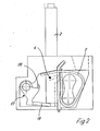
- connection device 1 shows a connection device 1 for connecting a conductor 2 by means of a Piercing contact 3, which has a tip 4 for penetrating a conductor insulation 16 and for contacting the line wires 15.
- the head 2 is by means of a tension spring 5 automatically pulled onto the tip 4, so that this first the Penetrating insulation 16 and then into the bundle of wires 15th penetrates.
- This connection device 1 is suitable for use in electrical Devices of all kinds such as terminal blocks, switching devices and the like.
- the tension spring 5 has a loop-shaped section 6, with which it connects to a Busbar 7 is attached.
- the loop-shaped section 6 is included free end 8, which has a recess 9 as a conductor opening / clamping space, which surrounds the busbar 7.
- the piercing contact 3 with the tip 4 is on the Busbar 7 arranged. It can also be punched out directly from the busbar 7 and be turned away from it.
- the tip 4 can also be flattened and have small cutting edges.
- connection device 1 is arranged here in an insulating housing 10, which a conductor insertion opening 11 for inserting the conductor 2 and a further insertion opening 13 for inserting an actuating tool, for example one Has screwdriver 14.
- FIGS. 1 and 2 An advantage of the arrangement of FIGS. 1 and 2 is that the connecting device a locking and release device 17 is assigned, which the tension spring in locked in their closed position, in which the conductor 2 in the conductor insertion opening 11 can be guided into the recess 9.
- the locking and triggering device 17 is here as in the insulating housing 10 rotatably mounted rotating element 18 with bearing 29 designed as a triggering device, which has a resilient arm 19 which is integral with a projection 20 is connected, which acts as a latch.
- the tension spring 5 When the tension spring 5 is compressed, the tension spring 5 becomes from the free end 8 the pin-like, bevelled projection 20 swept over, so that this resilient Arm 19 pressed down or deformed elastically, which is in the housing, here in the insulating housing 10 supports until the projection 20 snaps into the recess 9. This locks the tension spring 5 in the compressed "wiring position".
- the protrusion 20 is dimensioned such that the conductor 2 is also in the recess next to it 9 is insertable.
- the tension spring 5 is in turn released so that it pulls the conductor 2 pulls in the direction of the tip 4, where the conductor insulation 16 automatically pierced and / or cut and the line wires 15 are contacted (Fig. 2).
- connection device with the Locking and triggering device 17 with the aid of the screwdriver or when installing with a structurally simple and reliable manner in a "trap-like" State is set in which wiring without an operating tool is possible (Fig. 1).
- the tip 4 of the piercing contact 3 is molded directly onto the busbar 7 or punched out of this.
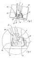
- the conductor 2 is in openings 21 in an insulating housing 10 pivotally mounted rotary actuator 22 insertable and such by turning towards and away from the piercing contact 3.
- U-shaped spring is used in a simple manner 23 for wiring the connection device.
- the U-shaped spring catches between its free ends 24, 25, the busbar 7 and the rotary actuator 22 a. It is designed to move these elements towards each other for wiring.
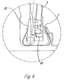
- the locking and triggering device 17 is here as on the insulating housing integrally formed, resilient arm 19 which is in the locked state supported on the rotary actuator and by inserting the Head is moved in the direction of a slot 27 in the rotary actuator 22 (Fig. 4). As soon as the arm 19 reaches the height of the slot 27 (FIG. 5), it dips into the slot 27 a. Here, the spring 23 contracts and rotates the rotary actuator 22 in the direction of the piercing contact 3, so that the connecting device is wired (Fig. 5).
- the connecting device can be returned to the starting position moved and de-energized and "cocked" again.
Landscapes
- Coupling Device And Connection With Printed Circuit (AREA)
- Connections By Means Of Piercing Elements, Nuts, Or Screws (AREA)
- Multi-Conductor Connections (AREA)
- Connections Arranged To Contact A Plurality Of Conductors (AREA)
Abstract
Description
- Fig. 1, 2
- zwei aufeinanderfolgende Betriebszustände beim Beschalten einer ersten Anschlussvorrichtung mit Piercingkontakt; und
- Fig. 3 - 6
- verschiedenen Ansichten und aufeinanderfolgende Betriebszustände beim Beschalten einer zweiten Anschlussvorrichtung mit Piercingkontakt.
- Anschlussvorrichtung
- 1
- Leiter
- 2
- Piercingkontakt
- 3
- Spitze
- 4
- Zugfeder
- 5
- schlaufenförmiger Abschnitt
- 6
- Stromschiene
- 7
- freies Ende
- 8
- Ausnehmung
- 9
- Isolierstoffgehäuse
- 10
- Leitereinführöffnung
- 11
- Einführöffnung
- 13
- Schraubendreher
- 14
- Leitungsadern
- 15
- Leiterisolierung
- 16
- Verriegelungs- und Auslösevorrichtung
- 17
- Drehelement
- 18
- Arm
- 19
- Vorsprung
- 20
- Öffnungen
- 21
- Betätigungsdrehelement
- 22
- Überfeder
- 23
- Freie Enden
- 24, 25
- Arm
- 26
- Schlitz
- 27
- Öffnung
- 28
- Lager
- 29
Claims (11)
- Anschlussvorrichtung (1) zum Anschluss eines Leiters (2) mit einer Leiterisolierung (16) und wenigstens einer Leitungsader (15) aufweist,a) mit einem selbstauslösenden Piercingkontakt (3), welcher eine Spitze (4) zum Durchdringen der Leiterisolierung (16) und zum Kontaktieren der Leitungsader(n) (15) aufweist,b) wobei ein federbetätigter Mechanismus zur selbsttätigen Beschaltung des Leiters vorgesehen ist, der eine Feder (5,23) aufweist, welche dazu ausgelegt ist, den Leiter (2) selbsttätig auf den Piercingkontakt (3) zu ziehen,c) wobei dem federbetätigten Mechanismus eine Verriegelungs- und Auslöseeinrichtung (17) zugeordnet ist, undd) wobei die Feder als Zugfeder (5) oder als U-förmige Überfeder (23) ausgebildet ist.
- Anschlussvorrichtung (1) nach Anspruch 1, dadurch gekennzeichnet, die Verriegelungs- und Auslösevorrichtung (17) als Drehelement (18) ausgebildet ist, das einen federnd nachgiebigen Arm (19) aufweist, der sich in einem Gehäuse (10) abstützt und der mit einem rastnasenartigen Vorsprung (20) verbunden ist, der zum Eingriff in eine Ausnehmung (9) der Feder (5) ausgelegt ist.
- Anschlussvorrichtung nach Anspruch 2, dadurch gekennzeichnet, dass der Vorsprung (20) zum Eingriff in die Ausnehmung (9) in der Stromschiene (7) ausgelegt ist.
- Anschlussvorrichtung nach einem der vorstehenden Ansprüche, dadurch gekennzeichnet, dass der Vorsprung (20) angeschrägt ausgebildet ist.
- Anschlussvorrichtung nach einem der vorstehenden Ansprüche, dadurch gekennzeichnet, dass der Vorsprung (20) derart bemessen ist, dass neben ihm der Leiter (2) in die Ausnehmung (9) einführbar ist.
- Anschlussvorrichtung nach einem der vorstehenden Ansprüche, dadurch gekennzeichnet, dass die Zugfeder (5) einen schlaufenförmigen Abschnitt (6) aufweist, mit dem sie an einer Stromschiene (7) angeordnet ist, wobei sich an den schlaufenförmigen Abschnitt (6) ein freies Ende (8) anschließt, welches eine Ausnehmung (9) aufweist, welche das freie Ende der Stromschiene (7) einfasst und welches zur Aufnahme des Leiters (2) nach dem Zusammenpressen der Zugfeder (5) dient.
- Anschlussvorrichtung nach einem der vorstehenden Ansprüche, dadurch gekennzeichnet, dass die Anschlussvorrichtung (1) in einem Isolierstoffgehäuse (10) angeordnet ist, welches eine Leitereinführöffnung (11) zum Einführen des Leiters (2) und eine weitere Einführöffnung (13) zum Einführen eines Betätigungswerkzeugs (14) aufweist, wobei die Ausnehmung (9) der Zugfeder (5) mittels des Betätigungswerkzeugs (14) unter die Leitereinführöffnung (11) führbar ist, so dass ein Leiter (2) in die Ausnehmung (9) einführbar ist und wobei sich der Arm (19) bis unterhalb der Ausnehmung (9) erstreckt.
- Anschlussvorrichtung nach einem der vorstehenden Ansprüche, dadurch gekennzeichnet, dass die Spitze (4) des Piercingkontakts (3) direkt an die Stromschiene (7) angeformt ist.
- Anschlussvorrichtung nach einem der vorstehenden Ansprüche, dadurch gekennzeichnet, dass die U-förmige Überfeder (23) zwischen ihren freien Enden (24, 25) die Stromschiene (7) mit der Spitze (4) und das Betätigungsdrehelement (22) einfasst und dazu ausgelegt ist, diese Elemente zum Beschalten selbsttätig aufeinander zu zu bewegen.
- Anschlussvorrichtung nach einem der vorstehenden Ansprüche, dadurch gekennzeichnet, dass die Verriegelungs- und Auslösevorrichtung (17) als ein an ein Gehäuse (10) angeformter, federnd nachgiebiger Arm (19) ausgebildet ist, welcher sich im Verriegelungszustand an dem Betätigungsdrehelement (22) abstützt und durch das Einführen des Leiters in Richtung eines Schlitzes (27) im Betätigungsdrehelement (22) bewegbar ist, bis er in diesen eingreift.
- Anschlussvorrichtung nach einem der vorstehenden Ansprüche, dadurch gekennzeichnet, dass das Betätigungselement (22) mit der Öffnung (28) zum Entschalten in die Ausgangslage zurück bewegbar ist.
Applications Claiming Priority (2)
| Application Number | Priority Date | Filing Date | Title |
|---|---|---|---|
| DE20305156U DE20305156U1 (de) | 2003-03-28 | 2003-03-28 | Anschlußvorrichtung mit selbstauslösendem Piercingkontakt |
| DE20305156U | 2003-03-28 |
Publications (2)
| Publication Number | Publication Date |
|---|---|
| EP1463152A1 true EP1463152A1 (de) | 2004-09-29 |
| EP1463152B1 EP1463152B1 (de) | 2006-12-27 |
Family
ID=32798260
Family Applications (1)
| Application Number | Title | Priority Date | Filing Date |
|---|---|---|---|
| EP04400010A Expired - Lifetime EP1463152B1 (de) | 2003-03-28 | 2004-03-04 | Anschlussvorrichtung mit selbstauslösendem Piercingkontakt |
Country Status (3)
| Country | Link |
|---|---|
| EP (1) | EP1463152B1 (de) |
| AT (1) | ATE349782T1 (de) |
| DE (2) | DE20305156U1 (de) |
Cited By (5)
| Publication number | Priority date | Publication date | Assignee | Title |
|---|---|---|---|---|
| AT15515U1 (de) * | 2016-06-13 | 2017-11-15 | Benedict Gmbh | Federkraftklemme |
| CN114830441A (zh) * | 2019-12-19 | 2022-07-29 | 菲尼克斯电气公司 | 连接组件,连接装置以及电子设备 |
| US20240030640A1 (en) * | 2022-07-19 | 2024-01-25 | Weidmüller Interface GmbH & Co. KG | Row of plug connectors |
| EP4376221A1 (de) * | 2022-11-22 | 2024-05-29 | Phoenix Contact GmbH & Co KG | Anschlussanordnung sowie anschlussklemme |
| DE202024103826U1 (de) * | 2024-07-10 | 2025-10-23 | WAGO Verwaltungsgesellschaft mit beschränkter Haftung | Leiteranschlussklemme zum Anschluss eines elektrischen Leiters |
Families Citing this family (9)
| Publication number | Priority date | Publication date | Assignee | Title |
|---|---|---|---|---|
| FR2875059B1 (fr) * | 2004-09-08 | 2006-12-22 | Abb Entrelec Soc Par Actions S | Dispositif de raccordement a ressort pour fil conducteur |
| DE102010054679B4 (de) * | 2010-12-15 | 2012-08-30 | Bjb Gmbh & Co. Kg | Klemmkontakt |
| DE102017106784B3 (de) | 2017-03-29 | 2018-10-04 | Phoenix Contact Gmbh & Co. Kg | Leiteranschlusseinrichtung |
| DE102019127464B3 (de) * | 2019-10-11 | 2021-03-25 | Phoenix Contact Gmbh & Co. Kg | Anschlusseinrichtung zum Anschließen einer elektrischen Leitung |
| DE102019128819A1 (de) * | 2019-10-25 | 2021-04-29 | Phoenix Contact Gmbh & Co. Kg | Anschlusseinrichtung zum Anschließen einer elektrischen Leitung |
| DE202023105329U1 (de) * | 2023-09-14 | 2024-12-19 | WAGO Verwaltungsgesellschaft mit beschränkter Haftung | Federkraftklemmanschluss und Leiteranschlussklemme |
| DE202023105327U1 (de) * | 2023-09-14 | 2024-12-19 | WAGO Verwaltungsgesellschaft mit beschränkter Haftung | Federkraftklemmanschluss und Leiteranschlussklemme |
| DE202024105988U1 (de) * | 2024-10-18 | 2026-02-26 | WAGO Verwaltungsgesellschaft mit beschränkter Haftung | Leiteranschlussklemme und elektrischer Steckverbinder |
| DE202024106715U1 (de) * | 2024-11-21 | 2026-04-02 | WAGO Verwaltungsgesellschaft mit beschränkter Haftung | Federkraftklemmanschluss und Leiteranschlussklemme |
Citations (5)
| Publication number | Priority date | Publication date | Assignee | Title |
|---|---|---|---|---|
| EP0108235A1 (de) * | 1982-10-13 | 1984-05-16 | Rafi GmbH & Co Elektrotechnische Spezialfabrik | Vorrichtung zur schraubenlosen Verbindung zweier Teile |
| DE3302372A1 (de) * | 1983-01-25 | 1984-07-26 | WAGO Verwaltungsgesellschaft mbH, 4950 Minden | Schraubenlose klemme |
| GB2158303A (en) * | 1984-04-27 | 1985-11-06 | Woertz Oskar | Insulation piercing terminal block |
| DE19737947A1 (de) * | 1997-08-30 | 1999-03-04 | Georg Schlegel Gmbh | Reihenklemme zum abisolierungsfreien Anschluß isolierter Leiter |
| DE19825629A1 (de) * | 1998-06-08 | 1999-12-16 | Siemens Ag | Federkraftklemme |
Family Cites Families (5)
| Publication number | Priority date | Publication date | Assignee | Title |
|---|---|---|---|---|
| DE3727091C1 (de) * | 1987-08-14 | 1989-02-02 | Wieland Elek Sche Ind Gmbh F | Schraubenlose Anschluss- und/oder Verbindungsklemme |
| DE19604615C1 (de) * | 1996-02-08 | 1997-06-12 | Siemens Ag | Kontaktierungseinrichtung |
| DE19835459C2 (de) * | 1998-08-06 | 2002-12-19 | Phoenix Contact Gmbh & Co | Anschlußklemme für elektrische Leiter |
| DE20000628U1 (de) * | 1999-01-18 | 2000-06-29 | Wieland Electric GmbH, 96052 Bamberg | Anschlussklemme |
| DE10007090A1 (de) * | 2000-02-16 | 2001-08-23 | Schlegel Georg Gmbh & Co | Anschlussklemme für einen isolierten Leiter |
-
2003
- 2003-03-28 DE DE20305156U patent/DE20305156U1/de not_active Expired - Lifetime
-
2004
- 2004-03-04 EP EP04400010A patent/EP1463152B1/de not_active Expired - Lifetime
- 2004-03-04 AT AT04400010T patent/ATE349782T1/de not_active IP Right Cessation
- 2004-03-04 DE DE502004002413T patent/DE502004002413D1/de not_active Expired - Lifetime
Patent Citations (5)
| Publication number | Priority date | Publication date | Assignee | Title |
|---|---|---|---|---|
| EP0108235A1 (de) * | 1982-10-13 | 1984-05-16 | Rafi GmbH & Co Elektrotechnische Spezialfabrik | Vorrichtung zur schraubenlosen Verbindung zweier Teile |
| DE3302372A1 (de) * | 1983-01-25 | 1984-07-26 | WAGO Verwaltungsgesellschaft mbH, 4950 Minden | Schraubenlose klemme |
| GB2158303A (en) * | 1984-04-27 | 1985-11-06 | Woertz Oskar | Insulation piercing terminal block |
| DE19737947A1 (de) * | 1997-08-30 | 1999-03-04 | Georg Schlegel Gmbh | Reihenklemme zum abisolierungsfreien Anschluß isolierter Leiter |
| DE19825629A1 (de) * | 1998-06-08 | 1999-12-16 | Siemens Ag | Federkraftklemme |
Cited By (6)
| Publication number | Priority date | Publication date | Assignee | Title |
|---|---|---|---|---|
| AT15515U1 (de) * | 2016-06-13 | 2017-11-15 | Benedict Gmbh | Federkraftklemme |
| CN114830441A (zh) * | 2019-12-19 | 2022-07-29 | 菲尼克斯电气公司 | 连接组件,连接装置以及电子设备 |
| CN114830441B (zh) * | 2019-12-19 | 2025-09-30 | 菲尼克斯电气公司 | 连接组件,连接装置以及电子设备 |
| US20240030640A1 (en) * | 2022-07-19 | 2024-01-25 | Weidmüller Interface GmbH & Co. KG | Row of plug connectors |
| EP4376221A1 (de) * | 2022-11-22 | 2024-05-29 | Phoenix Contact GmbH & Co KG | Anschlussanordnung sowie anschlussklemme |
| DE202024103826U1 (de) * | 2024-07-10 | 2025-10-23 | WAGO Verwaltungsgesellschaft mit beschränkter Haftung | Leiteranschlussklemme zum Anschluss eines elektrischen Leiters |
Also Published As
| Publication number | Publication date |
|---|---|
| DE20305156U1 (de) | 2004-08-19 |
| ATE349782T1 (de) | 2007-01-15 |
| DE502004002413D1 (de) | 2007-02-08 |
| EP1463152B1 (de) | 2006-12-27 |
Similar Documents
| Publication | Publication Date | Title |
|---|---|---|
| EP1641078B1 (de) | Elektrische Anschluss- oder Verbindungsklemme | |
| DE3514097C2 (de) | Verbindungsklemme für elektrische Leiter | |
| DE102008039232B4 (de) | Elektrische Anschlußklemme | |
| EP2395605B1 (de) | Federklemmelement und Reihenklemme | |
| EP3963673B1 (de) | Federkraftklemme für leiter | |
| EP3766132A1 (de) | Federkraftklemme für leiter | |
| EP1251590B1 (de) | Elektrische Klemme | |
| EP1463152B1 (de) | Anschlussvorrichtung mit selbstauslösendem Piercingkontakt | |
| EP1111720A1 (de) | Schraubenlose Anschlussklemme | |
| DE4408985B4 (de) | Elektrische Einrichtung, insbesondere Reihenklemme, mit einer Klemme für eine Schnellverbindung | |
| DE202006009460U1 (de) | Anschlussvorrichtung für Leiter | |
| DE19835459C2 (de) | Anschlußklemme für elektrische Leiter | |
| EP2001086B1 (de) | Schraubenlose Anschlussklemme | |
| EP1207588A1 (de) | Elektrischer Verbinder für flexible Flachkabel oder flexible Leiterplatten | |
| DE4433983A1 (de) | Anschlußklemme für elektrische Installationen | |
| DE2519436A1 (de) | Verfahren und vorrichtung zur befestigung von anschluessen an einem flachleiterkabel | |
| DE19627209C1 (de) | Anschlußvorrichtung für nichtabisolierte Leiter | |
| EP3261183A1 (de) | Federkontakt | |
| EP1753087B1 (de) | Elektrische Klemme | |
| EP3813198A1 (de) | Anschlusseinrichtung zum anschliessen einer elektrischen leitung | |
| EP1523065B1 (de) | Elektrische Klemme | |
| EP2819246B1 (de) | Anschlussvorrichtung, insbesondere Schaltgerät, mit einer Federzugklemme und einem Antrieb zum Betätigen der Federzugklemme | |
| DE10119652A1 (de) | Schraubenlose Anschlussklemme | |
| EP1555724A1 (de) | Schraubenlose Leiteranschlussklemme | |
| DE2802133C2 (de) | Schnappschalter |
Legal Events
| Date | Code | Title | Description |
|---|---|---|---|
| PUAI | Public reference made under article 153(3) epc to a published international application that has entered the european phase |
Free format text: ORIGINAL CODE: 0009012 |
|
| AK | Designated contracting states |
Kind code of ref document: A1 Designated state(s): AT BE BG CH CY CZ DE DK EE ES FI FR GB GR HU IE IT LI LU MC NL PL PT RO SE SI SK TR |
|
| AX | Request for extension of the european patent |
Extension state: AL HR LT LV MK |
|
| 17P | Request for examination filed |
Effective date: 20050114 |
|
| 17Q | First examination report despatched |
Effective date: 20050308 |
|
| AKX | Designation fees paid |
Designated state(s): AT BE BG CH CY CZ DE DK EE ES FI FR GB GR HU IE IT LI LU MC NL PL PT RO SE SI SK TR |
|
| GRAP | Despatch of communication of intention to grant a patent |
Free format text: ORIGINAL CODE: EPIDOSNIGR1 |
|
| GRAS | Grant fee paid |
Free format text: ORIGINAL CODE: EPIDOSNIGR3 |
|
| GRAA | (expected) grant |
Free format text: ORIGINAL CODE: 0009210 |
|
| AK | Designated contracting states |
Kind code of ref document: B1 Designated state(s): AT BE BG CH CY CZ DE DK EE ES FI FR GB GR HU IE IT LI LU MC NL PL PT RO SE SI SK TR |
|
| PG25 | Lapsed in a contracting state [announced via postgrant information from national office to epo] |
Ref country code: IT Free format text: LAPSE BECAUSE OF FAILURE TO SUBMIT A TRANSLATION OF THE DESCRIPTION OR TO PAY THE FEE WITHIN THE PRESCRIBED TIME-LIMIT;WARNING: LAPSES OF ITALIAN PATENTS WITH EFFECTIVE DATE BEFORE 2007 MAY HAVE OCCURRED AT ANY TIME BEFORE 2007. THE CORRECT EFFECTIVE DATE MAY BE DIFFERENT FROM THE ONE RECORDED. Effective date: 20061227 Ref country code: PL Free format text: LAPSE BECAUSE OF FAILURE TO SUBMIT A TRANSLATION OF THE DESCRIPTION OR TO PAY THE FEE WITHIN THE PRESCRIBED TIME-LIMIT Effective date: 20061227 Ref country code: RO Free format text: LAPSE BECAUSE OF FAILURE TO SUBMIT A TRANSLATION OF THE DESCRIPTION OR TO PAY THE FEE WITHIN THE PRESCRIBED TIME-LIMIT Effective date: 20061227 Ref country code: SI Free format text: LAPSE BECAUSE OF FAILURE TO SUBMIT A TRANSLATION OF THE DESCRIPTION OR TO PAY THE FEE WITHIN THE PRESCRIBED TIME-LIMIT Effective date: 20061227 Ref country code: NL Free format text: LAPSE BECAUSE OF FAILURE TO SUBMIT A TRANSLATION OF THE DESCRIPTION OR TO PAY THE FEE WITHIN THE PRESCRIBED TIME-LIMIT Effective date: 20061227 Ref country code: CZ Free format text: LAPSE BECAUSE OF FAILURE TO SUBMIT A TRANSLATION OF THE DESCRIPTION OR TO PAY THE FEE WITHIN THE PRESCRIBED TIME-LIMIT Effective date: 20061227 Ref country code: IE Free format text: LAPSE BECAUSE OF FAILURE TO SUBMIT A TRANSLATION OF THE DESCRIPTION OR TO PAY THE FEE WITHIN THE PRESCRIBED TIME-LIMIT Effective date: 20061227 Ref country code: SK Free format text: LAPSE BECAUSE OF FAILURE TO SUBMIT A TRANSLATION OF THE DESCRIPTION OR TO PAY THE FEE WITHIN THE PRESCRIBED TIME-LIMIT Effective date: 20061227 Ref country code: FI Free format text: LAPSE BECAUSE OF FAILURE TO SUBMIT A TRANSLATION OF THE DESCRIPTION OR TO PAY THE FEE WITHIN THE PRESCRIBED TIME-LIMIT Effective date: 20061227 Ref country code: DK Free format text: LAPSE BECAUSE OF FAILURE TO SUBMIT A TRANSLATION OF THE DESCRIPTION OR TO PAY THE FEE WITHIN THE PRESCRIBED TIME-LIMIT Effective date: 20061227 |
|
| REG | Reference to a national code |
Ref country code: GB Ref legal event code: FG4D Free format text: NOT ENGLISH |
|
| REG | Reference to a national code |
Ref country code: IE Ref legal event code: FG4D Free format text: LANGUAGE OF EP DOCUMENT: GERMAN |
|
| REF | Corresponds to: |
Ref document number: 502004002413 Country of ref document: DE Date of ref document: 20070208 Kind code of ref document: P |
|
| PG25 | Lapsed in a contracting state [announced via postgrant information from national office to epo] |
Ref country code: BG Free format text: LAPSE BECAUSE OF FAILURE TO SUBMIT A TRANSLATION OF THE DESCRIPTION OR TO PAY THE FEE WITHIN THE PRESCRIBED TIME-LIMIT Effective date: 20070327 Ref country code: SE Free format text: LAPSE BECAUSE OF FAILURE TO SUBMIT A TRANSLATION OF THE DESCRIPTION OR TO PAY THE FEE WITHIN THE PRESCRIBED TIME-LIMIT Effective date: 20070327 |
|
| PG25 | Lapsed in a contracting state [announced via postgrant information from national office to epo] |
Ref country code: ES Free format text: LAPSE BECAUSE OF FAILURE TO SUBMIT A TRANSLATION OF THE DESCRIPTION OR TO PAY THE FEE WITHIN THE PRESCRIBED TIME-LIMIT Effective date: 20070407 |
|
| PG25 | Lapsed in a contracting state [announced via postgrant information from national office to epo] |
Ref country code: PT Free format text: LAPSE BECAUSE OF FAILURE TO SUBMIT A TRANSLATION OF THE DESCRIPTION OR TO PAY THE FEE WITHIN THE PRESCRIBED TIME-LIMIT Effective date: 20070528 |
|
| NLV1 | Nl: lapsed or annulled due to failure to fulfill the requirements of art. 29p and 29m of the patents act | ||
| GBV | Gb: ep patent (uk) treated as always having been void in accordance with gb section 77(7)/1977 [no translation filed] |
Effective date: 20061227 |
|
| EN | Fr: translation not filed | ||
| PLBE | No opposition filed within time limit |
Free format text: ORIGINAL CODE: 0009261 |
|
| STAA | Information on the status of an ep patent application or granted ep patent |
Free format text: STATUS: NO OPPOSITION FILED WITHIN TIME LIMIT |
|
| PG25 | Lapsed in a contracting state [announced via postgrant information from national office to epo] |
Ref country code: GB Free format text: LAPSE BECAUSE OF FAILURE TO SUBMIT A TRANSLATION OF THE DESCRIPTION OR TO PAY THE FEE WITHIN THE PRESCRIBED TIME-LIMIT Effective date: 20061227 |
|
| 26N | No opposition filed |
Effective date: 20070928 |
|
| BERE | Be: lapsed |
Owner name: WEIDMULLER INTERFACE G.M.B.H. & CO. KG Effective date: 20070331 |
|
| PG25 | Lapsed in a contracting state [announced via postgrant information from national office to epo] |
Ref country code: BE Free format text: LAPSE BECAUSE OF NON-PAYMENT OF DUE FEES Effective date: 20070331 |
|
| PG25 | Lapsed in a contracting state [announced via postgrant information from national office to epo] |
Ref country code: GR Free format text: LAPSE BECAUSE OF FAILURE TO SUBMIT A TRANSLATION OF THE DESCRIPTION OR TO PAY THE FEE WITHIN THE PRESCRIBED TIME-LIMIT Effective date: 20070328 Ref country code: FR Free format text: LAPSE BECAUSE OF FAILURE TO SUBMIT A TRANSLATION OF THE DESCRIPTION OR TO PAY THE FEE WITHIN THE PRESCRIBED TIME-LIMIT Effective date: 20070817 |
|
| PG25 | Lapsed in a contracting state [announced via postgrant information from national office to epo] |
Ref country code: AT Free format text: LAPSE BECAUSE OF NON-PAYMENT OF DUE FEES Effective date: 20070304 |
|
| REG | Reference to a national code |
Ref country code: CH Ref legal event code: PL |
|
| PG25 | Lapsed in a contracting state [announced via postgrant information from national office to epo] |
Ref country code: FR Free format text: LAPSE BECAUSE OF FAILURE TO SUBMIT A TRANSLATION OF THE DESCRIPTION OR TO PAY THE FEE WITHIN THE PRESCRIBED TIME-LIMIT Effective date: 20061227 |
|
| PG25 | Lapsed in a contracting state [announced via postgrant information from national office to epo] |
Ref country code: LI Free format text: LAPSE BECAUSE OF NON-PAYMENT OF DUE FEES Effective date: 20080331 Ref country code: CH Free format text: LAPSE BECAUSE OF NON-PAYMENT OF DUE FEES Effective date: 20080331 Ref country code: EE Free format text: LAPSE BECAUSE OF FAILURE TO SUBMIT A TRANSLATION OF THE DESCRIPTION OR TO PAY THE FEE WITHIN THE PRESCRIBED TIME-LIMIT Effective date: 20061227 |
|
| PG25 | Lapsed in a contracting state [announced via postgrant information from national office to epo] |
Ref country code: CY Free format text: LAPSE BECAUSE OF FAILURE TO SUBMIT A TRANSLATION OF THE DESCRIPTION OR TO PAY THE FEE WITHIN THE PRESCRIBED TIME-LIMIT Effective date: 20061227 Ref country code: LU Free format text: LAPSE BECAUSE OF NON-PAYMENT OF DUE FEES Effective date: 20070304 |
|
| PG25 | Lapsed in a contracting state [announced via postgrant information from national office to epo] |
Ref country code: TR Free format text: LAPSE BECAUSE OF FAILURE TO SUBMIT A TRANSLATION OF THE DESCRIPTION OR TO PAY THE FEE WITHIN THE PRESCRIBED TIME-LIMIT Effective date: 20061227 Ref country code: HU Free format text: LAPSE BECAUSE OF FAILURE TO SUBMIT A TRANSLATION OF THE DESCRIPTION OR TO PAY THE FEE WITHIN THE PRESCRIBED TIME-LIMIT Effective date: 20070628 |
|
| PG25 | Lapsed in a contracting state [announced via postgrant information from national office to epo] |
Ref country code: MC Free format text: LAPSE BECAUSE OF NON-PAYMENT OF DUE FEES Effective date: 20070331 |
|
| PGFP | Annual fee paid to national office [announced via postgrant information from national office to epo] |
Ref country code: DE Payment date: 20140319 Year of fee payment: 11 |
|
| REG | Reference to a national code |
Ref country code: DE Ref legal event code: R119 Ref document number: 502004002413 Country of ref document: DE |
|
| PG25 | Lapsed in a contracting state [announced via postgrant information from national office to epo] |
Ref country code: DE Free format text: LAPSE BECAUSE OF NON-PAYMENT OF DUE FEES Effective date: 20151001 |