EP1462308B1 - Fahrzeugkarosserie mit einem Scheinwerfergehäuse mit einer integrierten Strukturstrebe - Google Patents
Fahrzeugkarosserie mit einem Scheinwerfergehäuse mit einer integrierten Strukturstrebe Download PDFInfo
- Publication number
- EP1462308B1 EP1462308B1 EP04006628A EP04006628A EP1462308B1 EP 1462308 B1 EP1462308 B1 EP 1462308B1 EP 04006628 A EP04006628 A EP 04006628A EP 04006628 A EP04006628 A EP 04006628A EP 1462308 B1 EP1462308 B1 EP 1462308B1
- Authority
- EP
- European Patent Office
- Prior art keywords
- strut
- vehicle body
- headlamp housing
- vehicle
- structural
- Prior art date
- Legal status (The legal status is an assumption and is not a legal conclusion. Google has not performed a legal analysis and makes no representation as to the accuracy of the status listed.)
- Expired - Lifetime
Links
- 210000002105 tongue Anatomy 0.000 claims 2
- 238000010276 construction Methods 0.000 description 1
- 230000000694 effects Effects 0.000 description 1
- 238000001746 injection moulding Methods 0.000 description 1
- 238000009434 installation Methods 0.000 description 1
- 239000000725 suspension Substances 0.000 description 1
Images
Classifications
-
- B—PERFORMING OPERATIONS; TRANSPORTING
- B60—VEHICLES IN GENERAL
- B60Q—ARRANGEMENT OF SIGNALLING OR LIGHTING DEVICES, THE MOUNTING OR SUPPORTING THEREOF OR CIRCUITS THEREFOR, FOR VEHICLES IN GENERAL
- B60Q1/00—Arrangement of optical signalling or lighting devices, the mounting or supporting thereof or circuits therefor
- B60Q1/02—Arrangement of optical signalling or lighting devices, the mounting or supporting thereof or circuits therefor the devices being primarily intended to illuminate the way ahead or to illuminate other areas of way or environments
- B60Q1/04—Arrangement of optical signalling or lighting devices, the mounting or supporting thereof or circuits therefor the devices being primarily intended to illuminate the way ahead or to illuminate other areas of way or environments the devices being headlights
- B60Q1/0408—Arrangement of optical signalling or lighting devices, the mounting or supporting thereof or circuits therefor the devices being primarily intended to illuminate the way ahead or to illuminate other areas of way or environments the devices being headlights built into the vehicle body, e.g. details concerning the mounting of the headlamps on the vehicle body
-
- B—PERFORMING OPERATIONS; TRANSPORTING
- B60—VEHICLES IN GENERAL
- B60Q—ARRANGEMENT OF SIGNALLING OR LIGHTING DEVICES, THE MOUNTING OR SUPPORTING THEREOF OR CIRCUITS THEREFOR, FOR VEHICLES IN GENERAL
- B60Q1/00—Arrangement of optical signalling or lighting devices, the mounting or supporting thereof or circuits therefor
- B60Q1/02—Arrangement of optical signalling or lighting devices, the mounting or supporting thereof or circuits therefor the devices being primarily intended to illuminate the way ahead or to illuminate other areas of way or environments
- B60Q1/04—Arrangement of optical signalling or lighting devices, the mounting or supporting thereof or circuits therefor the devices being primarily intended to illuminate the way ahead or to illuminate other areas of way or environments the devices being headlights
- B60Q1/0491—Shock absorbing devices therefor
- B60Q1/0495—Frangible brackets
Definitions
- the invention relates to a vehicle body with a headlight housing according to the preamble of claim 1.
- the headlamp housing consists essentially of a plastic, since the vehicle weight should not be unnecessarily increased by the headlamp.
- the necessary support and sufficient rigidity receives the headlamp housing by placing it in a closed, the housing on all sides comprehensive frame in the vehicle body z. B. is used in the vehicle front.
- the assembly of the headlight housing is usually cumbersome.
- the invention is thus based on the problem of providing a vehicle body with a receptacle for the headlight housing, in which the headlight housing is easy to assemble. For necessary changes to the vehicle body should not cause the Stiffness of the body suffers. In addition, a stable alignment of the headlight housing in the vehicle body must continue to be ensured.
- the invention provides a vehicle body according to the preamble of claim 1, which is characterized in that the front strut ends approximately in an imaginary longitudinal extension of the side strut and that there is a gap between the end of the side strut and the front strut, in the structure strut of the headlamp housing extending substantially in the vehicle longitudinal direction is used bridging the gap and that the ends of the front strut and the side strut are fastened to the side member via a respective high support and that the side member and the two high supports form the partially open frame for receiving the headlight housing ,
- a supporting function performing part of the vehicle body is integrated in the headlight housing. Only with the installation of the provided with a structure strut headlight housing thus the body is completed. This simplifies assembly, since the tabs are easily accessible and are not within the closed frame on the vehicle body. Also, the assembly of the vehicle body is simplified because the frame, as long as the headlight housing is not installed, partially open, so that all welds are easy to reach.
- the base plate may be suspended from the structural strut.
- the structure strut may be formed integrally with the headlight housing. This has the advantage that housing and structure strut can be produced in one operation, for example by injection molding.
- the structure strut can also be a separate component which is held and fixed in a guide on the headlight housing.
- the fastenings of the tabs on the body can be designed as predetermined breaking points or as deformation elements. This ensures that z. B. in a pedestrian impact, the body easily yields, if missing because of the dissolved or yielding at the predetermined breaking points attachment the stiffening effect of the structural strut.
- the structure strut itself can form a deformation element that deforms in an impact, z. B. bends and absorbs kinetic energy.
- the structural strut of the headlight housing is bolted to the partially open frame.
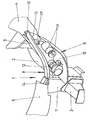
- the single figure shows - partly in schematic representation - the front left corner of a vehicle body with an inserted headlight.
- the vehicle body 1 is based on a longitudinal member 2, extending from the front of the vehicle (in the front Part of the image) extends to the passenger compartment, not shown. At its front end, a crash box 3 is attached to which the front bumper is screwed.
- a side strut 4 which is fastened with its front end via a high support 5 on the longitudinal member 2.
- the connection of the high support 5 with the side strut 4 serves as a support point for the suspension of the left front wheel, not shown.
- the front of the vehicle forms a front strut 6, which is attached via a further high support 7 at the end of the longitudinal member 2.
- the two high columns 5, 7 and the longitudinal members 2 form a U-shaped, upwardly open and thus partially open frame 8 for a headlight housing 9.
- the frame surface is only slightly inclined relative to a longitudinal axis of the vehicle, d. h., That the surface normal is directed substantially to the vehicle side.
- the headlight housing 9 which is shown only in part, consists of a base plate 10, on which a plurality of bulbs 11 are located, for. As a headlight for low beam and a headlight for high beam, in modular design. Via at least one holder 11 ', the base plate 10 is connected to a structural strut 12. Before the base plate 10 and in front of the structure strut 12 is a lens 13, which is indicated schematically here.
- the structural strut 12 is an integral part of the headlamp housing 9. Either it is designed in one piece with this or in a guide in the Headlight housing 9 held. In any case, the structure strut 12 is used with the headlight housing 9 together in the partially open frame 8. Thereafter, the two formed as tabs 14, 15 ends of the structure strut 12 are connected to the front strut 6 and 4 with the side strut. Thus, the structural strut closes the frame 8 and becomes part of the vehicle body 1 and assumes a supporting function, which is normally exerted by an upper frame part of a closed frame.
- the structure of the body is thus done in such a way that a part of the vehicle body 1 is first formed with the headlight housing 9. Thereafter, this part is used together with the headlight housing 9 in the vehicle body 1 and fixed there, so that a closed frame for the headlamp arises.
Landscapes
- Engineering & Computer Science (AREA)
- Mechanical Engineering (AREA)
- Lighting Device Outwards From Vehicle And Optical Signal (AREA)
- Body Structure For Vehicles (AREA)
Description
- Die Erfindung bezieht sich auf eine Fahrzeugkarosserie mit einem Scheinwerfergehäuse gemäß dem Oberbegriff des Anspruches 1.
- Eine derartige Fahrzeugkarosserie ist in der
WO 02/102645 - Die Erfindung beruht somit auf dem Problem eine Fahrzeugkarosserie mit einer Aufnahme für das Scheinwerfergehäuse zu schaffen, bei dem das Scheinwerfergehäuse leicht zu montieren ist. Dafür notwendige Änderungen an der Fahrzeugkarosserie sollen nicht dazu führen, dass die Steifigkeit der Karosserie leidet. Außerdem muss weiterhin eine stabile Ausrichtung des Scheinwerfergehäuses in der Fahrzeugkarosserie gewährleistet sein.
- Zur Lösung des Problems sieht die Erfindung eine Fahrzeugkarosserie gemäß dem Oberbegriff des Anspruchs 1 vor, die dadurch gekennzeichnet ist, dass die Frontstrebe in etwa in einer gedachten Längsverlängerung der Seitenstrebe endet und dass zwischen dem Ende der Seitenstrebe und der Frontstrebe eine Lücke vorhanden ist, in der die sich im Wesentlichen in Fahrzeuglängsrichtung erstreckende Strukturstrebe des Scheinwerfergehäuses die Lücke überbrückend eingesetzt ist und dass die Enden der Frontstrebe und der Seitenstrebe über jeweils eine Hochstütze an dem Längsträger befestigt sind und dass der Längsträger und die beiden Hochstützen den teiloffenen Rahmen zur Aufnahme des Scheinwerfergehäuses bilden.
- Auf diese Weise wird ein eine Stützfunktion ausübendes Teil der Fahrzeugkarosserie im Scheinwerfergehäuse integriert. Erst mit dem Einbau des mit einer Strukturstrebe versehenen Scheinwerfergehäuses wird somit die Karosserie komplettiert. Dies vereinfacht die Montage, da die Laschen leicht zugänglich sind und nicht innerhalb des geschlossenen Rahmens an der Fahrzeugkarosserie liegen. Auch der Zusammenbau der Fahrzeugkarosserie wird vereinfacht, da der Rahmen, solange das Scheinwerfergehäuse noch nicht eingebaut ist, teiloffen ist, so dass alle Schweißpunkte leicht zu erreichen sind.
- Vorzugsweise kann die Grundplatte hängend an der Strukturstrebe befestigt sein. Dies hat den Vorteil, dass das Scheinwerfergehäuse ausschließlich mit den Laschen der Strukturstrebe an der Fahrzeugkarosserie befestigt ist, d. h. es brauchen nur zwei Befestigungsoperationen durchgeführt werden. Da die Strukturstrebe eine gewisse Festigkeit benötigt, um die Karosserie zu versteifen, kann sie auch dem Scheinwerfergehäuse eine Stabilität geben, die für eine stets exakte Ausrichtung der Grundplatte notwendig ist.
- Die Strukturstrebe kann einteilig mit dem Scheinwerfergehäuse ausgebildet sein. Dies hat den Vorteil, dass Gehäuse und Strukturstrebe in einem Arbeitsgang zum Beispiel im Spritzgussverfahren hergestellt werden können.
- Die Strukturstrebe kann aber auch ein gesondertes Bauteil sein, das in einer Führung am Scheinwerfergehäuse gehalten und befestigt ist.
- Die Befestigungen der Laschen an der Karosserie können als Sollbruchstellen oder als Deformationselemente ausgelegt sein. Damit wird erreicht, dass z. B. bei einem Fußgängeraufprall die Karosserie leicht nachgibt, wenn wegen der an den Sollbruchstellen gelösten bzw. nachgebenden Befestigung die versteifende Wirkung der Strukturstrebe fehlt.
- Je nach Einbaulage kann die Strukturstrebe selbst ein Deformationselement bilden, das sich bei einem Aufprall verformt, sich z. B. durchbiegt und dabei Bewegungsenergie aufnimmt.
- Gemäß der Erfindung brauchen keine großen Änderungen an der Konstruktion einer vorhandenen Fahrzeugkarosserie vorgenommen zu werden. Lediglich die Seitenstrebe wird gekürzt, so dass sie sich nicht bis zur Front des Fahrzeuges erstreckt. Die verbleibende Lücke zur Frontstrebe wird durch die Strukturstrebe überbrückt.
- Vorzugsweise wird die Strukturstrebe des Scheinwerfergehäuses mit dem teiloffenen Rahmen verschraubt.
- Zur Erläuterung der Erfindung zeigt die einzige Figur - zum Teil in schematischer Darstellung - die vordere linke Ecke einer Fahrzeugkarosserie mit einem eingesetzten Scheinwerfer.
- Die Fahrzeugkarosserie 1 baut auf einen Längsträger 2 auf, der sich von der Fahrzeugfront (im vorderen Teil des Bildes) zur nicht gezeigten Fahrgastzelle erstreckt. An seinem vorderen Ende ist eine Crash-Box 3 befestigt, an der der vordere Stoßfänger angeschraubt wird.
- Oberhalb und parallel zum Längsträger 2 erstreckt sich eine Seitenstrebe 4, die mit ihrem vorderen Ende über eine Hochstütze 5 am Längsträger 2 befestigt ist. Die Verbindung der Hochstütze 5 mit der Seitenstrebe 4 dient als Abstützpunkt für die Radaufhängung des nicht gezeigten linken Vorderrades.
- Die Front des Fahrzeuges bildet eine Frontstrebe 6, die über eine weitere Hochstütze 7 am Ende des Längsträgers 2 befestigt ist.
- Die beiden Hochstützen 5, 7 sowie der Längsträger 2 bilden einen U-förmigen, nach oben offenen und somit teiloffenen Rahmen 8 für ein Scheinwerfergehäuse 9. Die Rahmenfläche ist dabei nur leicht gegenüber einer Längsachse des Fahrzeuges geneigt, d. h., dass die Flächennormale im Wesentlichen zur Fahrzeugseite gerichtet ist.
- Das Scheinwerfergehäuse 9, das nur zum Teil dargestellt ist, besteht aus einer Grundplatte 10, auf der sich mehrere Leuchtmittel 11 befinden, z. B. ein Scheinwerfer für Abblendlicht und ein Scheinwerfer für Fernlicht, in Modulbauweise. Über wenigstens einen Halter 11' ist die Grundplatte 10 mit einer Strukturstrebe 12 verbunden. Vor der Grundplatte 10 und vor der Strukturstrebe 12 befindet sich eine Streuscheibe 13, die hier schematisch angedeutet ist.
- Die Strukturstrebe 12 ist ein integraler Bestand des Scheinwerfergehäuses 9. Entweder ist sie einteilig mit diesem ausgeführt oder in einer Führung im Scheinwerfergehäuse 9 gehalten. Auf jeden Fall wird die Strukturstrebe 12 mit dem Scheinwerfergehäuse 9 zusammen in den teiloffenen Rahmen 8 eingesetzt. Danach werden die beiden als Laschen 14, 15 ausgeformten Enden der Strukturstrebe 12 mit der Frontstrebe 6 bzw. mit der Seitenstrebe 4 verbunden. Damit schließt die Strukturstrebe den Rahmen 8 und wird zum Bestandteil der Fahrzeugkarosserie 1 und übernimmt eine Stützfunktion, die normalerweise von einem oberen Rahmenteil eines geschlossenen Rahmens ausgeübt wird.
- Der Aufbau der Karosserie geschieht somit in der Weise, dass ein Teil der Fahrzeugkarosserie 1 zunächst mit dem Scheinwerfergehäuse 9 gebildet wird. Danach wird dieses Teil zusammen mit dem Scheinwerfergehäuse 9 in die Fahrzeugkarosserie 1 eingesetzt und dort befestigt, so dass ein geschlossener Rahmen für den Scheinwerfer entsteht.
-
- 1
- Fahrzeugkarosserie
- 2
- Längsträger
- 3
- Crash-Box
- 4
- Seitenstrebe
- 5
- Hochstütze
- 6
- Frontstrebe
- 7
- Hochstütze
- 8
- Rahmen
- 9
- Scheinwerfergehäuse
- 10
- Grundplatte
- 11
- Leuchtmittel
- 12
- Strukturstrebe
- 13
- Streuscheibe
- 14
- Lasche
- 15
- Lasche
Claims (7)
- Fahrzeugkarosserie mit einem Scheinwerfergehäuse, das mit einer Grundplatte (10) zur Aufnahme von Leuchtmitteln (11) und mit an den Enden einer Strukturstrebe (12) des Scheinwerfergehäuses (9) ausgebildeten Laschen (14, 15)versehen ist, mit denen das Scheinwerfergehäuse (9) in einem von der Fahrzeugkarosserie (1) gebildeten Rahmen (8) befestigbar ist, wobei die Strukturstrebe (12) so ausgelegt ist, dass sie im eingebauten Zustand des Scheinwerfergehäuses (9) einen teiloffenen ausgeführten Rahmen (8) der Fahrzeugkarosserie (1) vervollständigt und damit ein eine Stützfunktion ausübendes Teil der Fahrzeugkarosserie (1) bildet, und wobei die Fahrzeugkarosserie eine sich über die Fahrzeugfront erstreckende Frontstrebe (6), eine an einer Fahrzeugseite verlaufende Seitenstrebe (4), sowie einen sich von der Fahrzeugfront zur Fahrgastzelle erstreckenden Längsträger (2) aufweist, dadurch gekennzeichnent, dass die Frontstrebe (6) in etwa in einer gedachten Längsverlängerung der Seitenstrebe (4) endet und dass zwischen dem Ende der Seitenstrebe (4) und der Frontstrebe (6) eine Lücke vorhanden ist, in der die sich im Wesentlichen in Fahrzeuglängsrichtung erstreckende Strukturstrebe (12) des Scheinwerfergehäuses (9) die Lücke überbrückend eingesetzt ist und dass die Enden der Frontstrebe (6) und der Seitenstrebe (4) über jeweils eine Hochstütze (7, 5) an dem Längsträger (2) befestigt sind und dass der Längsträger (2) und die beiden Hochstützen (7, 5) den teiloffenen Rahmen (8) zur Aufnahme des Scheinwerfergehäuses (9) bilden.
- Fahrzeugkarosserie nach Anspruch 1, dadurch gekennzeichnet, dass die Strukturstrebe (12) des Scheinwerfergehäuses (9) mit dem teiloffenen Rahmen (8) verschraubt ist.
- Fahrzeugkarosserie nach einem der vorhergehenden Ansprüche, dadurch gekennzeichnet, dass die Grundplatte (10) hängend an der Strukturstrebe (12) befestigt ist.
- Fahrzeugkarosserie nach einem der vorhergehenden Ansprüche, dadurch gekennzeichnet, dass die Strukturstrebe (12) einteilig mit dem Scheinwerfergehäuse (9) ausgebildet ist.
- Fahrzeugkarosserie nach Anspruch 1 bis 3, dadurch gekennzeichnet, dass die Strukturstrebe (12) in einer Führung am Scheinwerfergehäuse (9) gehalten und befestigt ist.
- Fahrzeugkarosserie nach einem der vorhergehenden Ansprüche, dadurch gekennzeichnet, dass die Befestigungen der Laschen (14, 15) Sollbruchstellen bilden.
- Fahrzeugkarosserie nach einem der vorhergehenden Ansprüche, dadurch gekennzeichnet, dass die Strukturstrebe (12) ein Deformationselement ist.
Applications Claiming Priority (2)
| Application Number | Priority Date | Filing Date | Title |
|---|---|---|---|
| DE10314091A DE10314091A1 (de) | 2003-03-28 | 2003-03-28 | Scheinwerfergehäuse und Fahrzeugkarosserie mit einer Aufnahme hierfür |
| DE10314091 | 2003-03-28 |
Publications (3)
| Publication Number | Publication Date |
|---|---|
| EP1462308A2 EP1462308A2 (de) | 2004-09-29 |
| EP1462308A3 EP1462308A3 (de) | 2005-08-03 |
| EP1462308B1 true EP1462308B1 (de) | 2008-01-16 |
Family
ID=32798145
Family Applications (1)
| Application Number | Title | Priority Date | Filing Date |
|---|---|---|---|
| EP04006628A Expired - Lifetime EP1462308B1 (de) | 2003-03-28 | 2004-03-19 | Fahrzeugkarosserie mit einem Scheinwerfergehäuse mit einer integrierten Strukturstrebe |
Country Status (3)
| Country | Link |
|---|---|
| EP (1) | EP1462308B1 (de) |
| DE (2) | DE10314091A1 (de) |
| ES (1) | ES2298641T3 (de) |
Cited By (1)
| Publication number | Priority date | Publication date | Assignee | Title |
|---|---|---|---|---|
| DE102016004637A1 (de) | 2016-04-16 | 2017-10-19 | Audi Ag | Unfallschutzvorrichtung zum Schutz einer Fahrgastzelle für ein Kraftfahrzeug und Kraftfahrzeug mit einer Unfallschutzvorrichtung |
Families Citing this family (5)
| Publication number | Priority date | Publication date | Assignee | Title |
|---|---|---|---|---|
| FR2884777A1 (fr) * | 2005-04-25 | 2006-10-27 | Renault Sas | Projecteur de vehicule automobile, procede de montage d'un tel projecteur et vehicule correspondant |
| GB2497724A (en) * | 2011-12-08 | 2013-06-26 | Nissan Motor Mfg Uk Ltd | Lighting unit mounting for a vehicle |
| DE102012020795A1 (de) | 2012-10-24 | 2014-04-24 | GM Global Technology Operations LLC (n. d. Ges. d. Staates Delaware) | Fahrzeugleuchte für den Einbau in eine Fahrzeugkarosserie |
| DE102018129034B4 (de) | 2018-11-19 | 2022-03-17 | Dr. Ing. H.C. F. Porsche Aktiengesellschaft | Vorderwagenstruktur für ein Kraftfahrzeug |
| DE102021204921A1 (de) | 2021-05-17 | 2022-11-17 | Psa Automobiles Sa | Kraftfahrzeugkomponente mit Zierelement |
Family Cites Families (18)
| Publication number | Priority date | Publication date | Assignee | Title |
|---|---|---|---|---|
| DE2302316A1 (de) * | 1973-01-18 | 1974-07-25 | Wilhelm Dr Ing Lepper | Neue scheinwerferanordnung an kraftfahrzeugen zur erhoehung der verkehrssicherheit |
| DE3417041C2 (de) * | 1984-05-09 | 1986-03-20 | Audi AG, 8070 Ingolstadt | Einrichtung zur Befestigung einer Beleuchtungseinheit an einer Kraftfahrzeugkarosserie |
| US4599681A (en) * | 1984-12-04 | 1986-07-08 | General Motors Corp. | Vehicle headlamp assembly |
| DE3618951A1 (de) * | 1986-06-05 | 1987-12-10 | Audi Ag | Front- oder hecktraverse einer kraftfahrzeug-karosserie |
| IT8768124A0 (it) * | 1987-12-24 | 1987-12-24 | Fiat Auto Spa | Veicolo avente scocca con struttura perfezionata in particolare integrata con rispettivi corpi fanale del veicolo medesimo |
| FR2703961B1 (fr) * | 1993-04-15 | 1995-07-13 | Valeo Vision | Projecteur pour vehicule automobile, a moyens de montage perfectionnes. |
| FR2783797B1 (fr) * | 1998-09-30 | 2000-12-29 | Ecia Equip Composants Ind Auto | Vehicule automobile, bloc avant pour ce vehicule et procede de montage de ce vehicule |
| IT1307007B1 (it) * | 1999-01-26 | 2001-10-11 | Magneti Marelli Climat Srl | Gruppo frontale preassemblato per veicoli. |
| JP2000225886A (ja) * | 1999-02-09 | 2000-08-15 | Nissan Shatai Co Ltd | ヘッドランプの取付構造 |
| FR2792588B1 (fr) * | 1999-04-26 | 2001-07-13 | Peugeot Citroen Automobiles Sa | Dispositif de montage d'un bloc optique sur des elements de carrosserie d'un vehicule automobile |
| US20020015310A1 (en) * | 2000-02-23 | 2002-02-07 | Pickholz Michael F. | Vehicle structural assembly with integrally formed lamp housing |
| JP2001341668A (ja) * | 2000-06-02 | 2001-12-11 | Yachiyo Industry Co Ltd | 自動車の前部車体構造 |
| FR2818605B1 (fr) * | 2000-12-22 | 2003-04-18 | Faurecia Ind | Bloc avant comprenant une face avant et des blocs optiques perfectionnes, et vehicule automobile correspondant |
| FR2820378B1 (fr) * | 2001-02-08 | 2003-12-26 | Faurecia Ind | Bloc optique de vehicule comportant des moyens de fixation de projecteurs ameliores |
| FR2820706B1 (fr) * | 2001-02-15 | 2003-05-16 | Faurecia Ind | Ensemble de bloc avant de vehicule automobile comportant un dispositif ameliore de fixation des composants, et vehicule equipe d'un tel ensemble |
| JP3891007B2 (ja) * | 2001-04-23 | 2007-03-07 | 日産自動車株式会社 | 自動車の車体前部構造及び車体前部の組付方法 |
| FR2825964B1 (fr) * | 2001-06-19 | 2003-12-12 | Valeo Thermique Moteur Sa | Face avant de vehicule automobile avec equipements integres |
| FR2827251B1 (fr) * | 2001-07-10 | 2003-10-31 | Peguform France | Vehicule comprenant une piece de maintien d'elements de carrosserie de la face avant du vehicule |
-
2003
- 2003-03-28 DE DE10314091A patent/DE10314091A1/de not_active Withdrawn
-
2004
- 2004-03-19 DE DE502004005937T patent/DE502004005937D1/de not_active Expired - Lifetime
- 2004-03-19 ES ES04006628T patent/ES2298641T3/es not_active Expired - Lifetime
- 2004-03-19 EP EP04006628A patent/EP1462308B1/de not_active Expired - Lifetime
Cited By (2)
| Publication number | Priority date | Publication date | Assignee | Title |
|---|---|---|---|---|
| DE102016004637A1 (de) | 2016-04-16 | 2017-10-19 | Audi Ag | Unfallschutzvorrichtung zum Schutz einer Fahrgastzelle für ein Kraftfahrzeug und Kraftfahrzeug mit einer Unfallschutzvorrichtung |
| DE102016004637B4 (de) | 2016-04-16 | 2022-03-03 | Audi Ag | Unfallschutzvorrichtung zum Schutz einer Fahrgastzelle für ein Kraftfahrzeug und Kraftfahrzeug mit einer Unfallschutzvorrichtung |
Also Published As
| Publication number | Publication date |
|---|---|
| EP1462308A2 (de) | 2004-09-29 |
| EP1462308A3 (de) | 2005-08-03 |
| ES2298641T3 (es) | 2008-05-16 |
| DE502004005937D1 (de) | 2008-03-06 |
| DE10314091A1 (de) | 2004-10-14 |
Similar Documents
| Publication | Publication Date | Title |
|---|---|---|
| EP2252475B1 (de) | Vorrichtung zum elastischen lagern einer motorgetriebeeinheit | |
| DE102012113211B4 (de) | Verstärkungsstruktur für vorderen Fahrzeugaufbau | |
| EP1048554B1 (de) | Frontend-Modul für eine Fahrzeugkarosserie | |
| WO2011003559A1 (de) | Federbeinaufnahme, fahrzeugvorderbau mit dieser federbeinaufnahme und ein fahrzeug mit diesem fahrzeugvorderbau | |
| WO2008017391A1 (de) | Frontpartie für ein kraftfahrzeug | |
| DE102011118324A1 (de) | Radaufhängung für ein Kraftfahrzeug, insbesondere für einen Personenkraftwagen | |
| DE102011081784A1 (de) | Energie absorbierende Windlaufstruktur | |
| DE102006029921A1 (de) | Fahrzeug mit einem Scheibenquerträger für eine Windschutzscheibe | |
| DE10249115A1 (de) | Seitenwandmodul eines Kraftfahrzeuges | |
| DE102018129034B4 (de) | Vorderwagenstruktur für ein Kraftfahrzeug | |
| DE102004007571A1 (de) | Vorderwagen für ein Fahrzeug, insbesondere für ein Kraftfahrzeug | |
| DE10030373A1 (de) | Befestigungsvorrichtung für einen Kraftfahrzeugscheinwerfer | |
| EP0669244B1 (de) | Crashgünstige Aggregatlagerung | |
| DE60025065T2 (de) | Einbau einer optischen Einheit auf Karosserieteile eines Fahrzeugs | |
| DE102014218735A1 (de) | Fahrwerksanordnung für ein Fahrzeug mit zumindest einer liftbaren Achse und Träger einer solchen Achse | |
| DE102004011334A1 (de) | Vorderbau für ein Kraftfahrzeug | |
| DE102019206517B4 (de) | Verkleidungsanordnung mit einem Fahrwerksteil in einer Fahrzeug-Radaufhängung | |
| DE112011100375T5 (de) | Fahrzeughalterung | |
| EP1462308A2 (de) | Scheinwerfergehäuse mit einer integrierten Strukturstrebe | |
| DE10347830B4 (de) | Anordnung einer Frontklappe an einem Fahrzeug | |
| DE102010022738A1 (de) | Kraftfahrzeugfrontend | |
| DE10157837A1 (de) | Karosserie mit rahmenartigem Achsträger | |
| EP1733926B1 (de) | Vorderbau für ein Kraftfahrzeug | |
| EP2698473B1 (de) | Strassenbaumaschine | |
| DE10312510B3 (de) | Stoßfänger für einen Kraftwagen |
Legal Events
| Date | Code | Title | Description |
|---|---|---|---|
| PUAI | Public reference made under article 153(3) epc to a published international application that has entered the european phase |
Free format text: ORIGINAL CODE: 0009012 |
|
| AK | Designated contracting states |
Kind code of ref document: A2 Designated state(s): AT BE BG CH CY CZ DE DK EE ES FI FR GB GR HU IE IT LI LU MC NL PL PT RO SE SI SK TR |
|
| AX | Request for extension of the european patent |
Extension state: AL LT LV MK |
|
| PUAL | Search report despatched |
Free format text: ORIGINAL CODE: 0009013 |
|
| AK | Designated contracting states |
Kind code of ref document: A3 Designated state(s): AT BE BG CH CY CZ DE DK EE ES FI FR GB GR HU IE IT LI LU MC NL PL PT RO SE SI SK TR |
|
| AX | Request for extension of the european patent |
Extension state: AL LT LV MK |
|
| RIC1 | Information provided on ipc code assigned before grant |
Ipc: 7B 62D 25/08 B Ipc: 7B 60Q 1/04 A Ipc: 7B 62D 21/15 B |
|
| 17P | Request for examination filed |
Effective date: 20051014 |
|
| AKX | Designation fees paid |
Designated state(s): DE ES FR GB IT |
|
| 17Q | First examination report despatched |
Effective date: 20060315 |
|
| GRAP | Despatch of communication of intention to grant a patent |
Free format text: ORIGINAL CODE: EPIDOSNIGR1 |
|
| RTI1 | Title (correction) |
Free format text: VEHICLE BODYWORK WITH A HOUSING FOR A HEADLAMP WITH AN INTEGRATED STRUT |
|
| GRAS | Grant fee paid |
Free format text: ORIGINAL CODE: EPIDOSNIGR3 |
|
| GRAA | (expected) grant |
Free format text: ORIGINAL CODE: 0009210 |
|
| AK | Designated contracting states |
Kind code of ref document: B1 Designated state(s): DE ES FR GB IT |
|
| REG | Reference to a national code |
Ref country code: GB Ref legal event code: FG4D Free format text: NOT ENGLISH |
|
| REF | Corresponds to: |
Ref document number: 502004005937 Country of ref document: DE Date of ref document: 20080306 Kind code of ref document: P |
|
| REG | Reference to a national code |
Ref country code: ES Ref legal event code: FG2A Ref document number: 2298641 Country of ref document: ES Kind code of ref document: T3 |
|
| ET | Fr: translation filed | ||
| PLBE | No opposition filed within time limit |
Free format text: ORIGINAL CODE: 0009261 |
|
| STAA | Information on the status of an ep patent application or granted ep patent |
Free format text: STATUS: NO OPPOSITION FILED WITHIN TIME LIMIT |
|
| 26N | No opposition filed |
Effective date: 20081017 |
|
| REG | Reference to a national code |
Ref country code: GB Ref legal event code: 732E Free format text: REGISTERED BETWEEN 20090219 AND 20090225 |
|
| REG | Reference to a national code |
Ref country code: GB Ref legal event code: 732E Free format text: REGISTERED BETWEEN 20090305 AND 20090311 |
|
| REG | Reference to a national code |
Ref country code: GB Ref legal event code: 732E Free format text: REGISTERED BETWEEN 20091029 AND 20091104 |
|
| REG | Reference to a national code |
Ref country code: GB Ref legal event code: 732E Free format text: REGISTERED BETWEEN 20091105 AND 20091111 |
|
| REG | Reference to a national code |
Ref country code: DE Ref legal event code: R081 Ref document number: 502004005937 Country of ref document: DE Owner name: GM GLOBAL TECHNOLOGY OPERATIONS LLC (N. D. GES, US Free format text: FORMER OWNER: GM GLOBAL TECHNOLOGY OPERATIONS, INC., DETROIT, US Effective date: 20110323 Ref country code: DE Ref legal event code: R081 Ref document number: 502004005937 Country of ref document: DE Owner name: GM GLOBAL TECHNOLOGY OPERATIONS LLC (N. D. GES, US Free format text: FORMER OWNER: GM GLOBAL TECHNOLOGY OPERATIONS, INC., DETROIT, MICH., US Effective date: 20110323 |
|
| REG | Reference to a national code |
Ref country code: FR Ref legal event code: PLFP Year of fee payment: 13 |
|
| REG | Reference to a national code |
Ref country code: FR Ref legal event code: PLFP Year of fee payment: 14 |
|
| PGFP | Annual fee paid to national office [announced via postgrant information from national office to epo] |
Ref country code: DE Payment date: 20170314 Year of fee payment: 14 Ref country code: FR Payment date: 20170213 Year of fee payment: 14 |
|
| PGFP | Annual fee paid to national office [announced via postgrant information from national office to epo] |
Ref country code: GB Payment date: 20170315 Year of fee payment: 14 |
|
| PGFP | Annual fee paid to national office [announced via postgrant information from national office to epo] |
Ref country code: ES Payment date: 20170214 Year of fee payment: 14 Ref country code: IT Payment date: 20170320 Year of fee payment: 14 |
|
| REG | Reference to a national code |
Ref country code: DE Ref legal event code: R082 Ref document number: 502004005937 Country of ref document: DE |
|
| REG | Reference to a national code |
Ref country code: DE Ref legal event code: R119 Ref document number: 502004005937 Country of ref document: DE |
|
| GBPC | Gb: european patent ceased through non-payment of renewal fee |
Effective date: 20180319 |
|
| PG25 | Lapsed in a contracting state [announced via postgrant information from national office to epo] |
Ref country code: DE Free format text: LAPSE BECAUSE OF NON-PAYMENT OF DUE FEES Effective date: 20181002 |
|
| PG25 | Lapsed in a contracting state [announced via postgrant information from national office to epo] |
Ref country code: IT Free format text: LAPSE BECAUSE OF NON-PAYMENT OF DUE FEES Effective date: 20180319 Ref country code: GB Free format text: LAPSE BECAUSE OF NON-PAYMENT OF DUE FEES Effective date: 20180319 |
|
| PG25 | Lapsed in a contracting state [announced via postgrant information from national office to epo] |
Ref country code: FR Free format text: LAPSE BECAUSE OF NON-PAYMENT OF DUE FEES Effective date: 20180331 |
|
| REG | Reference to a national code |
Ref country code: ES Ref legal event code: FD2A Effective date: 20190911 |
|
| PG25 | Lapsed in a contracting state [announced via postgrant information from national office to epo] |
Ref country code: ES Free format text: LAPSE BECAUSE OF NON-PAYMENT OF DUE FEES Effective date: 20180320 |