EP1460441A2 - Gerät und Verfahren zur Schätzung von der möglichen Eingangs- und Ausgangsleistung einer Sekundärbatterie - Google Patents
Gerät und Verfahren zur Schätzung von der möglichen Eingangs- und Ausgangsleistung einer Sekundärbatterie Download PDFInfo
- Publication number
- EP1460441A2 EP1460441A2 EP04002570A EP04002570A EP1460441A2 EP 1460441 A2 EP1460441 A2 EP 1460441A2 EP 04002570 A EP04002570 A EP 04002570A EP 04002570 A EP04002570 A EP 04002570A EP 1460441 A2 EP1460441 A2 EP 1460441A2
- Authority
- EP
- European Patent Office
- Prior art keywords
- secondary cell
- open
- voltage
- equation
- circuit voltage
- Prior art date
- Legal status (The legal status is an assumption and is not a legal conclusion. Google has not performed a legal analysis and makes no representation as to the accuracy of the status listed.)
- Granted
Links
Images


Classifications
-
- G—PHYSICS
- G01—MEASURING; TESTING
- G01R—MEASURING ELECTRIC VARIABLES; MEASURING MAGNETIC VARIABLES
- G01R31/00—Arrangements for testing electric properties; Arrangements for locating electric faults; Arrangements for electrical testing characterised by what is being tested not provided for elsewhere
- G01R31/36—Arrangements for testing, measuring or monitoring the electrical condition of accumulators or electric batteries, e.g. capacity or state of charge [SoC]
-
- B—PERFORMING OPERATIONS; TRANSPORTING
- B60—VEHICLES IN GENERAL
- B60L—PROPULSION OF ELECTRICALLY-PROPELLED VEHICLES; SUPPLYING ELECTRIC POWER FOR AUXILIARY EQUIPMENT OF ELECTRICALLY-PROPELLED VEHICLES; ELECTRODYNAMIC BRAKE SYSTEMS FOR VEHICLES IN GENERAL; MAGNETIC SUSPENSION OR LEVITATION FOR VEHICLES; MONITORING OPERATING VARIABLES OF ELECTRICALLY-PROPELLED VEHICLES; ELECTRIC SAFETY DEVICES FOR ELECTRICALLY-PROPELLED VEHICLES
- B60L3/00—Electric devices on electrically-propelled vehicles for safety purposes; Monitoring operating variables, e.g. speed, deceleration or energy consumption
- B60L3/12—Recording operating variables ; Monitoring of operating variables
-
- B—PERFORMING OPERATIONS; TRANSPORTING
- B60—VEHICLES IN GENERAL
- B60L—PROPULSION OF ELECTRICALLY-PROPELLED VEHICLES; SUPPLYING ELECTRIC POWER FOR AUXILIARY EQUIPMENT OF ELECTRICALLY-PROPELLED VEHICLES; ELECTRODYNAMIC BRAKE SYSTEMS FOR VEHICLES IN GENERAL; MAGNETIC SUSPENSION OR LEVITATION FOR VEHICLES; MONITORING OPERATING VARIABLES OF ELECTRICALLY-PROPELLED VEHICLES; ELECTRIC SAFETY DEVICES FOR ELECTRICALLY-PROPELLED VEHICLES
- B60L58/00—Methods or circuit arrangements for monitoring or controlling batteries or fuel cells, specially adapted for electric vehicles
- B60L58/10—Methods or circuit arrangements for monitoring or controlling batteries or fuel cells, specially adapted for electric vehicles for monitoring or controlling batteries
- B60L58/12—Methods or circuit arrangements for monitoring or controlling batteries or fuel cells, specially adapted for electric vehicles for monitoring or controlling batteries responding to state of charge [SoC]
-
- B—PERFORMING OPERATIONS; TRANSPORTING
- B60—VEHICLES IN GENERAL
- B60L—PROPULSION OF ELECTRICALLY-PROPELLED VEHICLES; SUPPLYING ELECTRIC POWER FOR AUXILIARY EQUIPMENT OF ELECTRICALLY-PROPELLED VEHICLES; ELECTRODYNAMIC BRAKE SYSTEMS FOR VEHICLES IN GENERAL; MAGNETIC SUSPENSION OR LEVITATION FOR VEHICLES; MONITORING OPERATING VARIABLES OF ELECTRICALLY-PROPELLED VEHICLES; ELECTRIC SAFETY DEVICES FOR ELECTRICALLY-PROPELLED VEHICLES
- B60L58/00—Methods or circuit arrangements for monitoring or controlling batteries or fuel cells, specially adapted for electric vehicles
- B60L58/10—Methods or circuit arrangements for monitoring or controlling batteries or fuel cells, specially adapted for electric vehicles for monitoring or controlling batteries
- B60L58/18—Methods or circuit arrangements for monitoring or controlling batteries or fuel cells, specially adapted for electric vehicles for monitoring or controlling batteries of two or more battery modules
- B60L58/21—Methods or circuit arrangements for monitoring or controlling batteries or fuel cells, specially adapted for electric vehicles for monitoring or controlling batteries of two or more battery modules having the same nominal voltage
-
- B—PERFORMING OPERATIONS; TRANSPORTING
- B60—VEHICLES IN GENERAL
- B60L—PROPULSION OF ELECTRICALLY-PROPELLED VEHICLES; SUPPLYING ELECTRIC POWER FOR AUXILIARY EQUIPMENT OF ELECTRICALLY-PROPELLED VEHICLES; ELECTRODYNAMIC BRAKE SYSTEMS FOR VEHICLES IN GENERAL; MAGNETIC SUSPENSION OR LEVITATION FOR VEHICLES; MONITORING OPERATING VARIABLES OF ELECTRICALLY-PROPELLED VEHICLES; ELECTRIC SAFETY DEVICES FOR ELECTRICALLY-PROPELLED VEHICLES
- B60L7/00—Electrodynamic brake systems for vehicles in general
- B60L7/10—Dynamic electric regenerative braking
-
- B—PERFORMING OPERATIONS; TRANSPORTING
- B60—VEHICLES IN GENERAL
- B60L—PROPULSION OF ELECTRICALLY-PROPELLED VEHICLES; SUPPLYING ELECTRIC POWER FOR AUXILIARY EQUIPMENT OF ELECTRICALLY-PROPELLED VEHICLES; ELECTRODYNAMIC BRAKE SYSTEMS FOR VEHICLES IN GENERAL; MAGNETIC SUSPENSION OR LEVITATION FOR VEHICLES; MONITORING OPERATING VARIABLES OF ELECTRICALLY-PROPELLED VEHICLES; ELECTRIC SAFETY DEVICES FOR ELECTRICALLY-PROPELLED VEHICLES
- B60L2240/00—Control parameters of input or output; Target parameters
- B60L2240/40—Drive Train control parameters
- B60L2240/54—Drive Train control parameters related to batteries
- B60L2240/545—Temperature
-
- B—PERFORMING OPERATIONS; TRANSPORTING
- B60—VEHICLES IN GENERAL
- B60L—PROPULSION OF ELECTRICALLY-PROPELLED VEHICLES; SUPPLYING ELECTRIC POWER FOR AUXILIARY EQUIPMENT OF ELECTRICALLY-PROPELLED VEHICLES; ELECTRODYNAMIC BRAKE SYSTEMS FOR VEHICLES IN GENERAL; MAGNETIC SUSPENSION OR LEVITATION FOR VEHICLES; MONITORING OPERATING VARIABLES OF ELECTRICALLY-PROPELLED VEHICLES; ELECTRIC SAFETY DEVICES FOR ELECTRICALLY-PROPELLED VEHICLES
- B60L2240/00—Control parameters of input or output; Target parameters
- B60L2240/40—Drive Train control parameters
- B60L2240/54—Drive Train control parameters related to batteries
- B60L2240/547—Voltage
-
- B—PERFORMING OPERATIONS; TRANSPORTING
- B60—VEHICLES IN GENERAL
- B60L—PROPULSION OF ELECTRICALLY-PROPELLED VEHICLES; SUPPLYING ELECTRIC POWER FOR AUXILIARY EQUIPMENT OF ELECTRICALLY-PROPELLED VEHICLES; ELECTRODYNAMIC BRAKE SYSTEMS FOR VEHICLES IN GENERAL; MAGNETIC SUSPENSION OR LEVITATION FOR VEHICLES; MONITORING OPERATING VARIABLES OF ELECTRICALLY-PROPELLED VEHICLES; ELECTRIC SAFETY DEVICES FOR ELECTRICALLY-PROPELLED VEHICLES
- B60L2240/00—Control parameters of input or output; Target parameters
- B60L2240/40—Drive Train control parameters
- B60L2240/54—Drive Train control parameters related to batteries
- B60L2240/549—Current
-
- B—PERFORMING OPERATIONS; TRANSPORTING
- B60—VEHICLES IN GENERAL
- B60L—PROPULSION OF ELECTRICALLY-PROPELLED VEHICLES; SUPPLYING ELECTRIC POWER FOR AUXILIARY EQUIPMENT OF ELECTRICALLY-PROPELLED VEHICLES; ELECTRODYNAMIC BRAKE SYSTEMS FOR VEHICLES IN GENERAL; MAGNETIC SUSPENSION OR LEVITATION FOR VEHICLES; MONITORING OPERATING VARIABLES OF ELECTRICALLY-PROPELLED VEHICLES; ELECTRIC SAFETY DEVICES FOR ELECTRICALLY-PROPELLED VEHICLES
- B60L2260/00—Operating Modes
- B60L2260/40—Control modes
- B60L2260/44—Control modes by parameter estimation
-
- Y—GENERAL TAGGING OF NEW TECHNOLOGICAL DEVELOPMENTS; GENERAL TAGGING OF CROSS-SECTIONAL TECHNOLOGIES SPANNING OVER SEVERAL SECTIONS OF THE IPC; TECHNICAL SUBJECTS COVERED BY FORMER USPC CROSS-REFERENCE ART COLLECTIONS [XRACs] AND DIGESTS
- Y02—TECHNOLOGIES OR APPLICATIONS FOR MITIGATION OR ADAPTATION AGAINST CLIMATE CHANGE
- Y02T—CLIMATE CHANGE MITIGATION TECHNOLOGIES RELATED TO TRANSPORTATION
- Y02T10/00—Road transport of goods or passengers
- Y02T10/60—Other road transportation technologies with climate change mitigation effect
- Y02T10/70—Energy storage systems for electromobility, e.g. batteries
Definitions
- the present invention relates to a technique to estimate powers which are enabled to be inputted to a secondary cell and which are enabled to be outputted from the same secondary cell.
- a Japanese Patent Application First Publication No. Heisei 9-171063 published on June 30, 1997 exemplifies a previously proposed battery power calculating apparatus.
- a minimum guarantee voltage value V min to guarantee a cell life on the basis of current I and cell temperature T is calculated and is substituted into the equation of I-V straight line to determine a maximum current value I max .
- each of internal resistance R and open-circuit voltage V has a feature (characteristic) that each thereof R and V varies instantaneously (or continuously with respect to time) during charge-and-discharge operations in accordance with current I.
- current I and terminal voltage V are measured between two points during the charge operation in accordance with current I to calculate the I-V straight line.
- I-V straight line There is an assumption that internal resistance R and open-circuit voltage Vo determined from I-V straight line is not varied between two points.
- an object of the present invention to provide estimating apparatus and method for the secondary cell which are capable of estimating the input and output enabling powers for the secondary cell with a high accuracy and which are well (sufficiently) correspondent to an actual characteristic of the secondary cell.
- the output enabling power is defined as a power which can be outputted from the secondary cell and the input enabling power is defined as the power which can be inputted into the secondary cell.
- an estimating apparatus for a secondary cell comprising: a current detecting section that detects a current (I) charged into and discharged from the secondary cell; a voltage detecting section that detects a terminal voltage (V) across the secondary cell; a parameter estimating section that integrally estimates all parameters ( ⁇ ) at one time in at least one of the following equations (1) and (2) with the measured current (I) and terminal voltage (V) inputted into an adaptive digital filter using a cell model described in a corresponding one of the following equations (1) and (2) whose parameters are estimated; an open-circuit voltage calculating section that calculates an open-circuit voltage (Vo) using the current (I), the terminal voltage (V), and the parameter estimated values ( ⁇ ); an input enabling power estimating section that estimates an input enabling power (P in ) of the secondary cell on the basis of the parameter estimated values ( ⁇ ) and open-circuit voltage (Vo); and an output enabling power estimating section that estimates an output enabling power (P out )
- Fig.1 is a functional block diagram of input and output enabling power estimating apparatus for a secondary cell according to the present invention applicable to each of first and second preferred embodiments.
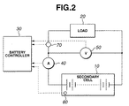
- Fig. 2 is a specific circuit block diagram of a battery controller and a secondary cell load drive system to which the input and output enabling power estimating apparatus according to the present invention is applicable.
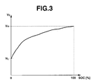
- Fig. 3 is a map representing a relationship between an open-circuit voltage and a charge rate (SOC).
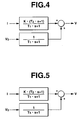
- Fig. 4 is a model view representing an equivalent circuit model of the secondary cell in the input and output enabling power estimating apparatus of the first preferred embodiment.
- Fig. 5 is a model view representing an equivalent circuit model of the secondary cell in the input and output enabling power estimating apparatus of the second preferred embodiment.
- Fig. 6 is a processing flowchart representing a calculation process in the case of the first preferred embodiment of the input and output enabling power estimating apparatus according to the present invention.
- Fig. 7 is a processing flowchart representing a calculation process in the case of the second preferred embodiment of the input and output enabling power estimating apparatus according to the present invention.
- Figs. 8A, 8B, 8C, 8D, 8E, 8F, 8G, 8H, 81 show integrally a timing chart representing a result of a simulation based on the first embodiment of the input and output enabling power estimating apparatus according to the present invention.
- Figs. 9A, 9B, 9C, 9D, 9E, 9F, 9G, 9H, 9I, 9J show integrally a timing chart representing a result of a simulation based on the second embodiment of the input and output enabling power estimating apparatus according to the present invention.
- Fig. 1 shows a functional block diagram of input and output enabling power estimating apparatus according to the present invention for explaining a general concept of each of first and second preferred embodiments which will be described later.
- a reference numeral 1 denotes a parameter ⁇ (k) estimating section that integrally estimates each parameter (the detailed description thereof will herein be omitted) in a cell model in which an open-circuit voltage Vo(k) is an offset term using measured voltage V and current I detected by current I(k) detecting section 5 and terminal voltage V(k) detecting section 6.
- a reference numeral 2 denotes an open-circuit voltage calculating section Vo(k). The open-circuit voltage Vo(k) is calculated on the basis of the measured voltage V and current I and each estimated parameter.
- a reference numeral 3 denotes an input enabling power estimating section which estimates a power which can be inputted to the secondary cell on the basis of parameter ⁇ (k) and open-circuit voltage Vo(k).
- a reference numeral 4 denotes an output enabling power estimating section that estimates the power which can be outputted from the secondary cell on the basis of parameter ⁇ (k) and open-circuit voltage Vo(k).
- a reference numeral 5 denotes a current I(k) detecting section that detects the current charged to or discharged from the secondary cell.
- a reference numeral 6 denotes a terminal voltage V(k) detecting section that detects a terminal voltage of the cell.
- Fig. 2 shows a block diagram representing a specific structure of a battery controller and a secondary cell load driving system to which the input and output enabling power estimating apparatus according to the present invention is applicable.
- the input and output enabling power estimating apparatus is mounted in a system in which a load such as a motor is driven and a regenerative power of the motor is used to charge the secondary cell.
- a reference numeral 10 denotes a secondary cell (or merely, a cell)
- a reference numeral 20 denotes a load of the motor or so on
- a reference numeral 30 denotes a battery controller (an electronic control unit) which functions to estimate the input and output enabling powers of cell 10.
- Battery controller 30 includes a microcomputer including a CPU (Central Processing Unit) that calculates a program, a ROM (Read Only Memory) that stores the program, a RAM (Random Access Memory) storing a result of calculations, and electronic circuits.
- a reference numeral 40 denotes a current meter that measures (detects) a current which is charged into and discharged from secondary cell 10.
- a reference numeral 50 denotes a voltage meter to detect a terminal voltage across secondary cell 10. These meters are connected to battery controller 30.
- the above-described battery controller 30 corresponds to parameter ⁇ (k) estimating section 1 of Fig. 1, open-circuit voltage Vo(k) calculating section 2, input enabling power estimating section 3, and output enabling power estimating section 4.
- current meter 40 corresponds to current I(k) detecting section 5 and voltage meter 50 corresponds to a terminal voltage V(k) detecting section 6, respectively.
- a reference numeral 60 shown in Fig. 2 denotes a temperature sensor to detect a cell temperature and a reference numeral 70 shown in Fig. 2 denotes a relay circuit (or simply a relay).
- Fig. 4 shows an equivalent circuit model of the secondary cell in the first embodiment.
- This equivalent circuit model corresponds to a case where denominators of right side first term and right side second term are the same as shown in equation (2).
- This equivalent circuit model is a reduction model (first order or fist degree) in which positive pole and negative pole are not especially separated) but enabled to represent a relatively accurate charge-and-discharge characteristic of the actual cell.
- a model input is current I [A] (Amperes) (positive value is charge and negative value is discharge) and model output is a terminal voltage V[V].
- Vo[V] denotes an open-circuit voltage (or called, an electromotive force or open voltage).
- K denotes an internal resistance
- T 1 and T 2 denote time constants
- Equation (3) K • ( T 2 • s + 1) T 1 • s + 1 • I + 1 T 1 • s + 1 • V 0
- the denominators of right side first term and right side second term can be represented by the same time constant T 1 as appreciated from equation (3).
- a value of an actually measurable current I and terminal voltage V for which a low pas filter and a band pass filter are processed is defined as in the following equation (8).
- a time constant p of equation (8) is a constant determining a response characteristic of G 1p (s).
- Equation (10) indicates a product-and-sum equation between measurable value and unknown parameters.
- Equation (12) Upon an assumption of equation (11), a parameter estimation algorithm to estimate an unknown parameter vector ⁇ is described in an equation (12). It is noted that parameter estimated values at a time point of k is assumed to be ⁇ (k).
- ⁇ 1 , ⁇ 3 , ⁇ U , y L denotes initial set values, 0 ⁇ ⁇ 1 ⁇ 1, 0 ⁇ ⁇ 3 ⁇ ⁇ .
- P(0) is a sufficiently large initial value and trace ⁇ P ⁇ means a trace of a matrix P. In this way, the derivation of the adaptive digital filter from the cell model has been explained.
- Fig. 6 shows an operational flowchart executing a microcomputer of battery controller 30.
- the routine shown in Fig. 6 is repeated for each constant period of time To.
- I(k) is the present value
- I(k-1) is the value one time before the present time of k.
- battery controller 30 measures current I(k) and terminal voltage V(k).
- battery controller 30 determines that terminal voltage V(k) is stored as terminal voltage initial value V _int .
- battery controller 30 performs a low pass filter (LPF) and a band pass filter (BPF) processing based on equation (13) for current I(k) and terminal voltage difference value ⁇ V(k) to calculate I 1 through I 3 and V 1 through V 3 .
- LPF low pass filter
- BPF band pass filter
- a response characteristic of low pass filter G 1p (s) is set to be slow so as to reduce observed noises.
- Time constant p in equation (13) is a constant to determine the response characteristic of G 1p (s) during the equation (13).
- back-up controller 30 substitutes T 1 , K • T 2 , and K from among parameter estimated value ⁇ (k) calculated at step S60A into the following equation (14) from among parameter estimated values ⁇ (k) calculated at step S60A into equation (14), I 1 , and I 2 , and V 1 , and V 2 calculated at equation (13).
- the open-circuit voltage initial value namely, a terminal voltage initial value V _ini is added to ⁇ Vc(k) calculated at step S70A to calculate open-circuit voltage estimated value Vo(k) using the following equation (15).
- V 0 (k) ⁇ V 0 (k) + V _ini
- battery controller 30 calculates an input enabling power estimated value P in and an output enabling power estimated value P out .
- equation (3) the detailed description of the calculation method of the input enabling power estimated value will be described below.
- equation (16) is resulted. This means that this means a quantitative cell model.
- minimum enabling voltage V min is substituted into V in equation (16)
- estimated value K from among the parameter estimated value ⁇ (k) calculated at step S60A is substituted into K
- circuit voltage estimated value Vo(k) calculated at step S80A is substituted into Vo, respectively, to calculate maximum input current I in_max.
- input enabling power estimated value Pin and output enabling power estimated value P out are calculated from equation (17).
- Maximum enabling voltage V max is a terminal voltage in a case where the cell is charged to a voltage immediately before the cell is the excessive charge.
- Minimum enabling voltage V min is a terminal voltage in a case where the cell is discharged to a value immediately before the cell is the excessive charge.
- V max and minimum enabling voltage V min are variables determined by the kind of cells and the cell temperature. For example, a relationship between the cell temperature and V max determined according to, for example, the experiments and a relationship between the cell temperature and V min can be stored as maps and a map reference can be used to calculate V max and V min .
- a step S110A numerical values required for the subsequent calculation are stored and the present calculation is ended. An operation of the first embodiment has been described above.
- equation (3) it becomes possible to apply the adaptive digital filter (well known estimating algorithm) such as the method of the least square. Consequently, it becomes possible to integrally estimate the parameters in equations (coefficients of poly-nominals (A(s) and B(s)).
- the estimated parameters are substituted into equation (2), the estimated value of open-circuit voltage Vo can easily be calculated.
- the adaptive digital filter can sequentially be estimated with a high accuracy. Since input enabling power P in and output enabling power P out are estimated using the estimated coefficient parameters and the open-circuit voltages Vo, the input and output enabling power P in and P out can be estimated, even if the input and output enabling powers are varied during the charge or discharge operation, its variation can accurately follow to estimate the input and output enabling powers.
- Figs. 8A through 8I show integrally results of simulations of the input and output enabling power estimations based on the first embodiment.
- Figs. 8A through 8I with a time of 400 seconds as a boundary, the cell parameters are changed in a stepwise manner from a high temperature corresponding value to a low temperature corresponding value. It is noted that, in this example of Figs. 8A through 8I, such as a lithium ion battery, the cell having a fast convergence of the open-circuit voltage is presumed. As appreciated from Figs. 8A through 8I, time constants T 1 , T 2 , and internal resistance K are considerably coincident with real values even if the cell parameter given when the simulations are carried out are varied in a stepwise manner. Hence, the open-circuit voltage estimated values are similarly coincident with the true values.
- Fig. 5 shows an equivalent circuit model of the secondary cell in the second embodiment.
- V B ( s ) A ( s ) • I + 1 C ( s ) • V o
- A(s), B(s), and C(s) denote a poly-nominal of s (n denotes an order number) and a 1 ⁇ 0, b 1 ⁇ 0, and c 1 ⁇ 0.
- the equivalent circuit model corresponds to a case where the denominators of the first term and the second term are different as described in equation (1).
- This equivalent circuit model is a reduction model (first degree or first order) in which a positive pole and a negative pole are not specially separated from each other but can relatively accurately indicate the charge-and-discharge characteristics of the actual cell.
- first degree or first order in which a positive pole and a negative pole are not specially separated from each other but can relatively accurately indicate the charge-and-discharge characteristics of the actual cell.
- a model input is current I [A] (positive value indicates the charge and negative value indicates the discharge) and a model output indicates terminal voltage V [V] and Vo[V] indicates open-circuit voltage (referred also to as an electromotive force or open (circuit) voltage).
- a symbol K denotes the internal resistance.
- T 1 through T 3 denotes time constants.
- This cell model can be expressed as in the following equation (18). It is noted that s denotes a Laplace transform operator. As a lead-acid battery cell ( or lead storage battery), the convergence of the open-circuit voltage is very slow cell, the relationship between T 1 « T 3 is present.
- the open-circuit voltage Vo can be written with the value of current I multiplied by a variable efficiency h considered as an integration value from a certain initial state.
- V 0 h s • I If equation (19) is substituted into equation (18), the following equation (20) is given. If arranged, the following equation (21) is given.
- equation (26) indicates a product-and-sum equation between measurable values and unknown parameters
- equation (26) is coincident with a standard form (equation (27)) of a general adaptive digital filter. It is noted that ⁇ T means a transposed vector in which a row and a column of a vector ⁇ are replaced with each other.
- ⁇ 1 , ⁇ 3 , ⁇ U , and ⁇ L are initial set values and 0 ⁇ ⁇ 1 ⁇ 1 and 0 ⁇ ⁇ 2 (k) ⁇ ⁇ .
- P ( 0 ) has a sufficiently large initial value and has a sufficiently small initial value which is not zero.
- trace ⁇ P ⁇ means a matrix P trace.
- Fig. 7 shows an operational flowchart carrying out a microcomputer of battery controller 30. The routine shown in Fig. 7 is executed whenever a constant period of time To has passed.
- I(k) means the present value and I(k-1) denotes one previous value as described in the first embodiemnt.
- I(k) means the present value
- I(k-1) denotes one previous value as described in the first embodiemnt.
- steps S10B through S40B are the same as those of steps S10A through S40A described in Fig. 6. Hence, the explanation thereof will herein be omitted.
- the low pass filtering and the band pass filtering are carried for current I(k) and terminal voltage difference value ⁇ V(k) on the basis of the following equation (29) to calculate Io(k) through I 3 (k) and V 1 (k) through V 3 (k). It is noted that, in this case, in order to improve an estimation accuracy of parameter estimation algorithm of equation (28), the response characteristic of low pass filter G 1 (s) is set to be slow so as to reduce the observed noises.
- controller 30 substitutes I o (k) through I 3 (k) and V 1 (k) through V 3 (k) into equation (28).
- the calculation in accordance with equation (28) which is the parameter estimation algorithm is, then, calculated to determine parameter estimated value ⁇ (k). It is noted that y(k), ⁇ T (k), and ⁇ (k) are given in the following equation (30).
- the filtering processes of low pass filter and band pass filter are carried out on the basis of current I(k) and terminal voltage difference value ⁇ V(k) on the basis of an equation (34) to calculate I 4 (k) through I 6 (k) and V 4 (k) through V 6 (k).
- Equation (33) is a deformation from equation (18) to calculate ⁇ Vo which is used in place of the open-circuit voltage Vo. Since the variation in open-circuit voltage Vo is moderate, ⁇ Vo can be substituted.
- the derivation at step S70B is the variation quantity ⁇ Vo(k) of the open-circuit voltage Vo(k) from a time at which the estimation calculation is started. Therefore, the initial value is added at a later step S90B. It is noted that, at the derivation of equation (33), K in the equation (32) and e of the equation (33) are strictly different from each other.
- the open-circuit voltage initial value namely, terminal voltage initial value V _ini is added to each of Vo(k) and Vo'(k) calculated at step S70B. That is to say, open-circuit voltage estimated value Vo(k) is calculated using the equation (36) and apparent open-circuit voltage estimated valu Vo'(k) is calculated using the following equation (37). It is noted that estimated value Vo' is not the estimated value Vo' of open-circuit voltage Vo itself but the apparent open-circuit voltage estimated value appearing on the terminal voltage.
- battery controller 30 determines whether estimated value Vo(k) is equal to or larger than open-circuit voltage estimated value Vo'(k).
- This determination at step S100B functions to search either one of which is nearer to either maximum enabling voltage V max or minimum enabling voltage V min .
- maximum enabling voltage V max or minimum enabling voltage V min is a variable determined by the kinds of cells and temperature in the cell.
- the calculation method is the well known method so that they can be determined using the well known technique as described in the first embodiment.
- step S100B if Vo'(k) ⁇ Vo(k), the routine goes to a step S110B. If Vo'(k) ⁇ Vo(k), the routine goes to a step S120B.
- battery controller 30 calculates input enabling power estimated value P in and output enabling power estimated value Pout.
- the cell model is expressed in equation (38) in a case where a transient characteristic is ignored and this means a quantitative cell model.
- To calculate input enabling power estimated value Pin the current value to reach to maximum enabling voltage V max is needed.
- maximum input current I in_max is calculated using equation (38) in which the transient characteristic is ignored. That is to say, at step S110B, since Vo'(k) ⁇ Vo(k), Vo'(k) is nearer to maximum enabling power V max and Vo(k) is nearer to minimum enabling voltage V min .
- V max K • I + V o
- V max e • I in_max + V 0 '
- V min e • I out_max + V o
- step 120B battery controller 30 calculates input enabling power estimated value P in and output enabling power estimated value P out. Since step S120B is the case where Vo'(k) ⁇ Vo(k), Vo(k) is nearer to maximum enabling voltage V max and Vo'(k) is nearer to minimum enabling voltage V min . Hence, in order to calculate input enabling power estimated value P in , maximum enabling voltage V max , estimated value e from among parameter estimated value ⁇ (k) calculated at step S60B using an equation (42) obtained by substituting Vo(k) calculated at step S80B into equation (38). Thus, an equation (43) is given. Maximum output enabling current I out_max is calculated using equation (43).
- the relationship from among current I of the secondary cell, terminal voltage V, and open-circuit voltage Vo is constituted to be approximated by means of the transfer function such as equation (1) (specifically, equation (18)), it is possible to apply to the adaptive digital filter of the method of least squares. Consequently, it becomes possible to integrally estimate the parameters at one time (coefficients of poly-nominals of A(s), B(s), and C(s)). Since the estimated parameters are substituted into equation (1), the estimated value of open-circuit voltage Vo can easily be calculated.
- Fig. 9A through 9J integrally show a simulation result of the input output enabling power estimations based on the second embodiment.
- the cell parameters are varied from a low temperature corresponding value to a high temperature corresponding value in a stepwise manner.
- T 1 ⁇ T 3 is set. This is because, the cell having the very slow convergence characteristic of open-circuit voltage Vo like the lead-acid battery is assumed and set.
- parameter estimated values a through e that the adaptive digital filter outputs are coincident with their real values even if the cell parameter given when the simulation is carried out is varied in the stepwise manner (substantially at a right angle).
- the open-circuit voltage estimated value are coincident with the real values.
- input enabling power P in is estimated using the estimated coefficient parameter, open-circuit voltage Vo, and maximum enabling voltage V max .
- the output enabling power estimated value can be coincident with the real value. It is noted that an attention needs to be paid to develop the first-order lag of time constant T 3 in an apparent appearance on the real value of the open-circuit voltage and the terminal voltage (refer to right side second term of equation (18) of the cell model).
- a characteristic of reference indicates a value calculated using the open-circuit voltage estimated value.
- the input enabling power estimated value (dot-and-dash line) calculated using the open-circuit voltage estimated value is larger than the real value of the input enabling power. This is caused by the fact that the apparent open-circuit voltage is larger than the real value of the open-circuit voltage Vo and is nearer to maximum enabling voltage V max .
- the input enabling power estimated value (solid line) is calculated using apparent open-circuit voltage Vo/C(s) nearer to maximum enabling power estimated value V max (solid line).
- Vo/C(s) apparent open-circuit voltage
- V max apparent open-circuit voltage
- the characteristic described as the reference indicates a value calculated using the apparent open-circuit voltage estimated value.
- the output enabling power estimated value (a dot-and-dash line) calculated using the apparent open-circuit voltage estimated value is larger than the real value of the output enabling power. This is caused by the fact that the open-circuit voltage estimated value is smaller than the apparent open-circuit voltage and is nearer to minimum enabling voltage V min .
- this output enabling power estimated value breaks through minimum enabling voltage V min so that there is a possibility that the cell is deteriorated due to an over-discharge.
- the apparent open-circuit voltage Vo/C(s) is calculated from the estimated coefficient parameters and open circuit enabling voltage V min .
- the estimated coefficient parameters, and minimum enabling voltage V min output enabling power P out is estimated.
- the output enabling power estimated value (solid line) is calculated using the open-circuit voltage Vo which is nearer to minimum enabling power V min .
- the estimated value of the output enabling power is sufficiently coincident with the real value and there is no possibility that the output enabling power estimated value breaks through minimum enabling voltage V min of the cell.
- the relay described at steps S20A and S20B shown in Figs. 6 and 7 corresponds to relay 70 shown in Fig. 2.
Landscapes
- Engineering & Computer Science (AREA)
- Power Engineering (AREA)
- Transportation (AREA)
- Mechanical Engineering (AREA)
- Life Sciences & Earth Sciences (AREA)
- Sustainable Development (AREA)
- Sustainable Energy (AREA)
- Physics & Mathematics (AREA)
- General Physics & Mathematics (AREA)
- Secondary Cells (AREA)
- Tests Of Electric Status Of Batteries (AREA)
- Measurement Of Current Or Voltage (AREA)
Applications Claiming Priority (2)
| Application Number | Priority Date | Filing Date | Title |
|---|---|---|---|
| JP2003054035 | 2003-02-28 | ||
| JP2003054035A JP3714333B2 (ja) | 2003-02-28 | 2003-02-28 | 二次電池の入出力可能電力推定装置 |
Publications (3)
| Publication Number | Publication Date |
|---|---|
| EP1460441A2 true EP1460441A2 (de) | 2004-09-22 |
| EP1460441A3 EP1460441A3 (de) | 2005-02-09 |
| EP1460441B1 EP1460441B1 (de) | 2007-12-19 |
Family
ID=32821134
Family Applications (1)
| Application Number | Title | Priority Date | Filing Date |
|---|---|---|---|
| EP04002570A Expired - Lifetime EP1460441B1 (de) | 2003-02-28 | 2004-02-05 | Gerät und Verfahren zur Schätzung von der möglichen Eingangs- und Ausgangsleistung einer Sekundärbatterie |
Country Status (5)
| Country | Link |
|---|---|
| US (1) | US7009402B2 (de) |
| EP (1) | EP1460441B1 (de) |
| JP (1) | JP3714333B2 (de) |
| CN (1) | CN1312804C (de) |
| DE (1) | DE602004010733T2 (de) |
Cited By (5)
| Publication number | Priority date | Publication date | Assignee | Title |
|---|---|---|---|---|
| EP2320242A2 (de) * | 2008-08-08 | 2011-05-11 | LG Chem, Ltd. | Vorrichtung und verfahren für zellausgleich anhand des spannungsvariationsverhaltens einer batteriezelle |
| US8446127B2 (en) | 2005-08-03 | 2013-05-21 | California Institute Of Technology | Methods for thermodynamic evaluation of battery state of health |
| US9065292B2 (en) | 2010-08-23 | 2015-06-23 | California Institute Of Technology | Methods and systems for charging electrochemical cells |
| US9599584B2 (en) | 2012-04-27 | 2017-03-21 | California Institute Of Technology | Imbedded chip for battery applications |
| US10556510B2 (en) | 2012-04-27 | 2020-02-11 | California Institute Of Technology | Accurate assessment of the state of charge of electrochemical cells |
Families Citing this family (30)
| Publication number | Priority date | Publication date | Assignee | Title |
|---|---|---|---|---|
| JP4547908B2 (ja) * | 2003-12-25 | 2010-09-22 | 日産自動車株式会社 | 二次電池の入出力可能電力推定装置 |
| US7486079B2 (en) * | 2004-06-11 | 2009-02-03 | Nissan Motor Co., Ltd. | Available input-output power estimating device for secondary battery |
| JP4910300B2 (ja) * | 2005-04-08 | 2012-04-04 | 日産自動車株式会社 | 二次電池の満充電容量推定装置 |
| JP4830382B2 (ja) * | 2005-07-19 | 2011-12-07 | 日産自動車株式会社 | 二次電池の充電率推定装置 |
| US7595611B2 (en) * | 2005-08-03 | 2009-09-29 | California Institute Of Technology | Electrochemical thermodynamic measurement system |
| JP4788307B2 (ja) * | 2005-11-17 | 2011-10-05 | 日産自動車株式会社 | 二次電池の入出力可能電力推定装置 |
| JP4692246B2 (ja) | 2005-11-29 | 2011-06-01 | 日産自動車株式会社 | 二次電池の入出力可能電力推定装置 |
| DE102007032178B3 (de) * | 2007-07-10 | 2008-12-11 | Continental Automotive Gmbh | Kraftfahrzeug-Kontrollvorrichtung und zugehöriges Verfahren zur Regelung des elektrischen Stroms eines Aktuators |
| US7830119B2 (en) * | 2007-08-29 | 2010-11-09 | Gm Global Technology Operations, Inc. | Adaptive battery estimator and method |
| JPWO2009063923A1 (ja) * | 2007-11-13 | 2011-03-31 | 日本電気株式会社 | 電気機器 |
| KR20090077657A (ko) * | 2008-01-11 | 2009-07-15 | 에스케이에너지 주식회사 | 배터리 관리 시스템에서 배터리의 soc 측정 방법 및 장치 |
| JP4744622B2 (ja) * | 2009-07-01 | 2011-08-10 | トヨタ自動車株式会社 | 車両の制御装置 |
| JP5691592B2 (ja) | 2010-02-18 | 2015-04-01 | 日産自動車株式会社 | 電池状態推定装置 |
| US8319479B2 (en) * | 2010-03-23 | 2012-11-27 | Ememory Technology Inc. | Method of estimating battery recharge time and related device |
| TWI397240B (zh) * | 2010-05-03 | 2013-05-21 | Ememory Technology Inc | 智慧型電池裝置、對智慧型電池裝置的電池組充電的方法及智慧型電池裝置中產生近似於電池平均充滿時間的方法 |
| TWI499886B (zh) * | 2010-07-15 | 2015-09-11 | Univ Nat Taiwan | 估算電路的最大功率點功率的方法 |
| JP5842421B2 (ja) * | 2010-07-20 | 2016-01-13 | 日産自動車株式会社 | 電池状態推定装置 |
| US9354277B2 (en) * | 2010-10-29 | 2016-05-31 | Gm Global Technology Operatins Llc | Apparatus of SOC estimation during plug-in charge mode |
| JP5318128B2 (ja) * | 2011-01-18 | 2013-10-16 | カルソニックカンセイ株式会社 | バッテリの充電率推定装置 |
| US20140340045A1 (en) * | 2012-01-26 | 2014-11-20 | Calsonic Kansei Corporation | Apparatus for battery state estimation |
| JP5319854B1 (ja) * | 2012-02-22 | 2013-10-16 | カルソニックカンセイ株式会社 | パラメータ推定装置 |
| JP5900160B2 (ja) * | 2012-05-28 | 2016-04-06 | ソニー株式会社 | 二次電池の相対残容量推定方法、相対残容量推定装置、電池パック、電子機器及び電動車両 |
| JP6119402B2 (ja) * | 2012-05-29 | 2017-04-26 | 株式会社Gsユアサ | 内部抵抗推定装置及び内部抵抗推定方法 |
| CN103558554A (zh) * | 2013-10-15 | 2014-02-05 | 广东电网公司电力科学研究院 | 一种新能源汽车动力电池soh在线估算的方法 |
| JP5888315B2 (ja) * | 2013-12-18 | 2016-03-22 | トヨタ自動車株式会社 | 蓄電システム |
| CN104035037A (zh) * | 2014-05-12 | 2014-09-10 | 广东电网公司电力科学研究院 | 一种新能源汽车动力电池soh在线估算的方法 |
| US20160006275A1 (en) * | 2014-07-01 | 2016-01-07 | Ford Global Technologies, Llc | System and method for battery open circuit voltage estimation |
| CN104834803B (zh) * | 2014-09-29 | 2018-01-19 | 北汽福田汽车股份有限公司 | 电池最大允许功率计算方法及装置 |
| JP6401668B2 (ja) * | 2015-06-29 | 2018-10-10 | Kyb株式会社 | ハイブリッド建設機械の制御システム及び制御方法 |
| US11498446B2 (en) * | 2020-01-06 | 2022-11-15 | Ford Global Technologies, Llc | Plug-in charge current management for battery model-based online learning |
Citations (2)
| Publication number | Priority date | Publication date | Assignee | Title |
|---|---|---|---|---|
| JP2000030748A (ja) * | 1998-07-14 | 2000-01-28 | Nissan Motor Co Ltd | 電池の入出力演算装置 |
| JP2002006010A (ja) * | 2000-06-21 | 2002-01-09 | Nissan Motor Co Ltd | 電気自動車用電池の最大充放電電力演算装置 |
Family Cites Families (10)
| Publication number | Priority date | Publication date | Assignee | Title |
|---|---|---|---|---|
| US695800A (en) * | 1901-11-14 | 1902-03-18 | John Dellinger | Collapsible match-box. |
| SU853715A1 (ru) * | 1979-07-27 | 1981-08-07 | Предприятие П/Я В-2572 | Способ определени работоспособностиНиКЕль-КАдМиЕВОй АККуМул ТОРНОйбАТАРЕи |
| JP3191976B2 (ja) * | 1992-02-26 | 2001-07-23 | 株式会社ユアサコーポレーション | 電動車両用蓄電池の残存容量推定法 |
| JP3121732B2 (ja) * | 1994-11-04 | 2001-01-09 | 三菱電機株式会社 | 二次電池のパラメータ測定方法ならびにそれを用いた二次電池の充放電制御方法および寿命予測方法、ならびに、二次電池の充放電制御装置およびそれを用いた電力貯蔵装置 |
| JP3503313B2 (ja) | 1995-12-20 | 2004-03-02 | 日産自動車株式会社 | バッテリパワー演算装置 |
| ES2197638T3 (es) * | 1998-05-28 | 2004-01-01 | Toyota Jidosha Kabushiki Kaisha | Medios para estimar el estado de carga de una bateria y procedimiento para estimar el estado de degradacion de una bateria. |
| JP2000199679A (ja) * | 1998-12-28 | 2000-07-18 | Sanyo Electric Co Ltd | プレハブ低温庫 |
| JP3869676B2 (ja) * | 2000-12-08 | 2007-01-17 | 矢崎総業株式会社 | 車両用バッテリの開回路電圧推定方法及び装置 |
| JP2002365961A (ja) * | 2001-06-07 | 2002-12-20 | Ricoh Co Ltd | 画像形成装置 |
| JP3747826B2 (ja) | 2001-09-05 | 2006-02-22 | 日産自動車株式会社 | 二次電池の充電率推定装置 |
-
2003
- 2003-02-28 JP JP2003054035A patent/JP3714333B2/ja not_active Expired - Fee Related
-
2004
- 2004-02-05 EP EP04002570A patent/EP1460441B1/de not_active Expired - Lifetime
- 2004-02-05 DE DE602004010733T patent/DE602004010733T2/de not_active Expired - Lifetime
- 2004-02-10 US US10/774,574 patent/US7009402B2/en not_active Expired - Lifetime
- 2004-02-27 CN CNB2004100072805A patent/CN1312804C/zh not_active Expired - Fee Related
Patent Citations (2)
| Publication number | Priority date | Publication date | Assignee | Title |
|---|---|---|---|---|
| JP2000030748A (ja) * | 1998-07-14 | 2000-01-28 | Nissan Motor Co Ltd | 電池の入出力演算装置 |
| JP2002006010A (ja) * | 2000-06-21 | 2002-01-09 | Nissan Motor Co Ltd | 電気自動車用電池の最大充放電電力演算装置 |
Non-Patent Citations (3)
| Title |
|---|
| DATABASE WPI Section EI, Week 198221 Derwent Publications Ltd., London, GB; Class X16, AN 1982-G2881E XP002309520 & SU 853 715 B (PINIGIN N YA) 17 August 1981 (1981-08-17) * |
| PATENT ABSTRACTS OF JAPAN vol. 2000, no. 04, 31 August 2000 (2000-08-31) & JP 2000 030748 A (NISSAN MOTOR CO LTD), 28 January 2000 (2000-01-28) * |
| PATENT ABSTRACTS OF JAPAN vol. 2002, no. 05, 3 May 2002 (2002-05-03) & JP 2002 006010 A (NISSAN MOTOR CO LTD), 9 January 2002 (2002-01-09) * |
Cited By (7)
| Publication number | Priority date | Publication date | Assignee | Title |
|---|---|---|---|---|
| US8446127B2 (en) | 2005-08-03 | 2013-05-21 | California Institute Of Technology | Methods for thermodynamic evaluation of battery state of health |
| US8901892B2 (en) | 2005-08-03 | 2014-12-02 | California Institute Of Technology | Methods and systems for thermodynamic evaluation of battery state of health |
| EP2320242A2 (de) * | 2008-08-08 | 2011-05-11 | LG Chem, Ltd. | Vorrichtung und verfahren für zellausgleich anhand des spannungsvariationsverhaltens einer batteriezelle |
| EP2320242A4 (de) * | 2008-08-08 | 2013-11-13 | Lg Chemical Ltd | Vorrichtung und verfahren für zellausgleich anhand des spannungsvariationsverhaltens einer batteriezelle |
| US9065292B2 (en) | 2010-08-23 | 2015-06-23 | California Institute Of Technology | Methods and systems for charging electrochemical cells |
| US9599584B2 (en) | 2012-04-27 | 2017-03-21 | California Institute Of Technology | Imbedded chip for battery applications |
| US10556510B2 (en) | 2012-04-27 | 2020-02-11 | California Institute Of Technology | Accurate assessment of the state of charge of electrochemical cells |
Also Published As
| Publication number | Publication date |
|---|---|
| DE602004010733T2 (de) | 2008-04-30 |
| EP1460441B1 (de) | 2007-12-19 |
| JP3714333B2 (ja) | 2005-11-09 |
| CN1525592A (zh) | 2004-09-01 |
| DE602004010733D1 (de) | 2008-01-31 |
| CN1312804C (zh) | 2007-04-25 |
| US7009402B2 (en) | 2006-03-07 |
| JP2004264126A (ja) | 2004-09-24 |
| US20040169495A1 (en) | 2004-09-02 |
| EP1460441A3 (de) | 2005-02-09 |
Similar Documents
| Publication | Publication Date | Title |
|---|---|---|
| EP1460441B1 (de) | Gerät und Verfahren zur Schätzung von der möglichen Eingangs- und Ausgangsleistung einer Sekundärbatterie | |
| Yang et al. | State-of-health estimation for the lithium-ion battery based on support vector regression | |
| US7564221B2 (en) | Device and method for estimating the inputtable/outputtable power of a secondary battery | |
| EP3876334A1 (de) | Batteriemanagementvorrichtung und -verfahren | |
| Li et al. | A multi-model probability SOC fusion estimation approach using an improved adaptive unscented Kalman filter technique | |
| US7197487B2 (en) | Apparatus and method for estimating battery state of charge | |
| Codeca et al. | On battery state of charge estimation: A new mixed algorithm | |
| Chen et al. | Adaptive gain sliding mode observer for state of charge estimation based on combined battery equivalent circuit model | |
| US10175303B2 (en) | Battery parameter estimation device and parameter estimation method | |
| JP4623448B2 (ja) | 二次電池の残存容量演算方法 | |
| US6534954B1 (en) | Method and apparatus for a battery state of charge estimator | |
| CN104142477B (zh) | 固态浓度模型结合经验等效电路模型的蓄电池状态估计器 | |
| US7358704B2 (en) | Critical state estimation system and method for secondary cells | |
| US7098625B2 (en) | Apparatus and method for estimating charge rate of secondary cell | |
| US20060111870A1 (en) | Method and system for joint battery state and parameter estimation | |
| EP3940405B1 (de) | Verfahren zur schätzung des gesundheitszustands einer batterie | |
| JP4609882B2 (ja) | 車両用蓄電装置の内部状態検出方式 | |
| CN101395489A (zh) | 用于确定估计的电池组状态向量和估计的电池组参数向量的系统和方法 | |
| CN104931784A (zh) | 基于频率的电池模型参数估计 | |
| US20050275407A1 (en) | Available input-output power estimating device for secondary battery | |
| JP2015524048A (ja) | バッテリの充電状態の推定 | |
| CN110231567A (zh) | 一种电动汽车soc估算算法 | |
| CN106126783A (zh) | 一种锂离子电池变时间尺度模型参数估计方法 | |
| US20230236250A1 (en) | Battery voltage prediction apparatus and method | |
| US10908219B2 (en) | Battery management system with mixed electrode |
Legal Events
| Date | Code | Title | Description |
|---|---|---|---|
| PUAI | Public reference made under article 153(3) epc to a published international application that has entered the european phase |
Free format text: ORIGINAL CODE: 0009012 |
|
| 17P | Request for examination filed |
Effective date: 20040205 |
|
| AK | Designated contracting states |
Kind code of ref document: A2 Designated state(s): AT BE BG CH CY CZ DE DK EE ES FI FR GB GR HU IE IT LI LU MC NL PT RO SE SI SK TR |
|
| AX | Request for extension of the european patent |
Extension state: AL LT LV MK |
|
| PUAL | Search report despatched |
Free format text: ORIGINAL CODE: 0009013 |
|
| AK | Designated contracting states |
Kind code of ref document: A3 Designated state(s): AT BE BG CH CY CZ DE DK EE ES FI FR GB GR HU IE IT LI LU MC NL PT RO SE SI SK TR |
|
| AX | Request for extension of the european patent |
Extension state: AL LT LV MK |
|
| AKX | Designation fees paid |
Designated state(s): DE FR GB |
|
| GRAP | Despatch of communication of intention to grant a patent |
Free format text: ORIGINAL CODE: EPIDOSNIGR1 |
|
| GRAS | Grant fee paid |
Free format text: ORIGINAL CODE: EPIDOSNIGR3 |
|
| GRAA | (expected) grant |
Free format text: ORIGINAL CODE: 0009210 |
|
| AK | Designated contracting states |
Kind code of ref document: B1 Designated state(s): DE FR GB |
|
| REG | Reference to a national code |
Ref country code: GB Ref legal event code: FG4D |
|
| REF | Corresponds to: |
Ref document number: 602004010733 Country of ref document: DE Date of ref document: 20080131 Kind code of ref document: P |
|
| ET | Fr: translation filed | ||
| PLBE | No opposition filed within time limit |
Free format text: ORIGINAL CODE: 0009261 |
|
| STAA | Information on the status of an ep patent application or granted ep patent |
Free format text: STATUS: NO OPPOSITION FILED WITHIN TIME LIMIT |
|
| 26N | No opposition filed |
Effective date: 20080922 |
|
| REG | Reference to a national code |
Ref country code: FR Ref legal event code: PLFP Year of fee payment: 13 |
|
| REG | Reference to a national code |
Ref country code: FR Ref legal event code: PLFP Year of fee payment: 14 |
|
| REG | Reference to a national code |
Ref country code: FR Ref legal event code: PLFP Year of fee payment: 15 |
|
| PGFP | Annual fee paid to national office [announced via postgrant information from national office to epo] |
Ref country code: FR Payment date: 20210113 Year of fee payment: 18 |
|
| PGFP | Annual fee paid to national office [announced via postgrant information from national office to epo] |
Ref country code: GB Payment date: 20210127 Year of fee payment: 18 Ref country code: DE Payment date: 20210126 Year of fee payment: 18 |
|
| REG | Reference to a national code |
Ref country code: DE Ref legal event code: R119 Ref document number: 602004010733 Country of ref document: DE |
|
| GBPC | Gb: european patent ceased through non-payment of renewal fee |
Effective date: 20220205 |
|
| PG25 | Lapsed in a contracting state [announced via postgrant information from national office to epo] |
Ref country code: FR Free format text: LAPSE BECAUSE OF NON-PAYMENT OF DUE FEES Effective date: 20220228 |
|
| PG25 | Lapsed in a contracting state [announced via postgrant information from national office to epo] |
Ref country code: GB Free format text: LAPSE BECAUSE OF NON-PAYMENT OF DUE FEES Effective date: 20220205 Ref country code: DE Free format text: LAPSE BECAUSE OF NON-PAYMENT OF DUE FEES Effective date: 20220901 |