EP1460432B1 - Sample dispensing apparatus and automatic analyzer including the same - Google Patents
Sample dispensing apparatus and automatic analyzer including the same Download PDFInfo
- Publication number
- EP1460432B1 EP1460432B1 EP04002367.3A EP04002367A EP1460432B1 EP 1460432 B1 EP1460432 B1 EP 1460432B1 EP 04002367 A EP04002367 A EP 04002367A EP 1460432 B1 EP1460432 B1 EP 1460432B1
- Authority
- EP
- European Patent Office
- Prior art keywords
- sample
- probes
- dispensing
- probe
- container
- Prior art date
- Legal status (The legal status is an assumption and is not a legal conclusion. Google has not performed a legal analysis and makes no representation as to the accuracy of the status listed.)
- Expired - Lifetime
Links
Images

Classifications
-
- G—PHYSICS
- G01—MEASURING; TESTING
- G01N—INVESTIGATING OR ANALYSING MATERIALS BY DETERMINING THEIR CHEMICAL OR PHYSICAL PROPERTIES
- G01N35/00—Automatic analysis not limited to methods or materials provided for in any single one of groups G01N1/00 - G01N33/00; Handling materials therefor
- G01N35/00584—Control arrangements for automatic analysers
- G01N35/0092—Scheduling
-
- G—PHYSICS
- G01—MEASURING; TESTING
- G01N—INVESTIGATING OR ANALYSING MATERIALS BY DETERMINING THEIR CHEMICAL OR PHYSICAL PROPERTIES
- G01N35/00—Automatic analysis not limited to methods or materials provided for in any single one of groups G01N1/00 - G01N33/00; Handling materials therefor
- G01N35/10—Devices for transferring samples or any liquids to, in, or from, the analysis apparatus, e.g. suction devices, injection devices
- G01N35/1095—Devices for transferring samples or any liquids to, in, or from, the analysis apparatus, e.g. suction devices, injection devices for supplying the samples to flow-through analysers
-
- B—PERFORMING OPERATIONS; TRANSPORTING
- B01—PHYSICAL OR CHEMICAL PROCESSES OR APPARATUS IN GENERAL
- B01F—MIXING, e.g. DISSOLVING, EMULSIFYING OR DISPERSING
- B01F31/00—Mixers with shaking, oscillating, or vibrating mechanisms
- B01F31/44—Mixers with shaking, oscillating, or vibrating mechanisms with stirrers performing an oscillatory, vibratory or shaking movement
-
- G—PHYSICS
- G01—MEASURING; TESTING
- G01N—INVESTIGATING OR ANALYSING MATERIALS BY DETERMINING THEIR CHEMICAL OR PHYSICAL PROPERTIES
- G01N35/00—Automatic analysis not limited to methods or materials provided for in any single one of groups G01N1/00 - G01N33/00; Handling materials therefor
- G01N35/02—Automatic analysis not limited to methods or materials provided for in any single one of groups G01N1/00 - G01N33/00; Handling materials therefor using a plurality of sample containers moved by a conveyor system past one or more treatment or analysis stations
- G01N35/021—Automatic analysis not limited to methods or materials provided for in any single one of groups G01N1/00 - G01N33/00; Handling materials therefor using a plurality of sample containers moved by a conveyor system past one or more treatment or analysis stations having a flexible chain, e.g. "cartridge belt", conveyor for reaction cells or cuvettes
-
- G—PHYSICS
- G01—MEASURING; TESTING
- G01N—INVESTIGATING OR ANALYSING MATERIALS BY DETERMINING THEIR CHEMICAL OR PHYSICAL PROPERTIES
- G01N35/00—Automatic analysis not limited to methods or materials provided for in any single one of groups G01N1/00 - G01N33/00; Handling materials therefor
- G01N35/02—Automatic analysis not limited to methods or materials provided for in any single one of groups G01N1/00 - G01N33/00; Handling materials therefor using a plurality of sample containers moved by a conveyor system past one or more treatment or analysis stations
- G01N35/025—Automatic analysis not limited to methods or materials provided for in any single one of groups G01N1/00 - G01N33/00; Handling materials therefor using a plurality of sample containers moved by a conveyor system past one or more treatment or analysis stations having a carousel or turntable for reaction cells or cuvettes
-
- G—PHYSICS
- G01—MEASURING; TESTING
- G01N—INVESTIGATING OR ANALYSING MATERIALS BY DETERMINING THEIR CHEMICAL OR PHYSICAL PROPERTIES
- G01N35/00—Automatic analysis not limited to methods or materials provided for in any single one of groups G01N1/00 - G01N33/00; Handling materials therefor
- G01N35/10—Devices for transferring samples or any liquids to, in, or from, the analysis apparatus, e.g. suction devices, injection devices
- G01N35/1002—Reagent dispensers
-
- G—PHYSICS
- G01—MEASURING; TESTING
- G01N—INVESTIGATING OR ANALYSING MATERIALS BY DETERMINING THEIR CHEMICAL OR PHYSICAL PROPERTIES
- G01N35/00—Automatic analysis not limited to methods or materials provided for in any single one of groups G01N1/00 - G01N33/00; Handling materials therefor
- G01N35/10—Devices for transferring samples or any liquids to, in, or from, the analysis apparatus, e.g. suction devices, injection devices
- G01N35/1004—Cleaning sample transfer devices
-
- G—PHYSICS
- G01—MEASURING; TESTING
- G01N—INVESTIGATING OR ANALYSING MATERIALS BY DETERMINING THEIR CHEMICAL OR PHYSICAL PROPERTIES
- G01N35/00—Automatic analysis not limited to methods or materials provided for in any single one of groups G01N1/00 - G01N33/00; Handling materials therefor
- G01N35/10—Devices for transferring samples or any liquids to, in, or from, the analysis apparatus, e.g. suction devices, injection devices
- G01N35/1009—Characterised by arrangements for controlling the aspiration or dispense of liquids
- G01N35/1011—Control of the position or alignment of the transfer device
-
- G—PHYSICS
- G01—MEASURING; TESTING
- G01N—INVESTIGATING OR ANALYSING MATERIALS BY DETERMINING THEIR CHEMICAL OR PHYSICAL PROPERTIES
- G01N35/00—Automatic analysis not limited to methods or materials provided for in any single one of groups G01N1/00 - G01N33/00; Handling materials therefor
- G01N35/10—Devices for transferring samples or any liquids to, in, or from, the analysis apparatus, e.g. suction devices, injection devices
- G01N35/1009—Characterised by arrangements for controlling the aspiration or dispense of liquids
- G01N35/1016—Control of the volume dispensed or introduced
-
- G—PHYSICS
- G01—MEASURING; TESTING
- G01N—INVESTIGATING OR ANALYSING MATERIALS BY DETERMINING THEIR CHEMICAL OR PHYSICAL PROPERTIES
- G01N35/00—Automatic analysis not limited to methods or materials provided for in any single one of groups G01N1/00 - G01N33/00; Handling materials therefor
- G01N35/10—Devices for transferring samples or any liquids to, in, or from, the analysis apparatus, e.g. suction devices, injection devices
- G01N35/1065—Multiple transfer devices
-
- G—PHYSICS
- G01—MEASURING; TESTING
- G01N—INVESTIGATING OR ANALYSING MATERIALS BY DETERMINING THEIR CHEMICAL OR PHYSICAL PROPERTIES
- G01N35/00—Automatic analysis not limited to methods or materials provided for in any single one of groups G01N1/00 - G01N33/00; Handling materials therefor
- G01N35/10—Devices for transferring samples or any liquids to, in, or from, the analysis apparatus, e.g. suction devices, injection devices
- G01N35/1081—Devices for transferring samples or any liquids to, in, or from, the analysis apparatus, e.g. suction devices, injection devices characterised by the means for relatively moving the transfer device and the containers in an horizontal plane
- G01N35/109—Devices for transferring samples or any liquids to, in, or from, the analysis apparatus, e.g. suction devices, injection devices characterised by the means for relatively moving the transfer device and the containers in an horizontal plane with two horizontal degrees of freedom
-
- G—PHYSICS
- G01—MEASURING; TESTING
- G01N—INVESTIGATING OR ANALYSING MATERIALS BY DETERMINING THEIR CHEMICAL OR PHYSICAL PROPERTIES
- G01N35/00—Automatic analysis not limited to methods or materials provided for in any single one of groups G01N1/00 - G01N33/00; Handling materials therefor
- G01N2035/00178—Special arrangements of analysers
- G01N2035/00237—Handling microquantities of analyte, e.g. microvalves, capillary networks
-
- G—PHYSICS
- G01—MEASURING; TESTING
- G01N—INVESTIGATING OR ANALYSING MATERIALS BY DETERMINING THEIR CHEMICAL OR PHYSICAL PROPERTIES
- G01N35/00—Automatic analysis not limited to methods or materials provided for in any single one of groups G01N1/00 - G01N33/00; Handling materials therefor
- G01N35/02—Automatic analysis not limited to methods or materials provided for in any single one of groups G01N1/00 - G01N33/00; Handling materials therefor using a plurality of sample containers moved by a conveyor system past one or more treatment or analysis stations
- G01N35/04—Details of the conveyor system
- G01N2035/0401—Sample carriers, cuvettes or reaction vessels
- G01N2035/0406—Individual bottles or tubes
-
- G—PHYSICS
- G01—MEASURING; TESTING
- G01N—INVESTIGATING OR ANALYSING MATERIALS BY DETERMINING THEIR CHEMICAL OR PHYSICAL PROPERTIES
- G01N35/00—Automatic analysis not limited to methods or materials provided for in any single one of groups G01N1/00 - G01N33/00; Handling materials therefor
- G01N35/10—Devices for transferring samples or any liquids to, in, or from, the analysis apparatus, e.g. suction devices, injection devices
- G01N35/1009—Characterised by arrangements for controlling the aspiration or dispense of liquids
- G01N35/1016—Control of the volume dispensed or introduced
- G01N2035/1018—Detecting inhomogeneities, e.g. foam, bubbles, clots
-
- G—PHYSICS
- G01—MEASURING; TESTING
- G01N—INVESTIGATING OR ANALYSING MATERIALS BY DETERMINING THEIR CHEMICAL OR PHYSICAL PROPERTIES
- G01N35/00—Automatic analysis not limited to methods or materials provided for in any single one of groups G01N1/00 - G01N33/00; Handling materials therefor
- G01N35/10—Devices for transferring samples or any liquids to, in, or from, the analysis apparatus, e.g. suction devices, injection devices
- G01N35/1009—Characterised by arrangements for controlling the aspiration or dispense of liquids
- G01N2035/1025—Fluid level sensing
-
- G—PHYSICS
- G01—MEASURING; TESTING
- G01N—INVESTIGATING OR ANALYSING MATERIALS BY DETERMINING THEIR CHEMICAL OR PHYSICAL PROPERTIES
- G01N35/00—Automatic analysis not limited to methods or materials provided for in any single one of groups G01N1/00 - G01N33/00; Handling materials therefor
- G01N35/10—Devices for transferring samples or any liquids to, in, or from, the analysis apparatus, e.g. suction devices, injection devices
- G01N35/1065—Multiple transfer devices
- G01N2035/1076—Multiple transfer devices plurality or independently movable heads
-
- G—PHYSICS
- G01—MEASURING; TESTING
- G01N—INVESTIGATING OR ANALYSING MATERIALS BY DETERMINING THEIR CHEMICAL OR PHYSICAL PROPERTIES
- G01N35/00—Automatic analysis not limited to methods or materials provided for in any single one of groups G01N1/00 - G01N33/00; Handling materials therefor
- G01N35/10—Devices for transferring samples or any liquids to, in, or from, the analysis apparatus, e.g. suction devices, injection devices
- G01N35/1081—Devices for transferring samples or any liquids to, in, or from, the analysis apparatus, e.g. suction devices, injection devices characterised by the means for relatively moving the transfer device and the containers in an horizontal plane
- G01N35/1083—Devices for transferring samples or any liquids to, in, or from, the analysis apparatus, e.g. suction devices, injection devices characterised by the means for relatively moving the transfer device and the containers in an horizontal plane with one horizontal degree of freedom
- G01N2035/1086—Cylindrical, e.g. variable angle
-
- G—PHYSICS
- G01—MEASURING; TESTING
- G01N—INVESTIGATING OR ANALYSING MATERIALS BY DETERMINING THEIR CHEMICAL OR PHYSICAL PROPERTIES
- G01N35/00—Automatic analysis not limited to methods or materials provided for in any single one of groups G01N1/00 - G01N33/00; Handling materials therefor
- G01N35/10—Devices for transferring samples or any liquids to, in, or from, the analysis apparatus, e.g. suction devices, injection devices
- G01N35/1009—Characterised by arrangements for controlling the aspiration or dispense of liquids
-
- Y—GENERAL TAGGING OF NEW TECHNOLOGICAL DEVELOPMENTS; GENERAL TAGGING OF CROSS-SECTIONAL TECHNOLOGIES SPANNING OVER SEVERAL SECTIONS OF THE IPC; TECHNICAL SUBJECTS COVERED BY FORMER USPC CROSS-REFERENCE ART COLLECTIONS [XRACs] AND DIGESTS
- Y10—TECHNICAL SUBJECTS COVERED BY FORMER USPC
- Y10T—TECHNICAL SUBJECTS COVERED BY FORMER US CLASSIFICATION
- Y10T436/00—Chemistry: analytical and immunological testing
- Y10T436/11—Automated chemical analysis
- Y10T436/111666—Utilizing a centrifuge or compartmented rotor
-
- Y—GENERAL TAGGING OF NEW TECHNOLOGICAL DEVELOPMENTS; GENERAL TAGGING OF CROSS-SECTIONAL TECHNOLOGIES SPANNING OVER SEVERAL SECTIONS OF THE IPC; TECHNICAL SUBJECTS COVERED BY FORMER USPC CROSS-REFERENCE ART COLLECTIONS [XRACs] AND DIGESTS
- Y10—TECHNICAL SUBJECTS COVERED BY FORMER USPC
- Y10T—TECHNICAL SUBJECTS COVERED BY FORMER US CLASSIFICATION
- Y10T436/00—Chemistry: analytical and immunological testing
- Y10T436/11—Automated chemical analysis
- Y10T436/113332—Automated chemical analysis with conveyance of sample along a test line in a container or rack
- Y10T436/114998—Automated chemical analysis with conveyance of sample along a test line in a container or rack with treatment or replacement of aspirator element [e.g., cleaning, etc.]
-
- Y—GENERAL TAGGING OF NEW TECHNOLOGICAL DEVELOPMENTS; GENERAL TAGGING OF CROSS-SECTIONAL TECHNOLOGIES SPANNING OVER SEVERAL SECTIONS OF THE IPC; TECHNICAL SUBJECTS COVERED BY FORMER USPC CROSS-REFERENCE ART COLLECTIONS [XRACs] AND DIGESTS
- Y10—TECHNICAL SUBJECTS COVERED BY FORMER USPC
- Y10T—TECHNICAL SUBJECTS COVERED BY FORMER US CLASSIFICATION
- Y10T436/00—Chemistry: analytical and immunological testing
- Y10T436/25—Chemistry: analytical and immunological testing including sample preparation
- Y10T436/2575—Volumetric liquid transfer
Definitions
- the present invention relates to a sample dispensing apparatus for use in an analyzer in which a sample and a reagent are mixed with each other to carry out qualitative/quantitative analysis of a particular ingredient in the sample, and to an automatic analyzer including the sample dispensing apparatus. More particularly, the present invention relates to a sample dispensing apparatus with a high sampling (pipetting) capability per hour, and to an automatic analyzer including the sample dispensing apparatus.
- the medical automatic analyzer is essential for carrying out analysis with high efficiency in, e.g., large-, medium- and small-scaled hospitals handling a large number of patients, and a clinic center carrying out analysis under contract with those hospitals or doctor's offices.
- Patent Reference 1 JP,A 3-140869 , discloses an automatic chemical analyzer including a sample dispensing mechanism wherein two sampling nozzles are provided such that the sampling nozzles are able to carry out sampling from one sample container to two reaction cuvettes at different timings.
- Patent Reference 2 JP,A 2001-66316 , discloses a sample dispensing apparatus wherein one sampling arm is provided with a plurality of sampling nozzles, and the sampling nozzles can be controlled to discharge samples independently of each other.
- WO 03/012454 discloses a sample dispensing apparatus in an automatic analyzer with the features in the preamble of claim 1.
- US-A-5 445037 shows a sample sorting apparatus with suction tools moving on different unconnected rails.
- EP-A-0 601 213 discloses a further related transport apparatus suitable for transporting samples and reagents.
- sample dispensing apparatus and an automatic analyzer including the sample dispensing apparatus, which has a plurality of dispensing probes capable of performing the dispensing operations independently of each other, and can increase a dispensing speed while realizing the dispensing operations at flexible timings.
- sample dispensing apparatus of the present invention is suitably employed in a medical automatic analyzer, but it is as a matter of course that the sample dispensing apparatus is also applicable to analyzers for organic/inorganic samples, etc.
- the present invention is constituted as described in the appended claims.
- a sample dispensing apparatus comprising a sample container loading mechanism capable of loading a plurality of sample containers each containing a sample to be analyzed and including a mechanism capable of changing arrangement of the plurality of sample containers; a reaction cuvette loading mechanism capable of loading a plurality of reaction cuvettes in each of which the sample to be analyzed and a reagent are mixed with each other, and including a mechanism capable of changing arrangement of the plurality of the reaction cuvettes; and a sample dispensing mechanism for sucking the sample from the sample container and discharging the sucked sample into the reaction cuvette, the sample dispensing apparatus includes a plurality of sample dispensing mechanisms including nozzles for sucking and discharging the sample, the plurality of nozzles being vertically movable to suck and discharge the sample independently of each other, and mechanisms capable of moving the nozzles between the sample container and the reaction cuvette independently of each other.
- the sample container loading mechanism may be in any desired form so long as it is able to move the position of each sample container.
- the sample container loading mechanism may include a sample disk capable of loading the plurality of sample containers arranged thereon along a periphery of the disk. While the expression “sample disk” is used, the sample disk is not always limited to a circular disk. Stated another way, in the case of employing a circular disk, the expression “along a periphery of the disk” can be regarded as meaning "along a circumference of the disk”.
- a rack capable of loading one or more sample containers may be used and moved to convey each sample container.
- the reaction cuvette loading mechanism can also be embodied in various forms. More specifically, the reaction cuvette loading mechanism may be in the form of a reaction disk, or may have a structure capable of linearly moving the reaction cuvettes.
- each of the sample dispensing mechanisms repeats operations of sucking the sample and discharging the sucked sample into the reaction cuvette.
- the provision of the plurality of nozzles enables those operations to be performed such that while one sample dispensing mechanism discharges the sample into the reaction cuvette on the reaction disk after sucking the sample, the other nozzle sucks the sample. Accordingly, the standby time of the nozzle until it starts the suction of the sample can be cut down and high-speed processing can be realized.
- each of the sample dispensing mechanisms is able to carry out the dispensing operations independently of each other, the sample can be sucked from the sample container at a shorter interval.
- the time allowed for the sample container to move to a sample suction position is shortened and a difficulty rises in moving the sample container to one predetermined location in time. This acts as a factor reducing the processing capability.
- a reduction of the processing capability can be avoided by constructing each of the sample dispensing mechanisms to be able to suck the sample from plural sample suction positions.
- the sample dispensing apparatus includes the moving mechanism capable of reciprocating the nozzle between the sample suction position and the reaction disk.
- a path along which the sample dispensing mechanism moves may be linear or curved.
- some means is required for avoiding the sample dispensing mechanisms from interfering with each other. For example, when the sample dispensing mechanisms are operated in the same plane, escape positions are provided on the paths of movements of the sample dispensing mechanisms so that one of the sample dispensing mechanisms will not restrict the operation of the other sample dispensing mechanism between the sample suction position and the reaction disk, or the sample dispensing mechanisms are disposed such that the paths of their movements are surely kept from interfering with each other.
- each of the sample dispensing mechanisms may be provided with any other suitable moving means so that the sample dispensing mechanism can be moved to desired one of plural sample suction positions and desired one of plural positions on the reaction disk.
- the nozzle may have a liquid level detecting function for confirming whether the least necessary amount of the sample is present in the sample container or not, in order that the sample can be positively sucked with the aid of the liquid level detecting function.
- the sample dispensing apparatus including the plurality of sample dispensing mechanisms, at the time when it is determined in any one of the sample dispensing mechanisms that the sample container does not contain the sample in amount not sufficient to ensure positive sucking of the sample, another sample dispensing mechanism that has been scheduled to suck the sample from the same sample container can be controlled in accordance with the determination result so as to stop sucking of the sample from the same sample container and to make a shift of the sucking operation to the next sample container. As a result, the unnecessary operation of the sample dispensing mechanism can be reduced.
- the nozzle may also have a clogging detecting function for confirming whether any factor causing clogging in a flow passage of the nozzle is present in the sample container or not.
- a clogging detecting function for confirming whether any factor causing clogging in a flow passage of the nozzle is present in the sample container or not.
- the sample dispensing apparatus includes the plurality of sample dispensing mechanisms capable of operating independently of each other, the analyzing operation can be continued by using the sample dispensing mechanism operating normally unless operations of all the sample dispensing mechanisms are disabled upon abnormalities at the same time.
- the analysis can be performed by operating only the operable one of the plurality of sample dispensing mechanisms.
- sample dispensing for the purpose of avoiding thinning of the sample in the flow passage, the sample is also sucked as a dummy in addition the amount of the sample actually pipetted into the reaction cuvette. The dummy is finally discharged and discarded into a washing tank. While the provision of the plurality of sample dispensing mechanisms increases the processing capability, it is sometimes important to carry out all of the analysis items requested for the sample with priority over a reduction of the processing capability, for example, when the amount of the sample is very small such as a sample taken from an infant.
- the sample dispensing operation is controlled in accordance with information obtained from the sample container so as to carry out all of the requested analysis items even for the sample in a very small amount by operating only a particular one of the sample dispensing mechanisms to suck and discharge the sample instead of employing all of the sample dispensing mechanisms.
- whether to make the function of selectively operating the sample dispensing mechanisms effective or not can be set, for example, from an operating screen on a display. As a result, it is possible to provide the sample dispensing apparatus having a higher value added.
- the number of nozzles is desirably selected, as appropriate, depending on the required processing capability, etc.
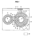
- Figs. 1 and 2 are respectively a plan view and a perspective view of one embodiment according to the present invention.
- Reaction cuvettes 35 are arranged on a reaction disk 36 along its circumference.
- a reagent disk 42 is disposed inside the reaction disk 36, and a reagent disk 41 is disposed outside the reaction disk 36.
- a plurality of reagent containers 40 are loadable on each of the reagent disks 41, 42 along its circumference.
- One reagent container 40 contains two kinds of reagents.
- a conveyer mechanism 12 for moving a rack 11 with sample containers 10 loaded thereon is installed near the reaction disk 36.
- Rails 25, 26 are laid to extend between both the reagent disks 41 and 42 at a level above them.
- Reagent probes 20, 21 are disposed on the rail 25 to be movable not only in the direction parallel to the rail 25, but also in the vertical direction.
- Reagent probes 22, 23 are disposed on the rail 26 to be movable in the 3-axis directions with respect to the rail 26.
- the reagent probes 20, 21, 22 and 23 are connected to a reagent pump 24.
- sample probes 15, 16 are disposed to be rotatable in respective planes and movable in the vertical direction.
- the sample probes 15, 16 are each moved along a circular arc about a rotary shaft to alternately dispense a sample from the sample container into the reaction cuvettes.
- the sample probes 15, 16 include mechanisms capable of changing the probe heights, and perform dispensing operations at the timings and the probe heights both properly adjusted in accordance with a preset program so that the movements of both the sample probes will not interfere with each other.
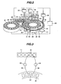
- FIG. 3 shows, from above an analyzer, the paths along which the sample probes move
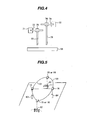
- Fig. 4 shows structures of the sample probes from the front of the analyzer
- Fig. 5 is a perspective view showing a mechanism for moving the sample probes.
- the sample probes 15, 16 are each moved between one sample container 61 placed on the rack 11 and locating in a position where a sample is to be sucked by the sample probe and one 62 of the reaction cuvettes 35 locating in a position where a sample is to be discharged from the sample probe.
- the sample probe 15 is movable among three points, i.e., the sample container 61, the reaction cuvette 62, and a washing position 63.
- Numeral 65 denotes the path along which the sample probe 15 moves.
- the sample probe 16 is movable among three points, i.e., the sample container 61, the reaction cuvette 62, and a washing position 64.
- Numeral 66 denotes the path along which the sample probe 16 moves.
- the sample probe 15 is movable along a rail 71 by a drive source (not shown) in the back-and-forth direction between the sample container 61 and the reaction cuvette 62, while it is movable along a rail 73 by a drive source (not shown) in the left-and-right direction between the washing position 63 and the sample container 61 or the reaction cuvette 62.
- the operation of moving the sample probe 15 in the back-and-forth direction and the operation of moving the sample probe 15 in the left-and-right direction are performed such that one of those operations follows the other.
- a sample probe head 75 is movable in a plane constituted by both the rails 71, 73, and a nozzle 77 having a vertical moving mechanism enables the sample probe head 75 to move in a three-dimensional space.
- the sample probe 16 is movable along a rail 72 by a drive source (not shown) in the back-and-forth direction between the sample container 61 and the reaction cuvette 62, while it is movable along a rail 74 by a drive source (not shown) in the left-and-right direction between the washing position 64 and the sample container 61 or the reaction cuvette 62.
- the operation of moving the sample probe 16 in the back-and-forth direction and the operation of moving the sample probe 16 in the left-and-right direction are performed such that one of those operations follows the other.
- a sample probe head 76 is movable in a plane constituted by both the rails 72, 74, and a nozzle 78 having a vertical moving mechanism enables the sample probe 76 head to move in a three-dimensional space.
- each of the sample probes 15, 16 has a liquid level detecting function and a clogging detecting function. Further, the sample probes 15, 16 are connected to a sample pump 14, and operations of the sample probes 15, 16 are controlled by drive systems independent from each other.
- the reaction disk 36 there are arranged mixing units 30, 31, a light source 50, an optical detector 51, and a cuvette washing mechanism 45.
- the cuvette washing mechanism 45 is connected to a washing pump 46. Washing ports 54 are disposed within respective areas where the sample probes 15, 16, the reagent probes 20, 21, 22 and 23, and the mixing units 30, 31 are movable.
- a sample pump 14, the reagent pump 24, the washing pump 46, the optical detector 51, the reaction disk 36, the reagent disk 41, the reagent probes 20, 21, 22 and 23, and the sample probes 15, 16 are each connected to a controller 60.
- a sample to be analyzed such as blood
- the sample container 10 is placed on the rack 11 and then conveyed by the conveyer mechanism 12.
- the sample in the sample container 61 is sucked by the sample probe 15 or 16 and then pipetted into the reaction cuvette 62.
- the sample probe 15 is initially positioned in the washing position 63, and the sample probe 16 is initially positioned in the washing position 64.
- the sample probe 15 is moved on the rails 71 and 73 to the sample suction position (i.e., the position of the sample container 61) where the sample probe head 75 is descended toward the sample container 61 from above it. After sucking the sample, the sample probe head 75 ascends and the sample probe 15 is moved to the sample discharge position (i.e., the position of the reaction cuvette 62) where the sucked sample is discharged into the reaction cuvette 62. Similarly, the sample probe 16 is moved on the rails 72 and 74 to the sample suction position where the sample probe head 76 is descended toward the sample container 61 from above it. After sucking the sample, the sample probe head 76 ascends and the sample probe 16 is moved to the sample discharge position where the sucked sample is discharged into the reaction cuvette 62.
- the sample probe 15 when sucking the sample by the sample probe 15, for example, the sample probe 15 is moved to the sample suction position where the sample is sucked from the sample container 61. Then, the sample probe 15 is moved to the sample discharge position where the sucked sample is discharged into the reaction cuvette 62. In parallel to the movement of the sample probe 15 to the reaction cuvette 62, the sample probe 16 starts moving from the washing position 64 toward the sample container 61. At this time, to prevent the sample probes 15, 16 from colliding with each other, the sample probe 15 is moved toward the reaction cuvette 62 via the washing position 63.
- the sample probe 16 is moved toward the reaction cuvette 62 via the washing position 64 for discharge of the sucked sample.
- the time interval of sucking the sample from the sample container can be shortened.
- Figs. 7 and 5 The difference between Figs. 7 and 5 resides in that a curved rail 101 following the movement paths of the sample probes is employed in Fig. 5 , while straight rails (72-74) extending along two axes are provided in Fig. 7 to move the sample probes in a plane.
- Fig. 8 the interference between the sample probe heads 75 and 76 is avoided by using two pairs of straight rails intersecting at an obtuse angle instead of avoiding the interference (contact) between the two sample probes by using the curved rail 101 in Fig. 5 and by using two pairs of straight rails intersecting at a right angle in Fig. 7 .
- the rack 11 is conveyed by the conveyer mechanism 12 such that the next sample container comes to the sample suction position.
- the sampling position can also be adjusted by providing a dispensing arm on the moving mechanism and controlling the dispensing arm to rotate or translate as desired.
- a certain amount of reagent is pipetted from the reagent container 40 placed on the reagent disk 41 or 42 into the reaction cuvette by the reagent probe 20, 21, 22 or 23.
- a mixture of the sample and the reagent is stirred by the mixing unit 30 or 31 to develop a reaction for a predetermined time, and is subjected to measurement by the optical detector 51.
- a measured result is outputted to a control computer (not shown). If there still remains a requested measurement item, the above-described sampling steps are repeated. More specifically, while the sample probe 15 discharges the sucked sample into the reaction cuvette 35, the sample probe 16 sucks the sample from the sample container 10.
- the sample probe 15 or 16 sucks the sample from the next sample container 10. Such a sampling process by the sample probes 15, 16 is repeated until sampling for all the measurement items set for all of the sample containers 10 loaded on the rack 11 is completed.
- the sample probes 15, 16 and the reagent probes 20, 21, 22 and 23 can be operated in any desired combinations. Therefore, even when one of the sample probes 15, 16 has failed to continue the operation because of any abnormality, the analysis can be continued for all the reagent items arranged on the analyzer by using the other sample probe.
- the analysis can be started by setting only the sample probe free from abnormality to be effective.
- the clogging detection function of one of the sample probes 15, 16 determines that any sample clogging factor exists in the sample container 10 or that the sample is exhausted, the sample probe for which the clogging has been detected is moved to the washing port 54 for washing of its flow passage, whereas the other sample probe can be controlled so as to stop the sucking operation from the relevant sample container and to make a shift to the sucking operation from the next sample container 10 on the rack 11. Even in the case where the status judgment shows that the sample container 10 on the rack 11 cannot be moved to the sample suction position in time, the analyzing operation can be continued without causing useless vacant cycles because the sample probe 15 or 16 is able to suck the sample from any desired one of plural positions.
- the amount of the sample in the sample container is very small such as the case of a sample taken from an infant, it is possible to reduce the amount of a dummy which is required in the sampling operation to prevent thinning of the sample in the sample probe and is discarded into a washing tank without being discharged into the reaction cuvette 35, by using only one of the sample probes 15 and 16.
- the present invention can provide an automatic analyzer, in which an analyzer includes a plurality of sample dispensing mechanisms capable of operating independently of each other, and which has a high processing capability per hour and a high value added.
Landscapes
- Chemical & Material Sciences (AREA)
- Physics & Mathematics (AREA)
- Health & Medical Sciences (AREA)
- Life Sciences & Earth Sciences (AREA)
- Analytical Chemistry (AREA)
- Biochemistry (AREA)
- General Health & Medical Sciences (AREA)
- General Physics & Mathematics (AREA)
- Immunology (AREA)
- Pathology (AREA)
- Chemical Kinetics & Catalysis (AREA)
- Automatic Analysis And Handling Materials Therefor (AREA)
Applications Claiming Priority (2)
| Application Number | Priority Date | Filing Date | Title |
|---|---|---|---|
| JP2003074751A JP3972012B2 (ja) | 2003-03-19 | 2003-03-19 | 試料分注機構及びそれを備えた自動分析装置 |
| JP2003074751 | 2003-03-19 |
Publications (2)
| Publication Number | Publication Date |
|---|---|
| EP1460432A1 EP1460432A1 (en) | 2004-09-22 |
| EP1460432B1 true EP1460432B1 (en) | 2013-06-05 |
Family
ID=32821335
Family Applications (1)
| Application Number | Title | Priority Date | Filing Date |
|---|---|---|---|
| EP04002367.3A Expired - Lifetime EP1460432B1 (en) | 2003-03-19 | 2004-02-03 | Sample dispensing apparatus and automatic analyzer including the same |
Country Status (3)
| Country | Link |
|---|---|
| US (5) | US7824915B2 (ja) |
| EP (1) | EP1460432B1 (ja) |
| JP (1) | JP3972012B2 (ja) |
Cited By (2)
| Publication number | Priority date | Publication date | Assignee | Title |
|---|---|---|---|---|
| CN108291919A (zh) * | 2015-08-28 | 2018-07-17 | 株式会社日立高新技术 | 自动分析装置及试剂瓶的搬入方法 |
| EP3584581B1 (en) * | 2018-06-19 | 2023-09-13 | Jeol Ltd. | Automatic analyzer and automatic analysis method |
Families Citing this family (30)
| Publication number | Priority date | Publication date | Assignee | Title |
|---|---|---|---|---|
| JP4812352B2 (ja) * | 2005-07-21 | 2011-11-09 | 株式会社東芝 | 自動分析装置及びその分注方法 |
| JP2008180538A (ja) * | 2007-01-23 | 2008-08-07 | Olympus Corp | 分析装置 |
| JP2008209339A (ja) * | 2007-02-28 | 2008-09-11 | Hitachi High-Technologies Corp | 自動分析装置 |
| JP5583337B2 (ja) * | 2007-12-28 | 2014-09-03 | ベックマン コールター, インコーポレイテッド | 自動分析装置及びその分注方法 |
| ES2371185B1 (es) * | 2008-05-30 | 2012-08-07 | Grifols, S.A. | Aparato para la realizacion automatica de analisis de muestras en tarjetas de gel. |
| CN101721937B (zh) | 2008-10-31 | 2012-06-27 | 深圳迈瑞生物医疗电子股份有限公司 | 搅拌系统及其工作方法 |
| JP5373561B2 (ja) * | 2008-11-17 | 2013-12-18 | シスメックス株式会社 | 搬送装置及びこれを用いた検体分析装置 |
| DE112010000784B4 (de) * | 2009-01-29 | 2013-10-31 | Hitachi High-Technologies Corporation | Automatischer Analysator |
| JP5757694B2 (ja) * | 2010-05-31 | 2015-07-29 | アークレイ株式会社 | 搬送装置、搬送方法、搬送プログラム、分析装置、分析方法、および試料分析プログラム |
| ES2610468T3 (es) * | 2010-07-23 | 2017-04-27 | Beckman Coulter, Inc. | Sistema o método para incluir unidades analíticas |
| DE102010037084A1 (de) * | 2010-08-20 | 2012-02-23 | LCTech GmbH | Probenaufbereitungssystem sowie ein Verfahren zur Bearbeitung einer Probe |
| JP5613522B2 (ja) * | 2010-10-12 | 2014-10-22 | シスメックス株式会社 | 検体分析装置 |
| WO2013058170A1 (ja) * | 2011-10-18 | 2013-04-25 | 株式会社 日立ハイテクノロジーズ | 自動分析装置 |
| CN104040355B (zh) | 2011-11-01 | 2015-11-25 | 沙特阿拉伯石油公司 | 用于光学照相测量的多试管自动进样器 |
| EP2746775B1 (en) * | 2012-12-19 | 2019-09-04 | F.Hoffmann-La Roche Ag | Device and process for transferring reaction vessels |
| JP6153759B2 (ja) * | 2013-04-10 | 2017-06-28 | 株式会社日立ハイテクノロジーズ | 自動分析装置 |
| CN103675316A (zh) * | 2013-12-24 | 2014-03-26 | 苏州长光华医生物医学工程有限公司 | 全自动血型仪器加样装置 |
| JP6521567B2 (ja) * | 2014-02-27 | 2019-05-29 | キヤノンメディカルシステムズ株式会社 | 臨床検査装置 |
| JP6104843B2 (ja) * | 2014-03-28 | 2017-03-29 | シスメックス株式会社 | 検体分析装置 |
| US10761000B2 (en) * | 2014-07-18 | 2020-09-01 | Hitachi High-Tech Corporation | Liquid stirring method |
| JP6611569B2 (ja) * | 2015-11-24 | 2019-11-27 | キヤノンメディカルシステムズ株式会社 | 自動分析装置 |
| WO2017199432A1 (ja) * | 2016-05-20 | 2017-11-23 | 株式会社島津製作所 | 前処理装置及びその前処理装置を備えた分析システム |
| AU2018230514B2 (en) * | 2017-03-09 | 2021-04-29 | Hologic, Inc. | Systems and methods for automated preparation of biological specimens |
| JP6865887B2 (ja) * | 2018-02-28 | 2021-04-28 | 株式会社日立ハイテク | 自動分析装置 |
| US20210025791A1 (en) | 2018-03-16 | 2021-01-28 | Inveox Gmbh | Sample processing system and method for automatically processing histological samples |
| CN109061214B (zh) * | 2018-10-31 | 2023-12-19 | 江苏卓微生物科技有限公司 | 多孔进样装置 |
| US11933802B2 (en) | 2019-04-26 | 2024-03-19 | Hitachi High-Tech Corporation | Automatic analysis device |
| CN111781338A (zh) * | 2020-07-10 | 2020-10-16 | 屈梅 | 一种血液科专用血液检查仪 |
| CN112881356B (zh) * | 2021-01-18 | 2022-06-28 | 上海雄图生物科技有限公司 | 高通量荧光免疫定量poct分析装置 |
| CN114384262B (zh) * | 2021-12-30 | 2025-09-26 | 深圳市新产业生物医学工程股份有限公司 | 吸液装置和样本分析仪 |
Family Cites Families (21)
| Publication number | Priority date | Publication date | Assignee | Title |
|---|---|---|---|---|
| US4276260A (en) * | 1980-01-28 | 1981-06-30 | Coulter Electronics, Inc. | Fluid transfer mechanism |
| JPS5782769A (en) * | 1980-11-10 | 1982-05-24 | Hitachi Ltd | Automatic analyzing device |
| AU585033B2 (en) * | 1986-07-04 | 1989-06-08 | Tosoh Corporation | Quantitative dispenser for a liquid |
| JPH06103315B2 (ja) * | 1987-08-14 | 1994-12-14 | 株式会社東芝 | 自動化学分析装置の分注ノズル装置 |
| US5178834A (en) * | 1989-07-19 | 1993-01-12 | Tosoh Corporation | Automatic immunoassay analyzer |
| JPH03140869A (ja) * | 1989-10-26 | 1991-06-14 | Toshiba Corp | 自動化学分析装置 |
| JP2927082B2 (ja) * | 1990-11-28 | 1999-07-28 | 株式会社日立製作所 | 液体サンプル用分析方法および分析装置 |
| DE59306558D1 (de) * | 1992-04-06 | 1997-07-03 | Hoffmann La Roche | Analysenvorrichtung |
| EP0601213A1 (de) * | 1992-10-29 | 1994-06-15 | Hamilton Bonaduz AG | Vorrichtung zum Transportieren von Waren |
| JP3140869B2 (ja) | 1992-12-03 | 2001-03-05 | 株式会社東芝 | プリント配線板設計支援システム |
| CA2113785A1 (en) * | 1993-01-29 | 1994-07-30 | Teruaki Itoh | Sample sorting apparatus |
| AU4982093A (en) * | 1993-08-31 | 1995-03-22 | Abbott Laboratories | Pipetting apparatus equipped with closure detection function |
| DE69515565T2 (de) * | 1994-07-15 | 2000-11-02 | Dade Chemistry Systems Inc., Deerfield | Analysevorrichtung |
| US5885529A (en) * | 1996-06-28 | 1999-03-23 | Dpc Cirrus, Inc. | Automated immunoassay analyzer |
| US5942694A (en) * | 1996-11-12 | 1999-08-24 | Beckman Instruments, Inc. | Pressure detector for chemical analyzers |
| JP2001066316A (ja) | 1999-08-30 | 2001-03-16 | Olympus Optical Co Ltd | 分注装置 |
| US7015042B2 (en) * | 2001-07-27 | 2006-03-21 | Dade Behring Inc. | Increasing throughput in an automatic clinical analyzer by partitioning assays according to type |
| JP5193408B2 (ja) * | 2001-09-13 | 2013-05-08 | ベックマン コールター, インコーポレイテッド | 自動分析装置 |
| WO2003065049A2 (en) * | 2002-01-25 | 2003-08-07 | Innovadyne Technologies, Inc. | Low volume, non-contact liquid dispensing method |
| JP3740428B2 (ja) * | 2002-03-29 | 2006-02-01 | アロカ株式会社 | 検体前処理システム |
| WO2004003219A2 (en) * | 2002-06-28 | 2004-01-08 | Igen International, Inc. | Improved assay systems and components |
-
2003
- 2003-03-19 JP JP2003074751A patent/JP3972012B2/ja not_active Expired - Lifetime
-
2004
- 2004-02-03 EP EP04002367.3A patent/EP1460432B1/en not_active Expired - Lifetime
- 2004-02-19 US US10/780,743 patent/US7824915B2/en active Active
-
2010
- 2010-09-30 US US12/895,040 patent/US8197754B2/en not_active Expired - Fee Related
-
2012
- 2012-05-17 US US13/473,666 patent/US8691148B2/en not_active Expired - Lifetime
-
2014
- 2014-02-20 US US14/185,037 patent/US9817013B2/en not_active Expired - Fee Related
-
2017
- 2017-10-12 US US15/730,947 patent/US10309979B2/en not_active Expired - Lifetime
Cited By (3)
| Publication number | Priority date | Publication date | Assignee | Title |
|---|---|---|---|---|
| CN108291919A (zh) * | 2015-08-28 | 2018-07-17 | 株式会社日立高新技术 | 自动分析装置及试剂瓶的搬入方法 |
| CN108291919B (zh) * | 2015-08-28 | 2021-09-14 | 株式会社日立高新技术 | 自动分析装置及试剂瓶的搬入方法 |
| EP3584581B1 (en) * | 2018-06-19 | 2023-09-13 | Jeol Ltd. | Automatic analyzer and automatic analysis method |
Also Published As
| Publication number | Publication date |
|---|---|
| US20110014085A1 (en) | 2011-01-20 |
| US10309979B2 (en) | 2019-06-04 |
| US8691148B2 (en) | 2014-04-08 |
| JP3972012B2 (ja) | 2007-09-05 |
| EP1460432A1 (en) | 2004-09-22 |
| US7824915B2 (en) | 2010-11-02 |
| US20140170022A1 (en) | 2014-06-19 |
| US8197754B2 (en) | 2012-06-12 |
| US20040245275A1 (en) | 2004-12-09 |
| US9817013B2 (en) | 2017-11-14 |
| US20120230873A1 (en) | 2012-09-13 |
| US20180038882A1 (en) | 2018-02-08 |
| JP2004279356A (ja) | 2004-10-07 |
Similar Documents
| Publication | Publication Date | Title |
|---|---|---|
| US10309979B2 (en) | Sample dispensing apparatus and automatic analyzer including the same | |
| US6409968B1 (en) | Automatic analysis apparatus for biological fluid sample and automatic analysis method therefor | |
| US11524287B2 (en) | Automatic pipetting device for transferring samples and/or reagents and method for transferring liquid samples and/or reagents | |
| EP2187220B1 (en) | Transporting apparatus and specimen analyzing apparatus | |
| JP5850625B2 (ja) | 分析装置及び位置確認方法 | |
| US8343772B2 (en) | Specimen processing device, specimen conveyance device, and specimen conveyance method | |
| JP2004279357A (ja) | 自動分析装置 | |
| WO2002059624A1 (fr) | Analyseur automatique | |
| EP3974837B1 (en) | Automatic analysis device | |
| CN113848341A (zh) | 样本分析设备 | |
| WO2007139212A1 (ja) | 自動分析装置 | |
| WO2022176556A1 (ja) | 自動分析装置、および自動分析装置における検体の吸引方法 | |
| JP4929317B2 (ja) | 自動分析装置 | |
| JP6034051B2 (ja) | 自動分析装置 | |
| JP4408404B2 (ja) | 自動分析装置 | |
| JP4393481B2 (ja) | 自動分析装置 | |
| JP4416763B2 (ja) | 自動分析装置 | |
| JP4366380B2 (ja) | 自動分析装置 | |
| EP4592685A1 (en) | Automated analysis device | |
| WO2023095587A1 (ja) | 自動分析装置 | |
| CN119555945A (zh) | 自动分析装置及适配器 | |
| JP2010117176A (ja) | 分析装置とその分注制御方法 | |
| JP2008064769A (ja) | 自動分析装置 |
Legal Events
| Date | Code | Title | Description |
|---|---|---|---|
| PUAI | Public reference made under article 153(3) epc to a published international application that has entered the european phase |
Free format text: ORIGINAL CODE: 0009012 |
|
| AK | Designated contracting states |
Kind code of ref document: A1 Designated state(s): AT BE BG CH CY CZ DE DK EE ES FI FR GB GR HU IE IT LI LU MC NL PT RO SE SI SK TR |
|
| AX | Request for extension of the european patent |
Extension state: AL LT LV MK |
|
| 17P | Request for examination filed |
Effective date: 20050316 |
|
| AKX | Designation fees paid |
Designated state(s): DE FR GB |
|
| 17Q | First examination report despatched |
Effective date: 20071127 |
|
| GRAP | Despatch of communication of intention to grant a patent |
Free format text: ORIGINAL CODE: EPIDOSNIGR1 |
|
| RIC1 | Information provided on ipc code assigned before grant |
Ipc: G01N 35/02 20060101ALI20121206BHEP Ipc: G01N 35/10 20060101AFI20121206BHEP Ipc: G01N 35/00 20060101ALI20121206BHEP |
|
| GRAS | Grant fee paid |
Free format text: ORIGINAL CODE: EPIDOSNIGR3 |
|
| GRAA | (expected) grant |
Free format text: ORIGINAL CODE: 0009210 |
|
| AK | Designated contracting states |
Kind code of ref document: B1 Designated state(s): DE FR GB |
|
| REG | Reference to a national code |
Ref country code: GB Ref legal event code: FG4D |
|
| REG | Reference to a national code |
Ref country code: DE Ref legal event code: R096 Ref document number: 602004042325 Country of ref document: DE Effective date: 20130801 |
|
| PLBE | No opposition filed within time limit |
Free format text: ORIGINAL CODE: 0009261 |
|
| STAA | Information on the status of an ep patent application or granted ep patent |
Free format text: STATUS: NO OPPOSITION FILED WITHIN TIME LIMIT |
|
| 26N | No opposition filed |
Effective date: 20140306 |
|
| REG | Reference to a national code |
Ref country code: DE Ref legal event code: R097 Ref document number: 602004042325 Country of ref document: DE Effective date: 20140306 |
|
| GBPC | Gb: european patent ceased through non-payment of renewal fee |
Effective date: 20140203 |
|
| PG25 | Lapsed in a contracting state [announced via postgrant information from national office to epo] |
Ref country code: GB Free format text: LAPSE BECAUSE OF NON-PAYMENT OF DUE FEES Effective date: 20140203 |
|
| REG | Reference to a national code |
Ref country code: FR Ref legal event code: PLFP Year of fee payment: 13 |
|
| REG | Reference to a national code |
Ref country code: FR Ref legal event code: PLFP Year of fee payment: 14 |
|
| REG | Reference to a national code |
Ref country code: FR Ref legal event code: PLFP Year of fee payment: 15 |
|
| REG | Reference to a national code |
Ref country code: DE Ref legal event code: R082 Ref document number: 602004042325 Country of ref document: DE Representative=s name: STREHL SCHUEBEL-HOPF & PARTNER MBB PATENTANWAE, DE Ref country code: DE Ref legal event code: R081 Ref document number: 602004042325 Country of ref document: DE Owner name: HITACHI HIGH-TECH CORPORATION, JP Free format text: FORMER OWNER: HITACHI HIGH-TECHNOLOGIES CORPORATION, TOKYO, JP |
|
| PGFP | Annual fee paid to national office [announced via postgrant information from national office to epo] |
Ref country code: FR Payment date: 20220118 Year of fee payment: 19 |
|
| PGFP | Annual fee paid to national office [announced via postgrant information from national office to epo] |
Ref country code: DE Payment date: 20221229 Year of fee payment: 20 |
|
| PG25 | Lapsed in a contracting state [announced via postgrant information from national office to epo] |
Ref country code: FR Free format text: LAPSE BECAUSE OF NON-PAYMENT OF DUE FEES Effective date: 20230228 |
|
| REG | Reference to a national code |
Ref country code: DE Ref legal event code: R071 Ref document number: 602004042325 Country of ref document: DE |