EP1460342B1 - Cooking Apparatus - Google Patents
Cooking Apparatus Download PDFInfo
- Publication number
- EP1460342B1 EP1460342B1 EP03257336A EP03257336A EP1460342B1 EP 1460342 B1 EP1460342 B1 EP 1460342B1 EP 03257336 A EP03257336 A EP 03257336A EP 03257336 A EP03257336 A EP 03257336A EP 1460342 B1 EP1460342 B1 EP 1460342B1
- Authority
- EP
- European Patent Office
- Prior art keywords
- tray
- cooking apparatus
- set forth
- heater
- terminals
- Prior art date
- Legal status (The legal status is an assumption and is not a legal conclusion. Google has not performed a legal analysis and makes no representation as to the accuracy of the status listed.)
- Expired - Fee Related
Links
Images


Classifications
-
- A—HUMAN NECESSITIES
- A47—FURNITURE; DOMESTIC ARTICLES OR APPLIANCES; COFFEE MILLS; SPICE MILLS; SUCTION CLEANERS IN GENERAL
- A47J—KITCHEN EQUIPMENT; COFFEE MILLS; SPICE MILLS; APPARATUS FOR MAKING BEVERAGES
- A47J37/00—Baking; Roasting; Grilling; Frying
-
- F—MECHANICAL ENGINEERING; LIGHTING; HEATING; WEAPONS; BLASTING
- F24—HEATING; RANGES; VENTILATING
- F24C—DOMESTIC STOVES OR RANGES ; DETAILS OF DOMESTIC STOVES OR RANGES, OF GENERAL APPLICATION
- F24C15/00—Details
- F24C15/16—Shelves, racks or trays inside ovens; Supports therefor
- F24C15/166—Shelves, racks or trays inside ovens; Supports therefor with integrated heating means
-
- F—MECHANICAL ENGINEERING; LIGHTING; HEATING; WEAPONS; BLASTING
- F24—HEATING; RANGES; VENTILATING
- F24C—DOMESTIC STOVES OR RANGES ; DETAILS OF DOMESTIC STOVES OR RANGES, OF GENERAL APPLICATION
- F24C15/00—Details
- F24C15/003—Details moisturising of air
-
- F—MECHANICAL ENGINEERING; LIGHTING; HEATING; WEAPONS; BLASTING
- F24—HEATING; RANGES; VENTILATING
- F24C—DOMESTIC STOVES OR RANGES ; DETAILS OF DOMESTIC STOVES OR RANGES, OF GENERAL APPLICATION
- F24C7/00—Stoves or ranges heated by electric energy
- F24C7/06—Arrangement or mounting of electric heating elements
Definitions
- the present invention relates to a cooking apparatus, and more particularly to a cooking apparatus which improves heating efficiency.
- a cooking apparatus includes a cooking cavity to receive foods to be cooked, and a heating device installed in the cooking cavity or in an additional compartment isolated from the cooking cavity.
- a microwave oven which is a kind of cooking apparatus, includes a cooking cavity defining a space for cooking foods therein, and a machine room isolated from the cooking cavity having a magnetron generating microwaves. The microwaves are then introduced into the cooking cavity to cook the food.
- microwave ovens where cooking is performed by only the microwaves from the magnetron, it is difficult to achieve a satisfactory cooking result because food is not evenly irradiated with the microwaves due to factors such as water content, distribution, and size of the food. Further, it is impossible to perform various kinds of cooking.
- a microwave oven has been proposed, in which the cooking cavity includes upper and lower heaters, to quickly and evenly cook food in the cooking cavity by heat generated from the upper and lower heaters as well as microwaves generated from the magnetron and to allow various kinds of cooking to be performed.
- the food can be cooked by heat generated from the upper and lower heaters, as in a grill oven.
- the cooking cavity is not only reduced in its capacity but also complicated in its structure, thereby precluding efficient employment of the cooking cavity and increasing production cost and time.
- a tray in a cooking cavity is separated from a lower heater, so that heat generated from the lower heater must be transmitted to the food through the tray.
- heating efficiency is decreased and sufficient heat energy cannot be transmitted to a lower surface of the food, thereby increasing electric power consumption.
- the food since the amount of heat energy transmitted to upper and lower parts of the food are different from each other, the food must be periodically turned over to evenly cook upper and lower parts of the food, thereby causing the user inconvenience.
- a temperature at a part of the microwave oven around the lower heater becomes very high, a cooling fan operating at a high speed must be provided in the microwave oven to cool the heated part, thereby causing unpleasant noise due to the high-speed operation of the cooling fan.
- a tray disposed to be spaced from a lower heater of the conventional cooking apparatus has uneven temperature distribution between its upper surface and its lower surface facing a lower heater, food placed on the tray is not evenly cooked.
- EP-A-0,298,567 discloses a tray for an oven comprising upper and lower metal sheets having a heating foil located therebetween, wherein the heating foil includes a resistive heating element arranged within an insulating material. This document forms the pre-characterising portion of the claims appended hereto.
- the present invention provides a microwave oven which includes a socket for power supply provided at a rear wall of its cooking cavity and a tray having a heater therein so as to cause the tray to generate heat by the heater.
- a cooking apparatus comprising: a cooking cavity; at least one pair of support rails respectively included at both side walls of the cooking cavity; a tray on which food is placed; a heater to directly heat the tray to cook the food by activation of the heater, having a pair of terminals; and at least one socket included at a rear wall of the cooking cavity allowing electric power to be supplied to the heater when connected to the terminals; characterised in that: the heater comprises: a conductive film coated on a lower surface of the tray; and first and second opposing electrodes connected to the conductive film, the conductive film heating as a result of electric current flowing through the conductive film between the first and second electrodes.
- each of the first and second electrodes may be divided at its center portion, and both the divided electrode segments may be spaced from each other by a certain distance with a conductive wire connected therebetween, in order to prevent a center area of the conductive film from being heated more than its peripheral area.
- each of the first and second electrodes may be bent outward to have an arched shape, in order to prevent a center area of the conductive film from being heated more than its peripheral area.
- the pair of terminals may be positioned at a side of the tray such that inner ends of the terminals are connected to the first and second electrodes and outer ends of the terminals are outwardly projected from the tray.
- the pair of terminals insert into the socket corresponding to the support rails to allow the tray to be heated by electric current flowing through the conductive film between the first and second electrode.
- the lower surface of the tray may be covered with a cover plate to prevent the heater attached to the tray from being exposed.
- Each of the pair of terminals may be surrounded with an insulating sheath except at its opposite ends, and the lower surface of the tray and the cover plate may be provided with a pair of grooves, respectively, to define a pair of holes, in which the pair of terminals are received.
- Sealing material may be applied to the grooves of the tray and the cover plate so as to prevent moisture from infiltrating into the heater through the grooves.
- the at least one pair of support rails may include a plurality of pairs of support rails, which are positioned at both side walls of the cooking cavity to be vertically spaced from one another by a certain distance.
- the at least one socket may include a plurality of sockets, which are positioned at the rear wall of the cooking cavity to correspond to the plurality of pairs of support rails.
- the cooking apparatus may include an upper heater fixed to an upper portion of the rear wall of the cooking cavity to cook food in cooperation with the heater provided at the tray.
- Each of the plurality of sockets may include a micro switch, which is turned on and off when the terminals are inserted into and separated from one of the sockets, to control electric current supplied to the heater by registering which of the sockets the heater is inserted into.
- the tray may include a bottom plate and a side wall upwardly extended from a peripheral edge of the bottom plate, and the heater may be positioned on a lower surface of the bottom plate.
- the cooking apparatus may include a grill plate placed on an upper end of the tray.
- the side wall of the tray may include a stepped portion at a predetermined height of its inner surface, which serves as a water level mark.
- FIG. 1 is a perspective view showing a cooking apparatus 100 according to an embodiment of the present invention, which is provided with a tray having a heater therein.
- the cooking apparatus 100 includes a cabinet 1 providing an appearance of the cooking apparatus 100, a cooking cavity 10 in the cabinet 1, a door 2 to open and close a front face of the cooking cavity 10, and a control panel 3 attached to a front face of the cabinet 1 adjacent to the door 2.
- the cooking cavity 10 is defined by a rear wall 11, left and right walls 12 and 13, a top wall 14, and a bottom wall 15.
- the cooking cavity 10 is provided with a heater 4 close to the top wall 14 at the rear wall 11, to emit high-temperature heat downwardly.
- the left and right walls 12 and 13 of the cooking cavity 10 are provided with a pair of upper support rails 21, a pair of intermediate support rails 22 and a pair of lower support rails 23, which are spaced from each other by a certain distance.
- the rear wall 11 of the cooking cavity 10 is provided with an upper socket 24, an intermediate socket 25, and a lower socket 26, which are positioned just below the upper, intermediate and lower support rails 21, 22 and 23, respectively.
- the support rails 21, 22, and 23 and the sockets 24, 25, and 26 are described to be disposed at an upper position, an intermediate position and a lower position of the cooking cavity, the number and the position of the support rails 21, 22, and 23 and the sockets 24, 25, and 26 may be changed depending on a size of the cooking cavity.
- the right wall 13 of the cooking cavity 10 is further provided with a temperature sensor 27 to detect a temperature in the cooking cavity 10 and thus control cooking of food in the cooking cavity 10.
- the tray 30 includes a bottom plate 31 and an integral side wall 32 upwardly extended from a peripheral edge of the bottom plate 31 to have a substantially rectangular form.
- the side wall 32 is integrally provided at its upper end with a flange 33 extended outwardly by a certain length. Accordingly, the tray 30, on which food is placed, can be easily supported by any one pair of support rails 21, 22, and 23 among the upper, intermediate and lower support rails 21, 22 and 23 formed at the left and right walls 12 and 13, so as to cook the food in the cooking cavity 10.
- Figures 2 and 3 are side cross-sectional views showing a heater installed on an underside of the tray, which serves to cook food on the tray in cooperation with an upper heater fixedly installed on an upper portion of the cooking cavity, in which Figure 2 is a cross-sectional view taken along line II-II of Figure 1, and Figure 3 is a cross-sectional view taken along line III-III of Figure 1.
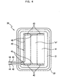
- Figure 4 is a cross-sectional view taken along line IV-IV of Figure 3.
- the tray 30 includes a heater 40 shown in Figure 4, at its bottom plate 31, which is formed into a plate-shape to provide a heating surface.
- the heater 40 includes a thin conductive film 41 coated on its underside, first and second electrodes 42 and 43 disposed at both sides of the conductive film 41 to face each other, as shown in Figure 4, and a pair of terminals 44 shown in Figures 3 and 4, connected to the first and second electrodes 42 and 43 to allow electric power to be supplied to the heater 40.
- the conductive film 41 is produced from material, which allows electric current to flow between the first and second electrodes 42 and 43 through the shortest path, to generate heat by itself, and radiate the heat. Accordingly, the overall bottom plate 31 of the tray 30 on which the conductive film 41 is coated serves as a heating surface.
- the first electrodes 42 and the second electrodes 43 are electrically connected to the terminals 44. Consequently, when the terminals 44 are inserted in any one of the sockets 24, 25 and 26 of the cooking cavity 10 allowing external electric power to be supplied to the heater 40, the electric current flows between the first and second electrodes 42 and 43 through the conductive film 41. This causes the conductive film 41 to generate heat.
- each of the first and second electrodes 42 and 43 is divided into two electrodes to be spaced from each other by a certain distance.
- the center area "A" of the conductive film 41 is heated by heat transmitted from its surrounding areas, thereby allowing the conductive film 41 to be evenly heated to a high temperature.
- the center area "A" of the conductive film 41 may be evenly heated without the division of each of the first and second electrodes 42 and 43.
- each of the first and second electrodes 42 and 43 is bent outward to have an arched shape (not shown).
- a distance between the first and second electrodes 42 and 43 is increased at the center potion of the electrodes, compared to the structure at end portions of the electrodes. Accordingly, flow of electric current is relatively weakened at the center area "A" of the conductive film 41, thereby causing the conductive film 41 to be evenly heated.
- the terminals 44 are positioned on the underside of the tray 30 such that inner ends of the terminals 44 are connected to the first and second electrodes 42 and 43 and outer ends of the terminals 44 are projected from the tray 30. Therefore, when the outer ends of the terminals 44 are inserted into any one of the sockets 24, 25 and 26 installed on the rear wall 11 of the cooking cavity 10, the first and second electrodes 42 and 43 are supplied with electric power.
- the terminals 44 are surrounded with insulating sheaths 46 to prevent electricity leakage.
- the tray 30 includes a cover plate 50 at its lower surface covering the heater 40 so as to protect the heater 40 from external impact.
- the cover plate 50 is attached to the lower surface of the tray 30 by sealing material 34 such as silicon. Accordingly, by attaching the cover plate 50 to the tray 30, the conductive film 41 and the first and second electrodes 42 and 43 can be protected from infiltration of moisture and from breakage by external impact.
- the heater 40 according to the present invention is comprised of the conductive film 41, the first and second electrodes 42 and 43, and the terminals 44, the heater 40 can be remarkably decreased in its thickness and weight, thereby preventing considerable increase of overall thickness and weight of the tray 30. Furthermore, since the heater 40 is directly attached to the tray 30 so as to permit the tray 30 to generate heat by itself to cook food placed thereon, heating efficiency is considerably improved and power consumption is reduced.
- the tray 30 having the heater 40 installed thereon is made of metallic material having excellent heat transfer properties, such as aluminum and stainless steel.
- metallic material having excellent heat transfer properties, such as aluminum and stainless steel.
- Figure 5 is a fragmentary perspective view showing a part of the tray 30 in which the terminals 44 are installed to allow external power to be supplied to the heater.
- Figure 6 is a cross-sectional view showing the terminals 44 inserted in the socket.
- Figure 7 is a cross-sectional view taken along line VII-VII of Figure 6.
- the tray 30 is provided at its lower surface with a pair of semi-circular grooves 35.
- the cover plate 50 is provided with a pair of semi-circular grooves 51 at its portion corresponding to the semi-circular grooves 35 of the tray 30. Therefore, two holes defined between the semi-circular grooves 35 of the tray 30 and the semi-circular grooves 51 of the cover plate 50 receive the insulating sheaths 46 attached to outer surfaces of the terminals 44.
- Inner ends of the terminals 44 are attached to a lower surface of the bottom plate 31 of the tray 30 by spot welding, so as to connect the terminals 44 to the first and second electrodes 42 and 43.
- Outer ends of the terminals 44 are extended from the tray 30 together with a part of the insulating sheaths 46 surrounding the terminals 44, to enable the terminals 44 to be inserted into any one of the sockets 24, 25 and 26.
- Sealing material is applied to a gap between the terminals 44 and the semi-circular grooves 35 and 51 so as to prevent water or foreign substances from infiltrating into the heater 40 through the gap.
- the socket 24 includes a guide cover 28 protruded from the rear wall 11 of the cooking cavity 10 to guide insertion of the terminals 44 of the heater 40 (sockets 25 and 26 are similarly constructed but not shown). Socket terminals 29 are provided in the guide cover 28 and connected to the inserted terminals 44 of the heater 40 to allow external power to be supplied to the heater 40.
- Each of the sockets 24, 25 and 26 is provided in the guide cover 28 with a micro switch 60, which is turned on and off when the terminals 44 of the heater 40 are inserted into and separated from the one socket. Accordingly, the cooking apparatus 100 can register which of the support rails 21, 22 and 23 the tray 30 is placed on, and can thus control current supplied to the heater 40.
- the tray 30 is placed on the upper support rails 21, and the terminals 44 of the heater 40 are inserted into the upper socket 24, for the purpose of cooking of a small sized food, the tray 30 is positioned at a level closest to the upper heater 4 installed on the top wall of the cooking cavity 10. Consequently, even if the heater 40 of the tray 30 is applied with relatively little electric power, the food placed on the tray 30 can be quickly cooked.
- the tray 30 is placed on the intermediate support rails 22, and the terminals 44 of the heater 40 are inserted into the intermediate socket 25, for the purpose of cooking of a moderate sized food, the tray 30 is positioned at a level moderately remote from the upper heater 4. Consequently, the heater 40 of the tray 30 is applied with moderate electric power to cook the food placed on the tray 30.
- the tray 30 is placed on the lower support rails 23, and the terminals 44 of the heater 40 are inserted into the lower socket 26, for the purpose of cooking of a large sized food, the tray 30 is positioned at a level farthest from the upper heater 4. In this case, the heater 40 of the tray 30 is applied with high electric power to cook the large sized food placed on the tray 30.
- the cooking apparatus 100 is provided with a manual cooking temperature adjustment system. This would allow the user to cook foods with varying sizes at varying temperature. For instance, a food, such as a steak requiring little space and high cooking temperatures could be cooked on the upper support rails.
- the cooking apparatus 100 since the cooking apparatus 100 according to the present invention is designed to cook food by heat evenly generated through the bottom plate 31 of the tray 30 from the heater 40 attached to the bottom plate 31, the tray 30 may be used as a steaming container to steam food.
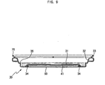
- the tray 30 includes a stepped portion 36 formed at an inner surface of the side wall 32, and a grill plate 70 to be placed on an upper side of the tray 30.
- the tray 30 is first filled with water up to the stepped portion 36 serving as a water level mark, and the grill plate 70 is placed on the upper side of the tray 30 with food placed on the grill 70.
- the tray 30 is placed on one pair of support rails, which is selected among the support rails 21, 22 and 23 according to a size of the food, and then pushed into the cooking cavity 10. As the tray 30 is pushed into the cooking cavity 10, the terminals 40 of the heater 40 attached to the tray 30 are inserted into the socket corresponding to the selected support rails, thereby allowing electric power to be supplied to the heater 40.
- the heater 40 activates and causes the conductive film 41 to generate heat, and thus the bottom plate 31 of the tray 30 is evenly heated. Accordingly, the water contained in the tray 30 is vaporized by the heated bottom plate 31, thereby steaming the food placed on the grill plate 70.
- the cooking apparatus 100 since the cooking apparatus 100 according to the present invention is constructed so the tray 30 is provided at its lower surface with the thin and light heater 40, and the heater 40 is selectively supplied with electric power from one of the sockets 24, 25 and 26, the cooking apparatus 100 may be used alone or in conjunction with another heating source such as a magnetron generating microwaves, depending on a kind and a size of food and a cooking manner.
- another heating source such as a magnetron generating microwaves
- the present invention provides a cooking apparatus 100, which includes a tray having a heater to cook food placed on the tray in a direct heating manner. Accordingly, heating efficiency of the cooking apparatus 100 is considerably improved, and thus electric power consumption is dramatically reduced, compared to a conventional cooking apparatus.
- a tray of the cooking apparatus 100 according to the present invention is provided at its lower surface with a thin heater attached thereto, thereby dispensing with a necessity for providing an additional heater in a cooking cavity of the cooking apparatus 100, an effective cooking space in the cooking cavity is increased, and manufacturing cost and time is reduced. Additionally, it is not necessary to operate a cooling fan for cooling a lower space of the cooking cavity at high speed and for a long period of time.
- a tray of the cooking apparatus 100 according to the present invention is evenly heated throughout its area to directly heat food placed on the tray, a lower part of the food is quickly and evenly cooked, and a procedure of turning food over during a grilling operation is not necessary.
- a tray of the cooking apparatus 100 according to the present invention is directly heated at its bottom plate, a steaming operation can be easily performed where the tray contains water therein.
Description
- The present invention relates to a cooking apparatus, and more particularly to a cooking apparatus which improves heating efficiency.
- Generally, a cooking apparatus includes a cooking cavity to receive foods to be cooked, and a heating device installed in the cooking cavity or in an additional compartment isolated from the cooking cavity. For example, a microwave oven, which is a kind of cooking apparatus, includes a cooking cavity defining a space for cooking foods therein, and a machine room isolated from the cooking cavity having a magnetron generating microwaves. The microwaves are then introduced into the cooking cavity to cook the food.
- In microwave ovens, where cooking is performed by only the microwaves from the magnetron, it is difficult to achieve a satisfactory cooking result because food is not evenly irradiated with the microwaves due to factors such as water content, distribution, and size of the food. Further, it is impossible to perform various kinds of cooking. To overcome such problems in conventional microwave ovens, a microwave oven has been proposed, in which the cooking cavity includes upper and lower heaters, to quickly and evenly cook food in the cooking cavity by heat generated from the upper and lower heaters as well as microwaves generated from the magnetron and to allow various kinds of cooking to be performed.
- In the microwave oven with the upper and lower heaters, when the upper and lower heaters are turned on after a tray, on which food is placed, is received in the cooking cavity between the upper and lower heaters, the food can be cooked by heat generated from the upper and lower heaters, as in a grill oven.
- However, in a conventional cooking apparatus provided with a plurality of heaters in its cooking cavity, the cooking cavity is not only reduced in its capacity but also complicated in its structure, thereby precluding efficient employment of the cooking cavity and increasing production cost and time.
- In addition, in the conventional cooking apparatus, a tray in a cooking cavity is separated from a lower heater, so that heat generated from the lower heater must be transmitted to the food through the tray. Thus, heating efficiency is decreased and sufficient heat energy cannot be transmitted to a lower surface of the food, thereby increasing electric power consumption. Furthermore, since the amount of heat energy transmitted to upper and lower parts of the food are different from each other, the food must be periodically turned over to evenly cook upper and lower parts of the food, thereby causing the user inconvenience. Moreover, since a temperature at a part of the microwave oven around the lower heater becomes very high, a cooling fan operating at a high speed must be provided in the microwave oven to cool the heated part, thereby causing unpleasant noise due to the high-speed operation of the cooling fan.
- Additionally, since a tray disposed to be spaced from a lower heater of the conventional cooking apparatus has uneven temperature distribution between its upper surface and its lower surface facing a lower heater, food placed on the tray is not evenly cooked.
- EP-A-0,298,567 discloses a tray for an oven comprising upper and lower metal sheets having a heating foil located therebetween, wherein the heating foil includes a resistive heating element arranged within an insulating material. This document forms the pre-characterising portion of the claims appended hereto.
- It is an aim of the present invention to provide a cooking apparatus, which is designed to increase heating efficiency and to quickly cook foods.
- It is another aim of the present invention to provide a cooking apparatus, having an increased effective space for its cooking cavity and which has a simplified structure for its cooking cavity.
- It is a further aim of the present invention to provide a cooking apparatus, which allows food to be evenly cooked and does not require that food be turned over during cooking.
- Other aims and advantages of the invention will be set forth in part in the description which follows and, in part, will be obvious from the description, or may be learned by practice of the invention.
- The present invention provides a microwave oven which includes a socket for power supply provided at a rear wall of its cooking cavity and a tray having a heater therein so as to cause the tray to generate heat by the heater.
- According to the present invention there is provided an apparatus as set forth in the appended claims. Preferred features of the invention will be apparent from the dependent claims, and the description which follows.
- In one aspect of the present invention there is provided a cooking apparatus comprising: a cooking cavity; at least one pair of support rails respectively included at both side walls of the cooking cavity; a tray on which food is placed; a heater to directly heat the tray to cook the food by activation of the heater, having a pair of terminals; and at least one socket included at a rear wall of the cooking cavity allowing electric power to be supplied to the heater when connected to the terminals; characterised in that: the heater comprises: a conductive film coated on a lower surface of the tray; and first and second opposing electrodes connected to the conductive film, the conductive film heating as a result of electric current flowing through the conductive film between the first and second electrodes.
- Preferably, each of the first and second electrodes may be divided at its center portion, and both the divided electrode segments may be spaced from each other by a certain distance with a conductive wire connected therebetween, in order to prevent a center area of the conductive film from being heated more than its peripheral area.
- Preferably, each of the first and second electrodes may be bent outward to have an arched shape, in order to prevent a center area of the conductive film from being heated more than its peripheral area.
- The pair of terminals may be positioned at a side of the tray such that inner ends of the terminals are connected to the first and second electrodes and outer ends of the terminals are outwardly projected from the tray. Thus, when the tray is pushed into the cooking cavity along the support rails, the pair of terminals insert into the socket corresponding to the support rails to allow the tray to be heated by electric current flowing through the conductive film between the first and second electrode.
- The lower surface of the tray may be covered with a cover plate to prevent the heater attached to the tray from being exposed.
- Each of the pair of terminals may be surrounded with an insulating sheath except at its opposite ends, and the lower surface of the tray and the cover plate may be provided with a pair of grooves, respectively, to define a pair of holes, in which the pair of terminals are received.
- Sealing material may be applied to the grooves of the tray and the cover plate so as to prevent moisture from infiltrating into the heater through the grooves.
- The at least one pair of support rails may include a plurality of pairs of support rails, which are positioned at both side walls of the cooking cavity to be vertically spaced from one another by a certain distance. The at least one socket may include a plurality of sockets, which are positioned at the rear wall of the cooking cavity to correspond to the plurality of pairs of support rails.
- The cooking apparatus may include an upper heater fixed to an upper portion of the rear wall of the cooking cavity to cook food in cooperation with the heater provided at the tray.
- Each of the plurality of sockets may include a micro switch, which is turned on and off when the terminals are inserted into and separated from one of the sockets, to control electric current supplied to the heater by registering which of the sockets the heater is inserted into.
- The tray may include a bottom plate and a side wall upwardly extended from a peripheral edge of the bottom plate, and the heater may be positioned on a lower surface of the bottom plate.
- The cooking apparatus may include a grill plate placed on an upper end of the tray. The side wall of the tray may include a stepped portion at a predetermined height of its inner surface, which serves as a water level mark. Thus, when the heater of the tray is activated after the tray containing water filled up to the stepped portion and having the grill plate with food placed thereon being, the food on the grill plate is cooked in the cooking cavity by steam generated from the water contained in the tray.
- For a better understanding of the invention, and to show how embodiments of the same may be carried into effect, reference will now be made, by way of example, to the accompanying diagrammatic drawings in which:
- Figure 1 is a perspective view of a cooking apparatus according to an embodiment of the present invention including a tray having a heater;
- Figure 2 is a cross-sectional view taken along line II-II of Figure 1;
- Figure 3 is a cross-sectional view taken along line III-III of Figure 1;
- Figure 4 is a cross-sectional view taken along line IV-IV of Figure 3;
- Figure 5 is a fragmentary perspective view of a tray on which terminals are provided to supply electric power to a heater in the tray;
- Figure 6 is a cross-sectional view showing the terminals inserted in a socket provided at a rear wall of a cooking cavity;
- Figure 7 is a cross-sectional view taken along line VII-VII of Figure 6;
- Figure 8 is a perspective view of the cooking apparatus according to the present invention, in which the tray includes a grill plate to perform a grilling operation; and
- Figure 9 is a cross-sectional view taken along line IX-IX of Figure 8, in which the tray contains water to perform a grilling operation.
- Figure 1 is a perspective view showing a
cooking apparatus 100 according to an embodiment of the present invention, which is provided with a tray having a heater therein. Thecooking apparatus 100 includes acabinet 1 providing an appearance of thecooking apparatus 100, acooking cavity 10 in thecabinet 1, adoor 2 to open and close a front face of thecooking cavity 10, and acontrol panel 3 attached to a front face of thecabinet 1 adjacent to thedoor 2. - The
cooking cavity 10 is defined by arear wall 11, left andright walls top wall 14, and abottom wall 15. Thecooking cavity 10 is provided with aheater 4 close to thetop wall 14 at therear wall 11, to emit high-temperature heat downwardly. - The left and
right walls cooking cavity 10 are provided with a pair ofupper support rails 21, a pair ofintermediate support rails 22 and a pair oflower support rails 23, which are spaced from each other by a certain distance. Therear wall 11 of thecooking cavity 10 is provided with anupper socket 24, anintermediate socket 25, and a lower socket 26, which are positioned just below the upper, intermediate andlower support rails - Although the
support rails sockets support rails sockets - The
right wall 13 of thecooking cavity 10 is further provided with atemperature sensor 27 to detect a temperature in thecooking cavity 10 and thus control cooking of food in thecooking cavity 10. - A
tray 30 according to the present invention, on which food is placed, is easily received in thecooking cavity 10. - The
tray 30 includes abottom plate 31 and anintegral side wall 32 upwardly extended from a peripheral edge of thebottom plate 31 to have a substantially rectangular form. Theside wall 32 is integrally provided at its upper end with aflange 33 extended outwardly by a certain length. Accordingly, thetray 30, on which food is placed, can be easily supported by any one pair ofsupport rails lower support rails right walls cooking cavity 10. - Figures 2 and 3 are side cross-sectional views showing a heater installed on an underside of the tray, which serves to cook food on the tray in cooperation with an upper heater fixedly installed on an upper portion of the cooking cavity, in which Figure 2 is a cross-sectional view taken along line II-II of Figure 1, and Figure 3 is a cross-sectional view taken along line III-III of Figure 1. Figure 4 is a cross-sectional view taken along line IV-IV of Figure 3.
- As shown in Figures 2 through 4, the
tray 30 includes aheater 40 shown in Figure 4, at itsbottom plate 31, which is formed into a plate-shape to provide a heating surface. Theheater 40 includes a thinconductive film 41 coated on its underside, first andsecond electrodes conductive film 41 to face each other, as shown in Figure 4, and a pair ofterminals 44 shown in Figures 3 and 4, connected to the first andsecond electrodes heater 40. - The
conductive film 41 is produced from material, which allows electric current to flow between the first andsecond electrodes overall bottom plate 31 of thetray 30 on which theconductive film 41 is coated serves as a heating surface. - The
first electrodes 42 and thesecond electrodes 43 are electrically connected to theterminals 44. Consequently, when theterminals 44 are inserted in any one of thesockets cooking cavity 10 allowing external electric power to be supplied to theheater 40, the electric current flows between the first andsecond electrodes conductive film 41. This causes theconductive film 41 to generate heat. - At this point, the center area "A" between the first and
second electrodes bottom plate 31 of thetray 30 to be unevenly heated. To solve this problem, as shown in Figure 4, each of the first andsecond electrodes conductive film 41 is heated by heat transmitted from its surrounding areas, thereby allowing theconductive film 41 to be evenly heated to a high temperature. - Alternatively, the center area "A" of the
conductive film 41 may be evenly heated without the division of each of the first andsecond electrodes second electrodes second electrodes conductive film 41, thereby causing theconductive film 41 to be evenly heated. - It is understood that there are many other arrangements of the first and
second electrodes conductive film 41. - The
terminals 44 are positioned on the underside of thetray 30 such that inner ends of theterminals 44 are connected to the first andsecond electrodes terminals 44 are projected from thetray 30. Therefore, when the outer ends of theterminals 44 are inserted into any one of thesockets rear wall 11 of thecooking cavity 10, the first andsecond electrodes terminals 44 are surrounded with insulatingsheaths 46 to prevent electricity leakage. - With reference to Figure 2, the
tray 30 includes acover plate 50 at its lower surface covering theheater 40 so as to protect theheater 40 from external impact. Thecover plate 50 is attached to the lower surface of thetray 30 by sealingmaterial 34 such as silicon. Accordingly, by attaching thecover plate 50 to thetray 30, theconductive film 41 and the first andsecond electrodes - As such, since the
heater 40 according to the present invention is comprised of theconductive film 41, the first andsecond electrodes terminals 44, theheater 40 can be remarkably decreased in its thickness and weight, thereby preventing considerable increase of overall thickness and weight of thetray 30. Furthermore, since theheater 40 is directly attached to thetray 30 so as to permit thetray 30 to generate heat by itself to cook food placed thereon, heating efficiency is considerably improved and power consumption is reduced. - The
tray 30 having theheater 40 installed thereon is made of metallic material having excellent heat transfer properties, such as aluminum and stainless steel. Among the metallic materials, it is more preferable to use stainless steel in view of heat resistance. - A structure allowing the
terminals 44 of thetray 30 having theheater 40 to be inserted into any one of thesockets cooking cavity 10 will now be described with reference to Figures 5 through 7. - Figure 5 is a fragmentary perspective view showing a part of the
tray 30 in which theterminals 44 are installed to allow external power to be supplied to the heater. Figure 6 is a cross-sectional view showing theterminals 44 inserted in the socket. Figure 7 is a cross-sectional view taken along line VII-VII of Figure 6. - As shown in Figure 5, in order to install the
terminals 44 of theheater 40, thetray 30 is provided at its lower surface with a pair ofsemi-circular grooves 35. Thecover plate 50 is provided with a pair ofsemi-circular grooves 51 at its portion corresponding to thesemi-circular grooves 35 of thetray 30. Therefore, two holes defined between thesemi-circular grooves 35 of thetray 30 and thesemi-circular grooves 51 of thecover plate 50 receive the insulatingsheaths 46 attached to outer surfaces of theterminals 44. Inner ends of theterminals 44 are attached to a lower surface of thebottom plate 31 of thetray 30 by spot welding, so as to connect theterminals 44 to the first andsecond electrodes terminals 44 are extended from thetray 30 together with a part of the insulatingsheaths 46 surrounding theterminals 44, to enable theterminals 44 to be inserted into any one of thesockets - Sealing material is applied to a gap between the
terminals 44 and thesemi-circular grooves heater 40 through the gap. - As shown in Figures 6 and 7, the
socket 24 includes aguide cover 28 protruded from therear wall 11 of thecooking cavity 10 to guide insertion of theterminals 44 of the heater 40 (sockets 25 and 26 are similarly constructed but not shown).Socket terminals 29 are provided in theguide cover 28 and connected to the insertedterminals 44 of theheater 40 to allow external power to be supplied to theheater 40. Each of thesockets guide cover 28 with amicro switch 60, which is turned on and off when theterminals 44 of theheater 40 are inserted into and separated from the one socket. Accordingly, thecooking apparatus 100 can register which of the support rails 21, 22 and 23 thetray 30 is placed on, and can thus control current supplied to theheater 40. - More specifically, where the
tray 30 is placed on the upper support rails 21, and theterminals 44 of theheater 40 are inserted into theupper socket 24, for the purpose of cooking of a small sized food, thetray 30 is positioned at a level closest to theupper heater 4 installed on the top wall of thecooking cavity 10. Consequently, even if theheater 40 of thetray 30 is applied with relatively little electric power, the food placed on thetray 30 can be quickly cooked. - Where the
tray 30 is placed on the intermediate support rails 22, and theterminals 44 of theheater 40 are inserted into theintermediate socket 25, for the purpose of cooking of a moderate sized food, thetray 30 is positioned at a level moderately remote from theupper heater 4. Consequently, theheater 40 of thetray 30 is applied with moderate electric power to cook the food placed on thetray 30. - Finally, where the
tray 30 is placed on the lower support rails 23, and theterminals 44 of theheater 40 are inserted into the lower socket 26, for the purpose of cooking of a large sized food, thetray 30 is positioned at a level farthest from theupper heater 4. In this case, theheater 40 of thetray 30 is applied with high electric power to cook the large sized food placed on thetray 30. - In another embodiment, the
cooking apparatus 100 is provided with a manual cooking temperature adjustment system. This would allow the user to cook foods with varying sizes at varying temperature. For instance, a food, such as a steak requiring little space and high cooking temperatures could be cooked on the upper support rails. - An operation of steaming food according to the present invention will now be described with reference to Figures 8 and 9.
- As described above, since the
cooking apparatus 100 according to the present invention is designed to cook food by heat evenly generated through thebottom plate 31 of thetray 30 from theheater 40 attached to thebottom plate 31, thetray 30 may be used as a steaming container to steam food. - As shown in Figures 8 and 9, the
tray 30 includes a steppedportion 36 formed at an inner surface of theside wall 32, and agrill plate 70 to be placed on an upper side of thetray 30. Thetray 30 is first filled with water up to the steppedportion 36 serving as a water level mark, and thegrill plate 70 is placed on the upper side of thetray 30 with food placed on thegrill 70. Thetray 30 is placed on one pair of support rails, which is selected among the support rails 21, 22 and 23 according to a size of the food, and then pushed into thecooking cavity 10. As thetray 30 is pushed into thecooking cavity 10, theterminals 40 of theheater 40 attached to thetray 30 are inserted into the socket corresponding to the selected support rails, thereby allowing electric power to be supplied to theheater 40. - With the supply of electric power, the
heater 40 activates and causes theconductive film 41 to generate heat, and thus thebottom plate 31 of thetray 30 is evenly heated. Accordingly, the water contained in thetray 30 is vaporized by theheated bottom plate 31, thereby steaming the food placed on thegrill plate 70. - As such, since the
cooking apparatus 100 according to the present invention is constructed so thetray 30 is provided at its lower surface with the thin andlight heater 40, and theheater 40 is selectively supplied with electric power from one of thesockets cooking apparatus 100 may be used alone or in conjunction with another heating source such as a magnetron generating microwaves, depending on a kind and a size of food and a cooking manner. - As apparent from the above description, the present invention provides a
cooking apparatus 100, which includes a tray having a heater to cook food placed on the tray in a direct heating manner. Accordingly, heating efficiency of thecooking apparatus 100 is considerably improved, and thus electric power consumption is dramatically reduced, compared to a conventional cooking apparatus. - In addition, since a tray of the
cooking apparatus 100 according to the present invention is provided at its lower surface with a thin heater attached thereto, thereby dispensing with a necessity for providing an additional heater in a cooking cavity of thecooking apparatus 100, an effective cooking space in the cooking cavity is increased, and manufacturing cost and time is reduced. Additionally, it is not necessary to operate a cooling fan for cooling a lower space of the cooking cavity at high speed and for a long period of time. - Furthermore, since a tray of the
cooking apparatus 100 according to the present invention is evenly heated throughout its area to directly heat food placed on the tray, a lower part of the food is quickly and evenly cooked, and a procedure of turning food over during a grilling operation is not necessary. - Additionally, since a tray of the
cooking apparatus 100 according to the present invention is directly heated at its bottom plate, a steaming operation can be easily performed where the tray contains water therein. - Although a few preferred embodiments have been shown and described, it will be appreciated by those skilled in the art that various changes and modifications might be made without departing from the scope of the invention, as defined in the appended claims.
Claims (30)
- A cooking apparatus comprising:a cooking cavity (10);at least one pair of support rails (21,22,23) respectively included at both side walls (12,13) of the cooking cavity (10);a tray (30) on which food is placed;a heater (40) to directly heat the tray (30) to cook the food by activation of the heater (40), having a pair of terminals (44); andat least one socket (24,25,26) included at a rear wall (11) of the cooking cavity (10) allowing electric power to be supplied to the heater (40) when connected to the terminals (44);characterised in that:the heater (40) comprises:a conductive (41) film coated on a lower surface of the tray (30); andfirst and second opposing electrodes (42,43) connected to the conductive film (41), the conductive film (41) heating as a result of electric current flowing through the conductive film (41) between the first and second electrodes (42, 43).
- The cooking apparatus as set forth in claim 1, wherein each of the first and second electrodes (42,43) is divided at a center portion thereof, the divided electrode segments spaced from each other by a distance with a conductive wire connected therebetween to prevent a center area of the conductive film (41) from being heated more than peripheral area thereof.
- The cooking apparatus as set forth in claim 1 or 2, wherein each of the first and second electrodes is arch shaped, to prevent a center area of the conductive film (41) from being heated more than a peripheral area thereof.
- The cooking apparatus as set forth in any preceding claim, wherein:the pair of terminals (44) are positioned at a side of the tray (30) such that inner ends of the terminals (44) are connected to the first and second electrodes and outer ends of the terminals (44) are outwardly projected from the tray (30); andwhen the tray (30) is pushed into the cooking cavity (10) along the support rails (21,22,23), the pair of terminals (44) are inserted into the socket (24,25,26) corresponding to the support rails (21,22,23) to allow the tray (30) to be heated by electric current flowing through the conductive film (41) between the first and second electrodes.
- The cooking apparatus as set forth in claim 4, wherein:each of the pair of terminals (44), except the outer end, is surrounded with an insulating sheath (46); andthe lower surfaces of the tray (30) and the cover plate (50) include a pair of grooves (35,51), respectively, to define a pair of holes, in which the pair of terminals (44) are received.
- The cooking apparatus as set forth in claim 5, wherein sealing material is applied to the grooves of the tray (30) and the cover plate (50) to prevent moisture from infiltrating into the heater (40).
- The cooking apparatus as set forth in any of claims 1 to 6, wherein the lower surface of the tray (30) is covered with a cover plate (50) so as to prevent the heater (40) attached to the tray (30) from being exposed.
- The cooking apparatus as set forth in any of claims 1 to 7, wherein:the at least one pair of support rails (21,22,23) include a plurality of pairs of support rails (21,22,23), which are positioned at both side walls (12,13) of the cooking cavity (10) to be vertically spaced from one another by a distance; andthe at least one socket (24,25,26) includes a plurality of sockets (24,25,26), which are positioned at the rear wall (11) of the cooking cavity (10) to correspond to the positions of the plurality of pairs of support rails (21,22,23).
- The cooking apparatus as set forth in claim 8, further comprising an upper heater (4) fixed to an upper portion of the rear wall (11) of the cooking cavity (10) to cook food in cooperation with the heater (40) provided at the tray (30).
- The cooking apparatus as set forth in claim 8 or 9, wherein each of the plurality of sockets (24,25,26) includes a micro switch (60), which is turned on and off when the terminals (44) are inserted into and separated from a corresponding one of the sockets (24,25,26), so as to control electric current supplied to the heater (40) by registering which of the sockets (24,25,26) the heater (40) is inserted into.
- The cooking apparatus as set forth in any preceding claim, wherein the tray (30) includes a bottom plate (31) and a side wall (32) upwardly extended from a peripheral edge of the bottom plate (31), and the heater (40) is positioned on a lower surface of the bottom plate (31).
- The cooking apparatus as set forth in claim 11, further comprising a grill plate (70) placed on an upper end of the tray (30), wherein the side wall (32) of the tray (30) includes a stepped portion (36) at a predetermined height of an inner surface thereof, wherein when the heater (40) is activated and the tray (30) is filled with water steam cooks the food.
- The cooking apparatus as set forth in claim 1, wherein:the cooking cavity (10) is substantially rectangular;the heater (40) is a heating element (40);the cooking apparatus comprises a heating system including the at least one socket (24,25,26) at a certain position within the cooking cavity (10) corresponding to a desired cooking position, the socket (24,25,26) cooperable with the pair of terminals (44) to provide power to the heating element (40);the cooking apparatus comprising a support system (21,22,23) including the pair of support rails (21, 22, 23)which supports the heating element (40) in a position corresponding to the position of the socket (24,25,26);the conductive film (41) being arranged to coat a lower surface of the heating element (40) such that the heating element (40) is directly attached to the tray (30) to permit the tray (30) to generate heat by itself to cook food placed thereon.
- The cooking apparatus as set forth in claim 13, wherein the heating element (40) comprises first and second electrodes (42, 43) connected to the conductive film (41).
- The cooking apparatus element as set forth in claim 13 or 14, wherein the first and second electrodes (42, 43) oppose each other.
- The cooking apparatus element as set forth in claim 14 or 15, wherein electric current flowing through the conductive film (41) between the first and second electrodes (42, 43) heats the conductive film (41).
- The cooking apparatus element as set forth in claim 14, 15 or 16 wherein each of the first and second electrodes (42, 43) is divided at a center portion.
- The cooking apparatus element as set forth in claim 17, wherein the divided electrode segments are set apart and include a conductive wire connected therebetween.
- The cooking apparatus element as set forth in any of claims 14 to 18, wherein each of the first and second electrodes (42, 43) is bent outward to have an arched shape.
- The cooking apparatus element as set forth in any of claims 14 to 19, wherein inner ends of the terminals (44) are connected to the first and second electrodes (42, 43), respectively, and outer ends of the terminals (44) project outwardly.
- The cooking apparatus element as set forth in claim 20, wherein when the heating element (40) is supported by the support system (21,22,23), the terminals (44) cooperate with the socket (24,25,26) to power the conductive film (41).
- The cooking apparatus as set forth in claim 21, wherein the terminals (44), except for the outer end of the terminals (44), are surrounded with insulating sheaths (46).
- The cooking apparatus as set forth in claim 22, further comprising:a pair of semi-circular grooves in positions in the lower surface of the heating element (40); anda cover plate (50) covering a lower surface of the heating element (40), wherein the cover plate (50) includes a pair of semi-circular grooves in position corresponding to the positions of the grooves in the lower surface of the heating element (40), wherein the grooves in the lower surface of the heating element (40) and the grooves in the cover plate (50) receive the insulating sheaths (46).
- The cooking apparatus as set forth in claim 23, further comprising a sealing material applied to the grooves in the lower surface of the heating element (40) and the grooves in the cover plate (50) to prevent moisture from infiltrating into the heater (40).
- The cooking apparatus as set forth in any of claims 13 to 24, wherein the support system (21,22,23) comprises a plurality of pairs of support rails (21,22,23) vertically spaced from one another by a distance.
- The cooking apparatus as set forth in claim 25, wherein the socket (24,25,26) is plural in number and positions of the sockets (24,25,26) correspond to vertical positions of the support rails (21,22,23).
- The cooking apparatus as set forth in claim 26, further comprising an upper heater (4) fixed to an upper portion of a rear wall (11) of the rectangular cooking space.
- The cooking apparatus as set forth in claim 26 or 27, wherein the sockets (24,25,26) comprise micro switches turning on when the sockets (24,25,26) cooperate with the terminals (44), and off when the sockets (24,25,26) do not cooperate with the terminals (44).
- The cooking apparatus as set forth in any of claims 13 to 28, wherein the heating element (40) comprises:a bottom plate (31) and a side wall (32) upwardly extended from a peripheral edge of the bottom plate (31), and a conductive film (41) on a lower surface of the bottom plate (31).
- The cooking apparatus as set forth in claim 29, wherein the heating element (40) comprises a grill plate (70) on an upper surface of the heating element (40), wherein the side wall (32) of the tray (30) includes a stepped portion (36) at a predetermined height of its inner surface, wherein when the heating element (40) is activated and having food placed on the grill plate (70), steam generated from the water contained in the tray (30) cooks the food.
Applications Claiming Priority (2)
| Application Number | Priority Date | Filing Date | Title |
|---|---|---|---|
| KR2003017753 | 2003-03-21 | ||
| KR10-2003-0017753A KR100526206B1 (en) | 2003-03-21 | 2003-03-21 | Cooking Apparatus |
Publications (2)
| Publication Number | Publication Date |
|---|---|
| EP1460342A1 EP1460342A1 (en) | 2004-09-22 |
| EP1460342B1 true EP1460342B1 (en) | 2006-05-31 |
Family
ID=36590826
Family Applications (1)
| Application Number | Title | Priority Date | Filing Date |
|---|---|---|---|
| EP03257336A Expired - Fee Related EP1460342B1 (en) | 2003-03-21 | 2003-11-20 | Cooking Apparatus |
Country Status (6)
| Country | Link |
|---|---|
| US (1) | US6891133B2 (en) |
| EP (1) | EP1460342B1 (en) |
| JP (1) | JP3863138B2 (en) |
| KR (1) | KR100526206B1 (en) |
| CN (1) | CN1242212C (en) |
| DE (1) | DE60305636T2 (en) |
Cited By (6)
| Publication number | Priority date | Publication date | Assignee | Title |
|---|---|---|---|---|
| US10619862B2 (en) | 2018-06-28 | 2020-04-14 | Whirlpool Corporation | Frontal cooling towers for a ventilation system of a cooking appliance |
| US10627116B2 (en) | 2018-06-26 | 2020-04-21 | Whirlpool Corporation | Ventilation system for cooking appliance |
| US10660162B2 (en) | 2017-03-16 | 2020-05-19 | Whirlpool Corporation | Power delivery system for an induction cooktop with multi-output inverters |
| US10837652B2 (en) | 2018-07-18 | 2020-11-17 | Whirlpool Corporation | Appliance secondary door |
| US10837651B2 (en) | 2015-09-24 | 2020-11-17 | Whirlpool Corporation | Oven cavity connector for operating power accessory trays for cooking appliance |
| US11777190B2 (en) | 2015-12-29 | 2023-10-03 | Whirlpool Corporation | Appliance including an antenna using a portion of appliance as a ground plane |
Families Citing this family (48)
| Publication number | Priority date | Publication date | Assignee | Title |
|---|---|---|---|---|
| DE10258727A1 (en) * | 2002-12-05 | 2004-06-24 | Schott Glas | oven |
| US7304278B2 (en) * | 2003-03-13 | 2007-12-04 | Matsushita Electric Industrial Co., Ltd. | Steam generation function-equipped high-frequency heating device |
| JP4314911B2 (en) * | 2003-08-20 | 2009-08-19 | スタンレー電気株式会社 | Vehicle headlamp |
| DE102004050125A1 (en) * | 2004-10-14 | 2006-04-20 | BSH Bosch und Siemens Hausgeräte GmbH | Gargeräteheizvorrichtung |
| JP5134969B2 (en) * | 2004-12-03 | 2013-01-30 | ターボシェフ テクノロジーズ インコーポレイテッド | Convection high-speed oven |
| US20080190300A1 (en) * | 2005-05-09 | 2008-08-14 | Adamski Joseph R | Radiant Oven Having Octagonal Cell and/or Sliding Heating Elements |
| JP4589825B2 (en) | 2005-06-23 | 2010-12-01 | 株式会社東芝 | Cooking equipment |
| US7417204B2 (en) * | 2006-03-15 | 2008-08-26 | Lg Electronics Inc. | Cooking apparatus and method for controlling the same |
| US7420997B2 (en) | 2006-10-16 | 2008-09-02 | Corning Incorporated | Wavelength control in wavelength selective, phase, and gain regions of semiconductor lasers |
| JP4957201B2 (en) * | 2006-11-17 | 2012-06-20 | パナソニック株式会社 | Cooker |
| CN101690385B (en) * | 2007-06-05 | 2015-05-27 | 瑞思迈有限公司 | Electrical heater with particular application to humification and fluid warming |
| WO2009083390A1 (en) * | 2007-12-31 | 2009-07-09 | Arcelik Anonim Sirketi | An oven |
| KR101544551B1 (en) * | 2009-05-04 | 2015-08-13 | 엘지전자 주식회사 | Cooking apparatus |
| DE102009054586A1 (en) * | 2009-12-14 | 2011-06-16 | BSH Bosch und Siemens Hausgeräte GmbH | Cooking chamber divider for a cooking appliance and cooking appliance with such a cooking space divider |
| CN102119836A (en) * | 2010-01-11 | 2011-07-13 | 谢水旺 | Electric oven with electric heating tube movably installed |
| CN102192543A (en) * | 2010-03-19 | 2011-09-21 | 乐金电子(天津)电器有限公司 | Multifunctional microwave oven |
| DE102010040959A1 (en) * | 2010-09-17 | 2012-03-22 | BSH Bosch und Siemens Hausgeräte GmbH | Heatable slide-in cooking compartment divider and cooking appliance |
| US20120085745A1 (en) * | 2010-10-08 | 2012-04-12 | Cambro Manufacturing Company | Dual Climate Cart and Tray for Accommodating Comestible Items and a Method of Operating the Same |
| DE102010062505A1 (en) * | 2010-12-07 | 2012-06-14 | BSH Bosch und Siemens Hausgeräte GmbH | Process for treating a food under steam, rack-food carrier and cooking appliances for operating a slide-in food carrier |
| DE102010062503A1 (en) * | 2010-12-07 | 2012-06-14 | BSH Bosch und Siemens Hausgeräte GmbH | food support |
| DE102010062500A1 (en) * | 2010-12-07 | 2012-06-14 | BSH Bosch und Siemens Hausgeräte GmbH | Heatable cooking chamber insert and cooking appliance with at least one microwave source |
| DE102010063464A1 (en) | 2010-12-17 | 2012-06-21 | BSH Bosch und Siemens Hausgeräte GmbH | Connection element, household appliance with such connection element and insertion module |
| EP2520169B1 (en) | 2011-04-29 | 2019-12-04 | Electrolux Home Products Corporation N.V. | Baking oven door and baking oven |
| EP3708213B1 (en) | 2012-03-15 | 2022-11-02 | ResMed Pty Ltd | Heating apparatus |
| CN104856578A (en) * | 2014-02-24 | 2015-08-26 | 吴建明 | Toaster heating device with convenient-to-replace electric hot plate |
| WO2016018820A1 (en) * | 2014-07-28 | 2016-02-04 | Patentco LLC | Countertop deck oven with advanced conduction elements |
| KR101565713B1 (en) * | 2014-11-14 | 2015-11-03 | 김현동 | Farmentor for fast-farmented bean paste of ondol stucture |
| USD787041S1 (en) | 2015-09-17 | 2017-05-16 | Whirlpool Corporation | Gas burner |
| TWI563918B (en) * | 2015-10-23 | 2017-01-01 | Ovens that produce steam | |
| CN105310528B (en) * | 2015-10-29 | 2017-12-26 | 谢秀英 | Curing range |
| US10145568B2 (en) | 2016-06-27 | 2018-12-04 | Whirlpool Corporation | High efficiency high power inner flame burner |
| EP3287700A1 (en) * | 2016-08-23 | 2018-02-28 | Electrolux Appliances Aktiebolag | Oven and oven tray for smoking or aromatic vapour treatment applications |
| US10488055B2 (en) | 2016-12-30 | 2019-11-26 | Whirlpool Corporation | Cavity connector |
| MA47214A (en) * | 2017-01-06 | 2019-11-13 | Hyperwave Tech Llc | HEATING ELEMENT FOR A COOKING APPLIANCE |
| US10551056B2 (en) | 2017-02-23 | 2020-02-04 | Whirlpool Corporation | Burner base |
| US10451290B2 (en) | 2017-03-07 | 2019-10-22 | Whirlpool Corporation | Forced convection steam assembly |
| EP3673208B1 (en) * | 2017-08-23 | 2022-04-06 | BSH Hausgeräte GmbH | Cooking device with specific attachment of a support rail for a food product carrier |
| KR102355669B1 (en) * | 2017-09-29 | 2022-01-25 | 엘지전자 주식회사 | Support structure for the object to be heated |
| CN107713727B (en) * | 2017-11-02 | 2021-06-18 | 广东美的厨房电器制造有限公司 | Baking tray assembly and cooking appliance with same |
| US10955142B2 (en) * | 2018-07-03 | 2021-03-23 | Electrolux Home Products, Inc. | Cooking oven with steam generator inside cooking cavity |
| CN110089952A (en) * | 2019-05-14 | 2019-08-06 | 苏州博学智能科技有限公司 | A kind of intelligent electric oven of automatic tapping |
| CN110236401B (en) * | 2019-06-03 | 2024-02-27 | 华帝股份有限公司 | Anti-collision structure and cooking equipment using same |
| CN111012210A (en) * | 2019-12-31 | 2020-04-17 | 广东美的厨房电器制造有限公司 | Cooking device and heating method thereof |
| US20220065459A1 (en) | 2020-02-28 | 2022-03-03 | Team International Group of America Inc. | Cooking appliance |
| US11175048B2 (en) | 2020-02-28 | 2021-11-16 | Team International Group of America Inc. | Cooking appliance |
| US11937736B2 (en) | 2020-03-06 | 2024-03-26 | Spectrum Brands, Inc. | Cooking appliance with conductive heating capabilities |
| EP4001773A1 (en) * | 2020-11-20 | 2022-05-25 | BSH Hausgeräte GmbH | Cooking compartment insert with integrated heating element and replaceable energy delivery unit, arrangement, cooking device and method |
| WO2023237209A1 (en) * | 2022-06-10 | 2023-12-14 | V-Zug Ag | Baking tray for use in a cooking device and cooking device comprising such a baking tray |
Family Cites Families (10)
| Publication number | Priority date | Publication date | Assignee | Title |
|---|---|---|---|---|
| US2683795A (en) * | 1952-06-13 | 1954-07-13 | Tappan Stove Co | Portable electric cooking oven |
| US2976386A (en) * | 1958-03-31 | 1961-03-21 | Lewis L Salton | Electric food warmers |
| SE331525B (en) * | 1968-12-03 | 1971-01-04 | Ankarsrums Bruk Ab | |
| US4517446A (en) * | 1981-10-13 | 1985-05-14 | Safeway Products Inc. | Heating shelf |
| US4459470A (en) * | 1982-01-26 | 1984-07-10 | The United States Of America As Represented By The Administrator Of The National Aeronautics And Space Administration | Glass heating panels and method for preparing the same from architectural reflective glass |
| FR2581165A1 (en) * | 1985-04-26 | 1986-10-31 | Europ Equip Menager | Electric oven for domestic use |
| DE3722617C1 (en) * | 1987-07-09 | 1988-10-06 | Bauknecht Hausgeraete | Electrically heated baking mat |
| DE4329962A1 (en) * | 1993-09-04 | 1995-03-09 | Licentia Gmbh | Electric baking and roasting oven |
| JPH10300098A (en) | 1997-04-24 | 1998-11-13 | Toshiba Corp | Microwave oven with heater |
| US6362458B1 (en) * | 2001-01-30 | 2002-03-26 | Maytag Corporation | Food grilling system for oven cavity with byproduct removal |
-
2003
- 2003-03-21 KR KR10-2003-0017753A patent/KR100526206B1/en not_active IP Right Cessation
- 2003-09-25 US US10/669,504 patent/US6891133B2/en not_active Expired - Fee Related
- 2003-11-05 JP JP2003376168A patent/JP3863138B2/en not_active Expired - Fee Related
- 2003-11-20 DE DE60305636T patent/DE60305636T2/en not_active Expired - Lifetime
- 2003-11-20 EP EP03257336A patent/EP1460342B1/en not_active Expired - Fee Related
- 2003-11-28 CN CNB2003101188039A patent/CN1242212C/en not_active Expired - Fee Related
Cited By (9)
| Publication number | Priority date | Publication date | Assignee | Title |
|---|---|---|---|---|
| US10837651B2 (en) | 2015-09-24 | 2020-11-17 | Whirlpool Corporation | Oven cavity connector for operating power accessory trays for cooking appliance |
| US11460195B2 (en) | 2015-09-24 | 2022-10-04 | Whirlpool Corporation | Oven cavity connector for operating power accessory trays for cooking appliance |
| US11777190B2 (en) | 2015-12-29 | 2023-10-03 | Whirlpool Corporation | Appliance including an antenna using a portion of appliance as a ground plane |
| US10660162B2 (en) | 2017-03-16 | 2020-05-19 | Whirlpool Corporation | Power delivery system for an induction cooktop with multi-output inverters |
| US10627116B2 (en) | 2018-06-26 | 2020-04-21 | Whirlpool Corporation | Ventilation system for cooking appliance |
| US11226106B2 (en) | 2018-06-26 | 2022-01-18 | Whirlpool Corporation | Ventilation system for cooking appliance |
| US10619862B2 (en) | 2018-06-28 | 2020-04-14 | Whirlpool Corporation | Frontal cooling towers for a ventilation system of a cooking appliance |
| US11137145B2 (en) | 2018-06-28 | 2021-10-05 | Whirlpool Corporation | Frontal cooling towers for a ventilation system of a cooking appliance |
| US10837652B2 (en) | 2018-07-18 | 2020-11-17 | Whirlpool Corporation | Appliance secondary door |
Also Published As
| Publication number | Publication date |
|---|---|
| KR100526206B1 (en) | 2005-11-08 |
| JP3863138B2 (en) | 2006-12-27 |
| US20040182849A1 (en) | 2004-09-23 |
| EP1460342A1 (en) | 2004-09-22 |
| US6891133B2 (en) | 2005-05-10 |
| DE60305636D1 (en) | 2006-07-06 |
| CN1242212C (en) | 2006-02-15 |
| KR20040083184A (en) | 2004-10-01 |
| DE60305636T2 (en) | 2007-05-24 |
| CN1532458A (en) | 2004-09-29 |
| JP2004286429A (en) | 2004-10-14 |
Similar Documents
| Publication | Publication Date | Title |
|---|---|---|
| EP1460342B1 (en) | Cooking Apparatus | |
| EP1628079B1 (en) | Overheat steam cooker | |
| CA2051861C (en) | Domestic cooking apparatus | |
| EP2028424B1 (en) | Method for preheating an electric oven | |
| US6191391B1 (en) | Warmer drawer for a cooking range | |
| EP1628078B1 (en) | Overheat steam cooker | |
| KR20070108022A (en) | Heating device and cooking device having the same | |
| EP2789923B1 (en) | Household oven with a integrated water evaporator | |
| KR20100119128A (en) | Oven range including an air circulation means | |
| US4097709A (en) | Oven | |
| EP0517681A2 (en) | Steam cooking oven | |
| EP2135009B1 (en) | Oven | |
| EP1083773A2 (en) | Radiant electric heater for a microwave oven | |
| KR20060127674A (en) | Steam generating apparatus and cooking apparatus having the same | |
| US7019265B2 (en) | Turntable incorporating heating means and oven incorporating the same | |
| CA1201487A (en) | Microwave oven with outwardly inclining control panel | |
| CN217772087U (en) | Cooking equipment with graphite alkene heating function | |
| EP1972856B1 (en) | Cooking appliance | |
| AP470A (en) | Oven with electrical heating element. | |
| KR20080005014U (en) | Cooking Device | |
| GB2349457A (en) | Cooking appliance | |
| JP2004065536A (en) | Cooker | |
| CN116941981A (en) | Cooking equipment with graphene heating function | |
| CA2204795C (en) | Warmer drawer for a cooking range | |
| JP2023028543A (en) | heating cooker |
Legal Events
| Date | Code | Title | Description |
|---|---|---|---|
| PUAI | Public reference made under article 153(3) epc to a published international application that has entered the european phase |
Free format text: ORIGINAL CODE: 0009012 |
|
| 17P | Request for examination filed |
Effective date: 20031210 |
|
| AK | Designated contracting states |
Kind code of ref document: A1 Designated state(s): AT BE BG CH CY CZ DE DK EE ES FI FR GB GR HU IE IT LI LU MC NL PT RO SE SI SK TR |
|
| AX | Request for extension of the european patent |
Extension state: AL LT LV MK |
|
| 17Q | First examination report despatched |
Effective date: 20050131 |
|
| AKX | Designation fees paid |
Designated state(s): DE FR GB |
|
| GRAP | Despatch of communication of intention to grant a patent |
Free format text: ORIGINAL CODE: EPIDOSNIGR1 |
|
| GRAS | Grant fee paid |
Free format text: ORIGINAL CODE: EPIDOSNIGR3 |
|
| GRAA | (expected) grant |
Free format text: ORIGINAL CODE: 0009210 |
|
| AK | Designated contracting states |
Kind code of ref document: B1 Designated state(s): DE FR GB |
|
| REG | Reference to a national code |
Ref country code: GB Ref legal event code: FG4D |
|
| REF | Corresponds to: |
Ref document number: 60305636 Country of ref document: DE Date of ref document: 20060706 Kind code of ref document: P |
|
| ET | Fr: translation filed | ||
| PLBE | No opposition filed within time limit |
Free format text: ORIGINAL CODE: 0009261 |
|
| STAA | Information on the status of an ep patent application or granted ep patent |
Free format text: STATUS: NO OPPOSITION FILED WITHIN TIME LIMIT |
|
| 26N | No opposition filed |
Effective date: 20070301 |
|
| PGFP | Annual fee paid to national office [announced via postgrant information from national office to epo] |
Ref country code: GB Payment date: 20141021 Year of fee payment: 12 Ref country code: FR Payment date: 20141023 Year of fee payment: 12 Ref country code: DE Payment date: 20141021 Year of fee payment: 12 |
|
| REG | Reference to a national code |
Ref country code: DE Ref legal event code: R119 Ref document number: 60305636 Country of ref document: DE |
|
| GBPC | Gb: european patent ceased through non-payment of renewal fee |
Effective date: 20151120 |
|
| REG | Reference to a national code |
Ref country code: FR Ref legal event code: ST Effective date: 20160729 |
|
| PG25 | Lapsed in a contracting state [announced via postgrant information from national office to epo] |
Ref country code: GB Free format text: LAPSE BECAUSE OF NON-PAYMENT OF DUE FEES Effective date: 20151120 Ref country code: DE Free format text: LAPSE BECAUSE OF NON-PAYMENT OF DUE FEES Effective date: 20160601 |
|
| PG25 | Lapsed in a contracting state [announced via postgrant information from national office to epo] |
Ref country code: FR Free format text: LAPSE BECAUSE OF NON-PAYMENT OF DUE FEES Effective date: 20151130 |