EP1459816A1 - Dispostif de cintrage avec outil de cintrage à plusieurs niveaux, unité à machoires de serrage et unité de support à glissières pour un tel dispositif de cintrage - Google Patents
Dispostif de cintrage avec outil de cintrage à plusieurs niveaux, unité à machoires de serrage et unité de support à glissières pour un tel dispositif de cintrage Download PDFInfo
- Publication number
- EP1459816A1 EP1459816A1 EP03005461A EP03005461A EP1459816A1 EP 1459816 A1 EP1459816 A1 EP 1459816A1 EP 03005461 A EP03005461 A EP 03005461A EP 03005461 A EP03005461 A EP 03005461A EP 1459816 A1 EP1459816 A1 EP 1459816A1
- Authority
- EP
- European Patent Office
- Prior art keywords
- bending
- slide rail
- jaw
- support units
- transverse direction
- Prior art date
- Legal status (The legal status is an assumption and is not a legal conclusion. Google has not performed a legal analysis and makes no representation as to the accuracy of the status listed.)
- Granted
Links
Images


Classifications
-
- B—PERFORMING OPERATIONS; TRANSPORTING
- B21—MECHANICAL METAL-WORKING WITHOUT ESSENTIALLY REMOVING MATERIAL; PUNCHING METAL
- B21D—WORKING OR PROCESSING OF SHEET METAL OR METAL TUBES, RODS OR PROFILES WITHOUT ESSENTIALLY REMOVING MATERIAL; PUNCHING METAL
- B21D7/00—Bending rods, profiles, or tubes
- B21D7/02—Bending rods, profiles, or tubes over a stationary forming member; by use of a swinging forming member or abutment
- B21D7/021—Construction of forming members having more than one groove
Definitions
- the invention relates to a bending device on a bending machine for bending rod and / or rod-like workpieces, in particular of tubes, with at least one multi-level bending tool on which a plurality of bending levels superimposed in the direction of a bending axis is formed.
- one bending shape and at least one of the relevant bending shape are associated and, in the transverse direction of the bending axis, at least one bending shape near Functional and at least one bending position remote non-functional position movable jaw provided, wherein the jaw or clamping jaws are effectively mounted on the side facing away from the bending or forms on a movable with the jaws or in the transverse direction of the bending axis jaw support in the transverse direction of the bending axis.
- a bending mold and at least one slide rail for supporting the workpiece in the workpiece transverse direction are provided for each bending level, wherein the slide rail or slide rails are effectively mounted on the side facing away from the workpiece on a slide rail support in the workpiece transverse direction.
- the invention also relates to jaw support units and slide rail support units for bending devices of the above type.
- the clamping jaw support or the slide rail support of the multi-level bending tool is modular.
- the modular design in the intended form allows to design the jaw support or the bending rail support bending level for bending level and thereby to tailor the jaw support or the sliding rail support as a whole in its configuration to the requirements of the concrete processing case.
- clamping jaw or slide support units By appropriate combination of clamping jaw or slide support units geometries of jaw supports or slide rails can be generated, due to which the workpiece machining hindering collisions of the machined or machined workpiece are excluded with the Spannbakken nu or Gleitschienen hybrid.
- a configuration of the clamping jaw support or the sliding rail support that is tailored to the specific load or force relationships. If, for example, large support forces are to be applied, a corresponding load-bearing combination of clamping jaw or slide support units can be selected.
- inventive bending devices have the characterizing features of claims 5 and / or 6 and are accordingly provided with both a modular clamping jaw support and with a modular sliding rail support.
- the bending device according to the invention is characterized by claim 7.
- the Spannbakken fixedinRIC and / or the Gleitschienen organizations according to the invention structurally, in particular with respect to their extension in the workpiece transverse direction (claim 11) and / or with respect to their extension in the direction of the bending axis Be categorized (claim 12).
- Such categorization greatly facilitates the assembly of tension beam and slide rail support units into correspondingly configured jaw or slide rail supports.
- jaw or slide support units can be used on jaw and Gleitschienen monoin Ich one and the same category but also different categories.
- the categorization according to the invention makes it possible to use clamping jaw and slide rail support units in the manner of building blocks of a support unit construction kit (claim 15).
- the present invention also relates to jaw support units with the relevant features of claims 1, 2 and 5 to 12 (claim 13) and Gleitschienen monointer with the relevant features of claims 3 to 12 (claim 14)
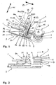
- a bending device 1 comprises a supporting structure 2 and a multi-level bending tool 3 mounted thereon.
- the bending device 1 is attached to the front end of a machine frame, not shown, of a bending machine.
- a workpiece feed carriage with collet can be moved.
- the collet holds the machine-side end of a workpiece to be machined, in the present case a tube 4.
- the tube 4 is positioned for processing.
- the multi-level bending tool 3, which is used to machine the tube 4 according to the unrolling stretch bending method, comprises bending molds 5, 6, 7 which are designed to have a total of three bending levels in the direction of a bending axis 8 are arranged one above the other.
- the bending molds 5, 6, 7 associated clamping jaws 9, 10, 11, which are also in the direction of the bending axis 8 above the other.
- Biegeformnuten 12, 13, 14 are clamping jaws 15, 16, 17 opposite.
- the Biegeformnuten 12, 13, 14 and the Spannbackennuten, 15, 16, 17 one and the same bending level have in the usual way a corresponding geometry.
- the bending-forming grooves 12, 13, 14 as well as the clamping-bar grooves 15, 16, 17 form in cross-section substantially circular receptacles for the workpieces to be machined.
- the illustrated example case arise due to a corresponding design of the Biegeformnuten 12, 13, 14 and the clamping jaw grooves 15, 16, 17 at the different bending levels slightly different diameter of the workpiece holders.
- the illustrated design conditions allow it accordingly, bending pipes with three different diameters bending.
- the multi-level bending tool 3 comprises in the direction of the bending axis 8 adjacent slide rails 18, 19, 20.
- Slide rail grooves 21, 22, 23 on the slide rails 18, 19, 20 are designed according to the clamping groove 15, 16, 17.
- the clamping jaws 9, 10, 11 are mounted on the side facing away from the bending forms 5, 6, 7 side on a jaw support in the form of a clamping bracket 24.
- the clamping block 24 with the clamping jaws 9, 10, 11 attached thereto is movable in the direction of a double arrow 25 and thus in the transverse direction of the bending axis 8.
- the clamping jaws 9, 10, 11 can be moved into a functional position close to the bending position or into a non-functional position away from bending.
- the movement of the clamping jaws 9, 10, 11 in the direction of the double arrow 25 is effected by means of a carriage 26, which is guided in the aforementioned direction of movement on a pivot arm 27 of the support structure 2.
- the required connection between the clamping jaws 9, 10, 11 and the carriage 26 is made via the clamping block 24.
- the clamping block 24 has a modular construction and, in the illustrated example, comprises clamping jaw support units 28, 29, 30 which are arranged one above the other in the direction of the bending axis 8 and braced against each other by means of a tie rod 31.
- the package of the jaw support units 28, 29, 30 produced by means of the tie rod 31 is attached to the carriage 26 via a fastening screw 32.
- the extension of the clamping jaw support unit 30 in the transverse direction of the bending axis 8 is three times the corresponding extent of the jaw support units 28, 29. In its extension in the longitudinal direction of the Pipe 4 and in their overall height in the direction of the bending axis 8, the jaw support units 28, 29, 30 coincide with each other.
- the jaw support units 28, 29 are structurally identical.
- On the jaw support unit 28, the jaw 9 is detachably attached. Accordingly, the jaw 10 on the jaw support unit 29 and the jaw 11 are attached to the jaw support unit 30.
- the Gleitschienen soin pulp 33, 33a are seen in the direction of the bending axis 8 on the Gleitschienen canin regulate 34, 34a, which in turn support the slide rail 19.
- the Gleitschienen retainer 34, 34a arranged concealed and therefore not visible.
- the Gleitschienen soin pulp 33, 34, 35 are held together by a tie rod 37, the Gleitschienen bisin pulp 33 a, 34 a, 35 a by a tie rod 38.
- the resulting packages of slide rail support units 33, 34, 35; 33a, 34a, 35a are attached by means of tie rods 37, 38 on the bends 36, 36a.
- the bends 36, 36 a are in turn attached to a longitudinal slide 39 of a cross slide 40.
- the longitudinal slide 39 is movably guided in the direction of a double arrow 41 and thus in the longitudinal direction of the pipe 4 to be machined on a cross slide 42 of the cross slide 40.
- the cross slide 42 in turn can be moved in the transverse direction of the tube 4 on a transverse guide 43 of the support structure 2 of the bending device 1.
- the slide rail support units 33, 33a, 34, 34a, 35, 35a collectively form a slide rail support 44, wherein the slide rail support units 33, 33a are associated with the upper, the slide rail support units 34, 34a the middle and the Gleitschienen basic 35, 35a the lower bending level of the Mehrleiveaubiegewerkmaschinemaschines 3.
- the bending tool parts of the upper bending level ie the bending mold 5, the clamping jaw 9 and the slide rail 18.
- the machining process itself runs in the usual way.
- the tube 4 is first adjusted in the tube longitudinal direction and in the tube circumferential direction.
- the Mehrpracticbiegewerkmaschine 3 is converted by appropriate relative movement relative to the machine frame of the bending machine in a position at the ingestion of the tube 4 can be processed by means of the tool parts of the upper bending level, when taking the tube 4 is received in the Biegeformnut 12 of the bending mold 5.
- the multi-level bending tool 3 is closed.
- the clamping block moves 24 with the attached jaws 9, 10, 11 in the transverse direction of the bending axis 8 to the bending molds 5, 6, 7 out.
- the tube 4 is now clamped between the bending mold 5 and the clamping jaw 9.
- the slide rail support 44 is transferred to the slide rails 18, 19, 20 in the transverse direction of the tube 4 in the workpiece-near functional position.
- the tube 4 comes to lie in the interior of the slide rail groove 21.
- the pivot arm 27 of the support structure 2 with the clamping jaws 9, 10, 11 mounted thereon is pivoted about the bending axis 8 in the direction of an arrow 45 shown in FIG.
- the deformed pipe section on the machine side adjacent pipe length is supported by means of the slide rail 18 in the workpiece transverse direction.
- the slide 18 follows the bending movement associated with the longitudinal movement of the tube 4. This movement of the slide rail 18 is effected by corresponding longitudinal movement of the longitudinal slide 39 on the cross slide 42nd
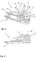
- Figs. 3 and 4 show the tube 4 when the bending device 1 is ready to process and immediately before the creation of a left bend. This was preceded by the creation of three bends, which ultimately led to the course of the tube 4 at the exiting from the multi-level bending tool 3 free end. So that the upcoming bend with the desired History of the bending plane can be created, the tube 4 was after the immediately preceding bend about its longitudinal axis in the from Figs. 3 and 4 apparent rotational position to move. This was only possible because the clamping bracket 24 and the slide rail support 44 had been suitably designed prior to the start of workpiece machining.
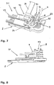
- FIGS. 5 to 8 show, as shown in FIGS. 1 to 4 a bending device 51.
- the bending device 51 differs from the bending device 1 according to FIGS. 1 to 4 by the design of a multi-level bending tool 53rd
- the multi-level bending tool 53 includes bending molds 55, 56, 57 that are reduced in diameter relative to the bending forms 5, 6, 7 of the multi-level bending tool 3 and thereby allow the creation of bends with a smaller bending radius.
- the bending forms 55, 56, 57 are assigned in accordance with the proportions shown in FIGS. 1 to 4 clamping jaws 9, 10, 11. Also used in the case of the bending device 51 slide rails 18, 19, 20 are consistent with the corresponding tool parts of Figs. 1 to 4 match.
- Consistency remains with regard to the design of the clamping bracket 24, which is composed of clamping jaw support units 28, 29, 30 also in the case of the bending device 51.
- the clamping block 24 is converted relative to the conditions in the case of the bending device 1 on the carriage 26 and thereby approximates the bending axis 8.
- the reduction in diameter of the bending molds 55, 56, 57 with respect to the bending molds 5, 6, 7 is thereby compensated.
- slide rail support 94 is designed in the case of the bending device 51.
- slide rail support 94 also includes slide rail support units 96, 96a. While the Gleitschienen Moinigan 33, 33 a, 34, 34 a structurally identical and, moreover, with the jaw support units 28, 29 of the clamping bracket 24 structurally coincide, have the Gleitschienen Moltens 96, 96a in the transverse direction of the machined, in Figs. 5, 6, for simplicity, not shown tube 4, the double extent of the jaw and slide support units 28, 29, 33, 33 a, 34, 34 a on.
- Figs. 1-8 shown jaw support units 28, 29, 30 as well as the slide rail support units 33, 33a, 34, 34a, 35, 35a, 96, 96a shown in the cited figures are all parts of a support unit construction kit, in the case of application related design of the clamping bracket 24 and the Slide rail supports 44, 94 is used. Included in this support unit kit are structurally categorized jaw and slide support units. With respect to the dimension in the transverse direction of the bending axis 8 and in the transverse direction of the pipe 4 to be processed, a total of three categories of support units are available. The largest extension category is the jaw support unit 30 of the medium extension category.
- the slide rail support units 96, 96a and the smallest extension category are the jaw support units 28, 29 and the slide rail support units 33, 33a, 34, 34a and 35, 35a assigned. Slide rail and jaw support units are interchangeable due to their structural conformity.
- the support unit construction kit comprises two categories. Alternatively to the in Figures 1 to 8 shown and the same height having support units are still support units with greater height available.
- the machine operator When setting up the relevant bending device, the machine operator can thus resort to a fund of support units, under which he has to make a choice depending on the requirements of the workpiece machining to be performed.
- the clamping jaws 9, 10, 11 and the slide rails 18, 19, 20 are to be attached to the selected support units.
- an adjustment of the clamping jaws 9, 10, 11 in the transverse direction of the bending axis 8 and / or an adjustment of the slide rails 18, 19, 20 in the transverse direction of the pipe to be machined 4 can also be made.
- the illustration of the existing setting options are shown in FIGS. 9, 10.
- clamping jaws 9, 10, 11 and the slide rails 18, 19, 20 are attached to the clamping jaw support units 28, 29, 30 and the slide rails 18, 19, 20 on the Gleitschienen Landing Agency 33, 33 a, 34, 34 a, 96, 96 a respectively by means of the clamping jaws 9, 10, 11 and the slide rails 18, 19, 20 provided with threaded bolts appropriate.
- the existing adjustment options can be used for fine adjustment on the individual bending levels, but can also be used for the appropriate positional change of the clamping jaws 9, 10, 11 and the slide rails 18, 19, 20 in the exchange of bending forms against bending shapes with different diameter or bending radius.
Landscapes
- Engineering & Computer Science (AREA)
- Mechanical Engineering (AREA)
- Bending Of Plates, Rods, And Pipes (AREA)
Priority Applications (4)
| Application Number | Priority Date | Filing Date | Title |
|---|---|---|---|
| EP03005461A EP1459816B1 (fr) | 2003-03-15 | 2003-03-15 | Dispostif de cintrage avec outil de cintrage à plusieurs niveaux, unité à machoires de serrage et unité de support à glissières pour un tel dispositif de cintrage |
| DE50304940T DE50304940D1 (de) | 2003-03-15 | 2003-03-15 | Biegeeinrichtung mit Mehrniveaubiegewerkzeug sowie Spannbacken-und Gleitschienenstützeinheit für eine derartige Biegeeinrichtung |
| ES03005461T ES2272828T3 (es) | 2003-03-15 | 2003-03-15 | Dispositivo de doblado con herramienta de doblado de varios niveles, una mordaza de sujecion y una unidad de soporte desplazable para dicho dispositivo de doblado. |
| US10/800,589 US7024903B2 (en) | 2003-03-15 | 2004-03-15 | Bending system with multilevel bending tool |
Applications Claiming Priority (1)
| Application Number | Priority Date | Filing Date | Title |
|---|---|---|---|
| EP03005461A EP1459816B1 (fr) | 2003-03-15 | 2003-03-15 | Dispostif de cintrage avec outil de cintrage à plusieurs niveaux, unité à machoires de serrage et unité de support à glissières pour un tel dispositif de cintrage |
Publications (2)
| Publication Number | Publication Date |
|---|---|
| EP1459816A1 true EP1459816A1 (fr) | 2004-09-22 |
| EP1459816B1 EP1459816B1 (fr) | 2006-09-06 |
Family
ID=32798809
Family Applications (1)
| Application Number | Title | Priority Date | Filing Date |
|---|---|---|---|
| EP03005461A Expired - Lifetime EP1459816B1 (fr) | 2003-03-15 | 2003-03-15 | Dispostif de cintrage avec outil de cintrage à plusieurs niveaux, unité à machoires de serrage et unité de support à glissières pour un tel dispositif de cintrage |
Country Status (4)
| Country | Link |
|---|---|
| US (1) | US7024903B2 (fr) |
| EP (1) | EP1459816B1 (fr) |
| DE (1) | DE50304940D1 (fr) |
| ES (1) | ES2272828T3 (fr) |
Cited By (8)
| Publication number | Priority date | Publication date | Assignee | Title |
|---|---|---|---|---|
| EP2223752A1 (fr) * | 2009-02-26 | 2010-09-01 | WAFIOS Aktiengesellschaft | Kit de construction des outils destinés à former des outils de cintrage pouvant être couplés sur une unité d'outils d'une machine de cintrage ou de l'enroulement de pièces en forme de tronçons |
| CN102151729A (zh) * | 2010-12-09 | 2011-08-17 | 中山市奥美森工业有限公司 | 长u弯管机的折弯装置的升降定位机构 |
| DE102008018736B4 (de) * | 2007-04-17 | 2011-12-22 | Gm Global Technology Operations Llc (N.D.Ges.D. Staates Delaware) | Schnellwechsel-Bogenwerkzeugbestückungs-Aufspannplatte |
| ITVI20120054A1 (it) * | 2012-03-15 | 2013-09-16 | Pedrazzoli Ibp Spa | Macchina piegatubi e metodo di piegatura impiegante tale macchina piegatubi |
| WO2014111638A1 (fr) | 2013-01-21 | 2014-07-24 | Eaton Leonard Europe | Dispositif de cintrage de profilés tels que des tubes |
| FR3007301A1 (fr) * | 2013-06-25 | 2014-12-26 | Financ Jaubert | Machine a cintrer un profile |
| CN103551430B (zh) * | 2013-10-29 | 2015-08-19 | 河南华电金源管道有限公司 | 冷弯管机主动轮变径加工方法及冷弯管机主动轮 |
| CN113351789A (zh) * | 2020-03-04 | 2021-09-07 | 广东联创建筑工程有限公司 | 一种建筑施工用钢筋折弯机 |
Families Citing this family (11)
| Publication number | Priority date | Publication date | Assignee | Title |
|---|---|---|---|---|
| US7254972B1 (en) * | 2006-06-28 | 2007-08-14 | Chia Sheng Machinery Co., Ltd. | Moving mold mechanism of a pipe bending machine |
| FR2922127B1 (fr) * | 2007-10-15 | 2010-03-05 | Jaubjaub Consulting | Machine a cintrer un profile et outillage de cintrage pour une telle machine |
| CN102139301B (zh) * | 2010-12-09 | 2013-01-02 | 中山市奥美森工业有限公司 | 长u弯管机 |
| CN102489562A (zh) * | 2011-12-24 | 2012-06-13 | 江阴中南重工股份有限公司 | 移动式热制弯管机 |
| CN102716954A (zh) * | 2012-06-28 | 2012-10-10 | 常熟市电力机具有限公司 | 弯管机的模具结构 |
| PL3027334T3 (pl) * | 2013-08-01 | 2018-07-31 | Addisonmckee, Inc. | Układ napinania drążka łączącego |
| US9482647B2 (en) * | 2013-09-24 | 2016-11-01 | Sikorsky Aircraft Corporation | Gear fault detection |
| EP3068556A4 (fr) | 2013-11-15 | 2018-02-14 | Textron Innovations Inc. | Fourniture de données pour fonctionnement de cintreuse automatisée |
| CN107913927B (zh) * | 2017-09-18 | 2024-05-03 | 浙江长兴和良智能装备有限公司 | 一种弯管机 |
| FR3099394B1 (fr) * | 2019-07-30 | 2021-07-09 | Numalliance | Dispositif de cintrage |
| CN112975421B (zh) * | 2021-02-18 | 2022-06-14 | 湖北皓润新材料科技有限公司 | 铜管成型设备 |
Citations (2)
| Publication number | Priority date | Publication date | Assignee | Title |
|---|---|---|---|---|
| GB2187666A (en) * | 1986-03-15 | 1987-09-16 | Pressbend Ltd | Pipe bending apparatus |
| DE19919508A1 (de) * | 1998-09-25 | 2000-03-30 | Pulzer Biegetechnik Gmbh | Gegenhaltevorrichtung für eine Biegemaschine |
Family Cites Families (5)
| Publication number | Priority date | Publication date | Assignee | Title |
|---|---|---|---|---|
| US4495788A (en) * | 1982-08-02 | 1985-01-29 | Eaton-Leonard Corporation | Multiple curvature bender |
| IT1251934B (it) * | 1991-10-16 | 1995-05-27 | Macchine Curvatubi Crippa Agos | Macchina curvatubi polifunzionale |
| DE19530805A1 (de) * | 1995-08-22 | 1997-02-27 | Schwarze Rigobert | CNC-gesteuerte Rohrbiegemaschine |
| US6038903A (en) * | 1998-03-09 | 2000-03-21 | Eaton Leonard, Inc. | Dual headed bending machine |
| US6655183B1 (en) * | 2002-07-16 | 2003-12-02 | Chiao Sheng Machinery Co., Ltd. | Lifting mechanism for a head member of a pipe bender |
-
2003
- 2003-03-15 EP EP03005461A patent/EP1459816B1/fr not_active Expired - Lifetime
- 2003-03-15 ES ES03005461T patent/ES2272828T3/es not_active Expired - Lifetime
- 2003-03-15 DE DE50304940T patent/DE50304940D1/de not_active Expired - Lifetime
-
2004
- 2004-03-15 US US10/800,589 patent/US7024903B2/en active Active
Patent Citations (2)
| Publication number | Priority date | Publication date | Assignee | Title |
|---|---|---|---|---|
| GB2187666A (en) * | 1986-03-15 | 1987-09-16 | Pressbend Ltd | Pipe bending apparatus |
| DE19919508A1 (de) * | 1998-09-25 | 2000-03-30 | Pulzer Biegetechnik Gmbh | Gegenhaltevorrichtung für eine Biegemaschine |
Cited By (14)
| Publication number | Priority date | Publication date | Assignee | Title |
|---|---|---|---|---|
| DE102008018736B4 (de) * | 2007-04-17 | 2011-12-22 | Gm Global Technology Operations Llc (N.D.Ges.D. Staates Delaware) | Schnellwechsel-Bogenwerkzeugbestückungs-Aufspannplatte |
| EP2223752A1 (fr) * | 2009-02-26 | 2010-09-01 | WAFIOS Aktiengesellschaft | Kit de construction des outils destinés à former des outils de cintrage pouvant être couplés sur une unité d'outils d'une machine de cintrage ou de l'enroulement de pièces en forme de tronçons |
| CN102151729A (zh) * | 2010-12-09 | 2011-08-17 | 中山市奥美森工业有限公司 | 长u弯管机的折弯装置的升降定位机构 |
| CN102151729B (zh) * | 2010-12-09 | 2013-05-01 | 中山市奥美森工业有限公司 | 长u弯管机的折弯装置的升降定位机构 |
| ITVI20120054A1 (it) * | 2012-03-15 | 2013-09-16 | Pedrazzoli Ibp Spa | Macchina piegatubi e metodo di piegatura impiegante tale macchina piegatubi |
| FR3001163A1 (fr) * | 2013-01-21 | 2014-07-25 | Eaton Leonard Europ | Dispositif de cintrage de profiles tels que des tubes |
| WO2014111638A1 (fr) | 2013-01-21 | 2014-07-24 | Eaton Leonard Europe | Dispositif de cintrage de profilés tels que des tubes |
| CN105592947A (zh) * | 2013-01-21 | 2016-05-18 | Admc控股有限责任公司 | 用于弯曲成型段如管的装置 |
| CN105592947B (zh) * | 2013-01-21 | 2018-01-26 | Admc控股有限责任公司 | 用于弯曲成型段如管的装置 |
| RU2655488C2 (ru) * | 2013-01-21 | 2018-05-28 | ЭйДиЭмСи ХОЛДИНГ, ЭлЭлСи | Устройство для гибки профилированных заготовок, таких как трубы |
| US10076779B2 (en) | 2013-01-21 | 2018-09-18 | Admc Holding, Llc | Device for bending profile sections such as tubes |
| FR3007301A1 (fr) * | 2013-06-25 | 2014-12-26 | Financ Jaubert | Machine a cintrer un profile |
| CN103551430B (zh) * | 2013-10-29 | 2015-08-19 | 河南华电金源管道有限公司 | 冷弯管机主动轮变径加工方法及冷弯管机主动轮 |
| CN113351789A (zh) * | 2020-03-04 | 2021-09-07 | 广东联创建筑工程有限公司 | 一种建筑施工用钢筋折弯机 |
Also Published As
| Publication number | Publication date |
|---|---|
| US20040200253A1 (en) | 2004-10-14 |
| ES2272828T3 (es) | 2007-05-01 |
| DE50304940D1 (de) | 2006-10-19 |
| US7024903B2 (en) | 2006-04-11 |
| EP1459816B1 (fr) | 2006-09-06 |
Similar Documents
| Publication | Publication Date | Title |
|---|---|---|
| EP1459816B1 (fr) | Dispostif de cintrage avec outil de cintrage à plusieurs niveaux, unité à machoires de serrage et unité de support à glissières pour un tel dispositif de cintrage | |
| EP1955789B1 (fr) | Cintreuse | |
| EP1700647B1 (fr) | Dispositif de cintrage pour les pièces en forme de tube et de barre et dispositif de lissage de pli | |
| EP0121077B1 (fr) | Machine à cintrer des tubes | |
| DE10050919B4 (de) | Verfahren zum Biegen von Metallrohren mit geringem Durchmesser und Vorrichtung hierfür | |
| WO1998008648A1 (fr) | Aleseuse et fraiseuse pour usiner des barres | |
| DE102010028032B4 (de) | Werkzeugmaschine mit zusätzlichem Zuganker | |
| EP3943239B1 (fr) | Machine-outil et procédé de fonctionnement de la machine-outil | |
| DE2918813A1 (de) | Vorrichtung zum biegen von metallstaeben | |
| DE2147436C3 (de) | Vorrichtung für Maschinen mit relativ zueinander bewegbaren Formhälften, insbesondere Druckgießmaschinen | |
| WO2019029893A1 (fr) | Machine à cintrer pour le cintrage de pièces en forme de tige ou de tube | |
| EP3302840B2 (fr) | Installation de fabrication pour la fabrication de pièces en tôle et procédé à cet effet | |
| EP1380362B1 (fr) | Machine de cintrage de tubes avec alimentation de tubes et recul de mandrin | |
| DE2813612B2 (de) | Vorrichtung zum Mittenkörnen der Stirnenden von Knuppern für die Herstellung nahtloser Rohre | |
| DE102009024406B4 (de) | Rotationsbiegewerkzeug mit Exzenterklemmung | |
| AT519221B1 (de) | Fertigungsanlage mit einem Klemmwerkzeug sowie Verfahren zur Anpassung einer Gesamtlänge einer Biegekante des Klemmwerkzeugs | |
| EP0623420B1 (fr) | Dispositif de transport et de fixation | |
| WO2004080627A1 (fr) | Machine plieuse destinee notamment a des tables de soudage ou de serrage, table de soudage et table de serrage | |
| EP2475474B1 (fr) | Machine de pliage pour plier des pièces allongées notamment des tubes ou des profilés | |
| EP1218124B1 (fr) | Dispositif de fa onnage d'elements longitudinaux | |
| EP0364836A2 (fr) | Procédé et dispositif pour cintrer des pièces à usiner en barres | |
| DE102018128903A1 (de) | Vorrichtung zum Biegen stabförmiger Werkstücke | |
| DE102004015073B3 (de) | Vorrichtung und Verfahren zum Biegen eines Werkstücks | |
| DE10334166B3 (de) | Zuführeinrichtung | |
| EP2308611B1 (fr) | Dispositif pour le cintrage d'éléments allongés |
Legal Events
| Date | Code | Title | Description |
|---|---|---|---|
| PUAI | Public reference made under article 153(3) epc to a published international application that has entered the european phase |
Free format text: ORIGINAL CODE: 0009012 |
|
| AK | Designated contracting states |
Kind code of ref document: A1 Designated state(s): AT BE BG CH CY CZ DE DK EE ES FI FR GB GR HU IE IT LI LU MC NL PT RO SE SI SK TR |
|
| AX | Request for extension of the european patent |
Extension state: AL LT LV MK |
|
| 17P | Request for examination filed |
Effective date: 20050306 |
|
| AKX | Designation fees paid |
Designated state(s): CH DE ES FR GB IT LI |
|
| GRAP | Despatch of communication of intention to grant a patent |
Free format text: ORIGINAL CODE: EPIDOSNIGR1 |
|
| GRAS | Grant fee paid |
Free format text: ORIGINAL CODE: EPIDOSNIGR3 |
|
| GRAA | (expected) grant |
Free format text: ORIGINAL CODE: 0009210 |
|
| RAP1 | Party data changed (applicant data changed or rights of an application transferred) |
Owner name: TRUMPF WERKZEUGMASCHINEN GMBH + CO. KG |
|
| AK | Designated contracting states |
Kind code of ref document: B1 Designated state(s): CH DE ES FR GB IT LI |
|
| PG25 | Lapsed in a contracting state [announced via postgrant information from national office to epo] |
Ref country code: IT Free format text: LAPSE BECAUSE OF FAILURE TO SUBMIT A TRANSLATION OF THE DESCRIPTION OR TO PAY THE FEE WITHIN THE PRESCRIBED TIME-LIMIT;WARNING: LAPSES OF ITALIAN PATENTS WITH EFFECTIVE DATE BEFORE 2007 MAY HAVE OCCURRED AT ANY TIME BEFORE 2007. THE CORRECT EFFECTIVE DATE MAY BE DIFFERENT FROM THE ONE RECORDED. Effective date: 20060906 |
|
| REG | Reference to a national code |
Ref country code: GB Ref legal event code: FG4D Free format text: NOT ENGLISH |
|
| REG | Reference to a national code |
Ref country code: CH Ref legal event code: EP |
|
| REF | Corresponds to: |
Ref document number: 50304940 Country of ref document: DE Date of ref document: 20061019 Kind code of ref document: P |
|
| GBT | Gb: translation of ep patent filed (gb section 77(6)(a)/1977) |
Effective date: 20070108 |
|
| ET | Fr: translation filed | ||
| REG | Reference to a national code |
Ref country code: ES Ref legal event code: FG2A Ref document number: 2272828 Country of ref document: ES Kind code of ref document: T3 |
|
| PLBE | No opposition filed within time limit |
Free format text: ORIGINAL CODE: 0009261 |
|
| STAA | Information on the status of an ep patent application or granted ep patent |
Free format text: STATUS: NO OPPOSITION FILED WITHIN TIME LIMIT |
|
| 26N | No opposition filed |
Effective date: 20070607 |
|
| PGFP | Annual fee paid to national office [announced via postgrant information from national office to epo] |
Ref country code: CH Payment date: 20080304 Year of fee payment: 6 Ref country code: ES Payment date: 20080326 Year of fee payment: 6 |
|
| PGFP | Annual fee paid to national office [announced via postgrant information from national office to epo] |
Ref country code: GB Payment date: 20080307 Year of fee payment: 6 |
|
| PGFP | Annual fee paid to national office [announced via postgrant information from national office to epo] |
Ref country code: FR Payment date: 20080228 Year of fee payment: 6 |
|
| REG | Reference to a national code |
Ref country code: CH Ref legal event code: PL |
|
| GBPC | Gb: european patent ceased through non-payment of renewal fee |
Effective date: 20090315 |
|
| REG | Reference to a national code |
Ref country code: FR Ref legal event code: ST Effective date: 20091130 |
|
| PG25 | Lapsed in a contracting state [announced via postgrant information from national office to epo] |
Ref country code: CH Free format text: LAPSE BECAUSE OF NON-PAYMENT OF DUE FEES Effective date: 20090331 Ref country code: LI Free format text: LAPSE BECAUSE OF NON-PAYMENT OF DUE FEES Effective date: 20090331 |
|
| PG25 | Lapsed in a contracting state [announced via postgrant information from national office to epo] |
Ref country code: FR Free format text: LAPSE BECAUSE OF NON-PAYMENT OF DUE FEES Effective date: 20091123 Ref country code: GB Free format text: LAPSE BECAUSE OF NON-PAYMENT OF DUE FEES Effective date: 20090315 |
|
| REG | Reference to a national code |
Ref country code: ES Ref legal event code: FD2A Effective date: 20090316 |
|
| PG25 | Lapsed in a contracting state [announced via postgrant information from national office to epo] |
Ref country code: ES Free format text: LAPSE BECAUSE OF NON-PAYMENT OF DUE FEES Effective date: 20090316 |
|
| PGFP | Annual fee paid to national office [announced via postgrant information from national office to epo] |
Ref country code: IT Payment date: 20210329 Year of fee payment: 19 |
|
| PGFP | Annual fee paid to national office [announced via postgrant information from national office to epo] |
Ref country code: DE Payment date: 20210319 Year of fee payment: 19 |
|
| REG | Reference to a national code |
Ref country code: DE Ref legal event code: R119 Ref document number: 50304940 Country of ref document: DE |
|
| PG25 | Lapsed in a contracting state [announced via postgrant information from national office to epo] |
Ref country code: DE Free format text: LAPSE BECAUSE OF NON-PAYMENT OF DUE FEES Effective date: 20221001 |
|
| PG25 | Lapsed in a contracting state [announced via postgrant information from national office to epo] |
Ref country code: IT Free format text: LAPSE BECAUSE OF NON-PAYMENT OF DUE FEES Effective date: 20220315 |