EP1458653B1 - Anti-reflektions schichtsystem auf einem glassubsrat mit hoher transmission für sichtbares licht und geringer emissionsfähigkeit - Google Patents
Anti-reflektions schichtsystem auf einem glassubsrat mit hoher transmission für sichtbares licht und geringer emissionsfähigkeit Download PDFInfo
- Publication number
- EP1458653B1 EP1458653B1 EP02797326.2A EP02797326A EP1458653B1 EP 1458653 B1 EP1458653 B1 EP 1458653B1 EP 02797326 A EP02797326 A EP 02797326A EP 1458653 B1 EP1458653 B1 EP 1458653B1
- Authority
- EP
- European Patent Office
- Prior art keywords
- layer
- refraction
- coated article
- dielectric
- dielectric portion
- Prior art date
- Legal status (The legal status is an assumption and is not a legal conclusion. Google has not performed a legal analysis and makes no representation as to the accuracy of the status listed.)
- Expired - Fee Related
Links
Images


Classifications
-
- C—CHEMISTRY; METALLURGY
- C03—GLASS; MINERAL OR SLAG WOOL
- C03C—CHEMICAL COMPOSITION OF GLASSES, GLAZES OR VITREOUS ENAMELS; SURFACE TREATMENT OF GLASS; SURFACE TREATMENT OF FIBRES OR FILAMENTS MADE FROM GLASS, MINERALS OR SLAGS; JOINING GLASS TO GLASS OR OTHER MATERIALS
- C03C17/00—Surface treatment of glass, not in the form of fibres or filaments, by coating
- C03C17/34—Surface treatment of glass, not in the form of fibres or filaments, by coating with at least two coatings having different compositions
- C03C17/36—Surface treatment of glass, not in the form of fibres or filaments, by coating with at least two coatings having different compositions at least one coating being a metal
- C03C17/3602—Surface treatment of glass, not in the form of fibres or filaments, by coating with at least two coatings having different compositions at least one coating being a metal the metal being present as a layer
- C03C17/3618—Coatings of type glass/inorganic compound/other inorganic layers, at least one layer being metallic
-
- C—CHEMISTRY; METALLURGY
- C03—GLASS; MINERAL OR SLAG WOOL
- C03C—CHEMICAL COMPOSITION OF GLASSES, GLAZES OR VITREOUS ENAMELS; SURFACE TREATMENT OF GLASS; SURFACE TREATMENT OF FIBRES OR FILAMENTS MADE FROM GLASS, MINERALS OR SLAGS; JOINING GLASS TO GLASS OR OTHER MATERIALS
- C03C17/00—Surface treatment of glass, not in the form of fibres or filaments, by coating
- C03C17/34—Surface treatment of glass, not in the form of fibres or filaments, by coating with at least two coatings having different compositions
- C03C17/36—Surface treatment of glass, not in the form of fibres or filaments, by coating with at least two coatings having different compositions at least one coating being a metal
- C03C17/3602—Surface treatment of glass, not in the form of fibres or filaments, by coating with at least two coatings having different compositions at least one coating being a metal the metal being present as a layer
- C03C17/3626—Surface treatment of glass, not in the form of fibres or filaments, by coating with at least two coatings having different compositions at least one coating being a metal the metal being present as a layer one layer at least containing a nitride, oxynitride, boronitride or carbonitride
-
- C—CHEMISTRY; METALLURGY
- C03—GLASS; MINERAL OR SLAG WOOL
- C03C—CHEMICAL COMPOSITION OF GLASSES, GLAZES OR VITREOUS ENAMELS; SURFACE TREATMENT OF GLASS; SURFACE TREATMENT OF FIBRES OR FILAMENTS MADE FROM GLASS, MINERALS OR SLAGS; JOINING GLASS TO GLASS OR OTHER MATERIALS
- C03C17/00—Surface treatment of glass, not in the form of fibres or filaments, by coating
- C03C17/34—Surface treatment of glass, not in the form of fibres or filaments, by coating with at least two coatings having different compositions
- C03C17/36—Surface treatment of glass, not in the form of fibres or filaments, by coating with at least two coatings having different compositions at least one coating being a metal
- C03C17/3602—Surface treatment of glass, not in the form of fibres or filaments, by coating with at least two coatings having different compositions at least one coating being a metal the metal being present as a layer
- C03C17/3639—Multilayers containing at least two functional metal layers
-
- C—CHEMISTRY; METALLURGY
- C03—GLASS; MINERAL OR SLAG WOOL
- C03C—CHEMICAL COMPOSITION OF GLASSES, GLAZES OR VITREOUS ENAMELS; SURFACE TREATMENT OF GLASS; SURFACE TREATMENT OF FIBRES OR FILAMENTS MADE FROM GLASS, MINERALS OR SLAGS; JOINING GLASS TO GLASS OR OTHER MATERIALS
- C03C17/00—Surface treatment of glass, not in the form of fibres or filaments, by coating
- C03C17/34—Surface treatment of glass, not in the form of fibres or filaments, by coating with at least two coatings having different compositions
- C03C17/36—Surface treatment of glass, not in the form of fibres or filaments, by coating with at least two coatings having different compositions at least one coating being a metal
- C03C17/3602—Surface treatment of glass, not in the form of fibres or filaments, by coating with at least two coatings having different compositions at least one coating being a metal the metal being present as a layer
- C03C17/3644—Surface treatment of glass, not in the form of fibres or filaments, by coating with at least two coatings having different compositions at least one coating being a metal the metal being present as a layer the metal being silver
-
- C—CHEMISTRY; METALLURGY
- C03—GLASS; MINERAL OR SLAG WOOL
- C03C—CHEMICAL COMPOSITION OF GLASSES, GLAZES OR VITREOUS ENAMELS; SURFACE TREATMENT OF GLASS; SURFACE TREATMENT OF FIBRES OR FILAMENTS MADE FROM GLASS, MINERALS OR SLAGS; JOINING GLASS TO GLASS OR OTHER MATERIALS
- C03C17/00—Surface treatment of glass, not in the form of fibres or filaments, by coating
- C03C17/34—Surface treatment of glass, not in the form of fibres or filaments, by coating with at least two coatings having different compositions
- C03C17/36—Surface treatment of glass, not in the form of fibres or filaments, by coating with at least two coatings having different compositions at least one coating being a metal
- C03C17/3602—Surface treatment of glass, not in the form of fibres or filaments, by coating with at least two coatings having different compositions at least one coating being a metal the metal being present as a layer
- C03C17/3652—Surface treatment of glass, not in the form of fibres or filaments, by coating with at least two coatings having different compositions at least one coating being a metal the metal being present as a layer the coating stack containing at least one sacrificial layer to protect the metal from oxidation
-
- C—CHEMISTRY; METALLURGY
- C03—GLASS; MINERAL OR SLAG WOOL
- C03C—CHEMICAL COMPOSITION OF GLASSES, GLAZES OR VITREOUS ENAMELS; SURFACE TREATMENT OF GLASS; SURFACE TREATMENT OF FIBRES OR FILAMENTS MADE FROM GLASS, MINERALS OR SLAGS; JOINING GLASS TO GLASS OR OTHER MATERIALS
- C03C17/00—Surface treatment of glass, not in the form of fibres or filaments, by coating
- C03C17/34—Surface treatment of glass, not in the form of fibres or filaments, by coating with at least two coatings having different compositions
- C03C17/36—Surface treatment of glass, not in the form of fibres or filaments, by coating with at least two coatings having different compositions at least one coating being a metal
- C03C17/3602—Surface treatment of glass, not in the form of fibres or filaments, by coating with at least two coatings having different compositions at least one coating being a metal the metal being present as a layer
- C03C17/3657—Surface treatment of glass, not in the form of fibres or filaments, by coating with at least two coatings having different compositions at least one coating being a metal the metal being present as a layer the multilayer coating having optical properties
- C03C17/366—Low-emissivity or solar control coatings
-
- C—CHEMISTRY; METALLURGY
- C03—GLASS; MINERAL OR SLAG WOOL
- C03C—CHEMICAL COMPOSITION OF GLASSES, GLAZES OR VITREOUS ENAMELS; SURFACE TREATMENT OF GLASS; SURFACE TREATMENT OF FIBRES OR FILAMENTS MADE FROM GLASS, MINERALS OR SLAGS; JOINING GLASS TO GLASS OR OTHER MATERIALS
- C03C2217/00—Coatings on glass
- C03C2217/70—Properties of coatings
- C03C2217/73—Anti-reflective coatings with specific characteristics
- C03C2217/734—Anti-reflective coatings with specific characteristics comprising an alternation of high and low refractive indexes
Definitions
- the 09/794,224 application discloses coated articles having the following layer stack, as shown in Figure 1 herein, from the glass substrate outwardly: Table 1: Example Materials/Thicknesses Layer Preferred Range ( ⁇ ) More Preferred ( ⁇ ) Example ( ⁇ ) Substrate (1-10 mm) TiO 2 0-400 ⁇ 50-250 ⁇ 100 ⁇ Si x N y 0-400 ⁇ 50-250 ⁇ 170 ⁇ NiCrO x 5-100 ⁇ 10-50 ⁇ 18 ⁇ Ag 50-250 ⁇ 80-120 ⁇ 105 ⁇ NiCrO x 5-100 ⁇ 10-50 ⁇ 16 ⁇ SnO 2 0-800 ⁇ 500-850 ⁇ 650 ⁇ Si x N y 0-800 ⁇ 50-250 ⁇ 170 ⁇ NiCrO x 5-100 ⁇ 10-50 ⁇ 18 ⁇ Ag 50-250 ⁇ 80-120 ⁇ 105 ⁇ NiCrO x 5-100 ⁇ 10-50 ⁇ 16 ⁇ SnO 2 0-500 ⁇ 100-300
- the bottom titanium oxide layer may be removed or replaced with a silicon nitride layer.
- US 6,306,525 B1 suggests a thin multilayer coating having reflection properties in the infrared and/or in the solar radiation range of the low-emissivity type for windows.
- the coating comprises a lower dielectric antireflection treatment layer, at least one silver-based functional layer, at least one metallic protection layer adjacent to the silver layer and an upper dielectric antireflection treatment layer.
- a solar controlling coated article i.e., an article including at least one and preferably two or more layers such as Ag and/or Au for reflecting IR and/or UV
- a solar controlling coated article having increased visible transmission and/or reduced visible reflectance
- an improved anti-reflection layer(s) system(s) may enable coatings to have or utilize more robust contact layer(s) (e.g., thicker for better durability) and/or thicker silver (Ag) layer(s) (i.e., improved thermal performance) while maintaining similar transmission characteristics if increased transmission is not a most desired feature (e.g., if durability is a most desired feature).
- Another object of this invention is to fulfill one or more of the above-listed objects and/or needs.
- the instant invention relates to coated articles which may be used in applications including but not limited to insulating glass (IG) window units, monolithic windows, skylight windows, and/or any other type of window.
- Coated articles according to this invention include an improved anti-reflection layer(s) system for reducing visible reflectance and/or increasing visible transmission in coated articles that provide solar control (e.g., IR and/or UV reflection) functionality.
- solar control e.g., IR and/or UV reflection
- certain anti-reflection layer(s) systems of the instant invention can both: (a) improve visible transmission and/or reduce visible reflectance, while at the same time (b) achieving an acceptable neutral color of the resulting coated article.
- Fig. 2 is a cross sectional view of a coated article according to an embodiment of this invention.
- the coated article of Fig. 2 may be used in any of the aforesaid applications (e.g., architectural windows, etc.).
- the coated article of Fig. 2 includes from the glass substrate outwardly (all indices of refraction "n" at 550 nm):
- the contact layers i.e., NiCrO x layers
- the NiCrO x layers herein are called "contact” layers because they each contact an IR reflecting layer (i.e., an Ag layer).
- the NiCrO x contact layers provide the most immediate chemical protection for the Ag layer, and also serve as adhesion and/or nucleation layers.
- the contact layers may or may not be oxidation graded as described in the 09/794,224 application, in different embodiments of this invention.
- one or more of the contact layers may be of or include other material(s) including but not limited to NiCr, NiCrN x , NiCrO x N y , ZnO, Al 2 O 3 , TiO 2 , ZnAlO x , Ni, Cr, CrN x , NiO x , NbO x , any combination thereof, and/or the like.
- materials such as titanium oxide or niobium oxide could even serve as top contact layers (i.e., above Ag layer(s)), in addition to dielectrics herein.
- Example thicknesses of the contact layers, and other layers herein, are discussed above in the Background and Summary section of this application. The above applies to contact layers in the Fig. 1-17 embodiments.
- metallic IR reflecting materials e.g., Au, Ag alloys, Au alloys, etc.
- the thickness of the metallic Ag layers (IR reflecting layers) is chosen in order to achieve the desired thermal performance (see example thickness ranges above).
- the Ag layer may be from about 50-250 ⁇ thick, in order to achieve sheet resistance (R s ) (before and/or after heat treatment) of less than or equal to 10.0 ohms/square, more preferably less than or equal to 8.0 ohms/square, even more preferably less than or equal to 5.0 ohms/square, and most preferably less than or equal to 4.0 ohms/square.
- the Ag layer(s) thickness(es) are chosen so that the coating (or coated article) has a normal emissivity (E n ) of no greater than 0.08, more preferably no greater than 0.06, and most preferably no greater than 0.05 (before and/or after heat treatment).
- E n normal emissivity
- the aforesaid emissivity and sheet resistance characteristics apply to the Fig. 1-17 embodiments.
- the IR reflecting and contact layers of the Fig. 2 coating are discussed in the 09/794,224 application, and are not discussed herein for reasons of simplicity. See the thicknesses/materials described in the 09/794,224 in this regard.
- the focus herein lies with the provision of dielectric layers which are utilized in order to: (a) increase visible transmission, (b) decrease visible reflection (e.g., glass side), and/or (c) provide neutral color.
- the dielectric layers used therein result in a significant increase in visible transmission combined with a decrease in visible reflectance (glass and/or film side). This is beneficial.
- the Fig. 2 embodiment of this invention differs from Fig. 1 in that (a) the bottom silicon nitride layer from Fig. 1 has been removed, (b) a titanium oxide layer has been added in the middle portion M, (c) the middle silicon nitride layer from Fig. 1 has been removed, (d) titanium oxide and silicon oxide layers have been added to the top portion T of the coating in Fig. 2 , and (e) the top silicon nitride layer from Fig. 1 has been removed.
- the coating can be characterized by the top dielectric portion T having an effective index of refraction n less than that of middle dielectric portion M, which in turn has an effective index of refraction n less than that of the bottom dielectric portion B (see Fig. 2 ).
- each of the top, middle and bottom dielectric portions T, M and B can include a plurality of different dielectric layers, although in alternative embodiments any or all of these portions need only include a single dielectric layer.
- the silicon oxide layers herein may be from about 10-700 ⁇ thick in certain example embodiments of this invention, more preferably from 20-600 ⁇ thick, and most preferably from 50-500 ⁇ thick.
- Upper tin oxide layers herein may be from about 10-700 ⁇ thick in certain example embodiments of this invention, more preferably from 20-600 ⁇ thick, and most preferably from 40-400 ⁇ thick.
- Upper titanium oxide layers herein i.e., in top portion T above the top IR reflecting layer
- Middle titanium oxide layers herein i.e., in middle portion M between the IR reflecting layers
- Bottom titanium oxide layers herein may have thicknesses as discussed in 09/794,224 .
- the illustrated layers are preferably deposited/formed via sputtering (see the Examples in the 09/794,224 application), although other deposition techniques may certainly be used in alternative embodiments of this invention.
- Example 1 of the Fig. 2 embodiment which are to be compared to a Comparative Example(s) (CE) similar to Fig. 1 of the instant application.
- CE Comparative Example(s)
- the CE relates to a coating that is similar to that illustrated in the 09/794,224 application.
- the thicknesses for each of the layers in the First Table below are in angstroms ( ⁇ ).
- the Second Table below sets forth the optical characteristics (e.g., visible transmission, color, etc.) for the Example(s) and CE based upon being annealed and in monolithic form. All glass substrates were the same with respect to thickness and color. The total dielectric parameter simply adds up the total thickness of all dielectric layers in the coating (i.e., does not include Ag or NiCrO x layers).
- the anti-reflection system of the instant invention enables not only better visible transmission characteristics (i.e., increased transmission T vis %, Ill. C, 2 deg.), but also reduced reflection (e.g., lower glass side reflection and/or film side reflection). Moreover, fairly neutral transmissive color is also provided. Surprisingly, it can be seen that the Fig. 2 embodiment provides more neutral color (e.g., transmissive a* and glass side reflective) than does the CE. In particular, Example 1 (see Fig.
- Figure 3 is a cross sectional view of a coated article according to a comparative example.
- the Fig. 3 embodiment differs from the Fig. 2 embodiment in that the top dielectric portion T includes only a silicon nitride layer (stoichiometric Si 3 N 4 , or alternative a non-stoichiometric type of silicon nitride such as but not limited to a Si-rich type).
- the Fig. 3 embodiment differs from Fig. 1 (i.e., from the CE) in that (a) the bottom silicon nitride layer from Fig. 1 has been removed, (b) a titanium oxide layer has been added in the middle portion M, (c) the middle silicon nitride layer from Fig.
- the coated article of Fig. 3 includes from the glass substrate outwardly (all indices n at 550 nm):
- the layer system can be characterized by the top dielectric portion T having an effective index of refraction n less than that of middle dielectric portion M, which in turn has an effective index of refraction n less than that of the bottom dielectric portion B.
- n T is the effective index of refraction of the top dielectric portion T (i.e., of the silicon nitride layer in this embodiment)
- n M is the effective index of refraction of the middle dielectric portion M (i.e., of the tin oxide and titanium oxide layers in this embodiment)
- n B is the effective index of refraction of the bottom dielectric portion B (i.e., of the titanium oxide layer in this embodiment).
- Each of the top, middle and bottom dielectric portions T, M and B, respectively can include a plurality of different dielectric layers, although in alternative embodiments any or all of these portions need only include a single dielectric layer (e.g. portions B and T in this Fig.
- the anti-reflection system of Fig. 3 enables increased visible transmission to be achieved.
- the term "effective" means the overall effective index n in a particular portion B, T or M, regardless of how many dielectric layers are provided therein.
- the anti-reflection system may also enable fairly neutral color of the coated article in certain example embodiments.
- the silicon nitride layer in portion T may be from about 10-900 ⁇ thick in certain example embodiments, more preferably from 20-600 ⁇ thick, and most preferably from 50-500 ⁇ thick.
- Example 1 of the Fig. 3 embodiment compared to a Comparative Example(s) (CE) similar to Fig. 1 of the instant application.
- CE Comparative Example(s)
- the thicknesses for each of the layers in the First Table below are in angstroms ( ⁇ ).
- the Second Table below sets forth the optical characteristics (e.g., visible transmission, color, etc.) for Example 1 and the CE based upon being annealed and in monolithic form.
- the anti-reflection system enables not only better visible transmission characteristics (i.e., increased visible transmission T vis %), but also reduced reflection (e.g., lower glass side reflection and/or film side visible reflection).
- Example 1 had better visible transmission (higher T vis ) and better glass and/or film side reflection (lower R g and/or R f ) than the Comparative Example (CE - see Fig. 1 ).
- the Example 1 of this embodiment also had more neutral color than the CE with respect to transmissive a*, and particularly with respect to glass side reflective a*, b*.
- Figure 4 is a cross sectional view of a coated article according to another embodiment of this invention.
- the Fig. 4 embodiment differs from the Fig. 2 embodiment in that an additional silicon nitride layer has been added in the bottom dielectric portion B between the lower contact layer and the titanium oxide layer.
- the term "between” as used herein to state that a layer(s) is "between" layers x and y does not mean that the layer(s) contacts layer x or layer y; it merely means that the layer(s) is between the layers x and y regardless of whether other layer(s) are also between layers x and y.
- the coated article of Fig. 4 includes from the glass substrate outwardly (all indices n at 550 nm):
- the layer system can be characterized by the top dielectric portion T having an effective index of refraction n less than that of middle dielectric portion M, which in turn has an effective index of refraction n less than that of the bottom dielectric portion B.
- n T ⁇ n M ⁇ n B where n T is the effective index of refraction of the top dielectric portion T, n M is the effective index of refraction of the middle dielectric portion M, and n B is the effective index of refraction of the bottom dielectric portion B.
- Each of the top, middle and bottom dielectric portions T, M and B, respectively, can include a plurality of different dielectric layers, although in alternative embodiments any or all of these portions need only include a single dielectric layer.
- the anti-reflection system of this embodiment enables increased visible transmission to be achieved.
- the anti-reflection system may also enable fairly neutral color of the coated article in certain example embodiments.
- the Tables below illustrate Examples 1-4 of the Fig. 4 embodiment, compared to a Comparative Example(s) (CE) similar to Fig. 1 of the instant application.
- the CE relates to a coating that is similar to that illustrated in the 09/794,224 application.
- the thicknesses for each of the layers in the First Table below are in angstroms ( ⁇ ).
- the Second Table below sets forth the optical characteristics (e.g., visible transmission, color, etc.) for Examples 1-4 and the CE based upon being annealed and in monolithic form.
- FIRST TABLE: LAYER STRUCTURE - thicknesses (Fig. 4 embodiment) CE Ex. 1 Ex. 2 Ex. 3 Ex.
- the anti-reflection system of the instant invention enables not only better visible transmission characteristics (i.e., increased visible transmission T vis %), but also reduced reflection (e.g., lower glass side reflection and/or film side visible reflection).
- Examples 1-4 see Fig. 4
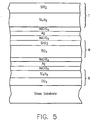
- Figure 5 is a cross sectional view of a coated article according to another embodiment of this invention.
- the Fig. 5 embodiment differs from the Fig. 3 embodiment in that an additional silicon nitride layer has been added in the bottom dielectric portion B between the lower contact layer and the titanium oxide layer, and a silicon oxide layer has been added over the silicon nitride layer in the top dielectric portion T.
- the coated article of Fig. 5 includes from the glass substrate outwardly (all indices n at 550 nm):
- the layer system can be characterized by the top dielectric portion T having an effective index of refraction n less than that of middle dielectric portion M, which in turn has an effective index of refraction n less than or equal to that of the bottom dielectric portion B.
- Each of the top, middle and bottom dielectric portions T, M and B, respectively, can include a plurality of different dielectric layers, although in alternative embodiments any or all of these portions need only include a single dielectric layer.
- the anti-reflection system of this embodiment enables increased visible transmission to be achieved.
- the anti-reflection system may also enable fairly neutral color of the coated article in certain example embodiments.
- Example 1 of the Fig. 5 embodiment compared to a Comparative Example(s) (CE) similar to Fig. 1 of the instant application.
- the CE relates to a coating that is similar to that illustrated in the 09/794,224 application.
- the thicknesses for each of the layers in the First Table below are in angstroms ( ⁇ ).
- the Second Table below sets forth the optical characteristics (e.g., visible transmission, color, etc.) for Example 1 and the CE based upon being annealed and in monolithic form.
- Example 1 had better visible transmission (higher T vis ) and better glass and/or film side reflection (lower R g and/or R f ) than the Comparative Example (CE - see Fig. 1 ). Surprisingly, Example 1 also had more neutral transmissive and glass side reflective color than the CE.
- Figure 6 is a cross sectional view of a coated article according to another embodiment of this invention.
- the Fig. 6 embodiment differs from the Fig. 2 embodiment in that the upper tin oxide layer in the portion T has been removed from the Fig. 2 embodiment and an additional silicon nitride layer has been added in the bottom dielectric portion B between the lower contact layer and the titanium oxide layer.
- the coated article of Fig. 6 includes from the glass substrate outwardly (all indices n at 550 nm):
- the layer system can be characterized by the top dielectric portion T having an effective index of refraction n less than that of middle dielectric portion M, which in turn has an effective index of refraction n less than or equal to that of the bottom dielectric portion B.
- Each of the top, middle and bottom dielectric portions T, M and B, respectively, can include a plurality of different dielectric layers, although in alternative embodiments any or all of these portions need only include a single dielectric layer.
- the anti-reflection system of this embodiment enables increased visible transmission to be achieved.
- the anti-reflection system may also enable fairly neutral color of the coated article in certain example embodiments.
- Example 1 of the Fig. 6 embodiment compared to a Comparative Example(s) (CE) similar to Fig. 1 of the instant application.
- the CE relates to a coating that is similar to that illustrated in the 09/794,224 application.
- the thicknesses for each of the layers in the First Table below are in angstroms ( ⁇ ).
- the Second Table below sets forth the optical characteristics (e.g., visible transmission, color, etc.) for Example 1 and the CE based upon being annealed and in monolithic form.
- Example 1 had better visible transmission (higher T vis ) and better glass and/or film side reflection (lower R g and/or R f ) than the Comparative Example (CE - see Fig. 1 ). Surprisingly, Example 1 also had more neutral transmissive and glass side reflective color than the CE.
- Figure 7 is a cross sectional view of a coated article according to another embodiment of this invention.
- the Fig. 7 embodiment differs from the Fig. 2 embodiment in that the upper titanium oxide layer from the Fig. 2 embodiment in portion T has been removed, and an additional silicon nitride layer has been added in Fig. 7 in the bottom dielectric portion B between the lower contact layer and the titanium oxide layer.
- the coated article of Fig. 7 includes from the glass substrate outwardly (all indices n at 550 nm):
- the layer system can be characterized by the top dielectric portion T having an effective index of refraction n less than that of middle dielectric portion M, which in turn has an effective index of refraction n less than or equal to that of the bottom dielectric portion B.
- Each of the top, middle and bottom dielectric portions T, M and B, respectively, can include a plurality of different dielectric layers, although in alternative embodiments any or all of these portions need only include a single dielectric layer.
- the anti-reflection system of this embodiment enables increased visible transmission to be achieved.
- the anti-reflection system may also enable fairly neutral color of the coated article in certain example embodiments.
- Example 1 of the Fig. 7 embodiment compared to a Comparative Example(s) (CE) similar to Fig. 1 of the instant application.
- the CE relates to a coating that is similar to that illustrated in the 09/794,224 application.
- the thicknesses for each of the layers in the First Table below are in angstroms ( ⁇ ).
- the Second Table below sets forth the optical characteristics (e.g., visible transmission, color, etc.) for Example 1 and the CE based upon being annealed and in monolithic form.
- Example 1 had better visible transmission (higher T vis ) and better glass and/or film side reflection (lower R g and/or R f ) than the Comparative Example (CE - see Fig. 1 ). Surprisingly, Example 1 also had fairly neutral color.
- Figure 8 is a cross sectional view of a coated article according to another embodiment of this invention.
- the Fig. 8 embodiment differs from the Fig. 4 embodiment in that the upper dielectric portion in the Fig. 8 embodiment includes a silicon oxynitride layer.
- the silicon oxynitride layer is beneficial in that its index of refraction n (at 550 nm) can be varied from 1.45 to 2.0, more preferably from 1.6 to 1.9, and most preferably from 1.65 to 1.85, in different embodiments of this invention.
- the silicon oxynitride layer may have a constant (or approximately constant, i.e., constant plus/minus about 5%) index of refraction n throughout its entire thickness in certain embodiments of this invention, but alternatively may be oxidation and/or nitride graded so as to have an index of refraction n which varies through the thickness of the layer (e.g., the index n may gradually decrease through the thickness of the silicon oxynitride layer moving toward the air).
- the coated article of Fig. 8 includes from the glass substrate outwardly (all indices n at 550 nm):
- n effective index of refraction n
- n T ⁇ n M ⁇ n B , where n T is the effective index of refraction of the top dielectric portion T, n M is the effective index of refraction of the middle dielectric portion M, and n B is the effective index of refraction of the bottom dielectric portion B.
- n T is the effective index of refraction of the top dielectric portion T
- n M is the effective index of refraction of the middle dielectric portion M
- n B is the effective index of refraction of the bottom dielectric portion B.
- the anti-reflection system of this embodiment enables increased visible transmission to be achieved.
- the anti-reflection system may also enable fairly neutral color of the coated article in certain example embodiments.
- Example 1 of the Fig. 8 embodiment compared to a Comparative Example(s) (CE) similar to Fig. 1 of the instant application.
- the CE relates to a coating that is similar to that illustrated in the 09/794,224 application.
- the thicknesses for each of the layers in the First Table below are in angstroms ( ⁇ ).
- the Second Table below sets forth the optical characteristics (e.g., visible transmission, color, etc.) for Example 1 and the CE based upon being annealed and in monolithic form.
- the anti-reflection system of the instant invention enables not only better visible transmission characteristics (i.e., increased visible transmission T vis %), but also reduced reflection (e.g., lower glass side reflection and/or film side visible reflection).
- Example 1 (see Fig. 8 ) had better visible transmission (higher T vis ) and better glass and/or film side reflection (lower R g and/or R f ) than the Comparative Example (CE - see Fig. 1 ).
- Example 1 also had more neutral glass side reflective color than the CE.
- Figure 9 is a cross sectional view of a coated article according to another comparative example.
- the Fig. 9 embodiment differs from Fig. 1 in that (a) the bottom titanium oxide and silicon nitride layers in bottom portion B of Fig. 1 have been removed and replaced with a layer of or including silicon zirconium nitride (SiZrN), (b) the silicon nitride layer in the middle portion M of Fig. 1 has been removed, (c) a layer of or including silicon zirconium nitride has been added to the middle dielectric portion M in Fig. 9 , and (d) the top silicon nitride layer in top portion T in Fig. 1 has been replaced with a layer of or including silicon oxide in Fig. 9 .
- SiZrN silicon zirconium nitride
- the silicon zirconium nitride inclusive layers may be stoichiometric or non-stoichiometric.
- one or more of the silicon zirconium nitride (SiZrN) layers may be oxided, and/or may be replaced with layer(s) comprising niobium oxide (e.g., Nb 2 O 5 or any other suitable form).
- niobium oxide e.g., Nb 2 O 5 or any other suitable form.
- any of the tin oxide layers in portion(s) T and/or M could be replaced with silicon nitride (e.g., stoichiometric or non-stoichiometric).
- the coated article of Fig. 9 includes from the glass substrate outwardly (all indices n at 550 nm):
- the layer system can be characterized by the top dielectric portion T having an effective index of refraction n less than that of middle dielectric portion M, which in turn has an effective index of refraction n less than that of the bottom dielectric portion B.
- n T ⁇ n M ⁇ n B where n T is the effective index of refraction of the top dielectric portion T, n M is the effective index of refraction of the middle dielectric portion M, and n B is the effective index of refraction of the bottom dielectric portion B.
- Each of the top, middle and bottom dielectric portions T, M and B, respectively, can include a plurality of different dielectric layers, although in alternative embodiments any or all of these portions need only include a single dielectric layer.
- the anti-reflection system of this embodiment enables increased visible transmission to be achieved.
- the anti-reflection system may also enable fairly neutral color of the coated article in certain example embodiments.
- Example 1 of the Fig. 9 embodiment compared to a Comparative Example(s) (CE) similar to Fig. 1 of the instant application.
- the CE relates to a coating that is similar to that illustrated in the 09/794,224 application.
- the thicknesses for each of the layers in the First Table below are in angstroms ( ⁇ ).
- the Second Table below sets forth the optical characteristics (e.g., visible transmission, color, etc.) for Example 1 and the CE based upon being annealed and in monolithic form.
- Example 1 had better visible transmission (higher T vis ) and better glass and/or film side reflection (lower R g and/or R f ) than the Comparative Example (CE - see Fig. 1 ). Surprisingly, Example 1 also had fairly neutral color.
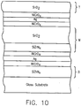
- Figure 10 is a cross sectional view of a coated article according to another comparative example.
- the Fig. 10 embodiment differs from the Fig. 9 embodiment in that the upper silicon oxide and SiZrN inclusive layers in the top dielectric portion T have been removed.
- the silicon zirconium nitride inclusive layers may be stoichiometric or non-stoichiometric.
- one or more of the silicon zirconium nitride (SiZrN) layers may be oxided, and/or may be replaced with layer(s) comprising niobium oxide (e.g., Nb 2 O 5 or any other suitable form).
- the coated article of Fig. 10 includes from the glass substrate outwardly (all indices n at 550 nm):
- the layer system can be characterized by the top dielectric portion T having an effective index of refraction n less than that of middle dielectric portion M, which in turn has an effective index of refraction n less than that of the bottom dielectric portion B.
- n T ⁇ n M ⁇ n B where n T is the effective index of refraction of the top dielectric portion T, n M is the effective index of refraction of the middle dielectric portion M, and n B is the effective index of refraction of the bottom dielectric portion B.
- Each of the top, middle and bottom dielectric portions T, M and B, respectively, can include a plurality of different dielectric layers, although in alternative embodiments any or all of these portions need only include a single dielectric layer.
- the anti-reflection system of this embodiment enables increased visible transmission to be achieved.
- the anti-reflection system may also enable fairly neutral color of the coated article in certain example embodiments.
- Example 1 of the Fig. 10 embodiment compared to a Comparative Example(s) (CE) similar to Fig. 1 of the instant application.
- the CE relates to a coating that is similar to that illustrated in the 09/794,224 application.
- the thicknesses for each of the layers in the First Table below are in angstroms ( ⁇ ).
- the Second Table below sets forth the optical characteristics (e.g., visible transmission, color, etc.) for Example 1 and the CE based upon being annealed and in monolithic form.
- Example 1 had better visible transmission (higher T vis ) and better glass and/or film side reflection (lower R g and/or R f ) than the Comparative Example (CE - see Fig. 1 ). Surprisingly, Example 1 also had fairly neutral transmissive color.
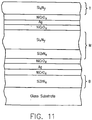
- Figure 11 is a cross sectional view of a coated article according to another comparative example.
- the Fig. 11 embodiment differs from the Fig. 10 embodiment in that the upper and middle tin oxide layers from Fig. 10 are replaced with respective layers of or including silicon nitride (stoichiometric or non-stoichiometric).
- silicon nitride silicon zirconium nitride inclusive layers may be stoichiometric or non-stoichiometric.
- one or more of the silicon zirconium nitride (SiZrN) layers may be oxided, and/or may be replaced with layer(s) comprising niobium oxide (e.g., Nb 2 O 5 or any other suitable form).
- the coated article of Fig. 11 includes from the glass substrate outwardly (all indices n at 550 nm):
- the layer system can be characterized by the top dielectric portion T having an effective index of refraction n less than that of middle dielectric portion M, which in turn has an effective index of refraction n less than that of the bottom dielectric portion B.
- n T ⁇ n M ⁇ n B where n T is the effective index of refraction of the top dielectric portion T, n M is the effective index of refraction of the middle dielectric portion M, and n B is the effective index of refraction of the bottom dielectric portion B.
- Each of the top, middle and bottom dielectric portions T, M and B, respectively, can include a plurality of different dielectric layers, although in alternative embodiments any or all of these portions need only include a single dielectric layer.
- the anti-reflection system of this embodiment enables increased visible transmission to be achieved.
- the anti-reflection system may also enable fairly neutral color of the coated article in certain example embodiments.
- Example 1 of the Fig. 11 embodiment compared to a Comparative Example(s) (CE) similar to Fig. 1 of the instant application.
- the CE relates to a coating that is similar to that illustrated in the 09/794,224 application.
- the thicknesses for each of the layers in the First Table below are in angstroms ( ⁇ ).
- the Second Table below sets forth the optical characteristics (e.g., visible transmission, color, etc.) for Example 1 and the CE based upon being annealed and in monolithic form.
- Example 1 had better visible transmission (higher T vis ) and better glass and/or film side reflection (lower R g and/or R f ) than the Comparative Example (CE - see Fig. 1 ). Surprisingly, Example 1 also had fairly neutral color.
- Figure 12 is a cross sectional view of a coated article according to another comparative example.
- the Fig. 12 embodiment differs from Fig. 1 in that (a) the bottom titanium oxide and silicon nitride layers in bottom portion B of Fig. 1 have been removed and replaced with a layer of or including niobium oxide (stoichiometric Nb 2 O 5 , or some non-stoichiometic form), (b) the silicon nitride layer in the middle portion M of Fig. 1 has been removed, (c) a layer of or including niobium oxide (stoichiometric Nb 2 O 5 , or some non-stoichiometic form) has been added to the middle dielectric portion M in Fig.
- the coated article of Fig. 12 includes from the glass substrate outwardly (all indices n at 550 nm):
- the layer system can be characterized by the top dielectric portion T having an effective index of refraction n less than that of middle dielectric portion M, which in turn has an effective index of refraction n less than that of the bottom dielectric portion B.
- n T ⁇ n M ⁇ n B where n T is the effective index of refraction of the top dielectric portion T, n M is the effective index of refraction of the middle dielectric portion M, and n B is the effective index of refraction of the bottom dielectric portion B.
- Each of the top, middle and bottom dielectric portions T, M and B, respectively, can include a plurality of different dielectric layers, although in alternative embodiments any or all of these portions need only include a single dielectric layer.
- the anti-reflection system of this embodiment enables increased visible transmission to be achieved.
- the anti-reflection system may also enable fairly neutral color of the coated article in certain example embodiments.
- Example 1 of the Fig. 12 embodiment compared to a Comparative Example(s) (CE) similar to Fig. 1 of the instant application.
- the CE relates to a coating that is similar to that illustrated in the 09/794,224 application.
- the thicknesses for each of the layers in the First Table below are in angstroms ( ⁇ ).
- the Second Table below sets forth the optical characteristics (e.g., visible transmission, color, etc.) for Example 1 and the CE based upon being annealed and in monolithic form.
- Example 1 had better visible transmission (higher T vis ) and better glass and/or film side reflection (lower R g and/or R f ) than the Comparative Example (CE - see Fig. 1 ). Surprisingly, Example 1 also had more neutral transmissive and glass side reflective color than the CE.
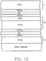
- Figure 13 is a cross sectional view of a coated article according to another comparative example.
- the Fig. 13 embodiment differs from the Fig. 12 embodiment in that the top silicon oxide and niobium oxide layers in top dielectric portion T of Fig. 12 have been removed.
- the coated article of Fig. 13 includes from the glass substrate outwardly (all indices n at 550 nm):
- the layer system can be characterized by the top dielectric portion T having an effective index of refraction n less than that of middle dielectric portion M, which in turn has an effective index of refraction n less than that of the bottom dielectric portion B.
- n T ⁇ n M ⁇ n B where n T is the effective index of refraction of the top dielectric portion T, n M is the effective index of refraction of the middle dielectric portion M, and n B is the effective index of refraction of the bottom dielectric portion B.
- Each of the top, middle and bottom dielectric portions T, M and B, respectively, can include a plurality of different dielectric layers, although in alternative embodiments any or all of these portions need only include a single dielectric layer.
- the anti-reflection system of this embodiment enables increased visible transmission to be achieved.
- the anti-reflection system may also enable fairly neutral color of the coated article in certain example embodiments.
- Example 1 of the Fig. 13 embodiment compared to a Comparative Example(s) (CE) similar to Fig. 1 of the instant application.
- the CE relates to a coating that is similar to that illustrated in the 09/794,224 application.
- the thicknesses for each of the layers in the First Table below are in angstroms ( ⁇ ).
- the Second Table below sets forth the optical characteristics (e.g., visible transmission, color, etc.) for Example 1 and the CE based upon being annealed and in monolithic form.
- Example 1 had better visible transmission (higher T vis ) and better glass and/or film side reflection (lower R g and/or R f ) than the Comparative Example (CE - see Fig. 1 ). Surprisingly, Example 1 also had more neutral transmissive and glass side reflective color than the CE.
- Figure 14 is a cross sectional view of a coated article according to another comparative example.
- the Fig. 14 embodiment differs from the Fig. 13 embodiment in that the top tin oxide layer of Fig. 13 has been replaced with a silicon nitride inclusive layer in Fig. 14 .
- the coated article of Fig. 14 includes from the glass substrate outwardly (all indices n at 550 nm):
- the layer system can be characterized by the top dielectric portion T having an effective index of refraction n less than that of middle dielectric portion M, which in turn has an effective index of refraction n less than that of the bottom dielectric portion B.
- n T ⁇ n M ⁇ n B where n T is the effective index of refraction of the top dielectric portion T, n M is the effective index of refraction of the middle dielectric portion M, and n B is the effective index of refraction of the bottom dielectric portion B.
- Each of the top, middle and bottom dielectric portions T, M and B, respectively, can include a plurality of different dielectric layers, although in alternative embodiments any or all of these portions need only include a single dielectric layer.
- the anti-reflection system of this embodiment enables increased visible transmission to be achieved.
- the anti-reflection system may also enable fairly neutral color of the coated article in certain example embodiments.
- Example 1 of the Fig. 14 embodiment compared to a Comparative Example(s) (CE) similar to Fig. 1 of the instant application.
- the CE relates to a coating that is similar to that illustrated in the 09/794,224 application.
- the thicknesses for each of the layers in the First Table below are in angstroms ( ⁇ ).
- the Second Table below sets forth the optical characteristics (e.g., visible transmission, color, etc.) for Example 1 and the CE based upon being annealed and in monolithic form.
- Example 1 had better visible transmission (higher T vis ) and better glass and/or film side reflection (lower R g and/or R f ) than the Comparative Example (CE - see Fig. 1 ). Surprisingly, Example 1 also had more neutral transmissive and glass side reflective color than the CE.
- Figure 15 is a cross sectional view of a coated article according to another comparative example.
- the Fig. 15 embodiment differs from the Fig. 12 embodiment in that the two upper nickel chrome oxide contact layers have been removed from the Fig. 12 embodiment.
- the coated article of Fig. 15 includes from the glass substrate outwardly (all indices n at 550 nm):
- the layer system can be characterized by the top dielectric portion T having an effective index of refraction n less than that of middle dielectric portion M, which in turn has an effective index of refraction n less than that of the bottom dielectric portion B.
- n T ⁇ n M ⁇ n B where n T is the effective index of refraction of the top dielectric portion T, n M is the effective index of refraction of the middle dielectric portion M, and n B is the effective index of refraction of the bottom dielectric portion B.
- Each of the top, middle and bottom dielectric portions T, M and B, respectively, can include a plurality of different dielectric layers, although in alternative embodiments any or all of these portions need only include a single dielectric layer.
- the anti-reflection system of this embodiment enables increased visible transmission to be achieved.
- the anti-reflection system may also enable fairly neutral color of the coated article in certain example embodiments.
- Example 1 of the Fig. 15 embodiment compared to a Comparative Example(s) (CE) similar to Fig. 1 of the instant application.
- the CE relates to a coating that is similar to that illustrated in the 09/794,224 application.
- the thicknesses for each of the layers in the First Table below are in angstroms ( ⁇ ).
- the Second Table below sets forth the optical characteristics (e.g., visible transmission, color, etc.) for Example 1 and the CE based upon being annealed and in monolithic form.
- Example 1 had better visible transmission (higher T vis ) and better glass and/or film side reflection (lower R g and/or R f ) than the Comparative Example (CE - see Fig. 1 ). Surprisingly, Example 1 also had more neutral color than the CE.
- Figure 16 is a cross sectional view of a coated article according to another comparative example.
- the Fig. 16 embodiment differs from the Fig. 15 embodiment in that the upper silicon oxide and tin oxide layers in top dielectric portion T have been replaced with a layer of or including silicon oxynitride.
- the coated article of Fig. 16 includes from the glass substrate outwardly (all indices n at 550 nm):
- the layer system can be characterized by the top dielectric portion T having an effective index of refraction n less than that of middle dielectric portion M, which in turn has an effective index of refraction n less than that of the bottom dielectric portion B.
- n T ⁇ n M ⁇ n B where n T is the effective index of refraction of the top dielectric portion T, n M is the effective index of refraction of the middle dielectric portion M, and n B is the effective index of refraction of the bottom dielectric portion B.
- Each of the top, middle and bottom dielectric portions T, M and B, respectively, can include a plurality of different dielectric layers, although in alternative embodiments any or all of these portions need only include a single dielectric layer.
- the anti-reflection system of this embodiment enables increased visible transmission to be achieved.
- the anti-reflection system may also enable fairly neutral color of the coated article in certain example embodiments.
- the silicon oxynitride layer is beneficial in that its index of refraction n (at 550 nm) can be varied from 1.45 to 2.0, more preferably from 1.6 to 1.9, and most preferably from 1.65 to 1.85.
- the silicon oxynitride layer may have a constant (or approximately constant, i.e., constant plus/minus about 5%) index of refraction n throughout its entire thickness, but alternatively may be oxidation and/or nitride graded so as to have an index of refraction n which varies through the thickness of the layer (e.g., the index n may gradually decrease through the thickness of the silicon oxynitride layer moving toward the air).
- Example 1 of the Fig. 16 embodiment compared to a Comparative Example(s) (CE) similar to Fig. 1 of the instant application.
- the CE relates to a coating that is similar to that illustrated in the 09/794,224 application.
- the thicknesses for each of the layers in the First Table below are in angstroms ( ⁇ ).
- the Second Table below sets forth the optical characteristics (e.g., visible transmission, color, etc.) for Example 1 and the CE based upon being annealed and in monolithic form.
- Example 1 had better visible transmission (higher T vis ) and better glass and/or film side reflection (lower R g and/or R f ) than the Comparative Example (CE - see Fig. 1 ). Surprisingly, Example 1 also had more neutral color than the CE (especially glass side reflective color).
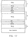
- Figure 17 is a cross sectional view of a coated article according to another comparative example.
- the Fig. 17 embodiment differs from the Fig. 14 embodiment in that an additional niobium oxide layer has been added to the top dielectric portion T, and the two top contact layers were NiCr (i.e. not significantly oxided).
- the coated article of Fig. 17 includes from the glass substrate outwardly (all indices n at 550 nm):
- the layer system can be characterized by the top dielectric portion T having an effective index of refraction n less than or equal to that of middle dielectric portion M, which in turn has an effective index of refraction n less than or equal to that of the bottom dielectric portion B.
- Each of the top, middle and bottom dielectric portions T, M and B, respectively, can include a plurality of different dielectric layers, although in alternative embodiments any or all of these portions need only include a single dielectric layer.
- the anti-reflection system of this embodiment enables increased visible transmission to be achieved.
- the anti-reflection system may also enable fairly neutral color of the coated article in certain example embodiments. While the two upper contact layers were NiCr (not significantly oxided) in this embodiment, it will be recognized by those skilled in the art that in other embodiments these NiCr contact layers may be nitrided.
- Example 1 of the Fig. 17 embodiment compared to a Comparative Example(s) (CE) similar to Fig. 1 of the instant application.
- the CE relates to a coating that is similar to that illustrated in the 09/794,224 application.
- the thicknesses for each of the layers in the First Table below are in angstroms ( ⁇ ).
- the Second Table below sets forth the optical characteristics (e.g., visible transmission, color, etc.) for Example 1 and the CE based upon being annealed and in monolithic form.
- Example 1 had better visible transmission (higher T vis ) and better glass and/or film side reflection (lower R g and/or R f ) than the Comparative Example (CE - see Fig. 1 ). Fairly neutral transmissive color was also provided in Example 1.
Claims (16)
- Beschichteter Gegenstand einschließlich einer von einem Glassubstrat getragenen Beschichtung, wobei die Beschichtung besteht aus:ersten und zweiten infrarotreflektierenden Schichten, die Silber umfassen, undoberen, mittleren und unteren dielektrischen Abschnitten (T, M, B), die jeweils mindestens eine dielektrische Schicht beinhalten, wobeider obere dielektrische Abschnitt (T) einen effektiven Brechungsindex m aufweist und oberhalb der oberen infrarotreflektierenden Schicht bereitgestellt ist, wobei der effektive Index nT als gewichteter Mittelwert des oberen dielektrischen Abschnitts (T) berechnet wird,der mittlere dielektrische Abschnitt (M) einen effektiven Brechungsindex nM aufweist und zwischen den infrarotreflektierenden Schichten bereitgestellt ist, wobei der effektive Index nM als gewichteter Mittelwert des mittleren dielektrischen Abschnitts (M) berechnet wird,und der untere dielektrische Abschnitt (B) einen effektiven Brechungsindex nB aufweist und unter der unteren infrarotreflektierenden Schicht bereitgestellt ist, wobei der effektive Index nB als gewichteter Mittelwert des unteren dielektrischen Abschnitts (B) berechnet wird, und wobei nT < nM < nB ist, wobeider untere dielektrische Abschnitt (B) eine erste Titanoxid umfassende dielektrische Schicht umfasst, die zwischen der ersten IR-reflektierenden Schicht und dem Glassubstrat bereitgestellt ist, wobeider mittlere dielektrische Abschnitt (M) eine zweite dielektrische Schicht umfasst, die einen Brechungsindex von 1,8 < = n < = 2,2 aufweist, die zwischen den ersten und zweiten infrarotreflektierenden Schichten bereitgestellt ist, wobei die zweite dielektrische Schicht einen Brechungsindex n kleiner als der Brechungsindex n der ersten dielektrischen Schicht aufweist, wobeider obere dielektrische Abschnitt (T) eine dritte Titanoxid umfassende dielektrische Schicht, die über den ersten und zweiten infrarotreflektierenden Schichten bereitgestellt ist, und eine vierte Siliziumoxid umfassende dielektrische Schicht umfasst, die über der dritten Titanoxid umfassenden dielektrischen Schicht bereitgestellt ist; undwobei der beschichtete Gegenstand eine Transmission von sichtbarem Licht von mindestens 70 % aufweist.
- Beschichteter Gegenstand nach Anspruch 1, wobei die zweite dielektrische Schicht Zinnoxid umfasst.
- Beschichteter Gegenstand nach Anspruch 1, ferner umfassend eine weitere Titanoxid umfassende dielektrische Schicht, die zwischen den ersten und zweiten infrarotreflektierenden Schichten angeordnet ist.
- Beschichteter Gegenstand nach Anspruch 3, wobei die weitere Titanoxid umfassende dielektrische Schicht unter der zweiten dielektrischen Schicht angeordnet ist.
- Beschichteter Gegenstand nach Anspruch 3, ferner umfassend eine weitere Zinnoxid umfassende dielektrische Schicht, die zwischen der dritten Titanoxid umfassenden dielektrischen Schicht und der vierten Siliziumoxid umfassenden dielektrischen Schicht angeordnet ist.
- Beschichteter Gegenstand nach Anspruch 1, wobei die erste Titanoxid umfassende dielektrische Schicht TiO2 beinhaltet und wobei das Siliziumoxid SiO2 umfasst.
- IG-Fenstereinheit, die den beschichteten Gegenstand nach Anspruch 1 umfasst.
- Beschichteter Gegenstand einschließlich einer von einem Glassubstrat getragenen Beschichtung, wobei die Beschichtung aus ersten und zweiten infrarotreflektierenden Schichten besteht, die jeweils mindestens eines aus Silber und Gold und obere, mittlere und untere dielektrische Abschnitte (T, M, B) umfassen, die jeweils mindestens eine dielektrische Schicht beinhalten, wobei
der obere dielektrische Abschnitt (T) einen effektiven Brechungsindex nT aufweist und oberhalb der oberen infrarotreflektierenden Schicht bereitgestellt ist, wobei der effektive Index nT als gewichteter Mittelwert des oberen dielektrischen Abschnitts (T) berechnet wird,
der mittlere dielektrische Abschnitt (M) einen effektiven Brechungsindex nM aufweist und zwischen den infrarotreflektierenden Schichten bereitgestellt ist, wobei der effektive Index nM als gewichteter Mittelwert des mittleren dielektrischen Abschnitts (M) berechnet wird,
und der untere dielektrische Abschnitt (B) einen effektiven Brechungsindex m aufweist und unter der unteren infrarotreflektierenden Schicht bereitgestellt ist, wobei der effektive Index ns als gewichteter Mittelwert des unteren dielektrischen Abschnitts (B) berechnet wird, und wobei nT < nM < nB ist, und
wobei der untere dielektrische Abschnitt (B) eine erste Titanoxid umfassende dielektrische Schicht umfasst, die zwischen der ersten infrarotreflektierenden Schicht und dem Glassubstrat bereitgestellt ist, wobei
der mittlere dielektrische Abschnitt (M) eine zweite Titanoxid umfassende dielektrische Schicht, die zwischen den ersten und zweiten infrarotreflektierenden Schichten bereitgestellt ist, und eine dritte dielektrische Schicht umfasst, die einen Brechungsindex von 1,8 < = n < = 2,2 aufweist, die zwischen den ersten und zweiten infrarotreflektierenden Schichten bereitgestellt ist, wobei die dritte dielektrische Schicht einen Brechungsindex n kleiner als der Brechungsindex n von mindestens einer der ersten und zweiten dielektrischen Schichten aufweist, und wobei
der obere dielektrische Abschnitt (T) eine vierte Siliziumoxid umfassende dielektrische Schicht umfasst, die über den ersten und zweiten infrarotreflektierenden Schichten bereitgestellt ist; und
wobei der beschichtete Gegenstand eine Transmission von sichtbarem Licht von mindestens 70 % aufweist. - Beschichteter Gegenstand nach Anspruch 8, wobei die dritte dielektrische Schicht Zinnoxid umfasst.
- Beschichteter Gegenstand nach Anspruch 8, ferner umfassend eine weitere Siliziumnitrid umfassende dielektrische Schicht, die zwischen der zweiten infrarotreflektierenden Schicht und der vierten Siliziumoxid umfassenden dielektrischen Schicht bereitgestellt ist.
- Beschichteter Gegenstand nach Anspruch 8, ferner umfassend eine weitere Titanoxid umfassende dielektrische Schicht, die zwischen der zweiten infrarotreflektierenden Schicht und der vierten Siliziumoxid umfassenden dielektrischen Schicht bereitgestellt ist.
- Beschichteter Gegenstand nach Anspruch 8, ferner umfassend eine weitere Zinnoxid umfassende dielektrische Schicht, die zwischen der zweiten infrarotreflektierenden Schicht und der vierten Siliziumoxid umfassenden dielektrischen Schicht bereitgestellt ist.
- Beschichteter Gegenstand nach Anspruch 3 oder 8, ferner umfassend eine weitere Siliziumnitrid umfassende dielektrische Schicht, die zwischen der ersten Titanoxid umfassenden dielektrischen Schicht und der ersten infrarotreflektierenden Schicht angeordnet ist.
- Beschichteter Gegenstand nach Anspruch 1 oder 8, wobei sowohl die erste als auch die zweite infrarotreflektierende Schicht Ag umfasst und sandwichartig zwischen einem Paar Kontaktschichten angeordnet ist und wobei mindestens eine der Kontaktschichten neben jeder infrarotreflektierenden Schicht mindestens eines aus NiCr, NiCrOx und NiCrNx umfasst.
- Beschichteter Gegenstand nach Anspruch 8, wobei die ersten und zweiten Titanoxid umfassenden dielektrischen Schichten jeweils TiO2 beinhalten.
- Fenster, das den beschichteten Gegenstand nach Anspruch 8 umfasst.
Priority Applications (1)
| Application Number | Priority Date | Filing Date | Title |
|---|---|---|---|
| EP10177845A EP2338851A1 (de) | 2001-12-21 | 2002-12-16 | Anti-Reflektionsschichtsystem auf einem Glassubsrat mit hoher Transmission für sichtbares Licht und geringer Emissionsfähigkeit |
Applications Claiming Priority (3)
| Application Number | Priority Date | Filing Date | Title |
|---|---|---|---|
| US10/024,613 US6830817B2 (en) | 2001-12-21 | 2001-12-21 | Low-e coating with high visible transmission |
| US24613 | 2001-12-21 | ||
| PCT/US2002/040076 WO2003055816A2 (en) | 2001-12-21 | 2002-12-16 | Anti-reflection layer system on a glass substrate with high visible transmission and a low e |
Related Child Applications (1)
| Application Number | Title | Priority Date | Filing Date |
|---|---|---|---|
| EP10177845A Division-Into EP2338851A1 (de) | 2001-12-21 | 2002-12-16 | Anti-Reflektionsschichtsystem auf einem Glassubsrat mit hoher Transmission für sichtbares Licht und geringer Emissionsfähigkeit |
Publications (2)
| Publication Number | Publication Date |
|---|---|
| EP1458653A2 EP1458653A2 (de) | 2004-09-22 |
| EP1458653B1 true EP1458653B1 (de) | 2019-04-17 |
Family
ID=21821495
Family Applications (2)
| Application Number | Title | Priority Date | Filing Date |
|---|---|---|---|
| EP02797326.2A Expired - Fee Related EP1458653B1 (de) | 2001-12-21 | 2002-12-16 | Anti-reflektions schichtsystem auf einem glassubsrat mit hoher transmission für sichtbares licht und geringer emissionsfähigkeit |
| EP10177845A Withdrawn EP2338851A1 (de) | 2001-12-21 | 2002-12-16 | Anti-Reflektionsschichtsystem auf einem Glassubsrat mit hoher Transmission für sichtbares Licht und geringer Emissionsfähigkeit |
Family Applications After (1)
| Application Number | Title | Priority Date | Filing Date |
|---|---|---|---|
| EP10177845A Withdrawn EP2338851A1 (de) | 2001-12-21 | 2002-12-16 | Anti-Reflektionsschichtsystem auf einem Glassubsrat mit hoher Transmission für sichtbares Licht und geringer Emissionsfähigkeit |
Country Status (6)
| Country | Link |
|---|---|
| US (3) | US6830817B2 (de) |
| EP (2) | EP1458653B1 (de) |
| AU (1) | AU2002361688A1 (de) |
| CA (1) | CA2467714C (de) |
| PL (1) | PL203913B1 (de) |
| WO (1) | WO2003055816A2 (de) |
Families Citing this family (98)
| Publication number | Priority date | Publication date | Assignee | Title |
|---|---|---|---|---|
| US7153577B2 (en) * | 2000-07-10 | 2006-12-26 | Guardian Industries Corp. | Heat treatable coated article with dual layer overcoat |
| US6830817B2 (en) * | 2001-12-21 | 2004-12-14 | Guardian Industries Corp. | Low-e coating with high visible transmission |
| US6770321B2 (en) * | 2002-01-25 | 2004-08-03 | Afg Industries, Inc. | Method of making transparent articles utilizing protective layers for optical coatings |
| EP1375445A1 (de) * | 2002-06-17 | 2004-01-02 | Glaverbel | Verfahren zur Herstellung einer Verglasung mit einer mehrlagigen Beschichtung |
| US6881487B2 (en) * | 2002-11-15 | 2005-04-19 | Guardian Industries Corp. | Heat treatable coated articles with zirconium or zirconium nitride layer and methods of making same |
| US7005190B2 (en) * | 2002-12-20 | 2006-02-28 | Guardian Industries Corp. | Heat treatable coated article with reduced color shift at high viewing angles |
| FR2858816B1 (fr) | 2003-08-13 | 2006-11-17 | Saint Gobain | Substrat transparent comportant un revetement antireflet |
| CN101854794A (zh) * | 2003-08-25 | 2010-10-06 | 旭硝子株式会社 | 电磁波屏蔽层叠体及利用该电磁波屏蔽层叠体的显示装置 |
| ATE461437T1 (de) * | 2004-01-27 | 2010-04-15 | Mettler Toledo Ag | Dehnmessstreifen mit feuchtigkeitsschutz durch inhomogene anorganische schicht auf glättender polymerschicht (ormocer) und schlitzanordnung |
| US7217460B2 (en) * | 2004-03-11 | 2007-05-15 | Guardian Industries Corp. | Coated article with low-E coating including tin oxide interlayer |
| US7294402B2 (en) * | 2004-03-05 | 2007-11-13 | Guardian Industries Corp. | Coated article with absorbing layer |
| DE102004047135B4 (de) * | 2004-09-27 | 2011-08-18 | VON ARDENNE Anlagentechnik GmbH, 01324 | Temperfähiges Schichtsystem und Verfahren zu seiner Herstellung |
| US7291251B2 (en) * | 2004-10-19 | 2007-11-06 | Centre Luxembourgeois De Recherches Pour Le Verre Et La Ceramique S.A. (C.R.V.C.) | Method of making coated article with IR reflecting layer(s) using krypton gas |
| US7390572B2 (en) * | 2004-11-05 | 2008-06-24 | Centre Luxembourgeois De Recherches Pour Le Verre Et La Ceramique S.A. (C.R.V.C.) | Coated article with IR reflecting layer(s) and method of making same |
| US7153578B2 (en) * | 2004-12-06 | 2006-12-26 | Guardian Industries Corp | Coated article with low-E coating including zirconium silicon oxynitride and methods of making same |
| US7592068B2 (en) * | 2005-01-19 | 2009-09-22 | Centre Luxembourgeois De Recherches Pour Le Verre Et La Ceramique S.A. (C.R.V.C.) | Heat treatable coated article with zirconium silicon oxynitride layer(s) and methods of making same |
| FR2881757B1 (fr) * | 2005-02-08 | 2007-03-30 | Saint Gobain | Procede d'elaboration par projection thermique d'une cible a base de silicium et de zirconium |
| MX2007014164A (es) | 2005-05-12 | 2008-02-25 | Agc Flat Glass North America | Recubrimiento de baja emisividad con bajo coeficiente de ganancia de calor solar, propiedades quimicas y mecanicas mejoradas y metodo para fabricar el mismo. |
| US7342716B2 (en) * | 2005-10-11 | 2008-03-11 | Cardinal Cg Company | Multiple cavity low-emissivity coatings |
| US7339728B2 (en) * | 2005-10-11 | 2008-03-04 | Cardinal Cg Company | Low-emissivity coatings having high visible transmission and low solar heat gain coefficient |
| US7572511B2 (en) * | 2005-10-11 | 2009-08-11 | Cardinal Cg Company | High infrared reflection coatings |
| US20090220802A1 (en) * | 2006-02-21 | 2009-09-03 | Von Ardenne Anlagentechnik Gmbh | Highly reflective layer system, method for producing the layer system and device for carrying out the method |
| FR2898123B1 (fr) * | 2006-03-06 | 2008-12-05 | Saint Gobain | Substrat muni d'un empilement a proprietes thermiques |
| DE102006014796B4 (de) * | 2006-03-29 | 2009-04-09 | Saint-Gobain Glass Deutschland Gmbh | Thermisch hoch belastbares Low-E-Schichtsystem für transparente Substrate |
| JP2009538815A (ja) | 2006-05-31 | 2009-11-12 | エージーシー フラット グラス ユーロップ エスエー | 低放射率板ガラス |
| US8420162B2 (en) * | 2006-07-07 | 2013-04-16 | Guardian Industries Corp. | Method of making coated article using rapid heating for reducing emissivity and/or sheet resistance, and corresponding product |
| US7695785B2 (en) * | 2006-07-14 | 2010-04-13 | Guardian Industries Corp. | Coated article with oxides and/or oxynitrides of antimony and/or zinc dielectric layer(s) and corresponding method |
| EP2070104A2 (de) | 2006-07-25 | 2009-06-17 | David W. Cunningham | Glühlampe mit infrarotreflektierendem beschichtungssystem und leuchte mit derartiger lampe |
| US20080105299A1 (en) * | 2006-11-02 | 2008-05-08 | Guardian Industries Corp. | Front electrode with thin metal film layer and high work-function buffer layer for use in photovoltaic device and method of making same |
| US20080105293A1 (en) * | 2006-11-02 | 2008-05-08 | Guardian Industries Corp. | Front electrode for use in photovoltaic device and method of making same |
| US20080105298A1 (en) * | 2006-11-02 | 2008-05-08 | Guardian Industries Corp. | Front electrode for use in photovoltaic device and method of making same |
| US8203073B2 (en) * | 2006-11-02 | 2012-06-19 | Guardian Industries Corp. | Front electrode for use in photovoltaic device and method of making same |
| US20080178932A1 (en) * | 2006-11-02 | 2008-07-31 | Guardian Industries Corp. | Front electrode including transparent conductive coating on patterned glass substrate for use in photovoltaic device and method of making same |
| US7964788B2 (en) * | 2006-11-02 | 2011-06-21 | Guardian Industries Corp. | Front electrode for use in photovoltaic device and method of making same |
| US8076571B2 (en) * | 2006-11-02 | 2011-12-13 | Guardian Industries Corp. | Front electrode for use in photovoltaic device and method of making same |
| US20080302414A1 (en) * | 2006-11-02 | 2008-12-11 | Den Boer Willem | Front electrode for use in photovoltaic device and method of making same |
| US8012317B2 (en) * | 2006-11-02 | 2011-09-06 | Guardian Industries Corp. | Front electrode including transparent conductive coating on patterned glass substrate for use in photovoltaic device and method of making same |
| US7632543B2 (en) | 2006-12-05 | 2009-12-15 | Guardian Industries Corp. | Method of making IG window unit and forming silicon oxide based hydrophilic coating using chlorosilane vapor deposition |
| JP5245251B2 (ja) * | 2006-12-27 | 2013-07-24 | ソニー株式会社 | 光学的素子及び光学装置、並びに光学的素子の製造方法 |
| FR2911130B1 (fr) * | 2007-01-05 | 2009-11-27 | Saint Gobain | Procede de depot de couche mince et produit obtenu |
| US8334452B2 (en) | 2007-01-08 | 2012-12-18 | Guardian Industries Corp. | Zinc oxide based front electrode doped with yttrium for use in photovoltaic device or the like |
| US20080169021A1 (en) * | 2007-01-16 | 2008-07-17 | Guardian Industries Corp. | Method of making TCO front electrode for use in photovoltaic device or the like |
| US9577137B2 (en) * | 2007-01-25 | 2017-02-21 | Au Optronics Corporation | Photovoltaic cells with multi-band gap and applications in a low temperature polycrystalline silicon thin film transistor panel |
| US20080179762A1 (en) * | 2007-01-25 | 2008-07-31 | Au Optronics Corporation | Layered structure with laser-induced aggregation silicon nano-dots in a silicon-rich dielectric layer, and applications of the same |
| US20080223430A1 (en) * | 2007-03-14 | 2008-09-18 | Guardian Industries Corp. | Buffer layer for front electrode structure in photovoltaic device or the like |
| US20080308145A1 (en) * | 2007-06-12 | 2008-12-18 | Guardian Industries Corp | Front electrode including transparent conductive coating on etched glass substrate for use in photovoltaic device and method of making same |
| US20080308146A1 (en) * | 2007-06-14 | 2008-12-18 | Guardian Industries Corp. | Front electrode including pyrolytic transparent conductive coating on textured glass substrate for use in photovoltaic device and method of making same |
| US7888594B2 (en) * | 2007-11-20 | 2011-02-15 | Guardian Industries Corp. | Photovoltaic device including front electrode having titanium oxide inclusive layer with high refractive index |
| US7901781B2 (en) | 2007-11-23 | 2011-03-08 | Agc Flat Glass North America, Inc. | Low emissivity coating with low solar heat gain coefficient, enhanced chemical and mechanical properties and method of making the same |
| US20090194157A1 (en) * | 2008-02-01 | 2009-08-06 | Guardian Industries Corp. | Front electrode having etched surface for use in photovoltaic device and method of making same |
| US20090194155A1 (en) * | 2008-02-01 | 2009-08-06 | Guardian Industries Corp. | Front electrode having etched surface for use in photovoltaic device and method of making same |
| PL2138667T3 (pl) * | 2008-06-25 | 2012-03-30 | Scheuten S A R L | Potrójne oszklenie izolujące |
| TWI462307B (zh) * | 2008-09-02 | 2014-11-21 | Au Optronics Corp | 具備多重能隙的矽奈米晶體光電池及其在一低溫多晶矽薄膜電晶體面板內之應用 |
| US8022291B2 (en) * | 2008-10-15 | 2011-09-20 | Guardian Industries Corp. | Method of making front electrode of photovoltaic device having etched surface and corresponding photovoltaic device |
| MX2011008352A (es) | 2009-02-09 | 2011-11-28 | Semprius Inc | Modulos, receptores y sub-receptores fotovoltaicos tipo concentrador y metodos para formar los mismos. |
| FR2942794B1 (fr) * | 2009-03-09 | 2011-02-18 | Saint Gobain | Substrat muni d'un empilement a proprietes thermiques comportant des couches a haut indice de refraction |
| US8289610B2 (en) | 2009-08-27 | 2012-10-16 | Guardian Industries Corp. | Electrochromic devices, assemblies incorporating electrochromic devices, and/or methods of making the same |
| KR101642708B1 (ko) * | 2010-01-19 | 2016-07-28 | 삼성전자주식회사 | 화상형성장치와 그 프리뷰 이미지 디스플레이방법, 및 서버와 그 프리뷰 이미지 제공방법 |
| US8524337B2 (en) | 2010-02-26 | 2013-09-03 | Guardian Industries Corp. | Heat treated coated article having glass substrate(s) and indium-tin-oxide (ITO) inclusive coating |
| US8815059B2 (en) | 2010-08-31 | 2014-08-26 | Guardian Industries Corp. | System and/or method for heat treating conductive coatings using wavelength-tuned infrared radiation |
| US8939606B2 (en) | 2010-02-26 | 2015-01-27 | Guardian Industries Corp. | Heatable lens for luminaires, and/or methods of making the same |
| US8834976B2 (en) | 2010-02-26 | 2014-09-16 | Guardian Industries Corp. | Articles including anticondensation and/or low-E coatings and/or methods of making the same |
| US8808882B2 (en) | 2010-09-17 | 2014-08-19 | Guardian Industries Corp. | Coated article having boron doped zinc oxide based seed layer with enhanced durability under functional layer and method of making the same |
| US8815420B2 (en) | 2010-09-17 | 2014-08-26 | Guardian Industries Corp. | Coated article having zinc oxide seed layer with reduced stress under functional layer and method of making the same |
| FR2970248B1 (fr) * | 2011-01-06 | 2019-08-30 | Saint-Gobain Glass France | Substrat muni d'un empilement a proprietes thermiques, en particulier pour realiser un vitrage chauffant. |
| CN102691033B (zh) * | 2011-03-22 | 2014-12-31 | 鸿富锦精密工业(深圳)有限公司 | 抗菌镀膜件及其制备方法 |
| CN102691035A (zh) * | 2011-03-22 | 2012-09-26 | 鸿富锦精密工业(深圳)有限公司 | 抗菌镀膜件及其制备方法 |
| WO2012127162A1 (fr) * | 2011-03-24 | 2012-09-27 | Saint-Gobain Glass France | Substrat transparent muni d'un empilement de couches minces |
| CN102503172A (zh) * | 2011-10-31 | 2012-06-20 | 中山市格兰特实业有限公司火炬分公司 | 一种低辐射可钢化双银low-e玻璃 |
| US9556066B2 (en) | 2011-12-13 | 2017-01-31 | Guardian Industries Corp. | Insulating glass units with low-E and antireflective coatings, and/or methods of making the same |
| US9221713B2 (en) | 2011-12-21 | 2015-12-29 | Centre Luxembourgeois De Recherches Pour Le Verre Et La Ceramique S.A. (C.R.V.C.) | Coated article with low-E coating having barrier layer system(s) including multiple dielectric layers, and/or methods of making the same |
| US8940399B2 (en) * | 2012-10-04 | 2015-01-27 | Guardian Industries Corp. | Coated article with low-E coating having low visible transmission |
| TWI637926B (zh) * | 2013-02-08 | 2018-10-11 | 康寧公司 | 具抗反射與高硬度塗層之物品及其相關方法 |
| EP2969990B1 (de) * | 2013-03-14 | 2017-02-01 | AGC Glass Europe | Fenster enthaltend eine sonnenschutzbeschichtung |
| US20140261628A1 (en) * | 2013-03-14 | 2014-09-18 | Semprius, Inc. | High efficiency solar receivers including stacked solar cells for concentrator photovoltaics |
| FR3007589B1 (fr) * | 2013-06-24 | 2015-07-24 | St Microelectronics Crolles 2 | Circuit integre photonique et procede de fabrication |
| FR3019541B1 (fr) * | 2014-04-08 | 2021-04-02 | Saint Gobain | Substrat muni d'un empilement a proprietes thermiques |
| DE102014108679A1 (de) * | 2014-06-20 | 2015-12-24 | Fraunhofer-Gesellschaft zur Förderung der angewandten Forschung e.V. | Optisches Element mit einer reflektierenden Beschichtung |
| RU2728399C2 (ru) * | 2015-09-08 | 2020-07-29 | Сэн-Гобэн Гласс Франс | Остекление, включающее в себя пакет тонких слоев |
| WO2017105581A2 (en) | 2015-10-02 | 2017-06-22 | Semprius, Inc. | Wafer-integrated, ultra-low profile concentrated photovoltaics (cpv) for space applications |
| FR3054892A1 (fr) * | 2016-08-02 | 2018-02-09 | Saint Gobain | Substrat muni d'un empilement a proprietes thermiques comportant au moins une couche comprenant du nitrure de silicium-zirconium enrichi en zirconium, son utilisation et sa fabrication. |
| KR101873103B1 (ko) | 2016-09-06 | 2018-06-29 | (주)엘지하우시스 | 창호용 기능성 건축 자재 |
| US20180095208A1 (en) * | 2016-10-03 | 2018-04-05 | Saint-Gobain Performance Plastics Corporation | Solar control window film |
| US10845512B2 (en) * | 2016-12-23 | 2020-11-24 | Guardian Glass, LLC | Coated article for use in surveillance window or the like and method of making same |
| KR20190124763A (ko) * | 2017-03-03 | 2019-11-05 | 가디언 글라스, 엘엘씨 | Ir 반사 층(들) 및 니오븀-도핑된 산화티타늄 유전체 층(들)을 구비한 저-e 코팅을 갖는 코팅된 물품 및 그의 제조 방법 |
| US10196735B2 (en) | 2017-03-03 | 2019-02-05 | Guardian Glass, LLC | Coated article having low-E coating with IR reflecting layer(s) and doped titanium oxide dielectric layer(s) and method of making same |
| US10253560B2 (en) * | 2017-03-03 | 2019-04-09 | Guardian Glass, LLC | Coated article with IR reflecting layer(s) and overcoat for improving solar gain and visible transmission |
| US10179946B2 (en) * | 2017-03-03 | 2019-01-15 | Guardian Glass, LLC | Coated article having low-E coating with IR reflecting layer(s) and niobium bismuth based high index layer and method of making same |
| US10138159B2 (en) * | 2017-03-09 | 2018-11-27 | Guardian Glass, LLC | Coated article having low-E coating with IR reflecting layer(s) and high index nitrided dielectric film having multiple layers |
| US10138158B2 (en) * | 2017-03-10 | 2018-11-27 | Guardian Glass, LLC | Coated article having low-E coating with IR reflecting layer(s) and high index nitrided dielectric layers |
| US10759693B2 (en) * | 2018-07-16 | 2020-09-01 | Guardian Glass, LLC | Low-E matchable coated articles having absorber film and corresponding methods |
| US10787385B2 (en) * | 2018-07-16 | 2020-09-29 | Guardian Glass, LLC | Low-E matchable coated articles having absorber film and corresponding methods |
| US10301215B1 (en) * | 2018-07-16 | 2019-05-28 | Guardian Glass, LLC | Low-E matchable coated articles having doped seed layer under silver, and corresponding methods |
| US10640418B2 (en) * | 2018-07-16 | 2020-05-05 | Guardian Glass, LLC | Low-E matchable coated articles having absorber film and corresponding methods |
| US10752541B2 (en) | 2018-07-16 | 2020-08-25 | Guardian Glass, LLC | Low-E matchable coated articles having doped seed layer under silver, and corresponding methods |
| US10336651B1 (en) | 2018-07-16 | 2019-07-02 | Guardian Glass, LLC | Coated article with IR reflecting layer(s) and silicon zirconium oxynitride layer(s) and method of making same |
| WO2021049179A1 (ja) * | 2019-09-09 | 2021-03-18 | Agc株式会社 | 積層体および複層ガラス |
| FR3129390A1 (fr) * | 2021-11-19 | 2023-05-26 | Saint-Gobain Glass France | Matériau revêtu d’un revêtement fonctionnel comprenant une couche haut indice |
Citations (1)
| Publication number | Priority date | Publication date | Assignee | Title |
|---|---|---|---|---|
| EP1043606A1 (de) * | 1999-04-06 | 2000-10-11 | Nippon Sheet Glass Co. Ltd. | Lichtdurchlässiger Filter für elektromagnetische Wellen und Verfahren zu seiner Herstellung |
Family Cites Families (44)
| Publication number | Priority date | Publication date | Assignee | Title |
|---|---|---|---|---|
| US3682528A (en) | 1970-09-10 | 1972-08-08 | Optical Coating Laboratory Inc | Infra-red interference filter |
| US4229066A (en) | 1978-09-20 | 1980-10-21 | Optical Coating Laboratory, Inc. | Visible transmitting and infrared reflecting filter |
| DE3160998D1 (en) | 1980-03-10 | 1983-11-03 | Teijin Ltd | Selectively light-transmitting laminated structure |
| US4716086A (en) | 1984-12-19 | 1987-12-29 | Ppg Industries, Inc. | Protective overcoat for low emissivity coated article |
| US5071206A (en) | 1986-06-30 | 1991-12-10 | Southwall Technologies Inc. | Color-corrected heat-reflecting composite films and glazing products containing the same |
| US4799745A (en) | 1986-06-30 | 1989-01-24 | Southwall Technologies, Inc. | Heat reflecting composite films and glazing products containing the same |
| US4898790A (en) | 1986-12-29 | 1990-02-06 | Ppg Industries, Inc. | Low emissivity film for high temperature processing |
| US5201926A (en) | 1987-08-08 | 1993-04-13 | Leybold Aktiengesellschaft | Method for the production of coated glass with a high transmissivity in the visible spectral range and with a high reflectivity for thermal radiation |
| US5902505A (en) | 1988-04-04 | 1999-05-11 | Ppg Industries, Inc. | Heat load reduction windshield |
| US4965121A (en) | 1988-09-01 | 1990-10-23 | The Boc Group, Inc. | Solar control layered coating for glass windows |
| GB8900165D0 (en) | 1989-01-05 | 1989-03-01 | Glaverbel | Glass coating |
| US5377045A (en) | 1990-05-10 | 1994-12-27 | The Boc Group, Inc. | Durable low-emissivity solar control thin film coating |
| US5296302A (en) | 1992-03-27 | 1994-03-22 | Cardinal Ig Company | Abrasion-resistant overcoat for coated substrates |
| US5302449A (en) | 1992-03-27 | 1994-04-12 | Cardinal Ig Company | High transmittance, low emissivity coatings for substrates |
| DE4211363A1 (de) | 1992-04-04 | 1993-10-07 | Leybold Ag | Verfahren zum Herstellen von Scheiben mit hohem Transmissionsverhalten im sichtbaren Spektralbereich und mit hohem Reflexionsverhalten für Wärmestrahlung sowie durch das Verfahren hergestellte Scheiben |
| US5344718A (en) | 1992-04-30 | 1994-09-06 | Guardian Industries Corp. | High performance, durable, low-E glass |
| CA2120875C (en) | 1993-04-28 | 1999-07-06 | The Boc Group, Inc. | Durable low-emissivity solar control thin film coating |
| CA2129488C (fr) | 1993-08-12 | 2004-11-23 | Olivier Guiselin | Substrats transparents munis d'un empilement de couches minces, application aux vitrages d'isolation thermique et/ou de protection solaire |
| US5376455A (en) | 1993-10-05 | 1994-12-27 | Guardian Industries Corp. | Heat-treatment convertible coated glass and method of converting same |
| US5721054A (en) | 1994-04-27 | 1998-02-24 | Glaverbel | Glazing panel and process for forming the same |
| EP0758306B2 (de) | 1994-05-03 | 2005-03-23 | Cardinal Ig Company | Transparenter gegenstand mit siliciumnitrid-schutzschicht |
| US5521765A (en) | 1994-07-07 | 1996-05-28 | The Boc Group, Inc. | Electrically-conductive, contrast-selectable, contrast-improving filter |
| US5811191A (en) | 1994-12-27 | 1998-09-22 | Ppg Industries, Inc. | Multilayer antireflective coating with a graded base layer |
| US5557462A (en) | 1995-01-17 | 1996-09-17 | Guardian Industries Corp. | Dual silver layer Low-E glass coating system and insulating glass units made therefrom |
| FR2730990B1 (fr) | 1995-02-23 | 1997-04-04 | Saint Gobain Vitrage | Substrat transparent a revetement anti-reflets |
| US5770321A (en) | 1995-11-02 | 1998-06-23 | Guardian Industries Corp. | Neutral, high visible, durable low-e glass coating system and insulating glass units made therefrom |
| MX9605168A (es) | 1995-11-02 | 1997-08-30 | Guardian Industries | Sistema de recubrimiento con vidrio de baja emisividad, durable, de alto funcionamiento, neutro, unidades de vidrio aislante elaboradas a partir del mismo, y metodos para la fabricacion de los mismos. |
| US6231999B1 (en) | 1996-06-21 | 2001-05-15 | Cardinal Ig Company | Heat temperable transparent coated glass article |
| FR2755962B1 (fr) | 1996-11-21 | 1998-12-24 | Saint Gobain Vitrage | Vitrage comprenant un substrat muni d'un empilement de couches minces pour la protection solaire et/ou l'isolation thermique |
| FR2757151B1 (fr) | 1996-12-12 | 1999-01-08 | Saint Gobain Vitrage | Vitrage comprenant un substrat muni d'un empilement de couches minces pour la protection solaire et/ou l'isolation thermique |
| FR2759362B1 (fr) * | 1997-02-10 | 1999-03-12 | Saint Gobain Vitrage | Substrat transparent muni d'au moins une couche mince a base de nitrure ou d'oxynitrure de silicium et son procede d'obtention |
| US6495251B1 (en) * | 1997-06-20 | 2002-12-17 | Ppg Industries Ohio, Inc. | Silicon oxynitride protective coatings |
| DE19732978C1 (de) * | 1997-07-31 | 1998-11-19 | Ver Glaswerke Gmbh | Low-E-Schichtsystem auf Glasscheiben mit hoher chemischer und mechanischer Widerstandsfähigkeit |
| US6132881A (en) | 1997-09-16 | 2000-10-17 | Guardian Industries Corp. | High light transmission, low-E sputter coated layer systems and insulated glass units made therefrom |
| EP0922681B2 (de) | 1997-12-11 | 2007-09-05 | Saint-Gobain Glass France | Durchsichtiges Substrat mit einem Dünnschichtaufbau mit Infrarot reflaktierenden Eigenschaften |
| FR2784984B1 (fr) * | 1998-10-22 | 2001-10-26 | Saint Gobain Vitrage | Substrat transparent muni d'un empilement de couches minces |
| DE69919904T2 (de) * | 1998-12-18 | 2005-09-01 | Glaverbel | Verglasungsscheibe |
| JP3477148B2 (ja) * | 1999-12-02 | 2003-12-10 | カーディナル・シージー・カンパニー | 耐曇り性透明フィルム積層体 |
| US6445503B1 (en) | 2000-07-10 | 2002-09-03 | Guardian Industries Corp. | High durable, low-E, heat treatable layer coating system |
| US6576349B2 (en) | 2000-07-10 | 2003-06-10 | Guardian Industries Corp. | Heat treatable low-E coated articles and methods of making same |
| US6492619B1 (en) * | 2001-04-11 | 2002-12-10 | Centre Luxembourgeois De Recherches Pour Le Verre Et La Ceramique S.A. (Crvc) | Dual zone bus bar arrangement for heatable vehicle window |
| US6589658B1 (en) | 2001-11-29 | 2003-07-08 | Guardian Industries Corp. | Coated article with anti-reflective layer(s) system |
| US6586102B1 (en) | 2001-11-30 | 2003-07-01 | Guardian Industries Corp. | Coated article with anti-reflective layer(s) system |
| US6830817B2 (en) | 2001-12-21 | 2004-12-14 | Guardian Industries Corp. | Low-e coating with high visible transmission |
-
2001
- 2001-12-21 US US10/024,613 patent/US6830817B2/en not_active Expired - Fee Related
-
2002
- 2002-12-16 AU AU2002361688A patent/AU2002361688A1/en not_active Abandoned
- 2002-12-16 CA CA002467714A patent/CA2467714C/en not_active Expired - Lifetime
- 2002-12-16 EP EP02797326.2A patent/EP1458653B1/de not_active Expired - Fee Related
- 2002-12-16 EP EP10177845A patent/EP2338851A1/de not_active Withdrawn
- 2002-12-16 PL PL369937A patent/PL203913B1/pl unknown
- 2002-12-16 WO PCT/US2002/040076 patent/WO2003055816A2/en not_active Application Discontinuation
-
2004
- 2004-07-16 US US10/892,250 patent/US7090921B2/en not_active Expired - Lifetime
-
2006
- 2006-06-29 US US11/476,608 patent/US7455910B2/en not_active Expired - Lifetime
Patent Citations (1)
| Publication number | Priority date | Publication date | Assignee | Title |
|---|---|---|---|---|
| EP1043606A1 (de) * | 1999-04-06 | 2000-10-11 | Nippon Sheet Glass Co. Ltd. | Lichtdurchlässiger Filter für elektromagnetische Wellen und Verfahren zu seiner Herstellung |
Also Published As
| Publication number | Publication date |
|---|---|
| US7090921B2 (en) | 2006-08-15 |
| US7455910B2 (en) | 2008-11-25 |
| US6830817B2 (en) | 2004-12-14 |
| CA2467714C (en) | 2008-09-16 |
| WO2003055816A3 (en) | 2003-10-09 |
| WO2003055816A2 (en) | 2003-07-10 |
| EP2338851A1 (de) | 2011-06-29 |
| EP1458653A2 (de) | 2004-09-22 |
| AU2002361688A8 (en) | 2003-07-15 |
| US20030170466A1 (en) | 2003-09-11 |
| US20050175845A1 (en) | 2005-08-11 |
| AU2002361688A1 (en) | 2003-07-15 |
| CA2467714A1 (en) | 2003-07-10 |
| PL203913B1 (pl) | 2009-11-30 |
| PL369937A1 (en) | 2005-05-02 |
| US20060246301A1 (en) | 2006-11-02 |
Similar Documents
| Publication | Publication Date | Title |
|---|---|---|
| EP1458653B1 (de) | Anti-reflektions schichtsystem auf einem glassubsrat mit hoher transmission für sichtbares licht und geringer emissionsfähigkeit | |
| EP2256095B1 (de) | Beschichtung mit niedriger Emissivität und hoher Durchlässigkeit für sichtbares Licht | |
| US6586102B1 (en) | Coated article with anti-reflective layer(s) system | |
| EP1465841B1 (de) | Mit antireflexmehrfachbeschichtung versehener gegenstand | |
| EP1446364B1 (de) | Beschichteter gegenstand mit verbesserter barriereschichtstruktur und verfahren zu dessen herstellung | |
| EP3589596B1 (de) | Beschichteter artikel mit beschichtung mit niedriger emissivität mit schutzschicht aus dotiertem silber oder aus dotiertem kupfer zum schutz der ir-reflexionsschicht(en) auf silber-basis und verfahren zur herstellung davon | |
| EP2303791B2 (de) | Beschichteter gegenstand mit low-e-beschichtung, enthaltend zirconiumoxid und/oder zirconiumsiliciumoxidnitrid und herstellungsverfahren dafür | |
| EP2284135B1 (de) | Beschichteter artikel mit low-e-beschichtung mit ir-reflexionsschicht(en) und zugehöriges verfahren | |
| EP1831013B2 (de) | Beschichteter artikel mit wärmeschutzbeschichtung mit zirconium-silicium-oxynitrid und herstellungsverfahren dafür | |
| RU2581857C2 (ru) | БАРЬЕРНЫЕ СЛОИ, ВКЛЮЧАЮЩИЕ Ni И/ИЛИ Ti, ПОКРЫТЫЕ ИЗДЕЛИЯ, ВКЛЮЧАЮЩИЕ БАРЬЕРНЫЕ СЛОИ, И СПОСОБЫ ИХ ИЗГОТОВЛЕНИЯ | |
| EP2043960B1 (de) | Beschichteter artikel mit oxynitriden aus antimon- und/oder zink und verfahren zur deren herstellung | |
| EP2501660B1 (de) | Bronze gefärbter beschichteter artikel mit low-e-beschichtung | |
| EP3802448B1 (de) | Beschichteter gegenstand mit einer oder mehreren ir-reflektierenden schichten und silizium-zirkonium-oxynitridschichten und verfahren zu seiner herstellung | |
| RU2772854C1 (ru) | Изделие с покрытием с ик-отражающим слоем или слоями и слоем или слоями оксинитрида цирконий-кремния | |
| CN114430732A (zh) | 具有吸收膜的低e可匹配涂覆制品及相应方法 |
Legal Events
| Date | Code | Title | Description |
|---|---|---|---|
| PUAI | Public reference made under article 153(3) epc to a published international application that has entered the european phase |
Free format text: ORIGINAL CODE: 0009012 |
|
| 17P | Request for examination filed |
Effective date: 20040721 |
|
| AK | Designated contracting states |
Kind code of ref document: A2 Designated state(s): AT BE BG CH CY CZ DE DK EE ES FI FR GB GR IE IT LI LU MC NL PT SE SI SK TR |
|
| AX | Request for extension of the european patent |
Extension state: AL LT LV MK RO |
|
| 17Q | First examination report despatched |
Effective date: 20061229 |
|
| STAA | Information on the status of an ep patent application or granted ep patent |
Free format text: STATUS: EXAMINATION IS IN PROGRESS |
|
| RAP1 | Party data changed (applicant data changed or rights of an application transferred) |
Owner name: GUARDIAN GLASS, LLC |
|
| REG | Reference to a national code |
Ref country code: DE Ref legal event code: R079 Ref document number: 60249869 Country of ref document: DE Free format text: PREVIOUS MAIN CLASS: C03C0017000000 Ipc: C03C0017360000 |
|
| GRAP | Despatch of communication of intention to grant a patent |
Free format text: ORIGINAL CODE: EPIDOSNIGR1 |
|
| STAA | Information on the status of an ep patent application or granted ep patent |
Free format text: STATUS: GRANT OF PATENT IS INTENDED |
|
| RIC1 | Information provided on ipc code assigned before grant |
Ipc: C03C 17/00 19680901ALI20181001BHEP Ipc: C03C 17/36 19800101AFI20181001BHEP |
|
| INTG | Intention to grant announced |
Effective date: 20181026 |
|
| RIC1 | Information provided on ipc code assigned before grant |
Ipc: C03C 17/36 20060101AFI20181001BHEP Ipc: C03C 17/00 20060101ALI20181001BHEP |
|
| GRAS | Grant fee paid |
Free format text: ORIGINAL CODE: EPIDOSNIGR3 |
|
| GRAA | (expected) grant |
Free format text: ORIGINAL CODE: 0009210 |
|
| STAA | Information on the status of an ep patent application or granted ep patent |
Free format text: STATUS: THE PATENT HAS BEEN GRANTED |
|
| AK | Designated contracting states |
Kind code of ref document: B1 Designated state(s): DE ES FR GB IT |
|
| REG | Reference to a national code |
Ref country code: GB Ref legal event code: FG4D |
|
| REG | Reference to a national code |
Ref country code: DE Ref legal event code: R096 Ref document number: 60249869 Country of ref document: DE |
|
| PG25 | Lapsed in a contracting state [announced via postgrant information from national office to epo] |
Ref country code: ES Free format text: LAPSE BECAUSE OF FAILURE TO SUBMIT A TRANSLATION OF THE DESCRIPTION OR TO PAY THE FEE WITHIN THE PRESCRIBED TIME-LIMIT Effective date: 20190417 |
|
| REG | Reference to a national code |
Ref country code: DE Ref legal event code: R097 Ref document number: 60249869 Country of ref document: DE |
|
| PLBE | No opposition filed within time limit |
Free format text: ORIGINAL CODE: 0009261 |
|
| STAA | Information on the status of an ep patent application or granted ep patent |
Free format text: STATUS: NO OPPOSITION FILED WITHIN TIME LIMIT |
|
| PG25 | Lapsed in a contracting state [announced via postgrant information from national office to epo] |
Ref country code: IT Free format text: LAPSE BECAUSE OF FAILURE TO SUBMIT A TRANSLATION OF THE DESCRIPTION OR TO PAY THE FEE WITHIN THE PRESCRIBED TIME-LIMIT Effective date: 20190417 |
|
| 26N | No opposition filed |
Effective date: 20200120 |
|
| REG | Reference to a national code |
Ref country code: DE Ref legal event code: R119 Ref document number: 60249869 Country of ref document: DE |
|
| GBPC | Gb: european patent ceased through non-payment of renewal fee |
Effective date: 20191216 |
|
| PG25 | Lapsed in a contracting state [announced via postgrant information from national office to epo] |
Ref country code: DE Free format text: LAPSE BECAUSE OF NON-PAYMENT OF DUE FEES Effective date: 20200701 Ref country code: FR Free format text: LAPSE BECAUSE OF NON-PAYMENT OF DUE FEES Effective date: 20191231 Ref country code: GB Free format text: LAPSE BECAUSE OF NON-PAYMENT OF DUE FEES Effective date: 20191216 |